
Initial Print Date: 10/07
Table of Contents
Subject
Page
Air Conditioning System . . . . . . . . . . . . . . . . . . . . . . . . . . . . . . . . . . . . . .3
Air Conditioning System Components . . . . . . . . . . . . . . . . . . . . . . . . .6
Electronic Control Valve . . . . . . . . . . . . . . . . . . . . . . . . . . . . . . . . . . . . .12
E70 Compressor Control . . . . . . . . . . . . . . . . . . . . . . . . . . . . . . . . . . . .13
Function . . . . . . . . . . . . . . . . . . . . . . . . . . . . . . . . . . . . . . . . . . . . . . . . . . .18
Service Information . . . . . . . . . . . . . . . . . . . . . . . . . . . . . . . . . . . . . . . . .19
Condenser Module . . . . . . . . . . . . . . . . . . . . . . . . . . . . . . . . . . . . . . . . . . . .20
Receiver Dryer . . . . . . . . . . . . . . . . . . . . . . . . . . . . . . . . . . . . . . . . . . . . . . . .21
Auxiliary Fan Circuit (Early Models) . . . . . . . . . . . . . . . . . . . . . . . . . . . .24
Refrigerant Pressure-fan Stage Conversion Table . . . . . . . . . . . . . .25
Thermostatic Expansion Valve (TEV) . . . . . . . . . . . . . . . . . . . . . . . . . . . . .26
A/C System and Components
Revision Date:

2
A/C System and Components
A/C System and Components
Model: All
Production: All
After completion of this module you will be able to:
• Demonstrate the operation of an air conditioning system.
• Identify the different components that make up an air conditioning system.
3
A/C System and Components
Air Conditioning System
An air conditioning system does not produce cold but rather it carries heat away from the
vehicle interior to the outside. The closed system is filled with a refrigerant called (R12 or
R134a) which is circulated and provoked to change state from a liquid to a gas and back
again. (R134a has been introduced to replace R12 for environmental reasons.)
The air conditioning system operates in accordance with the compression refrigerating
principle, in which the circulating refrigerant is compressed in a gaseous state, con-
densed into a liquid by dispelling heat and vaporized by rapidly reducing its pressure
which causes it to change state to a gas once again while absorbing heat and humidity
from the passenger compartment.
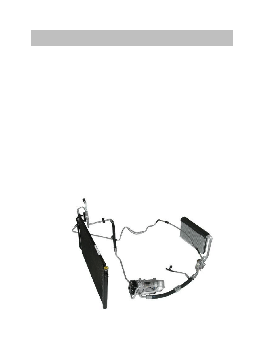
The system is comprised the following basic components:
• Compressor
• Condenser
• Condenser fan
• Receiver Dryer/collector
• Expansion valve
• Evaporator
• Hoses and pipes
• Regulation and control devices
E90 A/C System Components

4
A/C System and Components
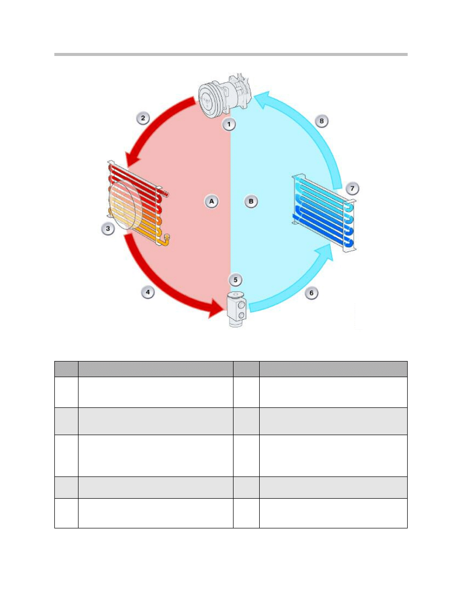
The Refrigerant Cycle
The refrigerant circuit is divided into a high pressure section (high side) and a low pres-
sure section (low side). The high pressure side is comprised of the compressor, con-
denser, condenser fan, pressure sensor, receiver dryer and expansion valve. The low pres-
sure side also involves the compressor and expansion valve along with the evaporator and
blower fan.The expansion valve separates the high-pressure side of the system from the
low-pressure side. Pressurized liquid refrigerant exits the receiver dryer and as it passes
through the metered orifice of the expansion valve it decompresses and boils.
This change of state causes the refrigerant to absorb heat as it makes its way through the
inside of the evaporator. The amount of refrigerant released is controlled by the expansion
valve based on evaporator temperature and pressure as well as the temperature of the air
passing through the evaporator and proportional to the cooling demand. If too little refrig-
erant enters the evaporator, poor cooling results. If too much refrigerant enters, it might
not completely boil away and liquid refrigerant might return to the compressor, causing
damage to the system.
The pressure and temperature are measured by passing the refrigerant through the
expansion valve at the outlet of the evaporator. The top section of the valve measures the
temperature of the refrigerant intake and the refrigerant pressure acts on the
underside of the diaphragm.
The valve controls flow of refrigerant through the evaporator as pressure and temperature
of the gaseous refrigerant at the evaporator outlet are used to open and close the valve
via a diaphragm.
The flow rate is increased and decreased as air temperature at the evaporator output
rises and falls. This control procedure runs continuously for as long as the air conditioning
system is in operation.
Heat is extracted from the interior as it is circulated by a blower fan through the evaporator
outer surface area. This transfers heat from the cabin air to the vaporizing refrigerant with-
in, reiterating that an air conditioning system operates by removing heat instead of adding
cold.
An engine driven compressor extracts the gaseous low pressure refrigerant from the
evaporator, compresses it and heats it. The now compressed and superheater gas is
pumped through the condenser where it cools to a high pressure liquid as outside air is
forced through the condenser fins while driving or via the condenser cooling fan.
The refrigerant now in a sub-cooled liquid state flows from the condenser to a liquid
reservoir (receiver dryer) where it is collected. Any moisture and impurities are removed
by the desiccant in the receiver dryer. This high pressure liquid now flows back into the
low pressure side of the system, where it is forced through the expansion valve metered
orifice back into the evaporator on its way to complete the cycle once again.
5
A/C System and Components
Index
Explanation
Index
Explanation
1
The compressor increases the pressure and
the temperature of the gaseous refrigerant.
6
Refrigerant in vapor state at
low temperature/low pressure.
2
Gaseous refrigerant at
high temperature/high pressure.
7
The evaporator dehumidifies the air flow as the
cold refrigerant absorbs heat.
3
The condenser functions as a heat exchanger. The
air flowing past absorbs heat as the hot refrigerant
gas cools down it condenses into a liquid.
8
Gaseous refrigerant at
low temperature/ low pressure.
4
Liquid refrigerant at medium
temperature/high pressure.
A
High-pressure side
5
The expansion valve relieves the pressure of the
refrigerant which induces a large drop in
temperature.
B
Low-pressure side
Refrigerant Cycle
6
A/C System and Components
Air Conditioning System Components
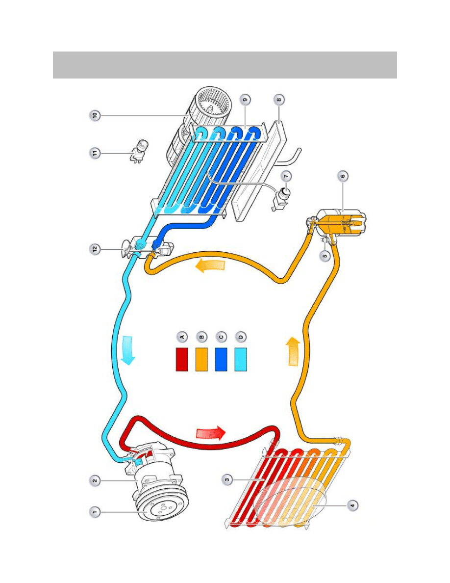
Typical A/C System Components
7
A/C System and Components
Compressors
Compressors used in air conditioning systems operate based on various principles:
• Reciprocating piston compressor
• Spiral compressor
• Vane-type compressor
• Swash plate compressor
The following description deals with the swash plate compressor (also known as wobbler
compressor) as it is the most commonly used in present BMW vehicles.
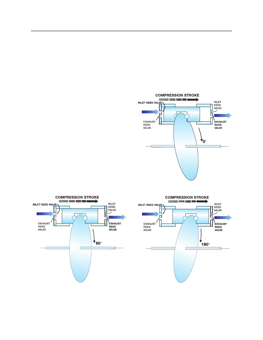
The swash plate converts the rotary motion of the drive shaft into an axial motion that
along with a changing pivot point varies the stroke of the pistons.
The varying piston stroke delivers a variable cylinder displacement, directly affecting and
reacting to the A/C system pressure.
Depending on the design, this may involve 5 to 7 pistons that are arranged in a circle
around the drive shaft. An intake/pressure valve is assigned to each piston, these valves
open/close automatically in time with the operating cycle.
Index
7Explanation
Index
Explanation
1
Electric clutch
9
Evaporator
2
Compressor
10
Evaporator blower
3
Condenser
11
Blower Switch
4
Auxiliary fan
12
Expansion Valve
5
Pressure sensor
A
High pressure, gas
6
Liquid Receiver Dryer
B
High pressure , liquid
7
Evaporator temperature sensor
C
Low pressure , liquid
8
Condensation water tray
D
Low pressure, gas
8
A/C System and Components
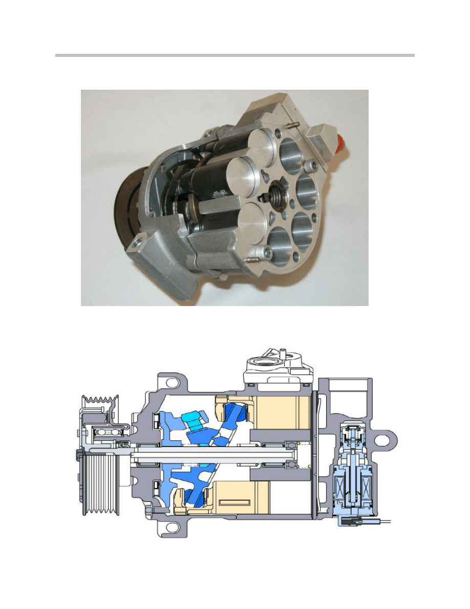
Seven Piston Swash Compressor Cut-away
Seven Piston Swash Compressor
9
A/C System and Components
The design layout of the air conditioning system is set to full load. The output of the com-
pressors, however, depends on the engine speed. Consequently, speed differences of up
to 2000 rpm can occur. These fluctuations have an influence on the charge of the evapo-
rator and therefore on the cooling capacity of the air conditioning system.
Output-controlled compressors with variable displacement were developed for the pur-
pose of adapting to different engine speeds, ambient temperatures of interior tempera-
tures selected by the driver. This adaptation is achieved by varying the angle of the swash
plate.
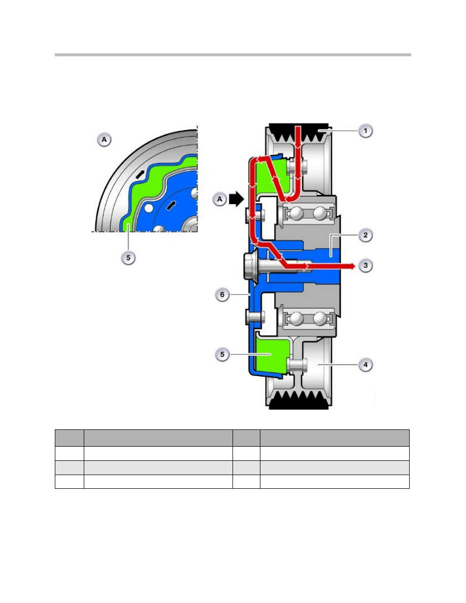
The swash plate is guided in longitudinal
direction in a slide rail or runner.
The stroke of the pistons and thus the delivery
capacity are determined by varying the inclina-
tion of the swash plate.
The inclination is dependent on the chamber
pressure and therefore on the pressure ratios
at the top and bottom of the pistons.
The inclination is supported by springs
arranged before and after the swash plate.
High Displacement
Medium Displacement
Low Displacement
10
A/C System and Components
Features
• Current vehicles use a 7 piston-swash plate compressor design.
• Variable displacement volume for adaptation of the required refrigerating capacity.
• Pulley drive with or without magnetic clutch.
• Control valve for controlling the pressure ratio in the compressor.
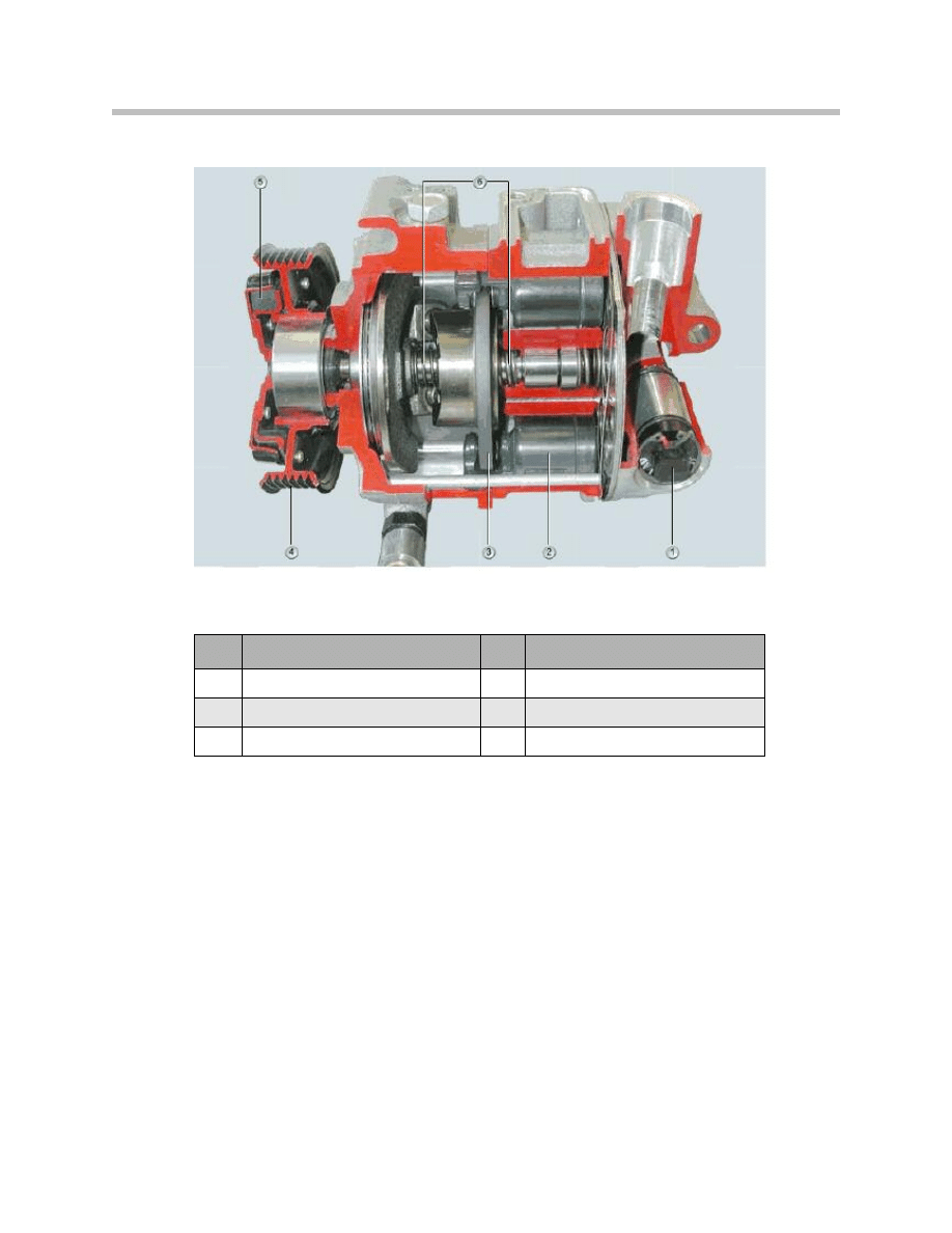
Clutchless Compressor Cutaway
Index
Explanation
Inde
x
Explanation
1
Control Valve Solenoid
4
Pulley with bearing
2
Piston
5
Formed rubber element
3
Swash Plate
6
Control Springs
11
A/C System and Components
Compressor Control Valve
Depending on application, the compressor may or may not use a magnetic clutch. In
vehicles that use clutchless compressors they are constantly engaged when the engine
is running. This results in constant drag on the engine which affects emissions and fuel
economy.
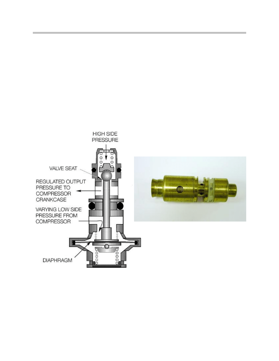
The compressor output is always variable displacement and is controlled internally by
either a mechanical control valve that operates solely on A/C pressure differential and
does not need electronic signals or an electronic control valve that operated directly by
signals from the IHKA control module depending on the system demand.
Mechanical Control Valve
12
A/C System and Components
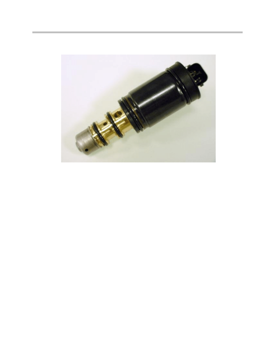
Electronic Control Valve
Function
The control valve in the compressor is controlled infinitely variable by the IHKA control
unit. Depending on the ventilation temperature, outside temperature, interior temperature
as well as the target and actual evaporator temperature, the pressure in the crankcase of
the compressor is varied by means of a pulse-width-modulated voltage signal.
The compressor is driven by constant engagement pulley (Clutchless) and a ribbed V-
belt.The inclination of the swash plate changes, determining the displacement volume
and therefore the refrigerating capacity. The compressor output capacity and therefore
the delivery volume can be set from 0-2% minimum to 100% maximum.
For example, the control unit (IHKA) activates the control valve accordingly when a higher
refrigerating capacity is required. A pulse width-modulated voltage signal moves a tappet
(plunger) in the control valve. The time the voltage is applied determines the adjustment
range. The adjustment varies the opening cross section in the control valve between the
high pressure and the pressure in the crankcase.
Electronic Control Valve
E70 Compressor Control
The IHKA is the master for controlling the A/C compressor. Pressing the A/C button on
the air conditioning system operating unit switches the air conditioning system to the
ready state.The IHKA transmits a speed increase request to the DME (ECM).
Depending on the temperature and the nominal-value setting, the IHKA sends a cooling
power request to the DME (ECM) If the DME (ECM) is ready and in a position to provide
torque of > 20 Nm, the DME (ECM) issues a release for a load connection of up to
30Nm. This release is also monitored by the junction box. The IHKA issues a command
to the junction box to couple the connection. The junction box returns the coupling status
to the DME (ECM).
The compressor output is controlled by the IHKA control unit by means of an infinitely
variable control valve. The IHKA control command is converted into infinitely variable pro-
portional powering of the control valve in the junction box.
The evaporator temperature is controlled to a value of between 2°C and 8°C depending
on the cooling power request. The temperature sensor signal in the evaporator is used as
a feedback signal to the IHKA control unit. The refrigerant request is limited by the poten-
tial evaporating power of the evaporator. The evaporator is prevented from icing up by
controlling the compressor output (appropriate reduction).
In order to reduce CO
2
emission, avoid unstable conditions when the engine is idling and
for full load acceleration, the DME can activate a compressor shut-off via the junction box.
If appropriate parameters are present, the solenoid coupling of the compressor is opened.
Note: E70 vehicles with the N52 engine are fitted with A/C compressors with
magnetic clutches. Vehicles with the N62 engine will initially be equipped
with clutchless A/C compressors but will change to clutches later in pro-
duction. This is implemented as a CO
2
emission reduction measure.
13
A/C System and Components
K-CAN signals for controlling the A/C compressor at the IHKA control unit
IN/OUT
Signal
Source/sink
OUT
Cooling power request /Torque request
DME Junction box
IN
Release and provision of torque
DME Junction box
OUT
Close coupling
Junction box
OUT
Power control valve
Junction box
IN
Compressor coupling status signal
Junction box
14
A/C System and Components
Compressor Drive Pullies
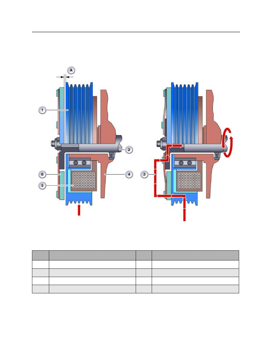
Magnetic Clutch
The magnetic clutch provides the drive connection between the compressor
and the engine while the engine is running.
The clutch design consists of:
• Pulley with bearing
• Spring plate with hub
• Solenoid coil
The hub of the spring plate is securely mounted on the compressor drive shaft.
The pulley is mounted on the outer race of the compressor drive shaft bearing.
The solenoid coil is connected to the compressor housing. There is a clearance "A"
between the spring plate and pulley.
Function
The compressor is driven with the use of a ribbed V-belt riding on the pulley, turned by
the engine (arrow). A voltage is applied to the solenoid coil when the A/C is requested.
The resulting force from the magnetic field pulls the spring plate against the spinning pul-
ley (bridging the clearance "A"), thus establishing a positive connection between the pul-
ley and drive shaft of the compressor.
The compressor is now running. It continues to operate until the power circuit to the
solenoid coil is interrupted. Springs then release the spring plate from the pulley.
The pulley runs freely without engaging the compressor shaft.
15
A/C System and Components
Magnetic Clutch
Index
Explanation
Index
Explanation
1
Pulley with bearing
5
Solenoid coil
2
Compressor drive shaft
6
Spring plate with hub
3
Power flow
A
Clearance between spring plate and pulley
4
Compressor housing
16
A/C System and Components
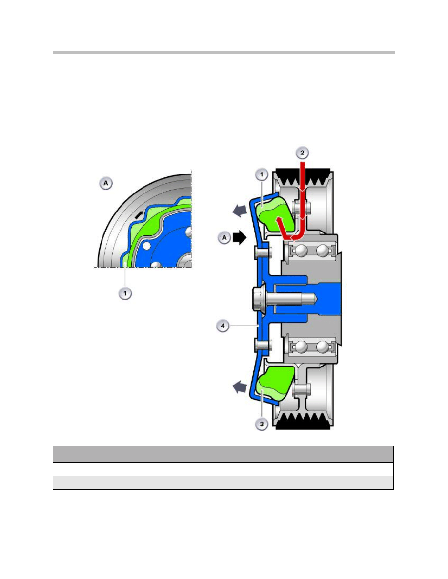
Clutch-Less Pulley
Used as overload protection for compressor in operation; the ribbed V-pulley and the
drive plate are positively connected by a rubber formed element. When the compressor
is operative, both discs turn together at the same ratio.
Compressor in Operation
Index
Explanation
Index
Explanation
1
Ribbed V-belt
4
Pulley
2
Compressor shaft
5
Formed rubber element
3
Power flow of a good compressor
6
Drive plate
17
A/C System and Components
Function
In the event the compressor ceases and the drive plate stops turning, thus increasing the
acting forces between the pulley and the drive plate; the pulley presses on the formed
rubber element in the direction of rotation against the locked compressor drive plate. The
formed sections of the rubber element are sheared off thus disengaging the connection
between the pulley and the drive plate. The pulley now continues to rotate freely. This
prevents damage to the ribbed V-belt and therefore to the engine.
Compressor Failure
Index
Explanation
Index
Explanation
1
Sheared material
3
Deformation of formed rubber element
2
Power flow after formed rubber element shears
4
Drive plate locked

18
A/C System and Components
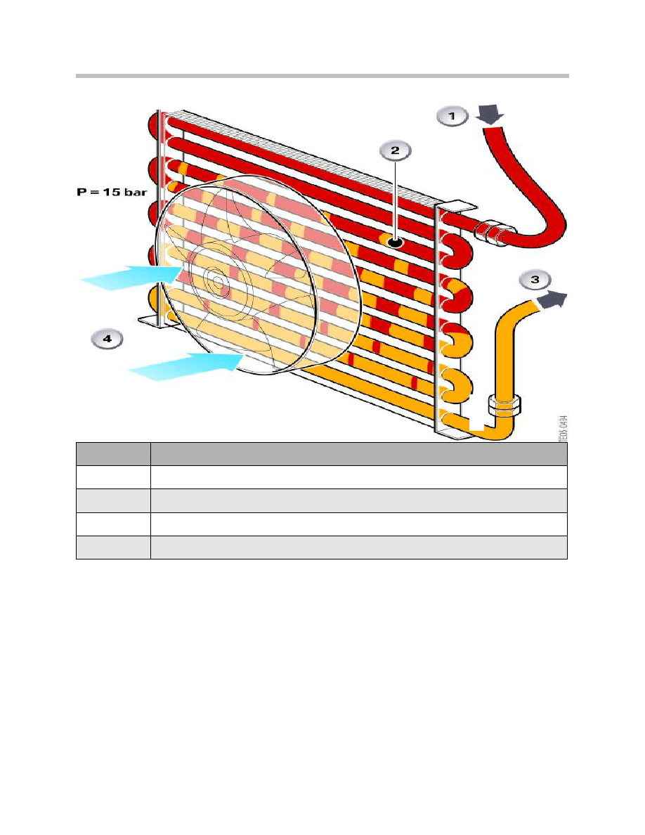
Condenser
The condenser is made up of tube coils and fins that are firmly secured to the tubes so
as to achieve a large heat exchange area and effective heat transmission.
The task of the condenser is to give off the energy, which the refrigerant has taken up
during compression in the compressor, in the form of heat to the outside air via the fins.
As a result, the gaseous refrigerant becomes liquid again.
The removal of energy is necessary so that when the refrigerant is injected into the evap-
orator it can absorb heat energy again from the air to be cooled.
The condenser utilizes the energy difference between the hot refrigerant under pressure
and the cooler outside air for the purpose of performing its task.
Function
The procedures in the condenser are divided into three operations.
In the first stage, the hot gaseous refrigerant, at a temperature of approx. 60-120°C com-
ing from the compressor at a pressure of 10 to 25 bar, gives off its superheat to the out-
side air.
The actual condensation takes place in the second phase where the refrigerant has lost
so much energy that it becomes liquid.
In the third phase, further energy is taken from the now liquid refrigerant. This state is
referred to as refrigerant sub-cooling. This phase also makes sure that no gas bubbles
can form on the refrigerant’s way to the expansion valve. The sub-cooling takes more
heat away from the refrigerant than is necessary for actual condensation.
The sub-cooled refrigerant in the evaporator can absorb a larger quantity of heat and thus
increase the refrigerating capacity of the system.
The auxiliary fan arranged directly before the condenser ensures an effective supply of
cooling air. The refrigerant remains in the condenser at a high pressure of approx. 10-25
bar. Approx. 80-90% of the condenser power is used in the actual condensation process
where a temperature drop of 30 to 40°C occur.
Note: The greater the sub-cooling of the refrigerant in the condenser the
greater the refrigerating capacity of the air conditioning system.
19
A/C System and Components
Service Information
• The distance between the condenser and vehicle radiator must be as large
as possible.
• The condenser fins must not be bent or dirty.
• Ensure the auxiliary fan is operating correctly.
• A soiled condenser results in poor condensation and unnecessarily high
operating pressures.
Condenser
Index
Explanation
1
Refrigerant inlet temperature = +80°C
2
Dew point + 55°C
3
Refrigerant outlet Temperature approx.+45°C
4
Outside air +30°C
20
A/C System and Components
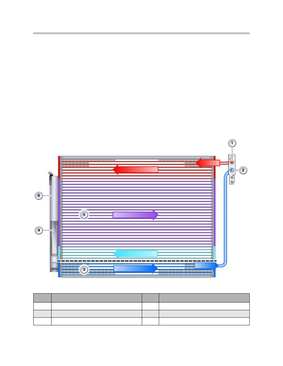
Condenser Module
In the past, the high pressure section of the refrigerant circuit was made up of a series of
individual components such as the condenser with mounting bracket and connections,
separately mounted liquid reservoir with filter and dryer, pressure sensor etc.
As the result of the system integration to form the condenser module with flat tubular
condenser, the liquid reservoir (dryer) was mounted on the side of the condenser.
The condenser is divided in two cooling sections. Inside the top 2/3 of the condenser the
hot, compressed gaseous refrigerant changes into a liquid as it cools. It enters the receiv-
er dryer through inlet holes located at the lower 1/3 of the condenser cooling area. After
passing through the desiccant in the dryer the liquid refrigerant now enters the con-
denser again and circulates through the lower 1/3 section on its way to the expansion
valve. It is now considered a SUB-COOLED liquid.
Index
Explanation
Index
Explanation
1
Hot gas from the compressor
4
Filter dryer
2
Undercooled liquid refrigerant
5
Condenser section
3
SUB-COOLED section
6
Collection reservoir
21
A/C System and Components
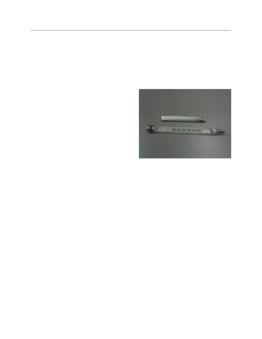
The condenser module introduced in the E53 features an integrated filter element with
woven plastic fabric. A further advantage is the increase in condenser capacity by more
effective sub-cooling of the refrigerant. Consequently, the refrigerating capacity remains
constant even as the charge volume decreases to 50% of the normal quantity.
The filter/dryer cartridge can be changed by undoing a screw plug. The refrigerant is
dried by a bag containing a molecular filter desiccant made from silica gel.
Note: The condenser module with
replaceable cartridge dryer ele-
ment is installed in E53, E6X,
E70,and E9X models..
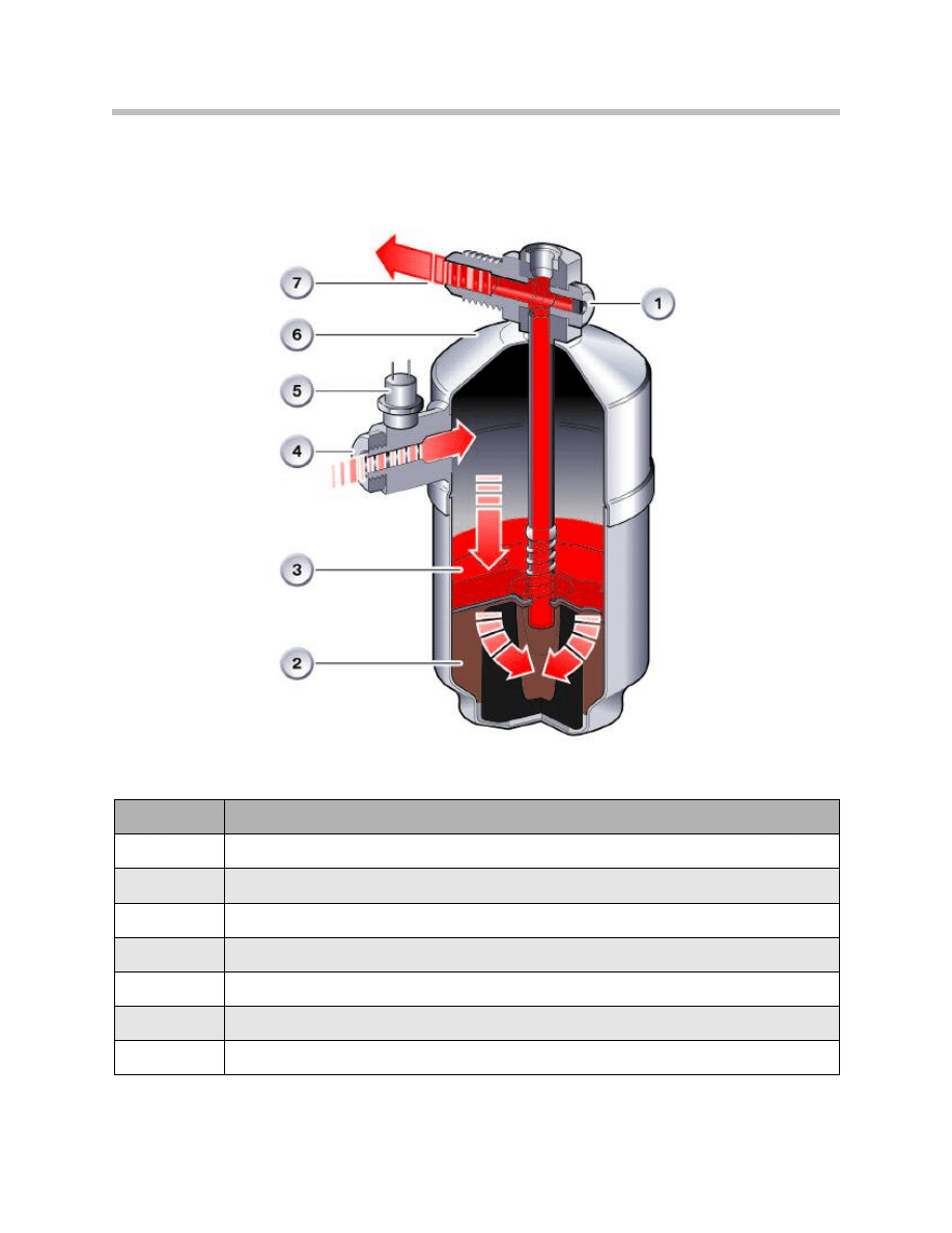
Receiver Dryer
The liquid reservoir serves as an expansion and supply reservoir for the refrigerant. Due to
varying operating conditions such as thermal load at the evaporator and condenser as
well as the compressor speed, varying quantities of the refrigerant are pumped through
the circuit. A liquid reservoir is installed for the purpose of balancing out these fluctuations
as it absorbs moisture.
The liquid refrigerant coming from the condenser is collected in the reservoir and only the
quantity that is required in the evaporator for cooling the air flows further. The drying
agent can chemically bind a small quantity of water thus removing it from the circuit.
Depending on the version, the desiccant can absorb 6-12g (0 .2-0.4oz) of water. The
absorption rate is dependent on the temperature. The absorption rate increases as the
temperature decreases. For example, if a dryer is saturated at a temperature of 40°C
(104°F), it will expel water again at 60°C (140°F). Debris from the compressor, dirt and
similar mater are also filtered out.
Note: On systems that use conventional dryers, these dryer are non
serviceable and must be replaced (E83, E85, E86)
22
A/C System and Components
Index
Explanation
1
Pressure relief valve ( older System)
2
Filter Dryer
3
Screen Filter
4
Connection from condenser
5
Pressure sensor
6
Housing
7
Outlet to expansion valve
Conventional Type Dryer

23
A/C System and Components
Function
The refrigerant enters the liquid reservoir from above and flows downward along the
inside of the housing. It must then pass through the filter dryer where moisture is extract-
ed. The refrigerant rises through a plastic screen filter in the dryer and impurities are fil-
tered out.
The filter element can be compared to a sponge which can absorb and bind water.
Molecular filters and silica gel bind moisture and in addition moisture activated aluminum
oxide is used to bind acid.
The dryer is integrated in the condenser in the new air conditioning systems as installed
in the E53, E6X, E70, and E9X models.
It is therefore no longer a separate component (see condenser module).
Service Information
The following points must be observed when working on the liquid reservoir (dryer):
• The dryer bottle or the dryer insert in an operative air conditioning system with no
leaks need not be replaced at regular inspection intervals.
• However, the dryer bottle or the dryer element must be replaced in the case of:
- Contamination of the refrigerant circuit through metal chips (compressor ).
- Leaks in the air conditioning system or loss of refrigerant.
- The refrigerant circuit being opened for longer than 24 hours, during a repair
procedure.
- Prior to installation, keep the dryer (or dryer element) closed for as long as
possible to ensure no moisture is absorbed from the ambient air.
24
A/C System and Components
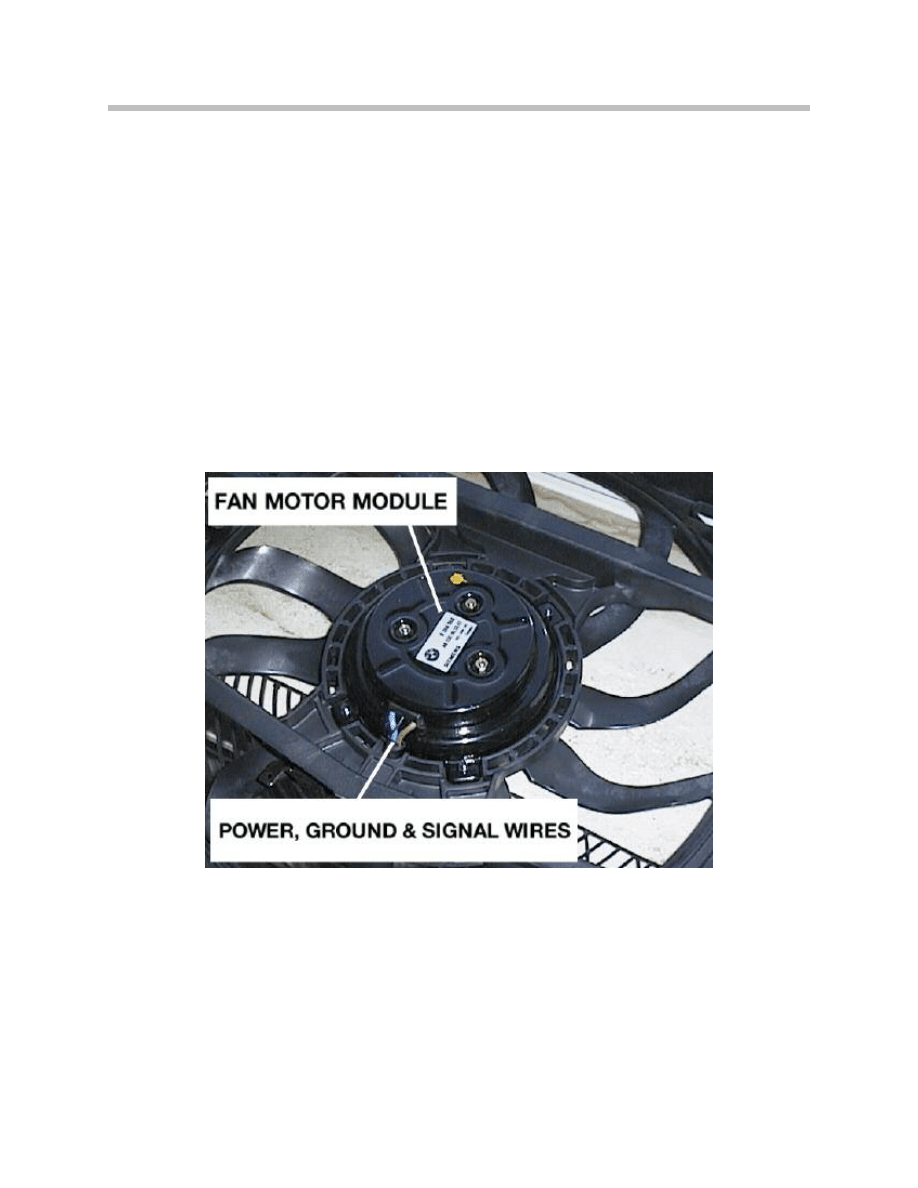
Condenser Fan (Auxiliary Fan)
The auxiliary fan is used to cool the outer surface of the condenser and consequently the
hot gaseous refrigerant that flows through it. As the refrigerant cools, it condenses back
into liquid state.
The engine management computer communicates with the fan control module which
governs the auxiliary fan operation.
The fan is activated based on the following conditions:
• The radiator outlet temperature exceeds a preset temperature.
• The refrigerant pressures reach a predetermined crucial point.
• Vehicle Speed
• Battery Voltage Level
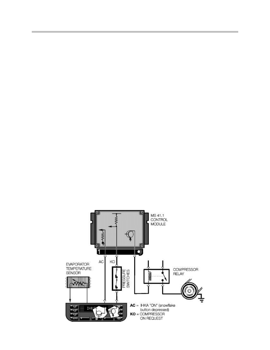
Auxiliary Fan Circuit (Early Models)
The condenser on BMW A/C systems is equipped with an auxiliary fan the provides addi-
tional air flow through the radiator and condenser, when needed.
Auxiliary fan control systems vary between vehicles. The following is a typical example of
how the auxiliary fan is controlled.
The auxiliary fan is controlled by two normally open relays, a normal speed relay, which
runs the fan at the “normal” (low) speed; and a high speed relay which runs the fan at the
high speed.
25
A/C System and Components
The A/C control module grounds the normal speed relay whenever the A/C system is
turned on. This causes the fan to run at normal speed.
The relays are also energized by a (normally open) double temperature switch, which
senses coolant temperature in the radiator. When coolant temperature rises above 180°F
(82°C), the normal speed half of the switch closes, powering the normal speed relay, and
the auxiliary fan runs at normal speed, whether or not the snowflake button is pressed.
When the temperature rises above 190°F (88°C), the high speed half of the switch clos-
es, powering the high speed relay, and the auxiliary fan runs at high speed.
There is also an intermediate pressure switch fitted in the receiver/dryer. This switch
which is normally open, closes when the refrigerant pressure exceeds 260 psi. This ener-
gizes the high speed relay and runs the auxiliary fan at high speed.
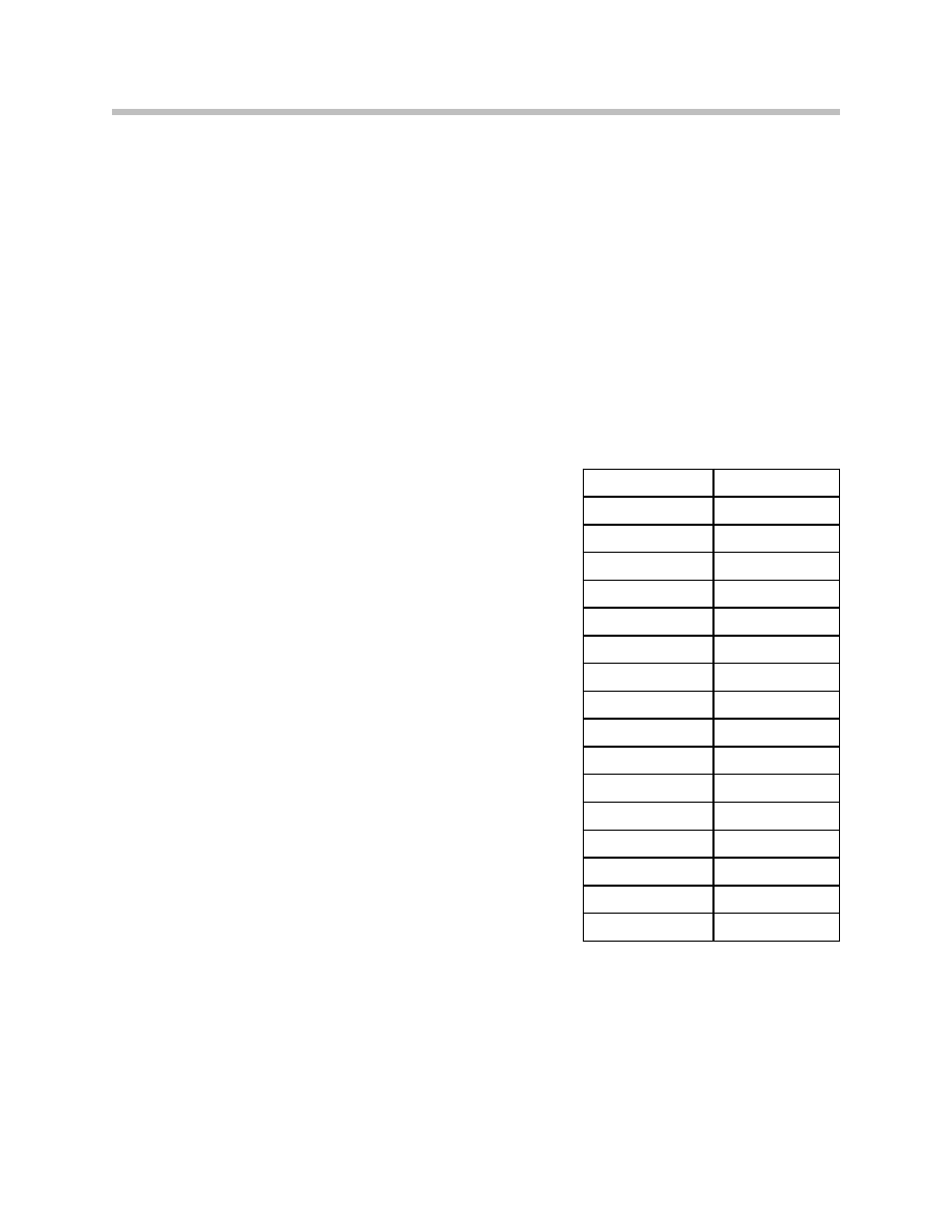
Refrigerant Pressure-fan Stage Conversion Table
The pressure sensor receives a 5 volt power supply
from the IHKA control unit. The sensor signal is evaluat-
ed and forwarded to the DME via the K-Bus. In the
process, the refrigerant pressure in the air-conditioning
circuit is converted to a load torque and calculation for
the required fan speed (stage).
Each fan stage that is determined is transmitted from
the ECM to the auxiliary fan output stage. Prerequisite
is a speed less than 50 mph.
Note: BMW auxiliary fan operation and strategy
varies within vehicles. Refer to the
Electrical Troubleshooting Manuals (ETM)
for vehicle specific information.
Pressure in bar
Fan stage
8
0
9
1
11
2
13
3
14
4
15
5
16
6
17
7
18
8
19
9
20
10
21
11
22
12
23
13
24
14
>24
15

26
A/C System and Components
Thermostatic Expansion Valve (TEV)
The thermostatic expansion valve (TEV) regulates the flow of refrigerant through the
evaporator depending on the degree of so called "overheating" of the refrigerant vapor at
the evaporator outlet. The amount of refrigerant that can evaporate under the respective
operating conditions is fed to the evaporator via the TEV. As one of the separating points
between the high-pressure and low-pressure sections, the TEV is installed in the refriger-
ant circuit ahead of the evaporator.
The flow of refrigerant through the expansion valve is controlled depending on tempera-
ture and pressure in order to achieve optimum refrigerating capacity in the evaporator.
This metering system ensures the entire heat exchange area is utilized efficiently as pres-
surized liquid refrigerant expands in the evaporator and absorbs heat from the passenger
compartment.
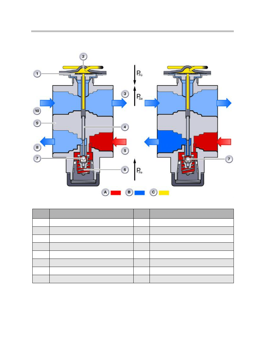
Function
The pressure and temperature are measured by passing the refrigerant through the
expansion valve at the outlet of the evaporator. The top section of the TEV measures the
temperature of the refrigerant intake and the refrigerant pressure acts on the underside of
the diaphragm.
The valve needle is pressed down against a spring to open the valve, allowing liquid
refrigerant to flow into the evaporator. The refrigerant evaporates, pressure and tempera-
ture drop. The pressure and temperature of the gaseous refrigerant at the evaporator out-
let are used to open and close the valve via a diaphragm.
When the air temperature at the evaporator outlet drops, the sensing gas in the
diaphragm chamber contracts, this moves the valve needle upward and reduces the
coolant flow rate to the evaporator.
The flow rate is increased again when the air temperature at the evaporator output rises.
Increasing pressure at the evaporator outlet assists the valve closing action. Decreasing
pressure assists the valve opening action. This control procedure runs continuously for as
long as the air conditioning system is in operation.
The following points must be observed when working on the expansion valve:
• Very little refrigerant flow through the evaporator will result in poor A/C output.
• If too much refrigerant flows into the evaporator, it will flood and cause possible
compressor damage.
• The setting of the expansion valve must not be adjusted or varied
(except for instructions in the Service Information).
• The expansion valve must not be repaired.
• Seals must be replaced every time the pipes and hoses are released.
27
A/C System and Components
Expansion Valve
Index
Explanation
Index
Explanation
1
Diaphragm
9
Housing
2
Sending gas
10
From evaporator
3
To compressor
A
High pressure
4
Valve needle
B
Low pressure
5
From condenser
C
Sensing gas pressure
6
Spring
Pfu
Pressure in sensor line (sensor fill)
7
Ball
Psa
Evaporator pressure (low pressure)
8
To evaporator
Pfe
Control spring force
28
A/C System and Components
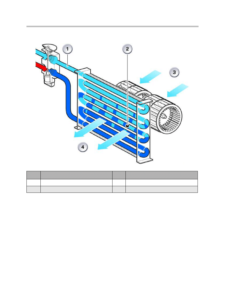
Evaporator
The evaporator is installed in the housing of the integrated automatic heating and air con-
ditioning system (IHKA) or the integrated heating and air conditioning control (IHKR). It
consists of a coiled tube with press-fitted fins. The refrigerant flows through the coiled
tube. The blower blows the air to be cooled through the fins. To improve heat transmis-
sion, the fins are designed so that they cover a large surface area.
In order to uniformly supply the entire area of the evaporator with liquid refrigerant, the
refrigerant is divided into several subsections of equal size after being injected into the
evaporator.
This design layout greatly increases the efficiency of the evaporator. The divided refriger-
ant channels are reunited at the end of the coiled tube where they are drawn in by the
compressor.
Index
Explanation
Index
Explanation
1
Low pressure Pa 2 bar
3
Air inlet + 30°C
2
Boiling point then -10°C
4
Air outlet +12°C

29
A/C System and Components
Like the condenser, the evaporator is also a heat exchanger. It is responsible for the main
task of the air conditioning system, extracting heat from the passenger compartment.
A further task of the evaporator is to dry the air by removing moisture. The condensed
moisture is expelled to the outside of the vehicle. Air dried in this way assists in keeping
the windscreen and windows free of condensation.
Function
The evaporator functions as a heat exchanger in that thermal energy is taken externally
from the air and given off internally to the refrigerant. The most important factor is the
energy absorption by the refrigerant during the transition from the liquid to the gaseous
state. This transition requires a great deal of energy in the form of heat which is taken
from the air blown through the system of fins. The refrigerant is evaporated at low pres-
sure and by the heat delivered from the passenger compartment by the use of a blower
fan. The refrigerant cools down greatly while the injection procedure ensures the pres-
sure drops from 10-20 bar to approx. 2 bar.
Service Information
The following points must be observed when working on the evaporator:
• The evaporator fins must not be dirty or bent. This would result in the growth of bac-
teria and odor.
• The evaporator fins must not ice up. If the evaporator does ice up, the fault will be in
the area of the evaporator temperature sensor. This situation would result in com-
pressor damage following a longer period of operation of the air conditioning system.
• The micro filter change intervals must be maintained to insure adequate air flow.
• The condensation water drain must not be clogged and water must drain off freely.
• The evaporator temperature sensor must be installed correctly.
Note: To treat bacteria and odor complaints, a special cleaning and treatment
procedures must be followed. SI 64 04 03 “A/C System Musty Odor” can
be found in TIS.
30
A/C System and Components
Hoses and Pipes
The system of hoses and pipes serves the purpose of establishing the connection
between the individual components of the air conditioning system. The connections are
sealed with O-rings.
The hoses and pipes consist of various materials, different shapes and sizes. A fold,
flange or threaded connection is provided at the end of each line.
To date, vehicle air conditioning systems were equipped with flexible hose lines. More
recently, aluminum pipes and combinations of aluminum pipes and hose lines have also
been used for space-saving purposes.
The hose material is an elastomer formed from various rubber layers. The inside is com-
patible with the refrigerant and the refrigerator oil.
The outside is compatible with weather influences, oils, fuels and other substances used
in the vehicle.
In addition, these rubber layers must also be impermeable to the refrigerant and the
refrigerator oil of the compressor (from the inside) and to moisture (from the outside).
The refrigerant R134a has smaller molecules than R12 and could therefore more easily
penetrate the rubber layers of the hoses.
Thanks to the use of an additional nylon sheathing and a maximum of two inner rein-
forcements made from woven textile, hose lines are now available that are suitable for use
in R134a air conditioning systems.
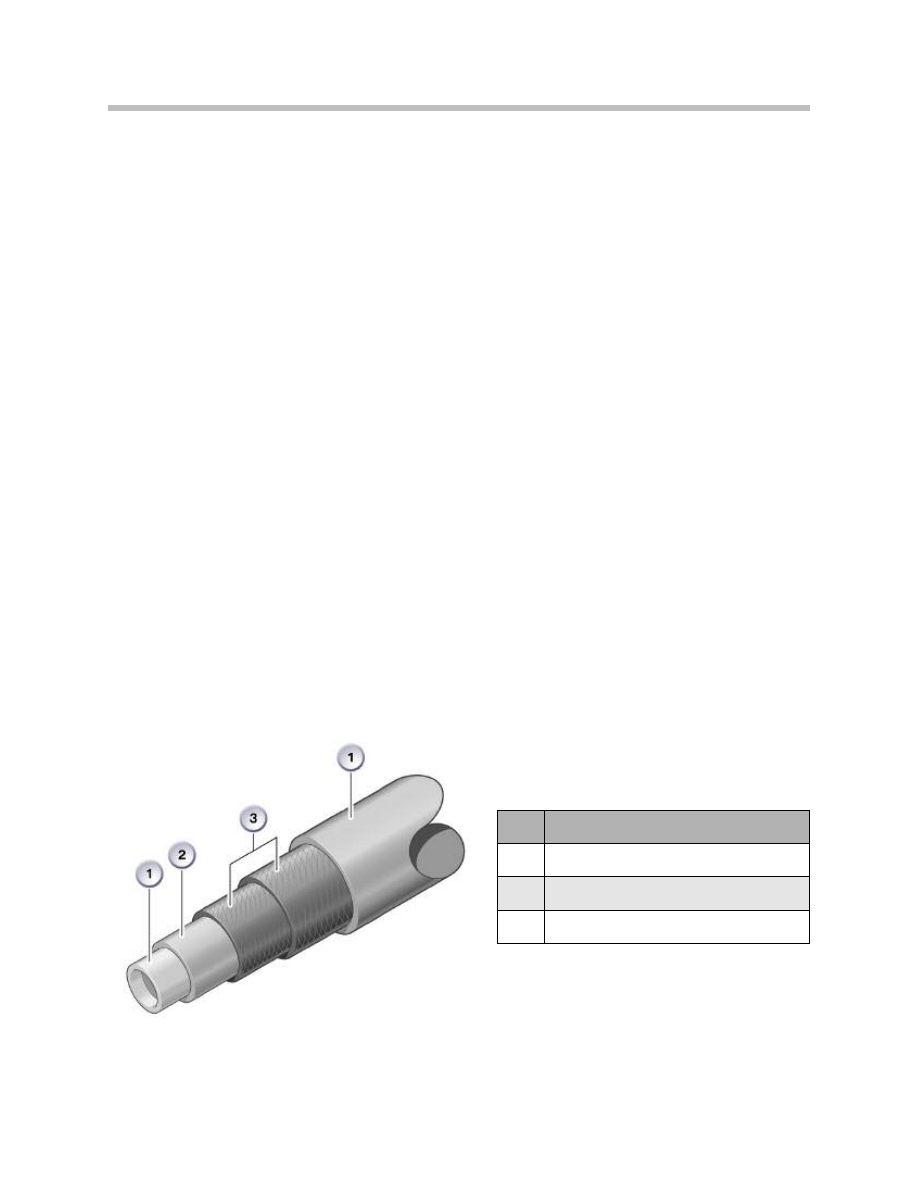
Hose Material Composition
Index
Explanation
1
Elastomer
2
Nylon sheathing from woven textile
3
Double reinforcement
Document Outline
- Main Menu
- Principles of Heating and Refrigeration
- Refrigerant
- Engine Cooling/Heating System
- A/C System and Components
- Climate Control Components
- Climate Control Systems and Functions
- Air Conditioning Service and Diagnosis
- Future Technology
- Glossary
Wyszukiwarka
Podobne podstrony:
Electronics 4 Systems and procedures S
Basic AC Generators and Motors
04 Wyklad SystemPlikowv2
04 AC 14 Calculation Guide
04 Lubrication System
712[06] S1 04 Montowanie systemów sufitów podwieszanych
Ship Power Systems and Design Part 3
[0] Step Motor And Servo Motor Systems And Controls
system bankowy 25.04, Uczelnia, Systemy bankowe
EL 04 2003 Systemy Wbudowane 1
[Mises org]Hayek,Friedrich A A Free Market Monetary System And Pretense of Knowledge(1)
8 Marketing information systems and forecasting
Electronics 4 Systems and procedures S
Basic AC Generators and Motors
NIST Information Security Continuous Monitoring for Federal Information Systems and Organizations
93ZJ Secc 11 Exhaust System and Intake Manifold
Matlab Tutorial for Systems and Control Theory (MIT) (1999) WW
07 AC Service and Diagnosis
96ZJ 11 EXHAUST SYSTEM AND INTAKE MANIFOLD
więcej podobnych podstron