
Initial Print Date: 01/09
Table of Contents
Subject
Page
Head-up Display System Schematic Circuit Diagram. . . . . . . . . . . . . . . .6
Switch-on Conditions . . . . . . . . . . . . . . . . . . . . . . . . . . . . . . . . . . . . . .10
Switch-on Performance . . . . . . . . . . . . . . . . . . . . . . . . . . . . . . . . . . . . .10
Operating-hours Counter . . . . . . . . . . . . . . . . . . . . . . . . . . . . . . . . . . . .12
Display Area of Head-up Display . . . . . . . . . . . . . . . . . . . . . . . . . . . . .12
Incorrect Windshield Fitted . . . . . . . . . . . . . . . . . . . . . . . . . . . . . . . . . .19
Check Control Messages . . . . . . . . . . . . . . . . . . . . . . . . . . . . . . . . . . . . . .21
Driver Assistance System Control Panel . . . . . . . . . . . . . . . . . . . . . . .22
Instrument-lighting Dimming . . . . . . . . . . . . . . . . . . . . . . . . . . . . . . . . .22
Adjusting the Height of the Horizon on the HUD . . . . . . . . . . . . . . . . . .24
Vertical Rotation of the HUD . . . . . . . . . . . . . . . . . . . . . . . . . . . . . . . . . . .24
F01 Head-up Display
Revision Date:

Subject
Page
Calling/quitting Test Functions . . . . . . . . . . . . . . . . . . . . . . . . . . . . . . .25
Correcting Distortion (Warping) . . . . . . . . . . . . . . . . . . . . . . . . . . . . . .26

Subject
Page
BLANK
PAGE

4
F01 Head-up Display
Head-up Display (HUD)
Model: F01/F02
Production: From Start of Production
After completion of this module you will be able to:
• Describe the Head-up Display of the F01/F02
• Describe the functions of Head-up Display of the F01/F02
• Identify the components of the Head-up Display of the F01/F02
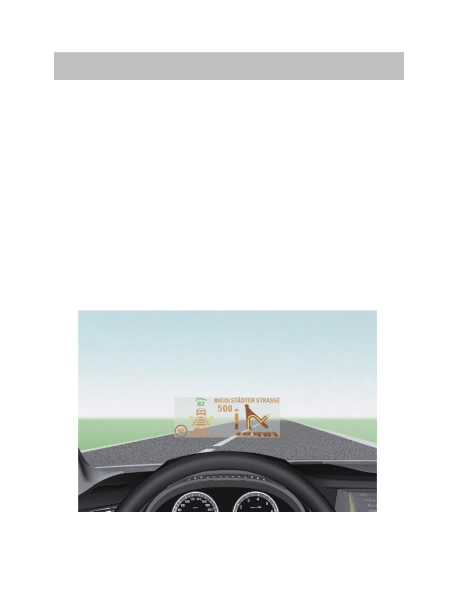
The very name “Head-Up” describes the principle benefit of this system. The Head-up
Display (HUD) projects a virtual image into the driver’s field of vision. Important informa-
tion such as cruise control details or graphical directions from the navigation system are
projected onto the windshield and are thus permanently visible within the driver’s field of
view.
The driver of a BMW thus has the important data and graphics put up in his field of view,
just like a pilot in his jet fighter.
The head-up display in the new BMW 7 Series incorporates various functions aimed at
enhancing road safety and driver convenience.
That includes display of:
• Information from the DCC cruise control system
• Information from the navigation system
• Check Control messages
• Road speed
Having the displays in the driver’s direct field of view increases safety, as the eyes are
always on the traffic.
5
F01 Head-up Display
Introduction
Head-up Display (HUD) in F01/F02
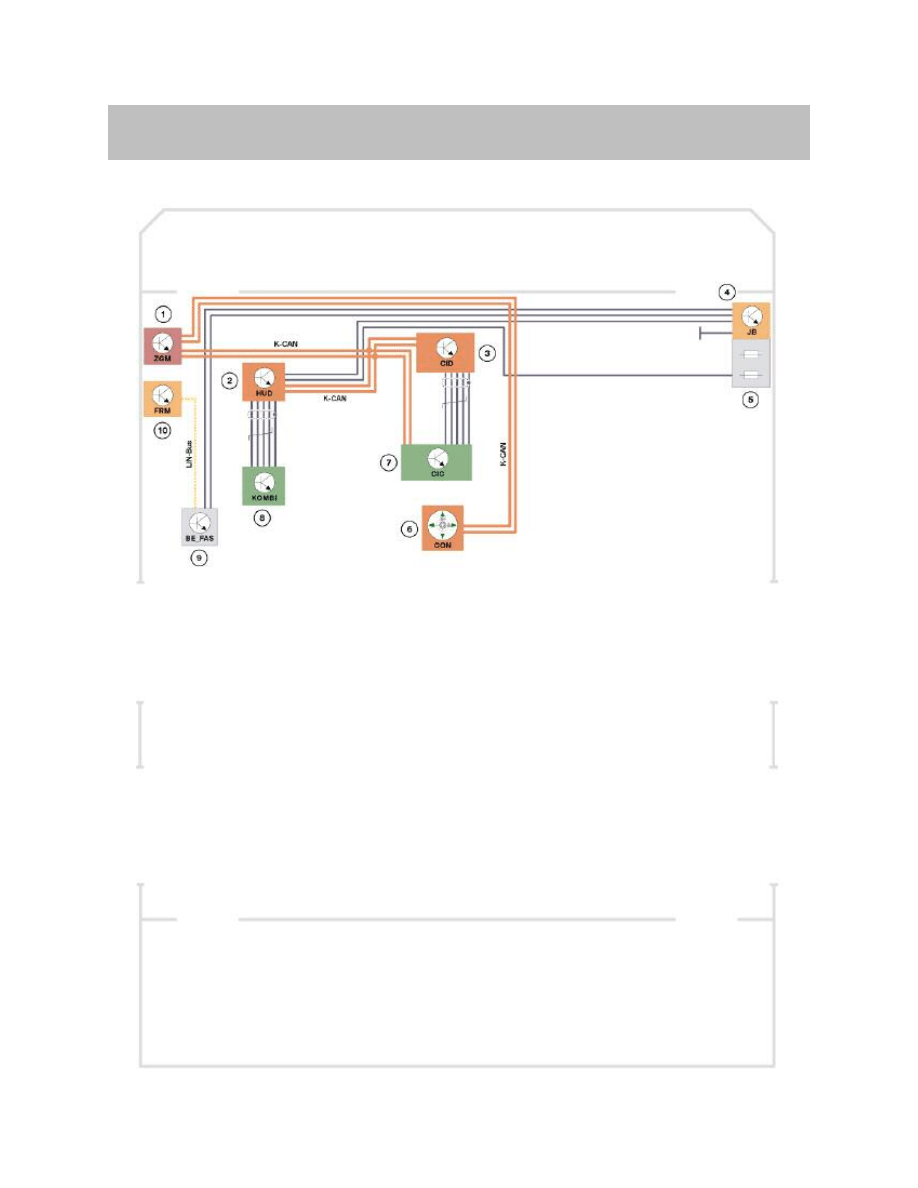
Head-up Display System Schematic Circuit Diagram
6
F01 Head-up Display
System Overview

K-CAN signals to HUD control unit
7
F01 Head-up Display
Index
Explanation
Index
Explanation
1
Central Gateway Module (ZGM)
7
Car Information Computer (CIC)
2
Head-up display (HUD)
8
Instrument cluster (KOMBI)
3
Central Information Display (CID)
9
Driver assistance system control panel (BAFAS)
4
Junction box (JB)
10
Footwell module (FRM)
5
Front power distribution box
K-CAN
Body controller area network
6
Controller
LIN-Bus
Local Interconnect Network bus
In/out
Information
Source/sink
Function
In
Road speed
Instrument cluster
Display in the HUD
In
Check control message
Instrument cluster
Display in the HUD
In
Dimming/ brightness
Rain and driving light sensor (RLS)
via roof function Center (FZD)
Brightness adjustment
In
Height adjustment
CIC
Height adjustment
In
Brightness offset
CIC
Brightness adjustment
In
DCC
EHB3
(Adaptive Brake Assistant Warning)
Display in the HUD
In
Function selection
CIC
What is displayed in the HUD
In
On/Off switch
BAFAS
Switching the HUD On/Off
In
Navigation
CIC
Display in the HUD
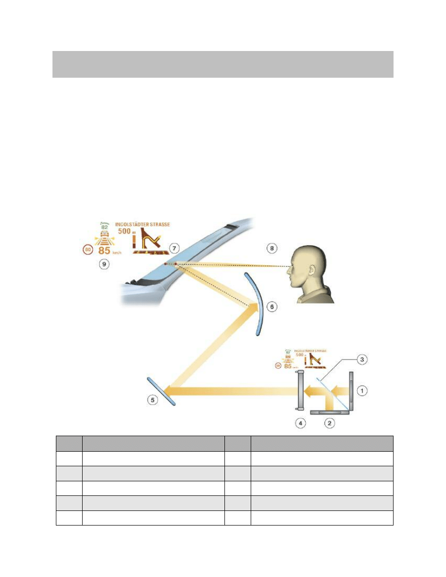
The Principle
The HUD can be compared to a projection device. A light source is required to project
the HUD information. The two LED arrays (red and green) serve as the light source. The
image content is created by the TFT projection display. The TFT projection display can
be compared to a filter which admits or blocks light.
An optical imaging element determines the shape, distance and size of the HUD
images.
The image appears to float freely over the road, the windshield acts as a deflecting mir-
ror.
8
F01 Head-up Display
System Functions
Index
Explanation
Index
Explanation
1
LED array, green
6
Curved mirror
2
LED array, red
7
Windshield
3
Transparent mirror
8
Observer's point of vision
4
TFT projection display
9
Projected image
5
Plane mirror
Principle of the head-up display
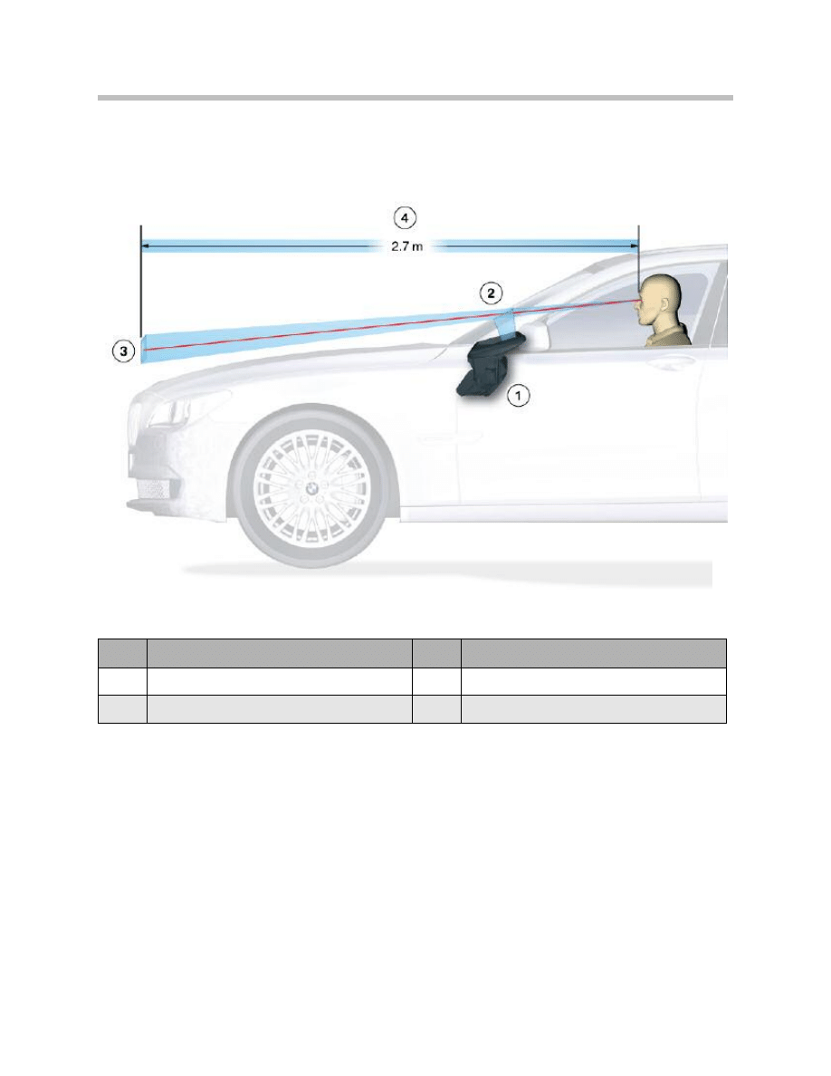
Projection Distance
The projected HUD image content appears at a distance of approximately 2.7 m from the
observer’s eye.
9
F01 Head-up Display
Index
Explanation
Index
Explanation
1
Head-up display
3
Projected Image
2
Windshield
4
Projected distance
Projection distance
Switch-on Conditions
The following conditions are required to release the light:
• Terminal 15 ON
• Button (HUD) pressed on the driver assistance system control panel, BEFAS.
Switch-on Performance
The HUD receives the terminal 30 ON status via the K-CAN. The HUD is partially ready
for operation from terminal R ON. That means that:
• The HUD can communicate with the other electrical-system devices via the K-CAN
• The TFT projection display is initialized and blanked
• The LEDs are off.
The HUD receives the terminal 15 ON status via the K-CAN. The HUD is ready for opera-
tion from terminal 15 ON. This permits the following actions:
• Switching on of the backlighting by the button on the BAFAS
• HUD height adjustment
• Adjustment of HUD brightness
• Display of information via the HUD.
When the vehicle is started, the vehicle is set to terminal 50 status. In terminal 50, i.e.
Lights Off, the HUD goes into a hold status. This hold status is maintained until shortly
after the end of the terminal 50 status.
10
F01 Head-up Display
ON/OFF button on the BAFAS
Switch-off Conditions
The HUD is switched off under the following conditions:
• Button on the BAFAS pressed
• Terminal R OFF
Brightness Offset
Brightness offset is a PIA Personal Profile function. Brightness offset allows the customer
to set and save his/her own individual HUD default brightness setting. Each time the HUD
is switched on, this setting is used as the brightness offset for the HUD.
The brightness setting is adjusted with the controller via the CID. Any value between -10
and +10 can be set. The mid-position value is 0.
The value is transferred via the K-CAN to the HUD.
The brightness setting is automatically corrected in order to compensate for different
light conditions. Compensation is based on signals from the rain and light sensor.
The automatic brightness setting is configured in such a way that no HUD brightness
jumps occur.
11
F01 Head-up Display
Brightness setting
The differing light conditions depend, for instance, on:
• Environmental conditions, such as day, night, sunshine, clouds, rain, fog, snow, etc.
• Surrounding structural features, such as tunnels, underground car parks, etc.
• The driver can adjust the brightness of the instrument lighting with the knurled
wheel.
• From terminal 58g lights on, the HUD brightness is determined by the brightness
setting of the instrument lighting.
The brightness is dependent on the following conditions:
• Dimmer-wheel setting
• Brightness offset
• Rain/light sensor, RLS
Operating-hours Counter
The HUD incorporates individual service-time counters for the HUD and the LED arrays.
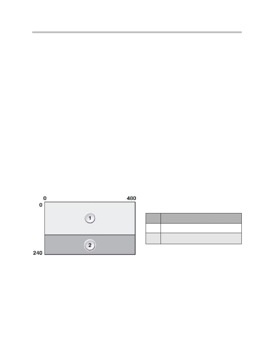
Display Area of Head-up Display
The HUD size is approximately 200 mm x 100 mm with a display resolution of 480 x 240
pixels. The HUD is separated into 2 display areas. The individual fields are “optically” sep-
arated in the image so that they can be identified more easily.
The upper area shows navigation information and CC messages in the form of symbol,
bar display and text.
The lower area shows speed-related displays in the form of unit, current speed and
cruise control.
12
F01 Head-up Display
Index
Explanation
1
Navigation/CC display area
2
Road speed/Cruise control display area
Display area in the head-up display

Color Selection
Symbols (such as e.g. warning symbols) are specified by the individual control units. The
color specifications are adopted by the instrument cluster for display and representation
on the HUD.
“Flat” 2D symbols are used for optimum visibility and readability.
The colors are:
• Orange as the standard color
• Red or yellow for warning messages
• Green for the set speed
• The HUD background is transparent
13
F01 Head-up Display
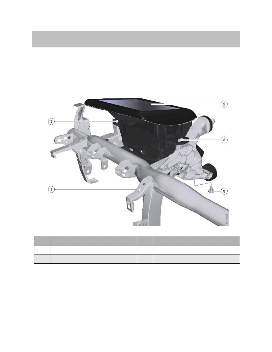
The head-up display is fitted above the steering column, immediately behind the instru-
ment cluster. It is fastened to the bulkhead supporting structure by three hexagon-head
bolts.
14
F01 Head-up Display
System Components
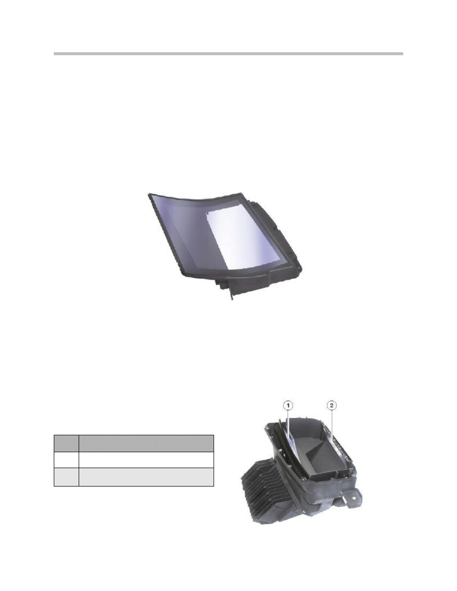
Index
Explanation
Index
Explanation
1
Carrier bracket
3
Hexagon bolt
2
Head-up display HUD
Location of head-up display (HUD) in F01/F02

The head-up display comprises the following components:
• Cover glass
• Mirrors
• 2 LED arrays
• TFT projection display
• PCB
• Housing
The following components are required in addition to the components listed above:
• Windshield
• Light module and BEFAS
• Rain/light sensor
• Roof function Center and junction box
• HUD trim
The following controls are required to operate the HUD:
• On/Off button on the BEFAS
• Light switch in the light switch cluster
• Instrument-lighting dimmer
• Controller
15
F01 Head-up Display
Cover Glass
The cover glass is made from scratch-resistant, coated polycarbonate (PC) and forms the
top cover of the HUD. The cover glass protects the interior of the HUD against dust and
objects accidentally placed on it.
The glass combined with the HUD trim are curved so that any incident light is not reflect-
ed back to the driver.
It also guarantees unobstructed projection of the display information onto the windshield
without interference from stray light effects, for instance.
Mirrors
Two mirrors are fitted in the head-up display. They reflect the information in the display
onto the windshield.
The concave mirror (1) is responsible for compensating for the curvature of the wind-
shield and for the size and distance of the image.
The flat mirror (2) is a deflecting mirror to keep the beam in the space provided.
The convex mirror is made of plastic while
the flat mirror is made of glass.
16
F01 Head-up Display
Plane mirror
Mirrors in the HUD
Index
Explanation
1
Curved mirror
2
Plane mirror
LED Array
There are two LED arrays. The LED array is an arrangement of LEDs in one plane and
acts as the back lighting for the TFT projection display. The LED array generates the light
required for the HUD brightness. The LED arrays consist of red and green LEDs. The
LEDs generate the brightness of the HUD content as controlled by the master PCB.
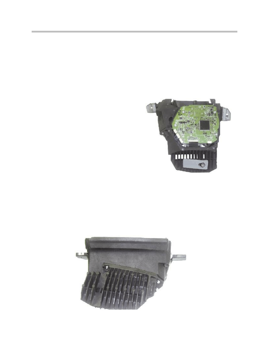
PCB
The following components among others are
incorporated on the PCB:
• K-CAN interface
• Processor (CPU)
• LVDS controller
• EEPROM memory
• Power supply
The video signals are passed on to the display
by the instrument cluster via an LVDS lead.
Housing
The casing is made of aluminum and consists of a bottom section and the plastic cover.
The (aluminum) cooling fins and the electrical power supply are attached to the bottom
section. The cover glass is integrated into the cover.
17
F01 Head-up Display
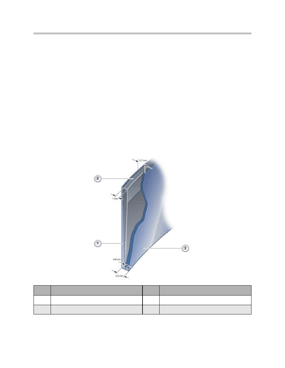
Windshield
The windshield is a “special design” that is essential for projection of the displays. The
outer and inner glass panes are bonded to a plastic film, just like in the standard wind-
shield. Unlike in the standard windshield, this plastic film is not parallel but is tapered over
the entire area of the windshield.
The taper prevents the HUD from displaying images twice. The taper tip points down-
wards and starts at a distance of approximately 10 cm to the bottom edge of the wind-
shield.
The end of the taper is located at approximately 2/3 windshield height. In the top third of
the windshield, the plastic film runs parallel to the outer and inner glass panes. The thick-
ness of the taper tip is 0.8 mm. The thickness of the end of the taper is 1 mm.
The total thickness of the bottom edge of the windshield is 4.5 mm. The total thickness
of the top edge of the windshield is 4.7 mm.
18
F01 Head-up Display
Index
Explanation
Index
Explanation
1
Outer glass pane
3
Inner glass pane
2
Plastic film
mm
Unit of measurement in mm
Windshield
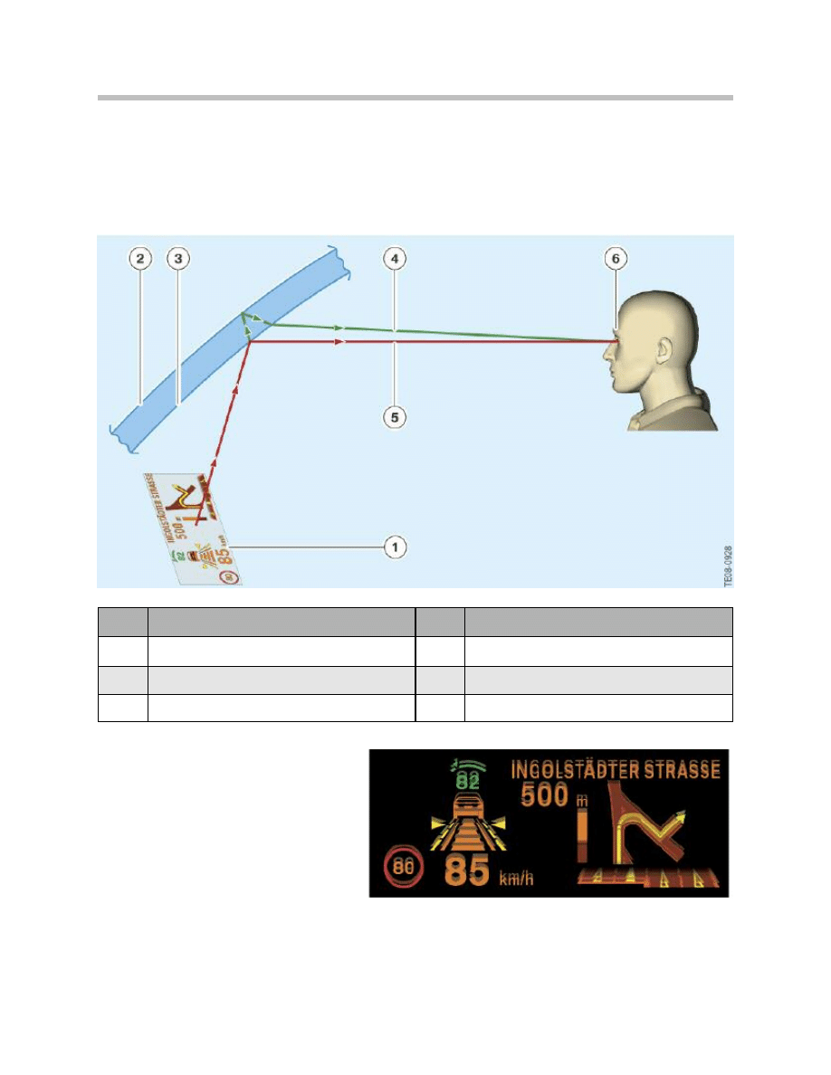
Incorrect Windshield Fitted
The HUD image is always reflected on the These two images are overlaid by the angle of
inner surface and outer surface of the taper in the HUD screen, so that the driver wind-
shield only sees “one” image.
Because of the angle of tilt of the
glass in a standard windshield, the
two reflected images are offset
against one another.
The illustration below shows the
result when a Rain/light sensor stan-
dard windshield is fitted.
19
F01 Head-up Display
Double reflection
Index
Explanation
Index
Explanation
1
Display
4
Reflection on the outer surface of the windshield
2
Outer surface of the windshield
5
Reflection on the inner surface of the windshield
3
Inner surface of the windshield
6
Double display by HUD
The rain and light sensor provides the brightness signal over the LIN bus to the roof func-
tion Center FZD and then to the K-CAN.
Eyebox
The eyebox is the movement space in which the driver can move without his view of the
image in the HUD being impaired.
The freedom of movement within the eyebox is roughly:
• 70 mm vertically plus ± 30 mm range of adjustment
• 130 mm horizontally.
The HUD image is not clearly visible outside the eyebox limits.
20
F01 Head-up Display
Index
Point of vision
HUD image
1
Within the eyebox
Optimum illumination of the image
2
Offset to the left
Image cut off on the left
3
Offset to the right
Image cut off on the right
Eyebox, shift to the left/to the right
Instrument Cluster
For the purposes of filtering the speed reading, a distinction is made between accelera-
tion, braking and coasting phases.
When the car is in the coasting phase, 3 successive values are averaged and then the
speed is updated.
Check Control Messages
All CC messages are also displayed on the HUD. The instrument cluster has the master
function for the messages. The symbol together with the associated text is transmitted by
the instrument cluster. CC messages are given precedence over the display of other
information such as navigation-system directions, for instance.
Note: A Check Control message is displayed for 8 seconds. If several CC
messages occur simultaneously, each one is displayed for 3 seconds.
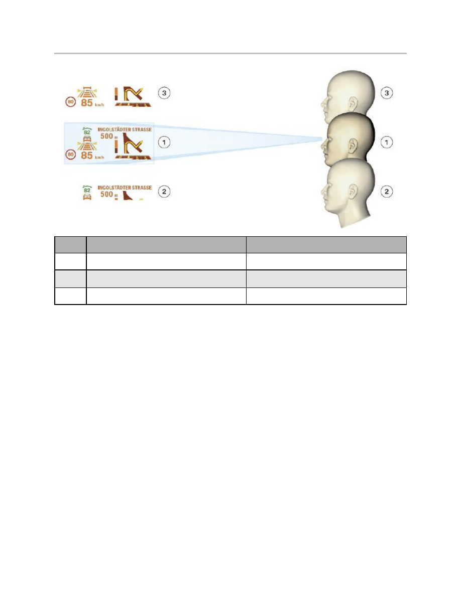
21
F01 Head-up Display
Index
Point of vision
HUD image
1
Within the eyebox
Optimum illumination of the image
2
Offset downwards
Image cut off at the bottom
3
Offset upwards
Image cut off at the top
Eyebox, shift upwards/downwards
Controls
The following controls are used in the operation of the HUD:
• ON/OFF button on the BEFAS
• Dimmer wheel in the light switch cluster
• Controller.
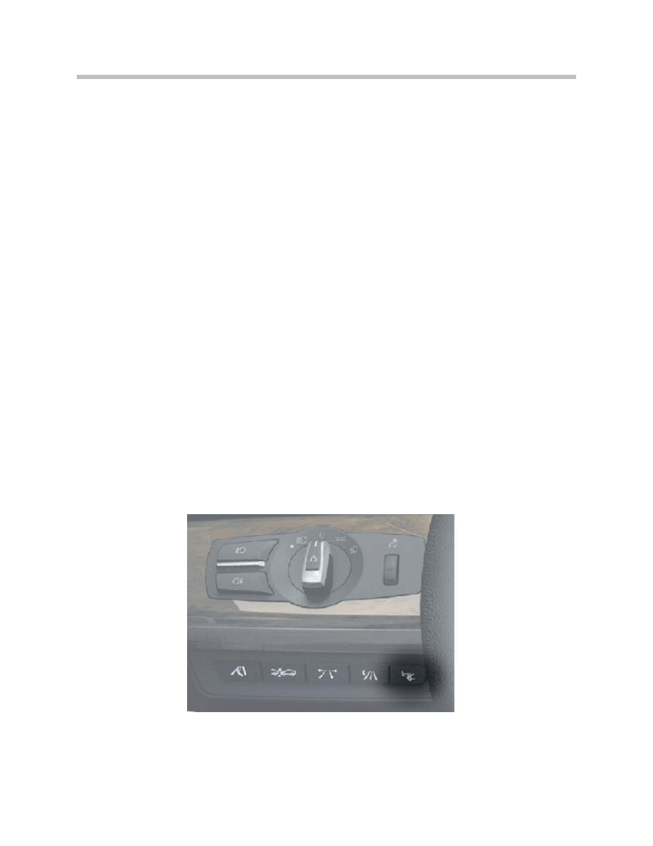
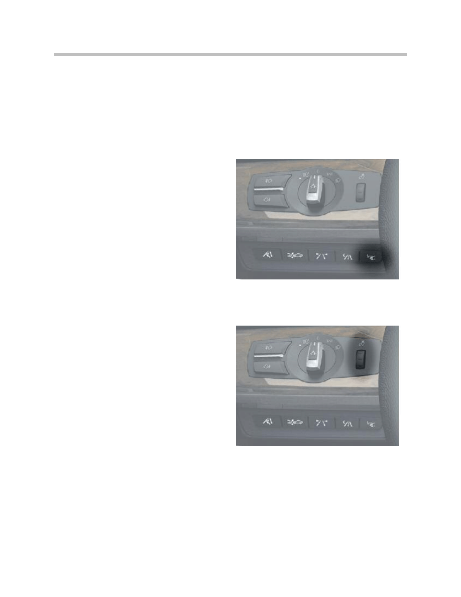
Driver Assistance System Control Panel
The HUD On/Off button is located on the
BEFAS. The button is resistance-coded and
routed directly to the HUD. The HUD can
identify the button signals or a button fault
using the resistance coding.
Instrument-lighting Dimming
The dimmer setting is also used for the HUD
with active headlights. The dimmer signal is
emitted by the light module.
Controller
The HUD brightness and height settings are adjusted with the Controller via the CID.
Brightness setting is also termed brightness offset.
Functions such as e.g. navigation can also be set with the Controller in the Function
selection menu. Therefore these settings have an indirect effect on the HUD display.
22
F01 Head-up Display
ON/OFF button on the BEFAS
Instrument-lighting dimming
The following information for the technician is described in this section:
• Adjusting the brightness
• Adjusting the height of the horizon on the HUD
• Vertical rotation of the image
• Test functions
• Replacing the HUD
• HUD
• Diagnostics
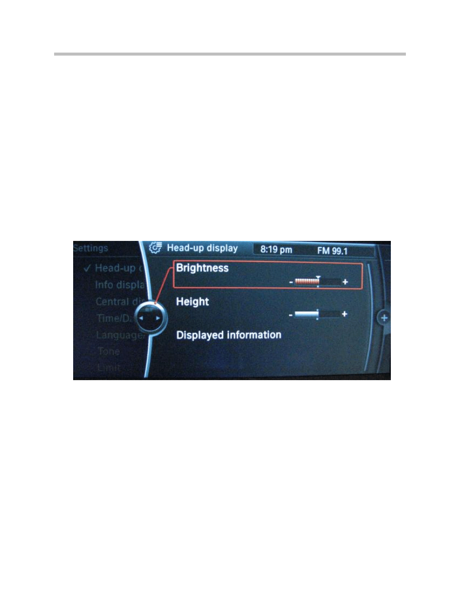
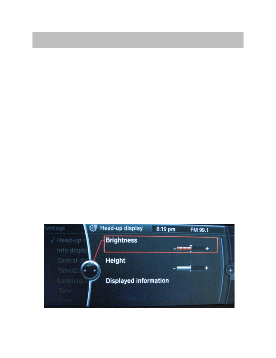
Adjusting the Brightness
The brightness of the HUD can be individually adjusted. The CID is the display instru-
ment and the controller the control element for brightness adjustment.
The brightness is set as follows:
• Call up the main menu by pressing the menu button.
• Press the Controller and select the menu option “Settings”.
• Turn the Controller until “Head-up display” is selected on the menu bar and then
press the Controller to confirm selection.
• Turn the Controller until “Brightness” is selected and then confirm.
• Set the desired brightness by turning the Controller and confirm by pressing.
23
F01 Head-up Display
Service Information
Adjusting the brightness
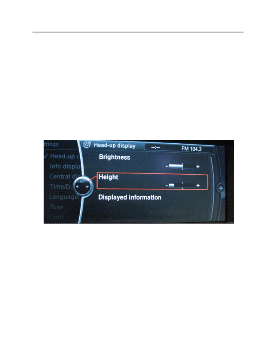
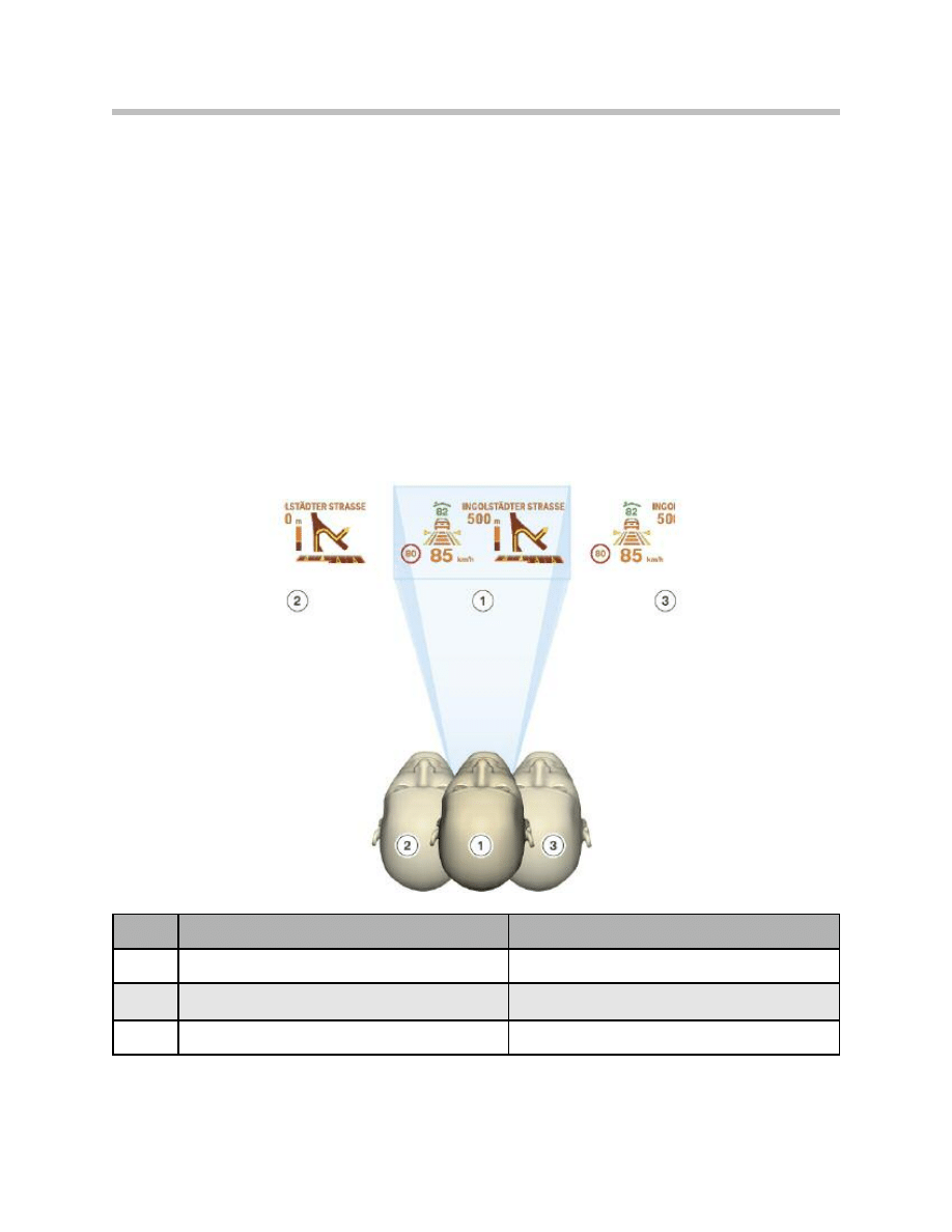
Adjusting the Height of the Horizon on the HUD
On the BMW 7 Series F01/F02, the driver can adjust the location of the image and the
eyebox to suit his/her particular requirements using the iDrive controller.
The eyebox can be shifted up to a maximum of ± 30 mm upwards or downwards.
The height setting is adjusted as follows:
• Call up the main menu by pressing the menu button.
• Press the Controller and select the menu option “Settings”.
• Turn the Controller until “Head-up display” is selected and then press the Controller
to confirm selection.
• Turn the Controller until “Height setting” is selected and then press to confirm.
• Set the desired height by turning the Controller and confirm by pressing.
Note: The height can only be adjusted when the HUD is active.
The height adjustment is in the scope of the PIA. The setting is stored in the EEPROM
for each key. If the signal “Radio remote key status” is received when Terminal 30 is on,
the mirror moves to the position set for the current key.
The mirror remains in that position as long as the HUD is switched on.
Vertical Rotation of the HUD
The HUD is supplied as standard with a defined basic setting. The HUD image can be
rotated in the horizontal by a service technician using vertical rotation, after a change of
windshield, for instance.
The display is adjustable within a range of -3° to +3° by means of a motor.
Detailed information may be found in the BMW diagnostic system.
24
F01 Head-up Display
Test Functions
Calling/quitting Test Functions
Certain test functions may be also invoked directly on the HUD without using a BMW
diagnostic system, as follows:
• Press and hold the button on the BEFAS for approximately 20 seconds and then
release.
• Call up further test functions by pressing the button again.
• To exit this function, press and hold the button on the BEFAS for more than 20
seconds.
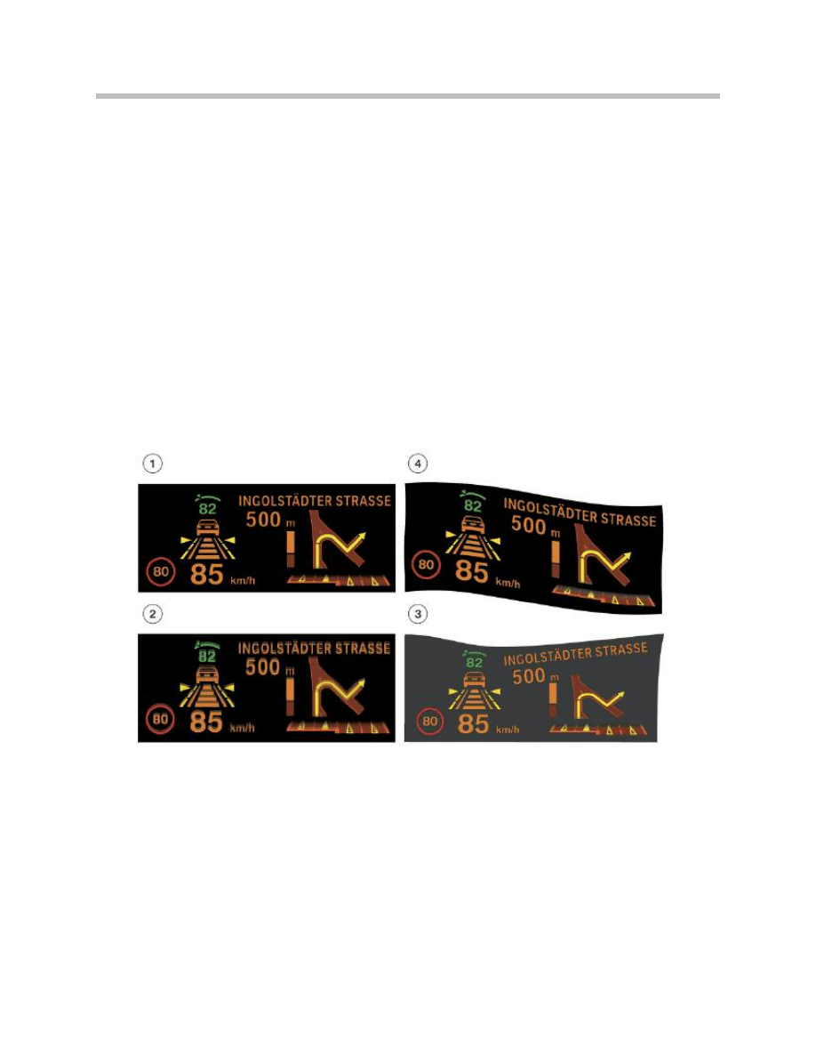
Replacing the HUD
Image Defects
Incorrect installation of the HUD or of the windshield may result in faulty HUD projections.
HUD Image defects are explained as follows:
• Image 1 is compressed, (windshield installed incorrectly)
• Image 2 is duplicated, (wrong windshield installed)
• Images 3 and 4 are distorted, the HUD has been fitted incorrectly
25
F01 Head-up Display
HUD image defects
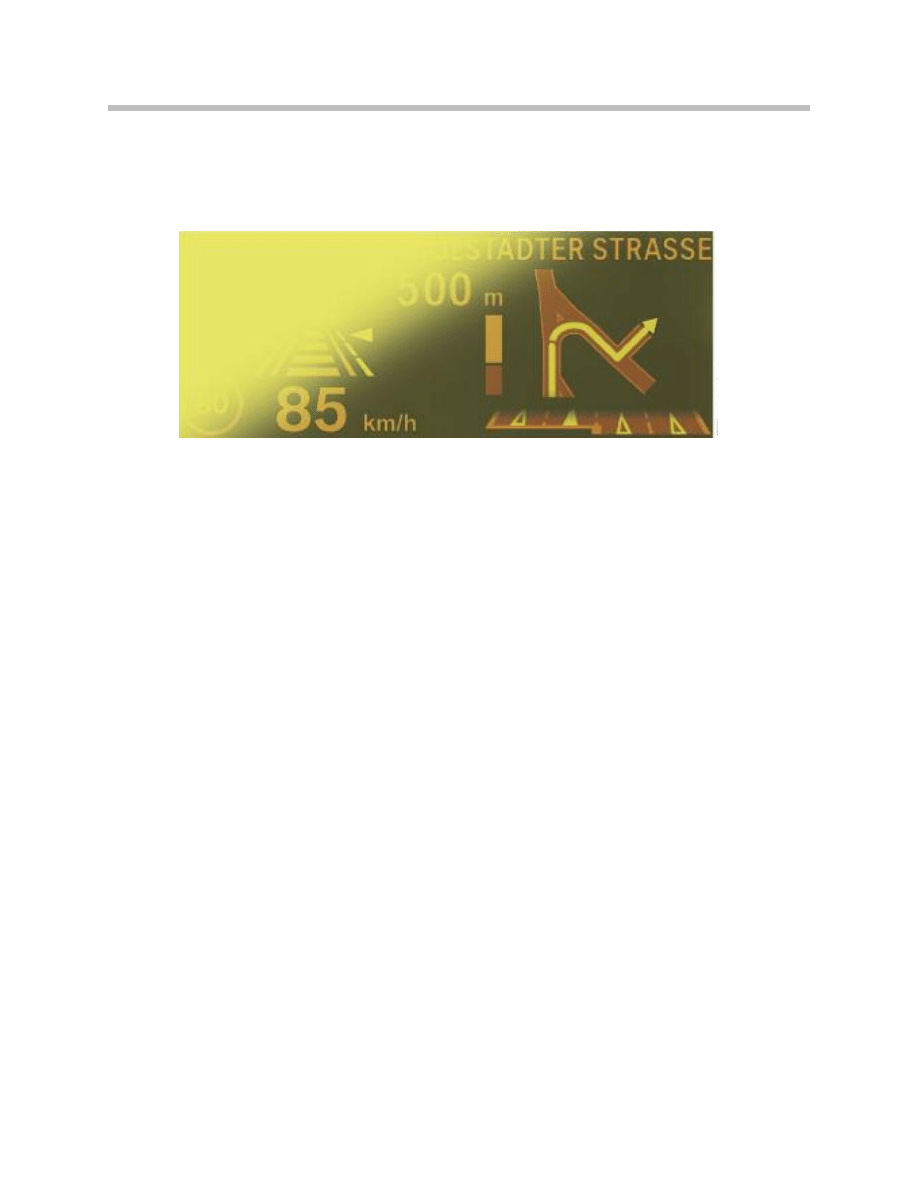
The image is blanked out by light striking the windshield or the HUD in unfavorable light
conditions. Excessive heat in the HUD will also cause the image to fade.
Correcting Distortion (Warping)
Should the image be distorted after a change of windshield, the image display can be
improved using the Warping function. Warping is the technical term for the improvement
of the image display.
Detailed information on the subject of warping can be found in the BMW diagnostic
system.
Diagnosis
The most important functions for service can be called up in diagnosis.
These functions are:
• Initiate self-test
• Read out fault memory
• Delete fault memory
• Read out status
• Specify status
The following errors/faults are stored in the HUD and can be
read out with the aid of the diagnosis program:
• Communication faults with the connected bus systems
• Internal HUD faults
26
F01 Head-up Display
Image defect caused by incident light or overheating in the HUD

Sleep Mode
The following functions are possible in sleep mode:
• Terminal 30b OFF,
- HUD is switched off completely
• Terminal 30b ON,
- Monitor K-CAN
• Terminal R soft,
- Display and LED array off
- Switch query
- Diagnostics
- System test (no display of test cards)
- Flash program
- Output data to the display
• Terminal 15 soft,
- LED array on
27
F01 Head-up Display
Document Outline
- Main Menu
- 01_F01 Introduction
- 02_F01 Powertrain
- 03_F01 Voltage Supply & Bus Systems
- 03.1_F01 Bus Systems
- 03.2_F01 Voltage Supply
- 03.3_F01 Energy Management
- 03.4_F01 Car Access System 4
- 04_F01 Chassis Dynamics
- 04.1_F01 Chassis and Suspension
- 04.2_F01 Dynamic Driving Systems
- 04.3_F01 Longitudinal Dynamics Systems
- 04.4_F01 Lateral Dynamics Systems
- 04.5_F01 Vertical Dynamics Systems
- 04.6_F01 Cruise Control Systems
- 05_F01 General Vehicle Electronics
- 05.1_F01 Comfort Access
- 05.2_F01 Central Locking System
- 05.3_F01 Automatic Soft Close
- 05.4_F01 Power Windows
- 05.5_F01 Sliding Tilting Sunroof
- 05.6_F01 Anti-theft System
- 05.7_F01 Automatic Luggage Compartment Lid
- 05.8_F01 Exterior Lighting
- 05.9_F01 Interior Lighting
- 05.10_F01 Wiper-Washer System
- 05.11_F01 Exterior Rear View Mirrors
- 05.12_F01 Seats
- 05.13_F01 Steering Column Switch Cluster
- 06_F01 Driver Information Systems
- 06.1_F01 Displays Indicators and Controls
- 06.2_F01 Head-up Display
- 06.3_F01 BMW Night Vision 2
- 06.4_F01 Active Blind Spot Detection System
- 06.5_F01 KAFAS
- 06.6_F01 PDC-TRSVC
- 07_F01 Information and Communication Technology
- 07.1_F01 Rear Seat Entertainment Systems
- 07.2_F01 Telephone System
- 07.3_F01 Voice Activation System
- 07.4_F01 Audio Systems
- 08_F01 Climate Control
- 09_F01 Passive Safety Systems
- 10_F01 Service Information
- 10.1_F01 System Functions
- 10.2_ISTA-Programming
Wyszukiwarka
Podobne podstrony:
06 E70 Head Up Display WB
06b E70 Head up Display
15a Head Up Display
06 1 F01 Displays Indicators and Controls
Head up opis pinów
06 5 F01 KAFAS
06 3 F01 BMW Night Vision 2
06 4 F01 Active Blind Spot Detection System
Head Up demontaż
06 6 F01 PDC TRSVC
Michael Jackson Keep Your Head Up
06 W górę! Up Yours marzec 2008
06 F10 Displays, Indicators and Controls
MT st w 06
więcej podobnych podstron