BMW�Service
F10�Displays,�Indicators�and�Controls

General�information
Symbols�used
The�following�symbol�/�sign�is�used�in�this�document�to�facilitate�better�comprehension�and�to�draw
attention�to�particularly�important�information:
Contains�important�safety�guidance�and�information�that�is�necessary�for�proper�system�functioning
and�which�it�is�imperative�to�follow.
Information�status�and�national-market�versions
The�BMW�Group�produces�vehicles�to�meet�the�very�highest�standards�of�safety�and�quality.�Changes
in�terms�of�environmental�protection,�customer�benefits�and�design�make�it�necessary�to�develop
systems�and�components�on�a�continuous�basis.�Consequently,�this�may�result�in�differences�between
the�content�of�this�document�and�the�vehicles�available�in�the�training�course.
As�a�general�principle,�this�document�describes�left-hand�drive�vehicles�in�the�European�version.�Some
controls�or�components�are�arranged�differently�in�right-hand�drive�vehicles�than�those�shown�on�the
graphics�in�this�document.�Further�discrepancies�may�arise�from�market‐specific�or�country-specific
equipment�specifications.
Additional�sources�of�information
Further�information�on�the�individual�topics�can�be�found�in�the�following:
•
in�the�Owner's�Handbook
•
in�the�integrated�service�technical�application
©2009�BMW�AG,�Munich,�Germany
Reprints�of�this�publication�or�its�parts�require�the�written�approval�of�BMW�AG,�Munich
The�information�in�the�document�is�part�of�the�BMW�Group�technical�training�course�and�is�intended
for�its�trainers�and�participants.�Refer�to�the�latest�relevant�BMW�Group�information�systems�for�any
changes/supplements�to�the�technical�data.
Information�status:�December�2009

F10�Displays,�Indicators�and�Controls
Contents
1.
1
1.1.
1
2.
2
2.1.
2
2.1.1.
2
2.1.2.
2
2.1.3.
3
2.2.
4
2.2.1.
CID�with�10.2"�screen�diagonal
4
2.2.2.
5
2.3.
5
2.4.
6
2.5.
Controls�on�the�steering�wheel
7
2.6.
Operating�controls�in�the�center�console
8
2.7.
Driver�assistance�systems�operating�unit
9

F10�Displays,�Indicators�and�Controls
1.�System�Overview
1
1.1.�Introduction
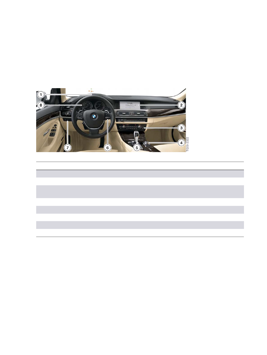
As�in�all�other�BMW�models,�the�operating�and�control�concept�of�the�new�BMW�5�Series�F10�is�based
on�clear�and�optimum�structuring�of�the�cockpit.�A�reduced�number�of�switches�simplifies�the�logical
operation.�The�display,�indicator�and�control�elements�are�organized�in�a�hierarchical�arrangement
corresponding�to�their�function.
F10�Overview�of�the�display,�indicator�and�control�elements
Index
Explanation
1
Head-up�display�HUD
2
Central�Information�Display,�CID
3
Favorite�buttons�for�individual�assignment�and�operation�of�the�heating�and�air
conditioning�system
4
Controller�CON
5
Gear�selector�switch�GWS
6
Steering�wheel�buttons
7
Driver�assistance�systems�operating�unit
8
Instrument�cluster�KOMBI
F10�Displays,�Indicators�and�Controls
2.�System�Components
2
2.1.�Instrument�cluster
The�instrument�panel�receives�information�on�the�wiring�harness�in�the�form�of�analog�and�digital
electrical�signals.�These�signals�are�processed�and�displayed�in�the�instrument�panel�or�passed�on�as
information�to�other�control�units.
As�a�control�unit,�the�instrument�panel�is�a�bus�device�in�the�MOST�bus�and�in�the�powertrain�CAN.
2.1.1.�Basic�instrument�panel
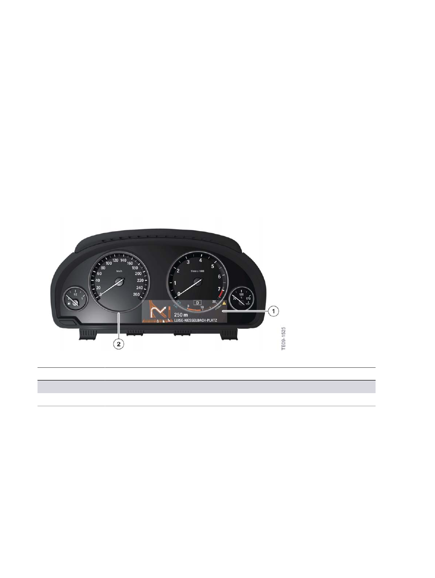
The�basic�instrument�panel�already�familiar�from�the�F07�is�used�in�all�versions�of�the�F10.�A�TFT
display�with�a�resolution�of�640�x�160�pixels�is�located�in�the�basic�instrument�panel�under�the�round
instruments.�It�has�a�screen�diagonal�of�5.7".�The�round�instruments�are�always�surrounded�by�a
closed�ring.
F10�Basic�instrument�panel�(Not�US)
Index
Explanation
1
TFT�display
2
Closed�instrument�ring
2.1.2.�Brake�energy�display
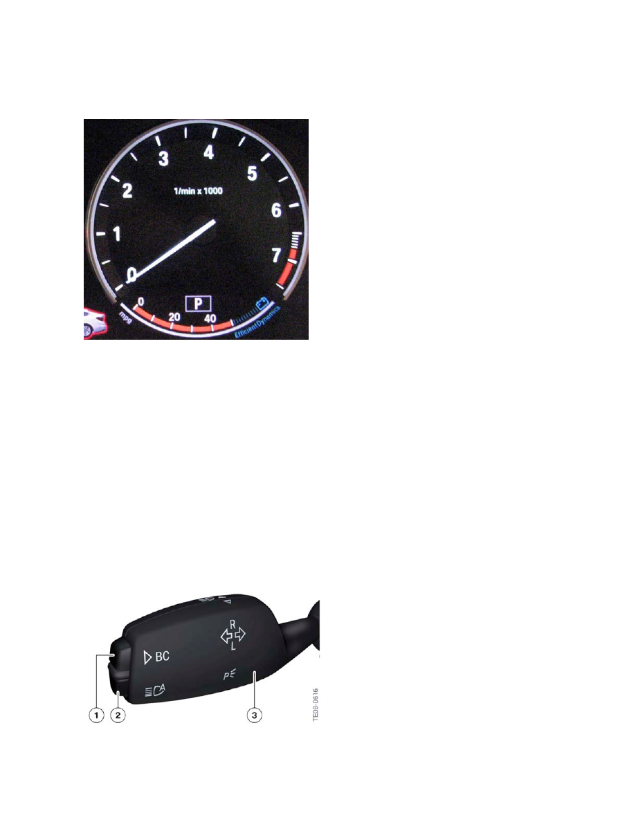
The�F10�comes�standard�with�Brake�Energy�Regeneration.�Brake�Energy�Regeneration�transforms
the�vehicle’s�kinetic�energy�into�electricity,�and�uses�this�power�to�charge�the�battery.�As�a�result,�the
battery�draws�less�power�from�the�engine,�and�fuel�consumption�is�reduced.
The�kinetic�energy�of�the�vehicle�is�converted�into�electrical�energy�while�the�vehicle�is�in�coasting
mode�or�under�braking.�The�battery�is�partially�charged�and�the�fuel�consumption�can�be�reduced.
The�blue�indicator�in�the�instrument�panel�below�the�tachometer,�which�lights�up�whenever�kinetic
energy�is�converted�into�electricity�(while�coasting�off�the�accelerator�or�under�braking).�The�red
section�of�the�display�below�the�“P”�is�the�mile�per�gallon�gauge.
F10�Displays,�Indicators�and�Controls
2.�System�Components
3
F10�Current�fuel�consumption�display�in�coasting�(overrun)�mode
2.1.3.�On-board�computer
The�on-board�computer�functions�can�be�called�up�by�briefly�pressing�the�on-board�computer�button
on�the�steering�column�switch.
Pressing�the�on-board�computer�button�again�displays�information�in�the�following�order:
•
Range
•
Average�fuel�consumption
•
Average�speed
•
Distance�(with�activated�route�guidance)
•
Estimated�time�of�arrival�(with�activated�route�guidance)
•
Date
•
Road�sign�recognition.
F10�Buttons�on�the�steering�column�switch

F10�Displays,�Indicators�and�Controls
2.�System�Components
4
Index
Explanation
1
Button�for�on-board�computer
2
High-beam�assistant�button
3
Steering-column�switches
More�detailed�information�can�be�found�in�the�current�vehicle�owner's�manual�for�the�BMW�5�Series.
2.2.�Central�Information�Display
Depending�on�the�equipment,�two�different�versions�of�the�Central�Information�Display�CID�are
installed�in�the�F10.
As�on�all�new�BMW�models,�the�system�is�operated�by�means�of�the�central�control�element,�the
controller.
The�central�information�display�is�an�integrated�display�and�operating�unit�for�the�following�functions:
•
Audio�functions,�for�example�radio,�CD,�MP3
•
Telephone�and�data�services
•
On-board�computer,�journey�computer
•
Vehicle�info,�integrated�operating�instructions�IBA
•
Heating�and�air�conditioning�system
•
Personalized�features,�for�example�radio�station�selection
•
Vehicle�functions,�for�example�PDC�and�EDC
•
BMW�Services.
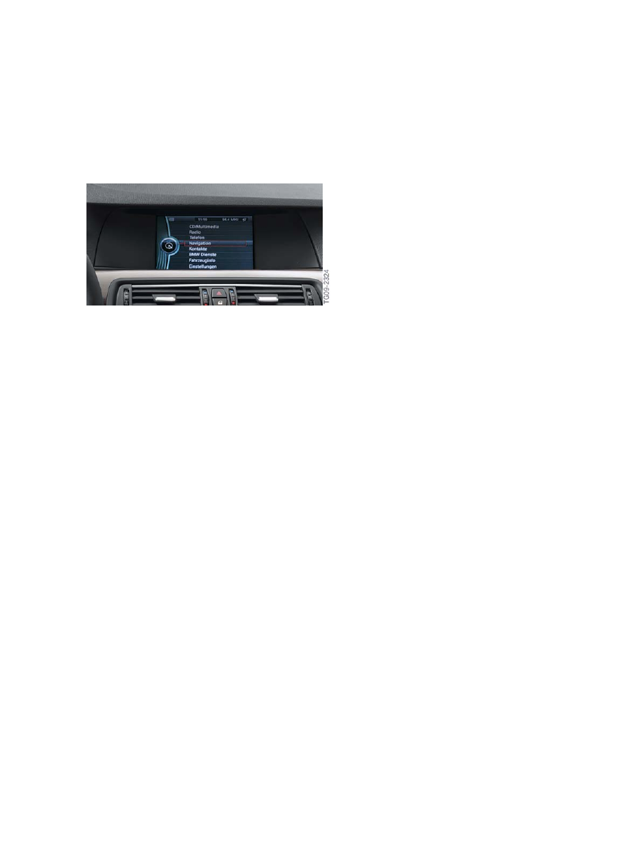
2.2.1.�CID�with�10.2"�screen�diagonal
In�conjunction�with�the�Navigation�system�(option�609),�a�CID�with�10.2"�screen�diagonal�is�installed.
The�resolution�of�the�display�is�1280�x�480�pixels.
F10�CID�with�10.2"�screen�diagonal
F10�Displays,�Indicators�and�Controls
2.�System�Components
5
2.2.2.�CID�with�7"�screen�diagonal
In�conjunction�with�a�vehicle�configuration�without�a�navigation�system,�a�CID�with�7"�screen�diagonal
is�installed.�The�resolution�of�this�display�is�800�x�480�pixels.
F10�CID�with�7"�screen�diagonal
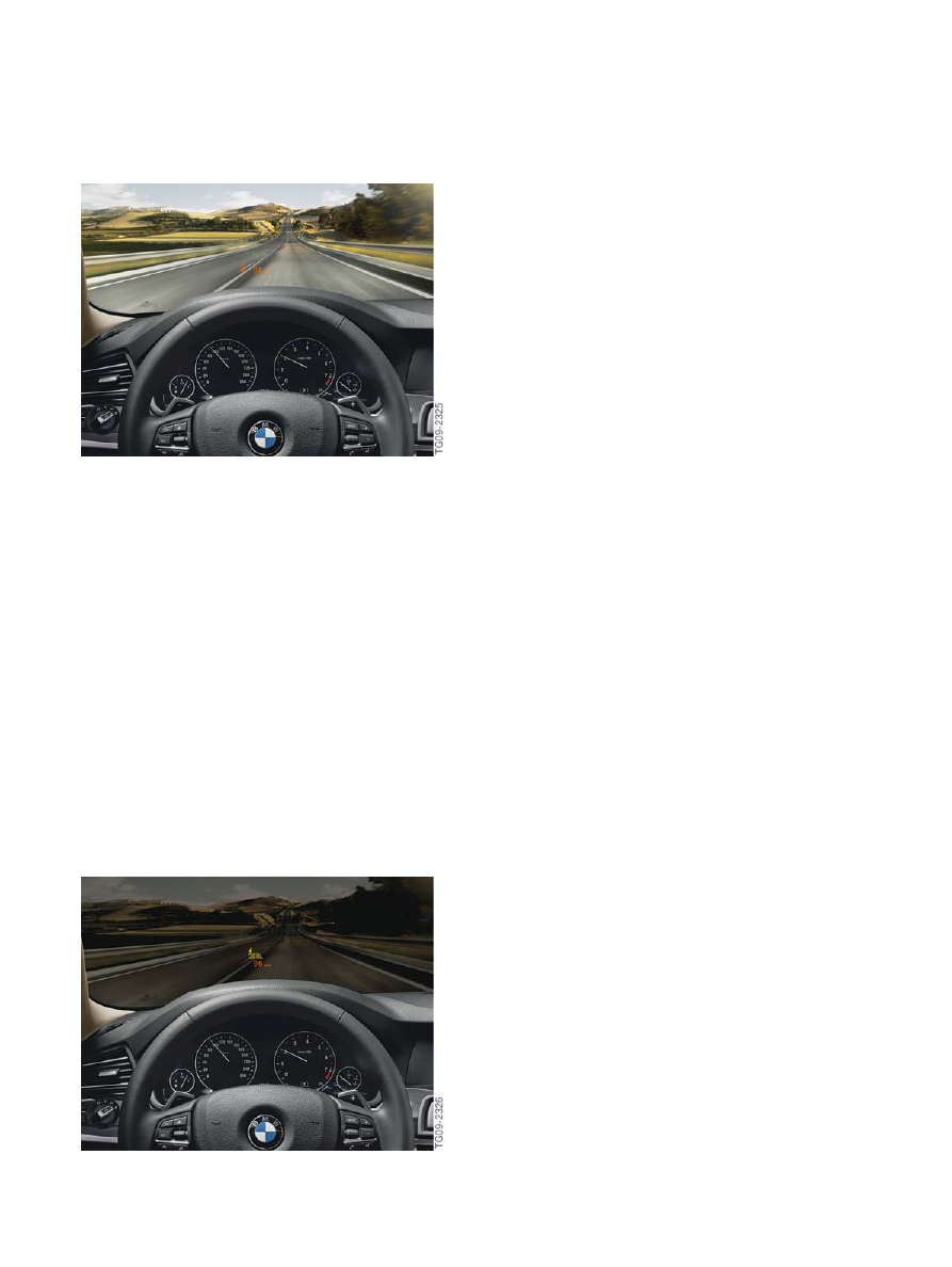
2.3.�Head‐Up�Display
The�very�name�"Head‐Up"�describes�the�principle�benefit�of�this�system.�The�Head‐Up�Display�HUD
projects�a�virtual�image�into�the�driver's�field�of�vision.�Important�information�such�as�cruise�control
details�or�arrow�displays�from�the�navigation�system�are�projected�onto�the�windscreen�and�are�thus
permanently�visible�within�the�driver's�field�of�view.
The�head‐up�display�(option�610)�in�the�F10�contains�various�functions�aimed�at�enhancing�road
safety�and�driving�comfort.
The�head-up�display�includes�the�following:
•
the�Dynamic�Cruise�Control�DCC
•
the�Active�Cruise�Control�with�Stop�&�Go�function
•
the�collision�warning�with�brake�application�function
•
information�from�the�navigation�system
•
Check�Control�messages
•
road�speed.
Having�the�displays�in�the�driver's�direct�field�of�view�increases�safety,�as�the�eyes�are�always�on�the
traffic.
F10�Displays,�Indicators�and�Controls
2.�System�Components
6
F10�Head-up�display
For�more�information�on�the�head-up�display,�refer�to�the�F01�entitled�"Head-Up�Display�HUD"�training
material�available�on�TIS�and�ICP.
2.4.�Night�Vision�2
The�BMW�Night�Vision�2�system�provides�the�driver�with�a�black-and-white�image�of�the�driving
environment�ahead�of�the�vehicle�in�the�Central�Information�Display�CID.
BMW�Night�Vision�2�is�a�100�%�passive�system�without�active�infrared�illumination.�Objects�situated
ahead�of�the�vehicle�are�shown�in�varying�degrees�of�brightness�depending�on�their�temperature.�This
enables�the�driver�to�detect�in�good�time�heat-emitting�objects,�such�as�people,�animals�and�other
vehicles.
This�information�is�recorded�with�a�far�infrared�camera�via�a�special�imaging�sensor�which�detects�the
infrared�radiation�in�a�specific�wavelength�range.
Intelligent�algorithms�in�the�control�unit�makes�it�possible�to�automatically�detect�persons�in�the�image.
Following�evaluation�of�distance�and�direction�of�movement,�a�symbol�on�the�central�information
display�and�in�the�head-up�display�warns�the�driver�of�any�persons�at�risk.
F10�Night�Vision�display�in�the�head‐up�display
F10�Displays,�Indicators�and�Controls
2.�System�Components
7
Night�Vision�2�is�available�for�the�F10�as�the�optional�equipment�BMW�Night�Vision�with�pedestrian
detection�(option�6UK).
As�in�the�F01/F02,�the�video�camera�for�BMW�Night�Vision�is�installed�in�the�F10�behind�the�radiator
grill,�on�the�top�left�corner.
For�more�information�on�Night�Vision�2,�refer�to�the�F01�"BMW�Night�Vision�2"�training�material
available�on�TIS�and�ICP.
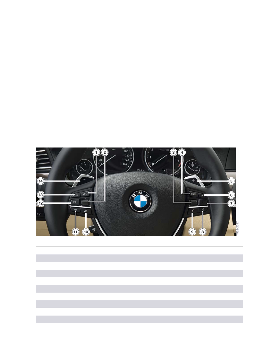
2.5.�Controls�on�the�steering�wheel
There�is�a�switch�block�in�the�steering�wheel�on�the�left�and�right.
The�operating�elements�for�cruise�control�with�braking�function�(Dynamic�Cruise�Control�DCC)�and�the
Active�Cruise�Control�ACC�are�located�on�the�left�side�of�the�steering�wheel.
The�controls�for�operation�of�the�radio�and�telephone�functions�are�on�the�right.
F10�Controls�on�the�steering�wheel
Index
Explanation
1
Reduce�distance�button�(only�with�option�5DF)
2
±�rocker�switch,�change�speed,�set�speed
3
Knurled�wheel,�select/set�radio�station�or�music�track
4
MODE�button,�switch�audio�sources
5
Shift�up�shift�paddle�(only�with�option�2TB)
6
+�rocker�switch,�increase�volume
7
-�rocker�switch,�reduce�volume
8
Voice�control�button
9
Telephone�button
F10�Displays,�Indicators�and�Controls
2.�System�Components
8
Index
Explanation
10
Increase�distance�button�(only�with�option�5DF)
11
Switch�on/off,�interrupt�ACC/DCC
12
Resume,�call�up�stored�speed�button
13
Speed�limit�button�or�the�“SET”�speed�button�in�the�US
14
Shift�down�shift�paddle�(only�with�option�2TB)
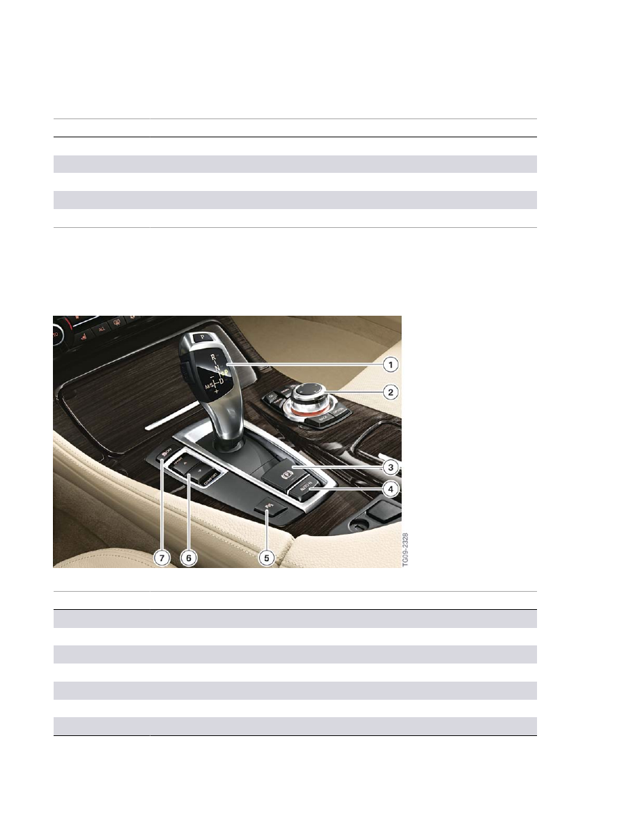
2.6.�Operating�controls�in�the�center�console
The�operating�elements�in�the�center�console�have�the�same�function�and�arrangement�as�those�in�the
F01.
F10�Operating�controls�in�the�center�console
Index
Explanation
1
Gear�selector�switch
2
Controller
3
Parking�brake
4
Automatic�Hold
5
Park�Distance�Control�or�parking�assistance
6
Handling�setting�switch
7
Dynamic�Stability�Control

F10�Displays,�Indicators�and�Controls
2.�System�Components
9
2.7.�Driver�assistance�systems�operating�unit
The�individual�assist�systems�can�be�activated�or�deactivated�via�the�assist�system�operating�unit.�It�is
located�next�to�the�steering�wheel�in�the�dashboard.
F10�Assist�system�operating�unit
Index
Explanation
1
Blind�Spot�Detection
2
Collision�warning�(adaptive�dynamic�brake�control�with�warning�function)
3
Lane�Departure�Warning
4
Night�Vision�with�person�recognition
5
Head‐Up�Display
For�more�information�on�the�assist�systems�refer�to�the�"F10�Assist�systems"�of�this�training�material.

Bayerische�Motorenwerke�Aktiengesellschaft
Händlerqualifizierung�und�Training
Röntgenstraße�7
85716�Unterschleißheim,�Germany
Document Outline
- Main Menu
- 01_F10 Introduction
- 02_F10 Powertrain
- 03_F10 Chassis Dynamics
- 04_F10 General Vehicle Electronics
- 05_F10 Driver Assistance Systems
- 06_F10 Displays, Indicators and Controls
- 07_F10 Entertainment and Communication
- 08_F10 Passive Safety Systems
Wyszukiwarka
Podobne podstrony:
06 1 F01 Displays Indicators and Controls
06a E70 Displays Indicators and Controls
15427 indicators and display devicesid 16461 pptx
Marijuana is one of the most discussed and controversial topics around the world
P4 explain how an individual?n exercise command and control
06 Memory Related Perils and Pitfalls
Power Converters And Control Renewable Energy Systems
Causes and control of filamentous growth in aerobic granular sludge sequencing batch reactors
What is command and control
06 x86 64 Procedures and Stacks
2009 6 NOV Small Animal Parasites Biology and Control
Active Sub Woofer and Controller
[0] Step Motor And Servo Motor Systems And Controls
Monitoring and Controlling the Project
foc im and control by sliding mode
Matlab Tutorial for Systems and Control Theory (MIT) (1999) WW
P4 explain how ben can exercise command and control
Handbook of Occupational Hazards and Controls for Staff in Central Processing
CSB 1065 1 Secondary Display No display indicator
więcej podobnych podstron