
SECTION : 9U
CRUISE CONTROL SYSTEM
CAUTION : Disconnect the negative battery cable before removing or installing any electrical unit or when a tool
or equipment could easily come in contact with exposed electrical terminals. Disconnecting this cable will help
prevent personal injury and damage to the vehicle. The ignition must also be in LOCK unless otherwise noted.
TABLE OF CONTENTS
SPECIFICATIONS
9U–1
. . . . . . . . . . . . . . . . . . . . . . . . . .
FASTENER TIGHTENING SPECIFICATIONS
9U–1
.
SCHEMATIC AND ROUTING DIAGRAMS
9U–2
. . . . .
CRUISE CONTROL SYSTEM (AUTOMATIC
TRANSAXLE) (1 OF 2)
9U–2
. . . . . . . . . . . . . . . . . . .
CRUISE CONTROL SYSTEM (AUTOMATIC
TRANSAXLE) (2 OF 2)
9U–3
. . . . . . . . . . . . . . . . . . .
CRUISE CONTROL SYSTEM (MANUAL
TRANSAXLE) (1 OF 2)
9U–4
. . . . . . . . . . . . . . . . . . .
CRUISE CONTROL SYSTEM (MANUAL
TRANSAXLE) (2 OF 2)
9U–5
. . . . . . . . . . . . . . . . . . .
DIAGNOSIS
9U–6
. . . . . . . . . . . . . . . . . . . . . . . . . . . . . . . .
CRUISE CONTROL DIAGNOSIS
9U–6
. . . . . . . . . . . .
MAINTENANCE AND REPAIR
9U–11
. . . . . . . . . . . . . .
ON–VEHICLE SERVICE
9U–11
. . . . . . . . . . . . . . . . . . . .
CRUISE CONTROL ACTUATOR
9U–11
. . . . . . . . . . .
ACTUATOR CONTROL CABLE
9U–15
. . . . . . . . . . . .
MAIN SWITCH
9U–17
. . . . . . . . . . . . . . . . . . . . . . . . . . .
GENERAL DESCRIPTION AND SYSTEM
OPERATION
9U–19
. . . . . . . . . . . . . . . . . . . . . . . . . . . . .
CRUISE CONTROL SYSTEM OPERATION
9U–19
.
CRUISE CONTROL ACTUATOR
9U–19
. . . . . . . . . . .
MAIN SWITCH
9U–19
. . . . . . . . . . . . . . . . . . . . . . . . . . .
LEVER SWITCH
9U–19
. . . . . . . . . . . . . . . . . . . . . . . . .
SPECIFICATIONS
FASTENER TIGHTENING SPECIFICATIONS
Application
N
S
m
Lb–Ft
Lb–In
Actuator Bolts
4
–
35
Actuator Bracket Nuts
18
13
–
9U – 2
I
CRUISE CONRTOL SYSTEM
DAEWOO V–121 BL4
SCHEMATIC AND ROUTING DIAGRAMS
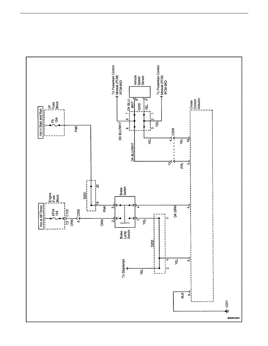
CRUISE CONTROL SYSTEM (AUTOMATIC TRANSAXLE)
(1 OF 2)
CRUISE CONRTOL SYSTEM 9U – 3
DAEWOO V–121 BL4
CRUISE CONTROL SYSTEM (AUTOMATIC TRANSAXLE)
(2 OF 2)
9U – 4
I
CRUISE CONRTOL SYSTEM
DAEWOO V–121 BL4
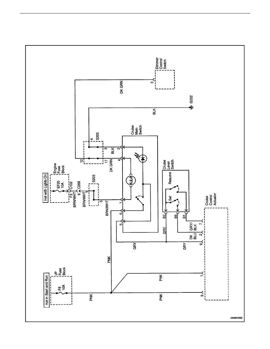
CRUISE CONTROL SYSTEM (MANUAL TRANSAXLE) (1
OF 2)

CRUISE CONRTOL SYSTEM 9U – 5
DAEWOO V–121 BL4
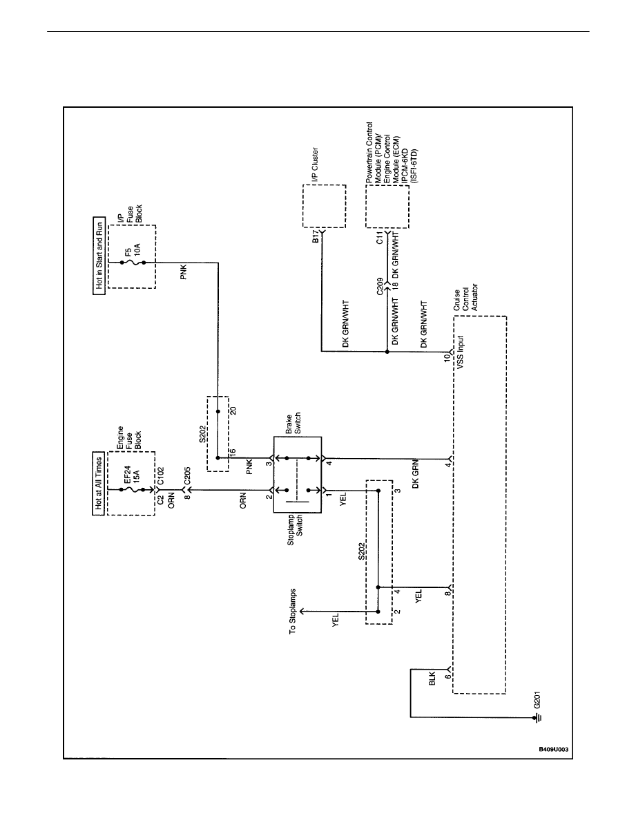
CRUISE CONTROL SYSTEM (MANUAL TRANSAXLE) (2
OF 2)

9U – 6
I
CRUISE CONRTOL SYSTEM
DAEWOO V–121 BL4
DIAGNOSIS
CRUISE CONTROL DIAGNOSIS
Test Description
The number(s) below refer to step(s) on the diagnostic
table.
5.
This test is performed because the electromagnetic
clutch in the cruise control actuator is grounded
through the brake lamps.
Cruise Control Does Not Operate
Step
Action
Value(s)
Yes
No
1
Visually inspect the cruise control system and verify
the following conditions:
S
The electrical connector is correctly attached to
the cruise control actuator.
S
The actuator and the bracket are not loose.
S
The cable is not bent or kinked.
S
The cable adjuster is correctly attached to its
bracket.
S
The cable and bushing are correctly attached
to the accelerator assembly.
S
The cable is properly adjusted.
Are all of the above conditions verified?
Go to Step 3
Go to Step 2
2
Make repairs to the components of the cruise control
system that were observed to be faulty in Step 1.
Is the repair complete?
System OK
3
1. Connect a scan tool to the data link connector
(DLC).
2. Check for engine control diagnostic trouble
codes (DTCs).
Is a vehicle speed sensor (VSS)DTCorDTC722 or
DTC723 present?
Go to Step 5
Go to Step 4
4
Diagnose and repair the cause of theDTCs.
Is the cruise control still inoperative?
Go to Step 5
System OK
5
Observe the brake lamps when the brakes are ap-
plied.
Do the brake lamps turn on when the brakes are ap-
plied and turn off when the brakes are not applied?
Go to Step 7
Go to Step 6
6
Repair the brake lamp system.
Does the cruise control operate after the brake lamp
system has been repaired?
System OK
Go to Step 7
7
Check fuses F5 andF8.
Is a fuse blown?
Go to Step 9
Go to Step 8
8
1. Check for a short circuit and repair it, if neces-
sary.
2. Replace any blown fuses.
Is the repair complete?
System OK
9
1. Turn the ignition ON.
2. Check the voltage at fuses F5 and F8.
Is the specified voltage available at fuses F5 andF8?
11–14 v
Go to Step 11
Go to Step 10
10
Repair the power supply to the fuse(s).
Is the repair complete?
System OK

CRUISE CONRTOL SYSTEM 9U – 7
DAEWOO V–121 BL4
Step
No
Yes
Value(s)
Action
11
1. Disconnect the electrical connector from the
cruise control actuator.
2. Turn the ignition ON.
3. Check the voltage at terminal H of the actuator
connector.
Is the voltage equal to the specified value?
11–14 v
Go to Step 13
Go to Step 12
12
Repair the open circuit between fuseF8 and the
cruise control actuatorconnector terminal 3.
Is the repair complete?
System OK
13
With the electrical connectorstill removed fromthe
cruise control actuator, use an ohmmeter tomeasure
the resistance between connector terminal 6 and
ground.
Does the ohmmeter indicate the specified value?
[
0
W
Go to Step 15
Go to Step 14
14
Repair the open circuit between ground and terminal
6 of the actuatorconnector.
Is the repair complete?
System OK
15
With the electrical connectorstill disconnected from
the cruise control actuator, use an ohmmeter to
measure the resistance between connector terminal
8 and ground.
Does the ohmmeter indicate the specified value?
[
0
W
Go to Step 17
Go to Step 16
16
Repair the open circuit between the actuator con-
nector terminal 8 and the instrument splice pack
S202.
Is the repair complete?
System OK
17
1. Turn the ignition ON.
2. With the electrical connector still disconnected
from the cruise control actuator, use a voltme-
ter to check the voltage at terminal 4 of the
connector.
Is the voltage equal to the specified value?
11–14 v
Go to Step 19
Go to Step 18
18
Repair the open circuit between fuseF5 and terminal
4 of the cruise control actuatorconnector.
Is the repair complete?
System OK
19
1. Turn the ignition ON.
2. With the electrical connector still disconnected
from the cruise control actuator, use a voltme-
ter to check the voltage at terminal 1 of the
connector.
Is the voltage equal to the specified value?
11–14 v
Go to Step 21
Go to Step 20
20
Repair the open circuit between fuseF8 and terminal
1 of the cruise control actuator.
Is the repair complete?
System OK
21
1. Turn the ignition ON.
2. Make sure that the cruise main switch is OFF.
3. With the electrical connector still disconnected
from the cruise control actuator, use a voltme-
ter to check the voltage at terminal 9 of the ac-
tuator connector.
Is the voltage equal to the specified value?
[
0 v
Go to Step 23
Go to Step 22

9U – 8
I
CRUISE CONRTOL SYSTEM
DAEWOO V–121 BL4
Step
No
Yes
Value(s)
Action
22
Repair the short to voltage between the cruisemain
switch and the cruise control actuatorconnector ter-
minal 9.
Is the repair complete?
System OK
23
1. Turn the ignition ON.
2. Make sure that the cruise main switch is ON.
3. With the electrical connector still disconnected
from the cruise control actuator, use a voltme-
ter to check the voltage at terminal 9 of the
connector.
Is the voltage equal to the specified value?
11–14 v
Go to Step 29
Go to Step 24
24
1. Remove the cruise control main switch for test-
ing, but leave the electrical connector attached.
2. Turn the ignition ON.
3. Check the voltage at the PNK wire at the cruise
main switch.
Is the voltage equal to the specified value?
11–14 v
Go to Step 26
Go to Step 25
25
Repair the open circuit in thePNK wire between fuse
F8 and the cruise controlmain switch.
Is the repair complete?
System OK
26
1. With the cruise control main switch removed
for testing, turn the ignition ON.
2. Turn the cruise control main switch ON.
3. Check the voltage at the GRY wire at the
cruise main switch.
Is the voltage equal to the specified value?
11–14 v
Go to Step 27
Go to Step 25
27
Replace the cruise control main switch.
Is the repair complete?
System OK
28
Repair the open circuit between the cruise control
main switch connector terminal 5 and the cruise con-
trol actuatorconnector terminal 9.
Is the repair complete?
System OK
29
1. Turn the ignition ON.
2. Turn the cruise control main switch ON.
3. With the electrical connector still disconnected
from the cruise control actuator, check the volt-
age at terminals 7 and 2 of the connector.
Is the voltage equal to the specified value?
[
0 v
Go to Step 33
Go to Step 30
30
1. Disconnect the 6–pin connector at the cruise
control lever switch.
2. Turn the ignition ON.
3. Turn the cruise control main switch ON.
4. With the electrical connector still disconnected
from the cruise control actuator, check the volt-
age at terminals 7 and 2 of the cruise control
actuator.
Is the voltage equal to the specified value?
0 v
Go to Step 31
Go to Step 32
31
Replace the cruise control lever switch.
Is the repair complete?
System OK
32
Repair the short to voltage between the cruise con-
trol lever switch and the cruise control actuator.
Is the repair complete?
System OK

CRUISE CONRTOL SYSTEM 9U – 9
DAEWOO V–121 BL4
Step
No
Yes
Value(s)
Action
33
1. Turn the ignition ON.
2. Turn the cruise control main switch ON.
3. Select SET on the cruise control lever switch.
4. While holding the lever switch in the SET posi-
tion, check the voltage at terminal 2 of the con-
nector for the cruise control actuator.
Does the voltmeter indicate the specified value?
11–14 v
Go to Step 39
Go to Step 34
34
1. Disconnnect the 6–pin connector from the lever
switch.
2. Turn the ignition ON.
3. Turn the cruise control main switch ON.
4. Check the voltage at terminal 3 of the wiring
harness side of the 6–pin lever switch connec-
tor.
Is the voltage equal to the specified value?
11–14 v
Go to Step 36
Go to Step 35
35
Repair the open circuit between the cruise control
main switch and the cruise control lever switch.
Is the repair complete?
System OK
36
1. Disconnect the 6–pin connector from the lever
switch.
2. Connect an ohmmeter between terminals 3
and 8 at the switch side of the 6–pin connector.
3. Observe the ohmmeter when moving the lever
switch to the SET position.
Does the ohmmeter indicate the specified value?
[
0
W
Go to Step 38
Go to Step 37
37
Replace the lever switch.
Is the repair complete?
System OK
38
Repair the open circuit between the leverswitch con-
nector terminalB6 and the cruise control actuator
connector terminal 2.
Is the repair complete?
System OK
39
1. Turn the ignition ON.
2. Turn the cruise control main switch ON.
3. Select RESUME on the cruise control lever
switch.
4. While holding the lever switch in the RESUME
position, check the voltage at terminal 7 of the
connector for the cruise control actuator.
Does the voltmeter indicate the specified value?
11–14 v
Go to Step 42
Go to Step 40
40
Use the ohmmeter to check foran open circuit be-
tween terminalB1 of thewiring harness at the lever
switch and terminal 7 of the actuatorconnector.
Does the ohmmeter indicate the specified value?
[
0
W
Go to Step 37
Go to Step 41
41
Repair the open circuit between terminalB1 of the
leverswitch connectorand terminal 7 of the cruise
control actuatorconnector.
Is the repair complete?
System OK

9U – 10
I
CRUISE CONRTOL SYSTEM
DAEWOO V–121 BL4
Step
No
Yes
Value(s)
Action
42
1. Turn the ignition OFF.
2. If the vehicle has amanual transaxle, discon-
nect the VSS electrical connector.
3. If the vehicle has an automatic transaxle, dis-
connect the electrical connector from the trans-
axle output shaft sensor.
S
If the vehicle has a manual transaxle, use an
ohmmeter to check continuity between the DK
GRN/WHT wire at the VSS and terminal 10 of
the cruise control actuator connector.
S
If the vehicle has an automatic transaxle,
check the continuity of the following wires:
– The YEL wire between cruise control ac-
tuator connector terminal 10 and VSS con-
nector terminal A.
– The PPL wire between cruise control ac-
tuator connector terminal 5 and VSS con-
nector terminal B.
Does the ohmmeter indicate the specified value
when checking the wire(s) between the cruise con-
trol module and the VSS, for vehicles with amanual
transaxle, or the output shaft sensor, for vehicles
with an automatic transaxle?
[
0
W
Go to Step 44
Go to Step 43
43
Repair the open circuit between the cruise control
actuatorconnector terminal 10 and theVSS, for ve-
hicles with amanual transaxle, or the output shaft
sensor forvehicles with an automatic transaxle.
Is the repair complete?
System OK
44
Replace the cruise control actuator.
Is the repair complete?
System OK
CRUISE CONRTOL SYSTEM 9U – 11
DAEWOO V–121 BL4
MAINTENANCE AND REPAIR
ON–VEHICLE SERVICE
CRUISE CONTROL ACTUATOR
Removal Procedure
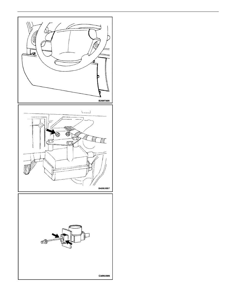
1. Carefully pull the knee bolster trim panel until it is
loose from its retaining clips.
2. Remove the knee bolster. Refer to Section 9G, In-
terior Trim.
3. Remove the actuator bracket with the actuator still
attached.
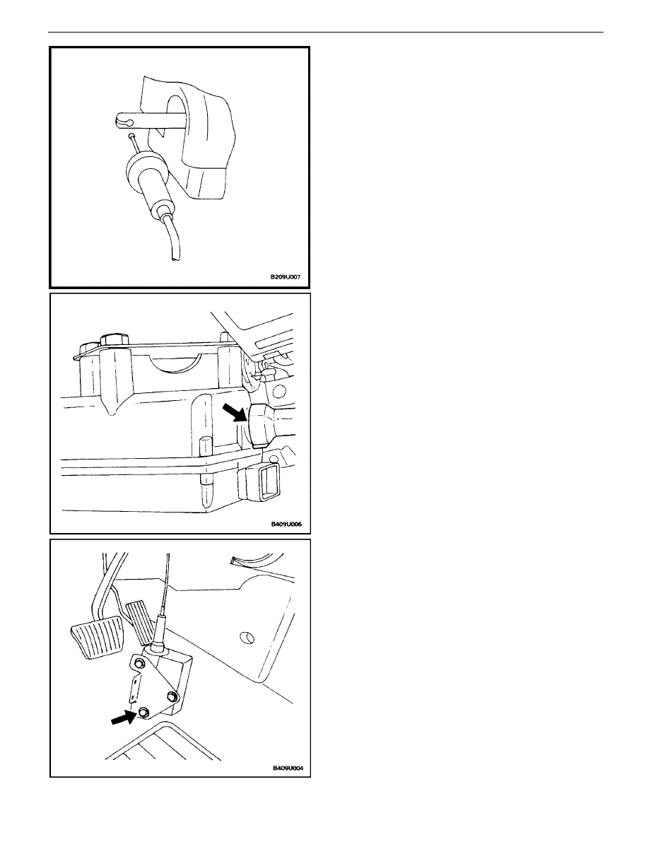
4. Press the tabs on the cable adjuster, and remove
the cable and the adjuster from the adjuster brack-
et.

9U – 12
I
CRUISE CONRTOL SYSTEM
DAEWOO V–121 BL4
5. Tilt the cable housing to expose one of the slots in
the actuator, and insert the tip of a flathead screw-
driver into one of the slots.
6. Tilt the cable housing toward the screwdriver to re-
lease the cable housing retainers.
7. Remove the cable ball from the actuator rod.
CRUISE CONRTOL SYSTEM 9U – 13
DAEWOO V–121 BL4
Installation Procedure
1. Insert the cable ball into the actuator rod.
2. Align the cable housing and push the cable housing
onto the actuator until it is locked in place by the
retainers.
3. If a new actuator is being installed, attach it to the
mounting bracket.
Tighten
Tighten the actuator bolts to 4 N
S
m (35 lb–in).
9U – 14
I
CRUISE CONRTOL SYSTEM
DAEWOO V–121 BL4
4. Install the mounting bracket.
Tighten
Tighten the actuator bracket nuts to 18 N
S
m (13 lb–ft).
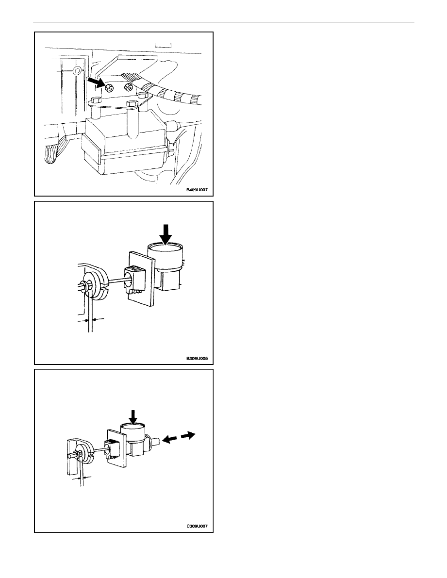
5. If the adjuster spring is not fully compressed, press
the cable release button and slide the cable into the
adjuster until the spring is fully compressed.
Notice : When the adjuster button is pressed, do not allow
the adjuster spring to expand to a length of more than 2 cm
(3/4 inch) or the adjuster rack will come out of the adjuster,
and will have to be re–inserted. To keep the adjuster in one
piece during adjustment, hold the cable when the adjuster
button is pressed.
6. Insert the cable adjuster into the adjuster bracket.
7. Press the cable release button and adjust the cable
to achieve a gap of 0.5 mm (0.02 inches) between
the bushing and the nipple of the cable ball.
8. Install the knee bolster. Refer to Section 9G, Interi-
or Trim.
9. Install the knee bolster trim panel.
CRUISE CONRTOL SYSTEM 9U – 15
DAEWOO V–121 BL4
ACTUATOR CONTROL CABLE
Removal Procedure
1. Press the release button on the cable adjuster, and
push the cable toward the adjuster until the adjuster
spring is compressed.
Notice : When the adjuster button is pressed, do not allow
the adjuster spring to expand to a length of more than 2 cm
(3/4 inch) or the adjuster rack will come out of the adjuster,
and will have to be re–inserted. To keep the adjuster in one
piece during adjustment, hold the cable when the adjuster
button is pressed.
2. Press the retaining tabs of the cable adjuster, and
remove the adjuster from the mounting bracket.
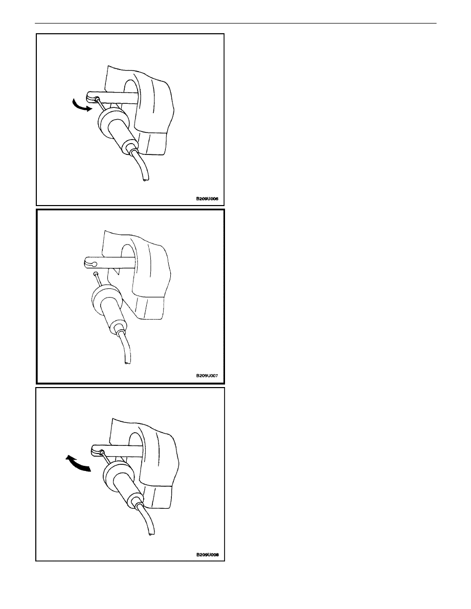
3. Tilt the cable housing and insert a flathead screw-
driver into one of the slots in the actuator.
4. Tilt the cable housing toward the screwdriver, so
that the cable housing retainers will release.
9U – 16
I
CRUISE CONRTOL SYSTEM
DAEWOO V–121 BL4
5. Slide the sleeve and the cable out of the actuator
and rotate the cable so it can be removed from the
slot in the actuator rod.
6. Remove the cable ball from the actuator rod.
Installation Procedure
1. Insert the ball nipple of the cable assembly into the
slot in the actuator rod, and then rotate the cable 90
degrees.
CRUISE CONRTOL SYSTEM 9U – 17
DAEWOO V–121 BL4
2. Align the cable housing and push the cable housing
onto the actuator until it is locked in place by the
retainers.
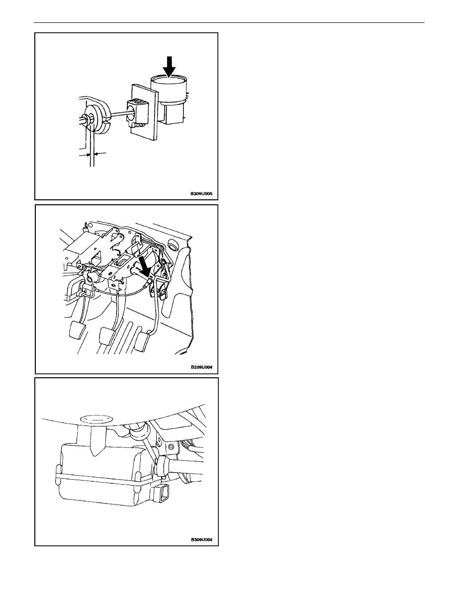
3. Insert the cable adjuster into the bracket of the ped-
al mount assembly.
4. If the adjuster spring is not fully compressed, press
the cable release button and slide the cable into the
adjuster until the spring is fully compressed.
5. Install the cable bushing into the pedal assembly.
6. Press the cable release button and adjust the cable
to achieve a gap of 0.5 mm (0.02 inches) between
the bushing and the nipple of the ball.
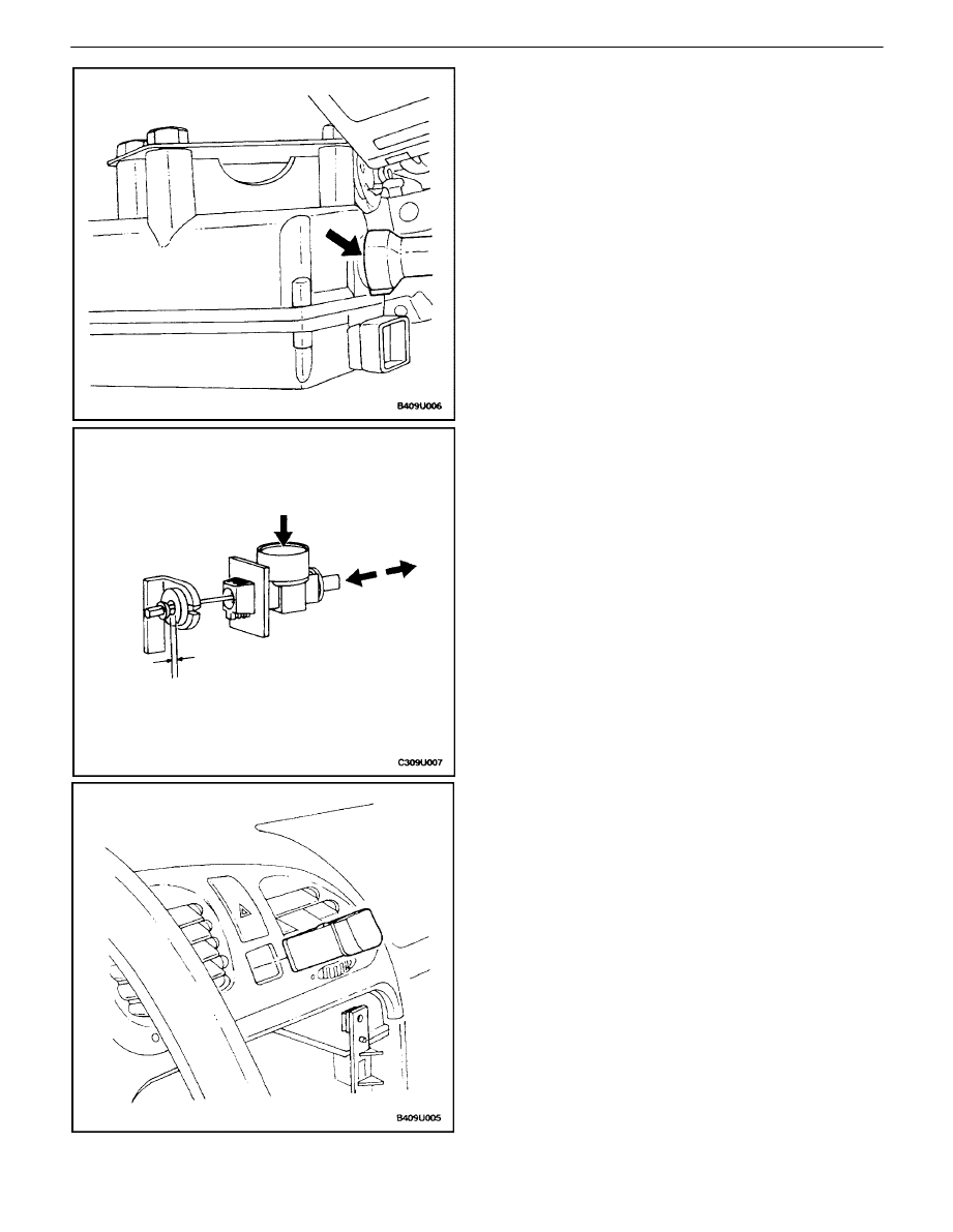
MAIN SWITCH
Removal Procedure
1. Remove the radio, taking care not to scratch the
instrument panel or trim with the corners of the ra-
dio case. Refer to Section 9F, Audio Systems.
2. Reach through the radio opening in the instrument
panel and wiggle the cruise control main switch to
loosen it.
3. Push the cruise control main switch out of the in-
strument panel.
4. Disconnect the electrical connector from the cruise
control main switch.
9U – 18
I
CRUISE CONRTOL SYSTEM
DAEWOO V–121 BL4
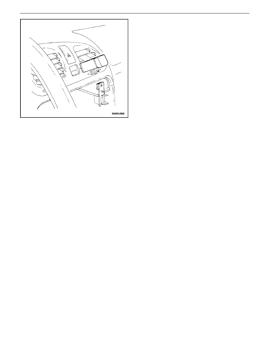
Installation
1. Connect the electrical connector to the cruise con-
trol main switch.
2. Push the cruise control main switch into the instru-
ment panel until it is locked in place by its retainers.
3. Reinstall the radio, taking care not to scratch the
instrument panel or trim when installing the radio
case. Refer to Section 9F, Audio Systems.

CRUISE CONRTOL SYSTEM 9U – 19
DAEWOO V–121 BL4
GENERAL DESCRIPTION
AND SYSTEM OPERATION
CRUISE CONTROL SYSTEM
OPERATION
The cruise control system automatically maintains a ve-
hicle speed set by the driver. When the cruise control sys-
tem is activated, speed is maintained or increased by
means of an electronically controlled cable attached to the
accelerator assembly. If the vehicle must be slowed to
maintain the speed set by the driver, the cruise control sys-
tem allows the throttle return spring to close the throttle.
If driving conditions require sudden acceleration after the
cruise control has been set, speed can be increased in the
normal manner by manually pressing the accelerator. The
cruise control is disengaged if the brakes (or the clutch,
with a manual transaxle) are applied.
The minimum speed for setting the cruise control is 38.6
km/h (24 mph). When cruise control is operating, the
CRUISE indicator lamp is turned ON in the instrument
cluster.
The cruise control system is capable of monitoring internal
software and hardware faults as well as external faults in
the connectors and the wire harness. If a fault is detected,
cruise control is stopped immediately, and the program
logic and hardware logic both prevent the cruise control
from opening the throttle.
The cruise control will function in temperatures ranging
from –40
°
C (–40
°
F) to 85
°
C (185
°
F). Maximum tempera-
ture could cause the regulation properties to be out of tol-
erance, but the safety shutdown is still operational under
maximum temperature conditions. If high temperature in-
terferes with the cruise control operation, the actuator
electromagnetic clutch will open, and the throttle return
spring will close the throttle unless the accelerator pedal
is pressed.
CRUISE CONTROL ACTUATOR
The cruise control actuator is a single–component sys-
tem. The electronic controls are combined in one housing
with the mechanical components. The actuator is
mounted in the passenger compartment..
The mechanical components of the cruise control actuator
are listed below:
S
Permanent field DC motor.
S
Single stage belt transfer gearing.
S
Spindle
drive.
S
Electromagnetic
clutch.
S
Clutch plate with cable attachment.
S
End
switches.
S
Plastic housing with noise reduction cover.
S
Damping unit for clutch plate slap.
The electronics of the cruise control system include the
following items:
S
A microprocessor which controls speed regulation
and monitors input signals.
S
A clutch activation circuit which energizes the
clutch magnet in order to couple the DC motor to
the control cable.
S
A driver circuit which activates the DC motor in a
clockwise or counterclockwise direction.
S
A control unit for lamp activation.
The parts of the cruise control actuator are not service-
able. The entire actuator must be replaced if there is an
electronic or mechanical defect in one of the systems.
MAIN SWITCH
The cruise control main switch is on the center of the in-
strument panel.
Cruise control can only be set with the lever switch when
the main switch is ON.
The main switch has an indicator which turns ON when the
main switch is pressed. If the switch is pressed again, the
indicator and the switch turn OFF.
The main switch also is connected to the instrument illumi-
nation system, so the dimmer switch controls switch illumi-
nation when the headlamps or parking lamps are ON.
LEVER SWITCH
After the main switch is turned ON and the neutral position
of the lever switch is detected by the cruise control actua-
tor, the following operations can be performed by using the
cruise control lever switch:
Set – If the cruise control is ON and the minimum speed
is 38.6 km/h (24 mph) but not more than 155 km/h (96
mph), the target speed can be set by selecting the SET
function for 10 to 300 milliseconds. If SET is selected for
more than 300 milliseconds, the cruise will be activated in
the COAST function. If the accelerator is pressed by the
driver after the cruise control has been set, the previous
target speed will be maintained when the accelerator is re-
leased. If the accelerator is pressed by the driver until the
actual speed is more than 35 km/h (22 mph) over the tar-
get speed, or until the vehicle exceeds 160 km/h (99 mph),
the cruise control will disengage.
Coast – If a target speed has been set and COAST is se-
lected for at least 300 milliseconds, the throttle is allowed
to return to idle and the vehicle will coast. When the
COAST switch is released, the current speed will be main-
tained as the new target speed. If the vehicle speed drops

9U – 20
I
CRUISE CONRTOL SYSTEM
DAEWOO V–121 BL4
below 32.2 km/h (20 mph) while coasting, the cruise con-
trol will be disengaged. If the switch is released between
32.2 km/h (20 mph) and 38.6 km/h (24 mph), the minimum
target speed of 38.6 km/h (24 mph) will be used.
Resume – If the cruise control is ON and the system is dis-
engaged by using the brake or the clutch, exceeding the
maximum speed, failing to maintain the minimum speed,
or exceeding the target speed by more than 35 km/h (22
mph), the last memorized speed can be reset by selecting
RESUME, if the time since disengagement is not greater
than 5 seconds. The RESUME function is selected by
switching to RESUME for 10 to 300 milliseconds. If the ac-
tual speed is below the target speed when RESUME is se-
lected, the vehicle will be accelerated at 3.4 km/h per sec-
ond (2.1 mph/second) until the vehicle is within 10 km/h (6
mph) of the target speed, and then acceleration will be re-
duced in order to achieve a smooth transition from accel-
eration to cruising. If the actual speed is above the target
speed when RESUME is selected, the throttle will be al-
lowed to return to idle until the target speed is achieved.
RESUME can be canceled by selecting SET. In that case,
the current speed will be maintained as the new target
speed.
Accelerate – If cruise control is ON, and the ACCEL func-
tion is selected for more than 300 milliseconds, the vehicle
will accelerate. The acceleration is maintained at the rate
of 3.4 km/h per second (2.1 mph/second) as long as ve-
hicle performance is sufficient; otherwise full throttle is ap-
plied. When the switch is released, the current speed will
be stored and used as the new target speed. The ACCEL
function cannot be used for acceleration above 155 km/h
(96 mph). If 155 km/h (96 mph) is attained, acceleration
will stop and 155 km/h (96 mph) will be set as the new tar-
get speed.
Tap–Up – If the cruise control has been set, and RESUME
is selected again for more than 10 milliseconds but less
than 300 milliseconds, the target speed will be increased
by 2 km/h (1.2 mph) each time the RESUME function is
selected (or tapped). If the driver has used the accelerator
to increase speed more than 8 km/h over the current target
speed, a tap–up signal will be interpreted as a normal SET
signal. The cruise control will not accept a tap–up target
speed above 155 km/h (96 mph). If the actual speed has
fallen 16.1 km/h (10 mph) below the target speed, tap–up
signals are not accepted.
Tap–Down – If the cruise control is already set and SET
is selected for between 10 and 300 milliseconds, the target
speed will be decreased by 2 km/h (1.2 mph) each time
SET is selected (or tapped). Tap–down signals will not be
accepted for a target speed below 38.6 km/h (24 mph). If
the vehicle speed has increased to 8 km/h (5 mph) over
the target speed, the cruise control system will interpret a
tap–down signal as a SET.
If the cruise control is turned OFF with the main switch, all
cruise control functions are stopped, the actuator cable is
driven toward idle, and the electromagnetic clutch for the
cable actuator is opened. The cable actuator clutch is not
opened immediately in order to accomplish a smooth tran-
sition in vehicle speed. If the cruise control is OFF for more
than 5 seconds, the memorized target speed is erased.
Wyszukiwarka
Podobne podstrony:
Cruise Control I4
82 Cruise Control
diagnostics Cruise Control
Cruise Control V6
2 5TD cruise control
32 Audi A6 Cruise control system petrol engines
Cruise Control Circuit
BMW E38 schematic Cruise control
04 6 F01 Cruise Control Systems
cruise control system
ENGINE CONTROLS SECTION 1F 14
diagnostics Cruise Control
ENGINE COOLING SECTION 1D 19
Opcom Cruise Control
Toyota Avensis Y Corrolla esquema Cruise Control On Vehicle Inspection
BODY REAR END SECTION 9S 19
ENGINE CONTROLS SECTION 1F 377 403
więcej podobnych podstron