
SECTION : 9S
BODY REAR END
CAUTION : Disconnect the negative battery cable before removing or installing any electrical unit or when a tool
or equipment could easily come in contact with exposed electrical terminals. Disconnecting this cable will help
prevent personal injury and damage to the vehicle. The ignition must also be in LOCK unless otherwise noted.
TABLE OF CONTENTS
SPECIFICATIONS
9S–1
. . . . . . . . . . . . . . . . . . . . . . . . . .
FASTENER TIGHTENING SPECIFICATIONS
9S–1
.
MAINTENANCE AND REPAIR
9S–3
. . . . . . . . . . . . . . .
ON–VEHICLE SERVICE
9S–3
. . . . . . . . . . . . . . . . . . . . .
FUEL FILLER DOOR
9S–3
. . . . . . . . . . . . . . . . . . . . . .
REAR DECK LID (NOTCHBACK)
9S–3
. . . . . . . . . . . .
REAR DECK LID SPRINGS (NOTCHBACK)
9S–5
. .
LUGGAGE COMPARTMENT LOCK CYLINDER 9S–
6
LUGGAGE COMPARTMENT LOCK STRIKER
(NOTCHBACK)
9S–7
. . . . . . . . . . . . . . . . . . . . . . . . . .
LUGGAGE COMPARTMENT LOCK (NOTCHBACK
AND HATCHBACK)
9S–7
. . . . . . . . . . . . . . . . . . . . . .
WEATHERSTRIP
9S–9
. . . . . . . . . . . . . . . . . . . . . . . . . .
HATCHBACK DOOR
9S–9
. . . . . . . . . . . . . . . . . . . . . . .
GAS SUPPORT ASSEMBLIES (HATCHBACK) 9S–10
LUGGAGE COMPARTMENT LOCK STRIKER
(HATCHBACK)
9S–11
. . . . . . . . . . . . . . . . . . . . . . . . .
REAR SPOILER (HATCHBACK)
9S–11
. . . . . . . . . . . .
TAILGATE (WAGON)
9S–12
. . . . . . . . . . . . . . . . . . . . .
GAS SUPPORT ASSEMBLIES (WAGON)
9S–13
. . .
LUGGAGE COMPARTMENT LOCK STRIKER
(WAGON)
9S–14
. . . . . . . . . . . . . . . . . . . . . . . . . . . . . .
REAR DECK LID/HATCHBACK DOOR REMOTE
CABLE AND HANDLE (NOTCHBACK)
9S–15
. . . .
FUEL FILLER DOOR REMOTE CABLE AND
HANDLE
9S–16
. . . . . . . . . . . . . . . . . . . . . . . . . . . . . . .
GENERAL DESCRIPTION AND SYSTEM
OPERATION
9S–19
. . . . . . . . . . . . . . . . . . . . . . . . . . . . .
FUEL FILLER DOOR
9S–19
. . . . . . . . . . . . . . . . . . . . .
REAR DECK LID (NOTCHBACK)
9S–19
. . . . . . . . . . .
HATCHBACK DOOR
9S–19
. . . . . . . . . . . . . . . . . . . . . .
TAILGATE (WAGON)
9S–19
. . . . . . . . . . . . . . . . . . . . .
SPECIFICATIONS
FASTENER TIGHTENING SPECIFICATIONS
Application
N
S
m
Lb–Ft
Lb–In
Fuel Filler Door Screws
4
–
35
Fuel Filler Door/Remote
Cable Handle Screws
8
–
71
Gas Support Assembly
Bolts
8
–
71
Gas Support Assembly
Studs
20
15
–
Hatchback Door Lock Strik-
er Screws
8
–
71
Hatchback Hinge Bolts
20
15
–
Lower B–Pillar Seat Belt
Anchor Bolt
35
26
–
Luggage Compartment
Lock Cylinder Nuts
4
–
35

9S – 2
I
BODY REAR END
DAEWOO V–121 BL4
Application
Lb–In
Lb–Ft
N
S
m
Luggage Compartment
Lock Screws
6
–
53
Luggage Compartment
Lock Striker Bolts
8
–
71
Rear Deck Lid Bolts
10
–
89
Rear Spoiler Nuts
4
–
35
Remote Cable Handle
Screws
8
–
71
Tailgate Hinge Bolts
20
15
–
Tailgate Lock Striker Bolts
10
–
89
BODY REAR END 9S – 3
DAEWOO V–121 BL4
MAINTENANCE AND REPAIR
ON–VEHICLE SERVICE
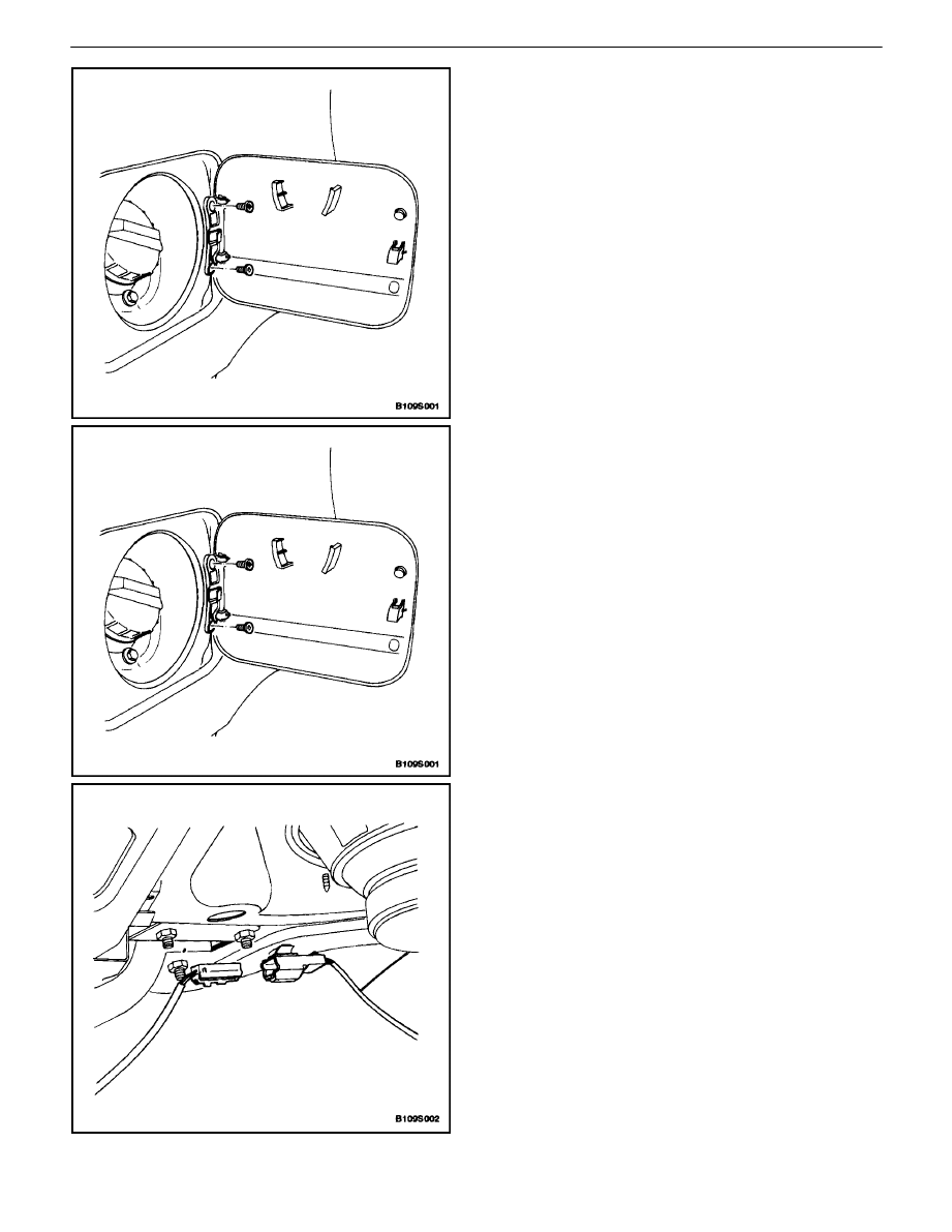
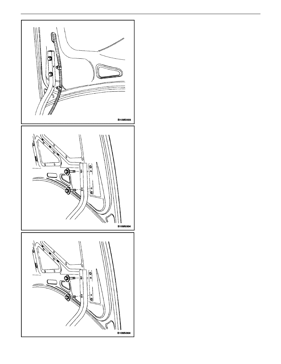
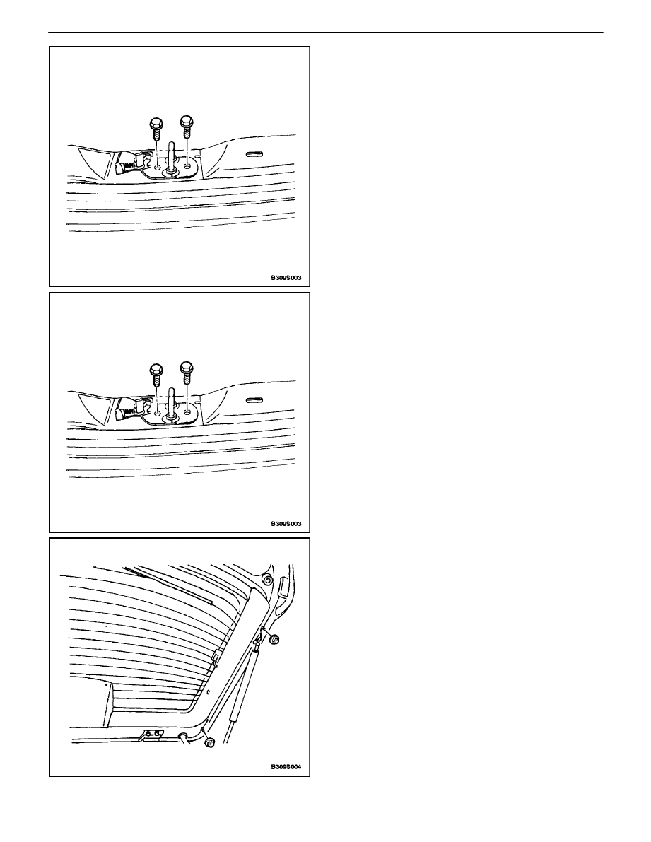
FUEL FILLER DOOR
Removal Procedure
1. Remove the screws and the fuel filler door.
Installation Procedure
Notice : Dissimilar metals in direct contact with each other
may corrode rapidly. Make sure to use the correct fasten-
ers to prevent premature corrosion.
1. Install the fuel filler door with the screws.
Tighten
Tighten the fuel filler door screws to 4 N
S
m (35 lb–in).
REAR DECK LID (NOTCHBACK)
Removal Procedure
1. Disconnect the negative battery cable.
2. Disconnect the electrical connector.
9S – 4
I
BODY REAR END
DAEWOO V–121 BL4
3. Remove the electrical harness from the rear deck
lid hinge arm.
4. Remove the bolts and the rear deck lid.
Installation Procedure
Notice : Dissimilar metals in direct contact with each other
may corrode rapidly. Make sure to use the correct fasten-
ers to prevent premature corrosion.
1. Install the rear deck lid with the bolts.
Tighten
Tighten the rear deck lid bolts to 10 N
S
m (89 lb–in).
BODY REAR END 9S – 5
DAEWOO V–121 BL4
2. Install the electrical harness to the rear deck lid
hinge arm.
3. Connect the electrical connector.
4. Connect the negative battery cable.
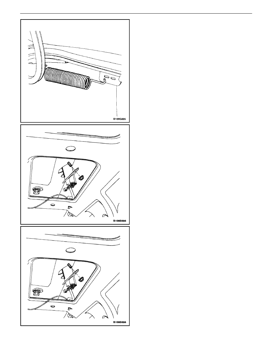
REAR DECK LID SPRINGS
(NOTCHBACK)
Removal Procedure
1. Raise and support the deck lid in the open position.
2. Pull the spring out of the rear mount.
3. Remove the spring from the hinge.
9S – 6
I
BODY REAR END
DAEWOO V–121 BL4
Installation Procedure
1. Install the spring into the hinge mount.
2. Extend the spring to mount it in the rear mounting
hole.
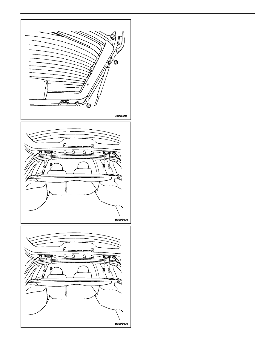
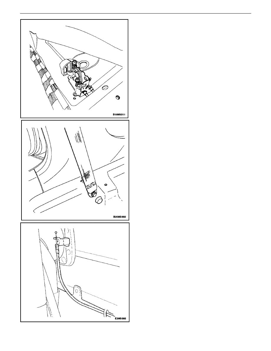
LUGGAGE COMPARTMENT LOCK
CYLINDER
(Notchback Shown, Hatchback and
Wagon Similar)
Removal Procedure
1. Remove the lower garnish molding (hatchback and
wagon only).
2. Remove the nuts that secure the lock cylinder.
3. Disconnect the lock rod.
4. Remove the luggage compartment lock cylinder.
Installation Procedure
1. Install the luggage compartment lock cylinder.
2. Connect the lock rod.
Notice : Dissimilar metals in direct contact with each other
may corrode rapidly. Make sure to use the correct fasten-
ers to prevent premature corrosion.
3. Secure the luggage compartment lock cylinder with
the nuts.
Tighten
Tighten the luggage compartment lock cylinder nuts
to 4 N
S
m (35 lb–in).
4. Install the lower garnish molding (hatchback and
wagon only).
BODY REAR END 9S – 7
DAEWOO V–121 BL4
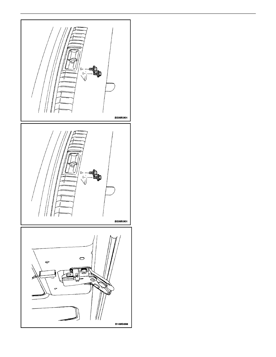
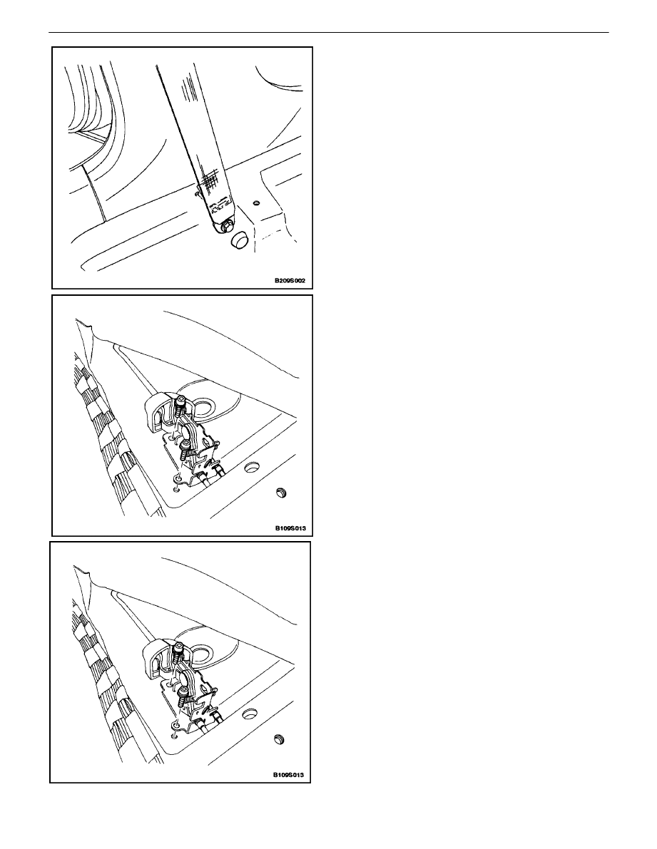
LUGGAGE COMPARTMENT LOCK
STRIKER (NOTCHBACK)
Removal Procedure
1. Open the luggage compartment.
2. Remove the bolts securing the lock striker.
3. Pull the lock striker out.
4. Disconnect the lock release cable from the lock
striker.
Installation Procedure
1. Connect the lock release cable.
Notice : Dissimilar metals in direct contact with each other
may corrode rapidly. Make sure to use the correct fasten-
ers to prevent premature corrosion.
2. Install the lock striker with the bolts.
Tighten
Tighten the luggage compartment lock striker bolts to
8 N
S
m (71 lb–in).
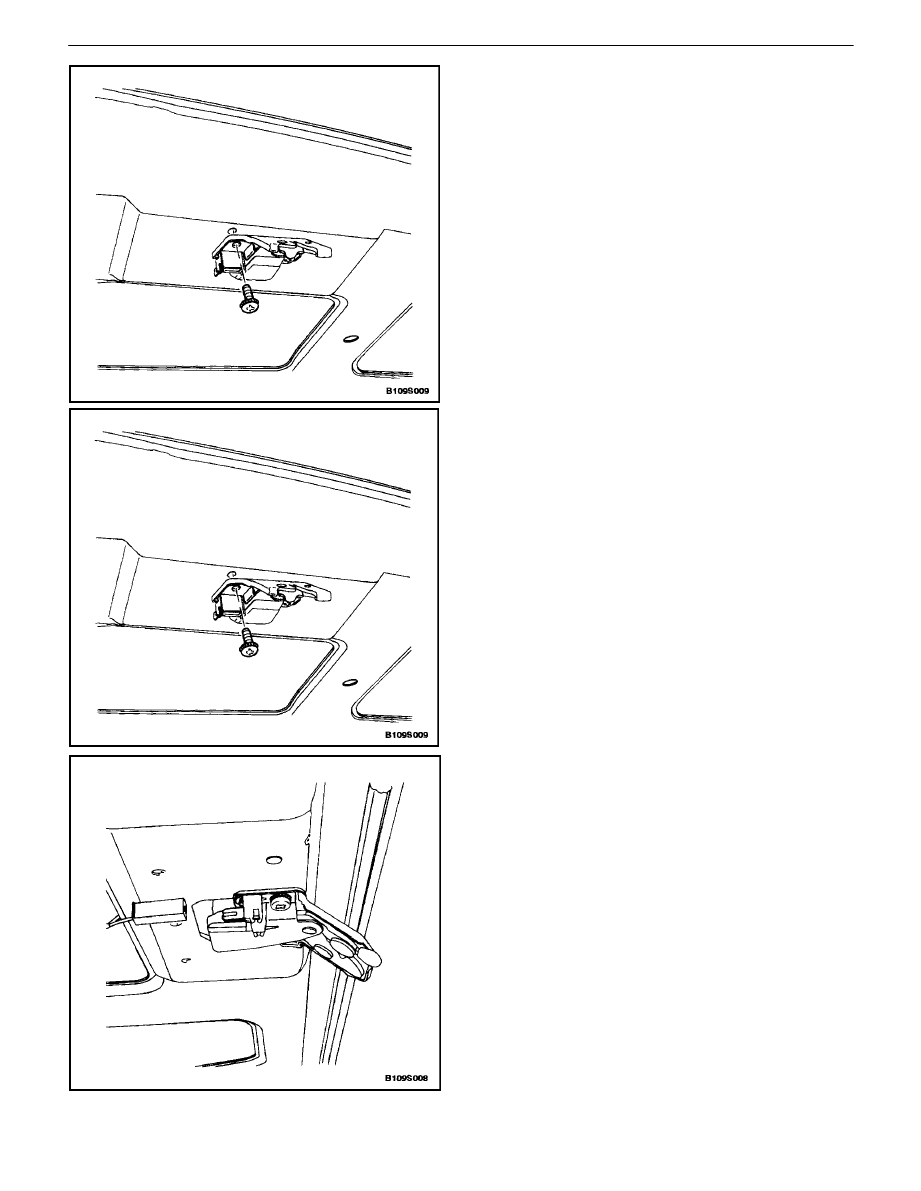
LUGGAGE COMPARTMENT LOCK
(NOTCHBACK AND HATCHBACK)
(Notchback Shown, Hatchback
Similar)
Removal Procedure
1. Disconnect the negative battery cable.
2. Remove the lock trim cover (hatchback only).
3. Disconnect the electrical connector.
9S – 8
I
BODY REAR END
DAEWOO V–121 BL4
4. Remove the screws and the luggage compartment
lock.
5. Disconnect the lock rod.
Installation Procedure
1. Connect the lock rod.
Notice : Dissimilar metals in direct contact with each other
may corrode rapidly. Make sure to use the correct fasten-
ers to prevent premature corrosion.
2. Install the luggage compartment lock with the
screws.
Tighten
Tighten the luggage compartment lock screws to 6
N
S
m (53 lb–in).
3. Connect the electrical connector.
4. Install the lock trim cover (hatchback only).
5. Connect the negative battery cable.
BODY REAR END 9S – 9
DAEWOO V–121 BL4
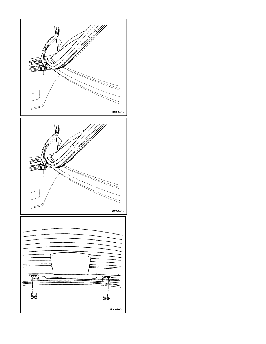
WEATHERSTRIP
(Notchback Shown, Hatchback
Similar)
Removal Procedure
1. Open the luggage compartment lid.
2. Remove the weatherstrip from around the gutter.
Installation Procedure
1. Install the weatherstrip onto the gutter flange.
2. Inspect the weatherstrip. Make sure that the clinch
is completely seated onto the flange.
3. Using a water hose without a nozzle, test the rear
deck lid to make sure that no leaks are present.
S
If there are no leaks present, the weatherstrip
does not need to be held in place. No further
repair is required.
S
If leaks are present, continue with the remainder
of the installation procedure.
4. Remove the weatherstrip.
5. Install the new weatherstrip onto the gutter flange.
HATCHBACK DOOR
Removal Procedure
1. Open and suitably support the hatchback door.
2. Disconnect the hatchback door grommets, electri-
cal connectors, and washer hose.
3. Remove the gas support assemblies from the
hatchback door. Refer to”Gas Support Assemblies
(Hatchback)” in this section.
4. With the aid of another technician, remove the bolts
and the hatchback door from the hinges.
9S – 10
I
BODY REAR END
DAEWOO V–121 BL4
Installation Procedure
1. With the aid of another technician, install the hatch-
back door to the hinges with the bolts.
Tighten
Tighten the hatchback hinge bolts to 20 N
S
m (15 lbft).
2. Install the gas support assemblies to the hatchback
door. Refer to”Gas Support Assemblies (Hatch-
back)” in this section.
3. Connect the hatchback door electrical connectors,
washer hose, and grommets.
4. Close the hatchback door.
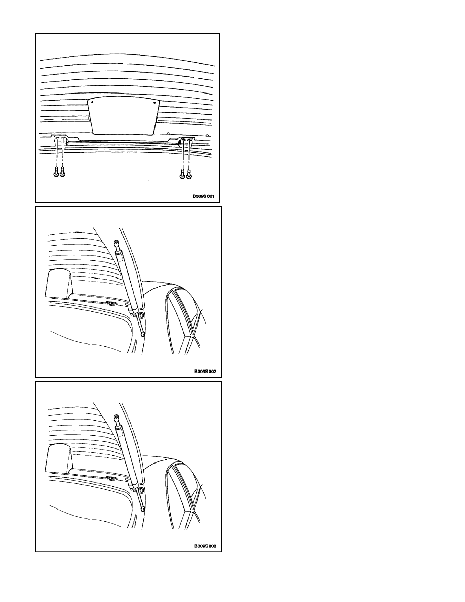
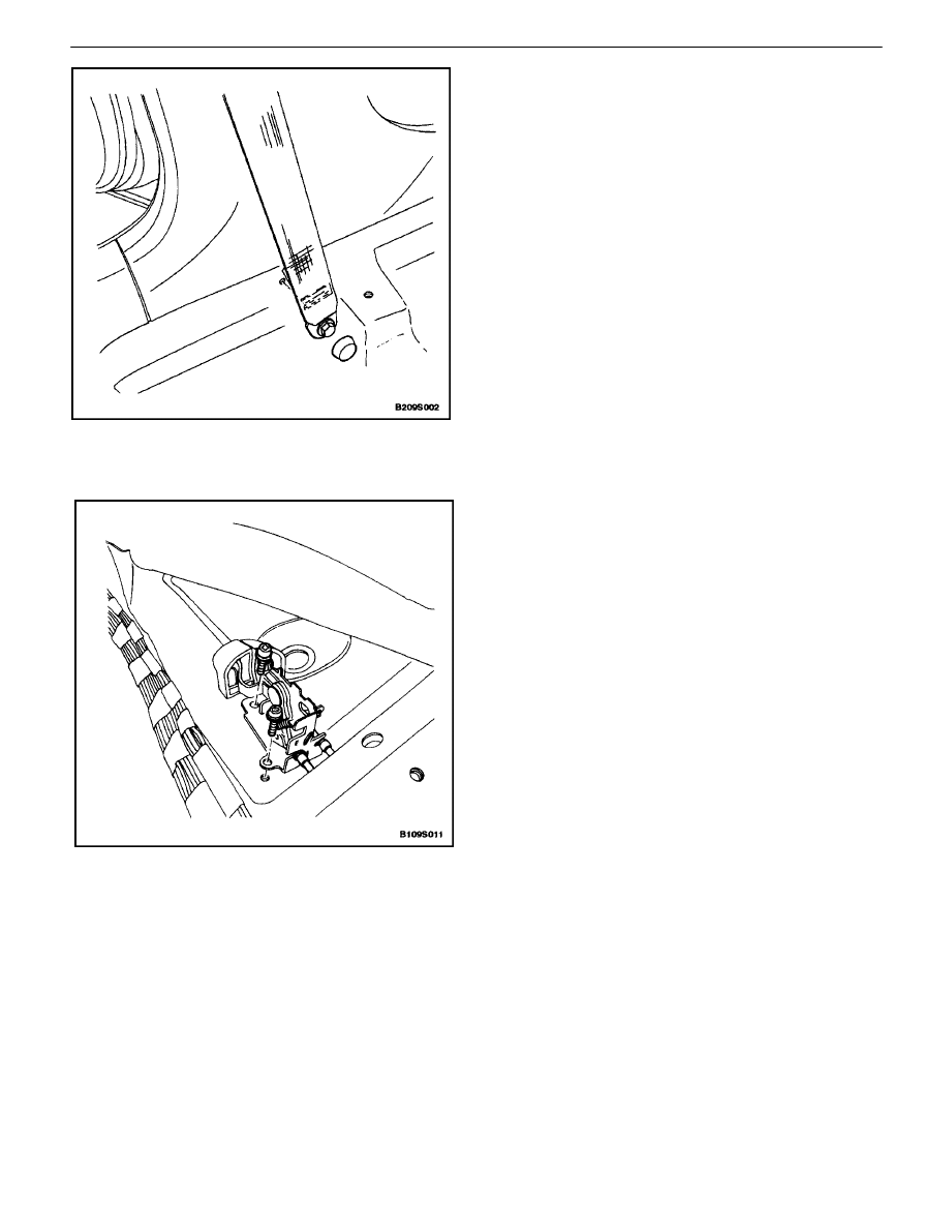
GAS SUPPORT ASSEMBLIES
(HATCHBACK)
Removal Procedure
1. Open and suitably support the hatchback door.
2. Unscrew and remove the gas support assembly
from the hatchback door and the body.
Installation Procedure
1. Install the gas support assembly onto the hatch-
back door and the body.
Tighten
Tighten the gas support assembly studs to 20 N
S
m
(15 lb–ft).
2. Close the hatchback door.
BODY REAR END 9S – 11
DAEWOO V–121 BL4
LUGGAGE COMPARTMENT LOCK
STRIKER (HATCHBACK)
Removal Procedure
1. Open the hatchback door.
2. Remove the luggage compartment rear trim panel.
Refer to Section 9G, Interior Trim.
3. Remove the screws that secure the lock striker.
Installation Procedure
1. Install the lock striker with the screws.
Tighten
Tighten the hatchback door lock striker screws to 8
N
S
m (71 lb–in).
2. Install the luggage compartment rear trim panel.
Refer to Section 9G, Interior Trim.
3. Close the hatchback door.
REAR SPOILER (HATCHBACK)
Removal Procedure
1. Open the hatchback door.
2. Remove the nuts and the rear spoiler.
9S – 12
I
BODY REAR END
DAEWOO V–121 BL4
Installation Procedure
1. Install the rear spoiler with the nuts.
Tighten
Tighten the rear spoiler nuts to 4 N
S
m (35 lb–in).
2. Close the hatchback door.
TAILGATE (WAGON)
Removal Procedure
1. Open and suitably support the tailgate.
2. Disconnect the tailgate grommets, electrical con-
nectors, and washer hose.
3. Remove the gas support assemblies from the tail-
gate. Refer to”Gas Support Assemblies (Hatch-
back)” in this section
4. With the aid of another technician, remove the bolts
and the tailgate from the hinges.
Installation Procedure
1. With the aid of another technician, install the tail-
gate to the hinges with the bolts.
Tighten
Tighten the tailgate hinge bolts to 20 N
S
m (15 lb–ft).
2. Install the gas support assemblies to the tailgate.
Refer to”Gas Support Assemblies (Hatchback)” in
this section.
3. Connect the tailgate electrical connectors, washer
hose, and grommets..
4. Close the tailgate.
BODY REAR END 9S – 13
DAEWOO V–121 BL4
GAS SUPPORT ASSEMBLIES
(WAGON)
Removal Procedure
1. Open and suitably support the tailgate.
2. Remove the bolts and the gas support assembly
from the body.
3. Unscrew and remove the gas support assembly
from the tailgate.
Installation Procedure
1. Install the gas support assembly onto the tailgate.
Tighten
Tighten the gas support assembly studs to 20 N
S
m
(15 lb–ft).
9S – 14
I
BODY REAR END
DAEWOO V–121 BL4
2. Install the gas support assembly onto the body with
the bolts.
Tighten
Tighten the gas support assembly bolts to 8 N
S
m (71
lb–in).
3. Close the tailgate.
LUGGAGE COMPARTMENT LOCK
STRIKER (WAGON)
Removal Procedure
1. Open the tailgate.
2. Remove the luggage compartment rear trim panel.
Refer to Section 9G, Interior Trim.
3. Remove the bolts that secure the lock striker.
Installation Procedure
1. Install the lock striker with the screws.
Tighten
Tighten the tailgate lock striker bolts to 10 N
S
m (89
lbin).
2. Install the luggage compartment rear trim panel.
Refer to Section 9G, Interior Trim.
3. Close the tailgate.
BODY REAR END 9S – 15
DAEWOO V–121 BL4
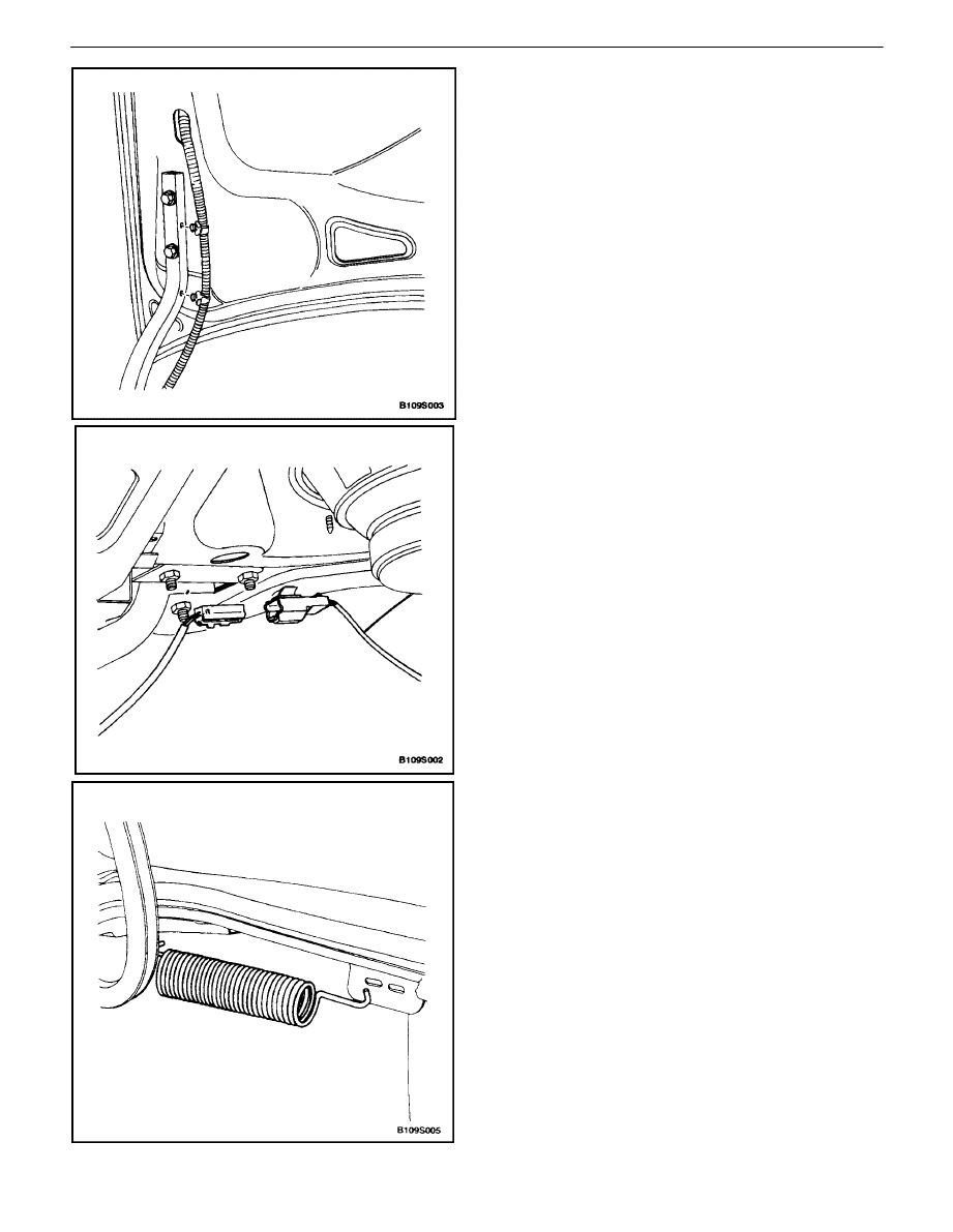
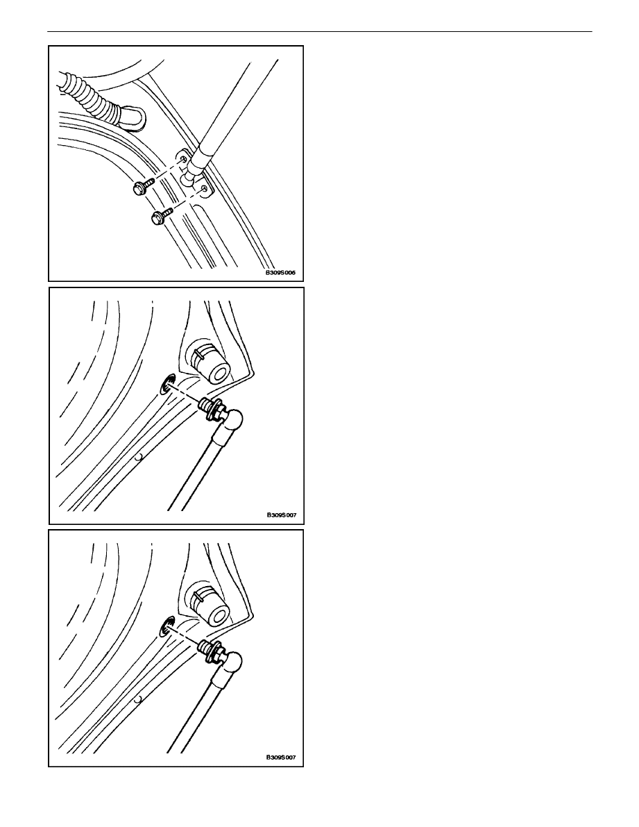
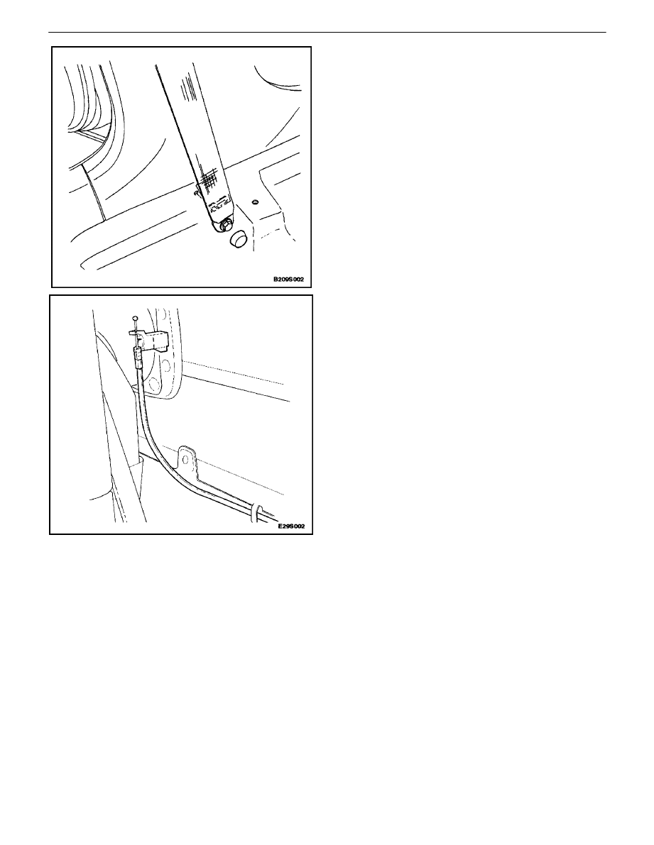
REAR DECK LID/HATCHBACK DOOR
REMOTE CABLE AND HANDLE
(NOTCHBACK)
(Notchback Shown, Hatchback
Similar)
(Left–Hand Drive Shown, Right–Hand Drive Similar)
Removal Procedure
1. Open the luggage compartment.
2. Remove the luggage compartment left side wheel-
house trim panel. Refer to Section 9G, Interior
Trim.
3. Remove the lock striker. Refer to ”Luggage
Compartment Lock Striker (Notchback)” or”Lug-
gage Compartment Lock Striker (Hatchback)” in
this section.
4. Remove the driver’s seat and the rear seat. Refer
to Section 9H, Seats.
5. Remove the lower B–pillar seat belt bolt and the
anchor.
6. Remove the rear deck lid remote handle cover.
7. Reposition the floor carpet on the left side of the
vehicle.
8. Remove the screws and the rear deck lid remote
handle.
9. Disconnect the cable from the handle.
10. Remove the cable.
9S – 16
I
BODY REAR END
DAEWOO V–121 BL4
Installation Procedure
1. Feed the cable from the luggage compartment to
the passenger compartment.
2. Connect the cable to the handle.
Notice : Dissimilar metals in direct contact with each other
may corrode rapidly. Make sure to use the correct fasten-
ers to prevent premature corrosion.
3. Install the handle with the screws.
Tighten
Tighten the rear deck lid remote cable handle screws
to 8 N
S
m (71 lb–in).
4. Install the rear deck lid remote handle cover.
5. Install the floor carpet to its original position.
6. Install the lower B–pillar seat belt anchor with the
bolt.
Tighten
Tighten the lower B–pillar seat belt bolt to 35 N
S
m (26
lb–ft).
7. Install the driver’s seat and the rear seat. Refer to
Section 9H, Seats.
8. Install the lock striker. Refer to ”Luggage Compart-
ment Lock Striker (Notchback)” or”Luggage
Compartment Lock Striker (Hatchback)” in this sec-
tion.
9. Install the luggage compartment left side wheel-
house trim panel. Refer to Section 9G, Interior
Trim.
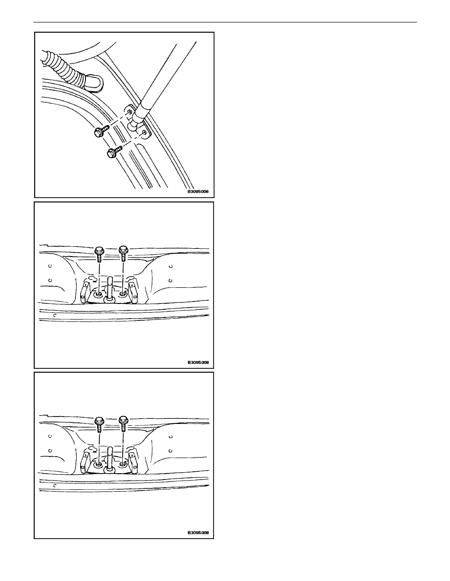
FUEL FILLER DOOR REMOTE CABLE
AND HANDLE
(Notchback Shown, Hatchback and
Wagon Similar)
(Left–Hand Drive Shown, Right–Hand Drive Similar)
Removal Procedure
1. Open the luggage compartment.
2. Remove the luggage compartment wheelhouse trim
panels. Refer to Section 9G, Interior Trim.
3. Disconnect the cable from the fuel filler door.
BODY REAR END 9S – 17
DAEWOO V–121 BL4
4. Remove the front seat and the rear seats. Refer to
Section 9H, Seats.
5. Remove the lower B–pillar seat belt bolt and the
anchor.
6. Remove the rear deck lid remote handle cover.
7. Reposition the floor carpet on the left side of the
vehicle.
8. Remove the screws and the fuel filler door remote
handle.
9. Disconnect the cable from the handle.
10. Remove the cable.
Installation Procedure
1. Feed the cable from the luggage compartment to
the passenger compartment.
2. Connect the cable to the handle.
3. Install the handle with the screws.
Tighten
Tighten the fuel filler door remote cable handle screws
to 8 N
S
m (71 lb–in).
9S – 18
I
BODY REAR END
DAEWOO V–121 BL4
4. Install the floor carpet to its original position.
5. Install the lower B–pillar seat belt anchor with the
bolt.
Tighten
Tighten the lower B–pillar seat belt anchor bolt to 35
N
S
m (26 lb–ft).
6. Install the front seat and the rear seat. Refer to
Section 9H, Seats.
7. Connect the cable to the fuel filler door.
8. Install the luggage compartment wheelhouse trim
panels. Refer to Section 9G, Interior Trim.

BODY REAR END 9S – 19
DAEWOO V–121 BL4
GENERAL DESCRIPTION
AND SYSTEM OPERATION
FUEL FILLER DOOR
The fuel filler door attaches to the fuel tank pocket on the
right side of the vehicle. The door is opened by pulling on
the fuel filler door remote handle located on the floor in
front of the driver’s seat.
REAR DECK LID (NOTCHBACK)
The rear deck lid consists of an inner and outer panel that
is hemmed around the perimeter and bonded together
with structural adhesive. The deck lid springs assist in the
opening of the rear deck lid and hold it in the open position.
HATCHBACK DOOR
The hatchback door consists of the rear hatch glass within
a steel frame. The steel frame is made of an inner and out-
er panel hemmed around the perimeter and bonded to-
gether with structural adhesive. The gas support assem-
blies assist in the opening of the hatchback door and can
hold it in the open position.
TAILGATE (WAGON)
The tailgate is made of a steel frame which contains the
rear glass. The steel frame is made of an inner and outer
panel hemmed around the perimeter and bonded together
with structural adhesive. The gas support assemblies as-
sist in the opening of the tailgate and can hold it in the open
position.
Wyszukiwarka
Podobne podstrony:
M39s Body Rear End
BODY FRONT END SECTION 9R 14
M39r Body Front End
Rear End
ENGINE COOLING SECTION 1D 19
CRUISE CONTROL SECTION 9U 19
BODY WIRING SYSTEM SECTION 9A 11
19 Health, diseases, human body
19 Rear Air Conditioning
Wyk ECiUL#9S 2013
więcej podobnych podstron