
DAEWOO M-150 BL2
SECTION 9R
BODY FRONT END
TABLE OF CONTENTS
Description and Operation
9R-2
. . . . . . . . . . . . . . . . . .
Body Front End
9R-2
. . . . . . . . . . . . . . . . . . . . . . . . . . .
Repair Instructions
9R-3
. . . . . . . . . . . . . . . . . . . . . . . . .
On-Vehicle Service
9R-3
. . . . . . . . . . . . . . . . . . . . . . . . . .
Lubrication
9R-3
. . . . . . . . . . . . . . . . . . . . . . . . . . . . . . .
Fasteners
9R-3
. . . . . . . . . . . . . . . . . . . . . . . . . . . . . . . .
Anticorrosion Materials
9R-3
. . . . . . . . . . . . . . . . . . . . .
Front End Sealing
9R-4
. . . . . . . . . . . . . . . . . . . . . . . . .
Cowl Vent Grille
9R-4
. . . . . . . . . . . . . . . . . . . . . . . . . . .
Hood
9R-5
. . . . . . . . . . . . . . . . . . . . . . . . . . . . . . . . . . . .
Hood Hinge
9R-5
. . . . . . . . . . . . . . . . . . . . . . . . . . . . . . .
Hood Prop Rod
9R-6
. . . . . . . . . . . . . . . . . . . . . . . . . . .
Hood Latch
9R-7
. . . . . . . . . . . . . . . . . . . . . . . . . . . . . . .
Hood Latch Release Lever
9R-8
. . . . . . . . . . . . . . . . . .
Hood Latch Release Cable
9R-9
. . . . . . . . . . . . . . . . .
Fender
9R-9
. . . . . . . . . . . . . . . . . . . . . . . . . . . . . . . . . . .

9R – 2 BODY FRONT END
DAEWOO M-150 BL2
DESCRIPTION AND OPERATION
BODY FRONT END
This vehicle has a unitized body with a frame assembly
supporting the engine and the transaxle. The fender
panels and the radiator support are also integral parts of
the body.
BODY FRONT END 9R – 3
DAEWOO M-150 BL2
REPAIR INSTRUCTIONS
ON–VEHICLE SERVICE
D109C517
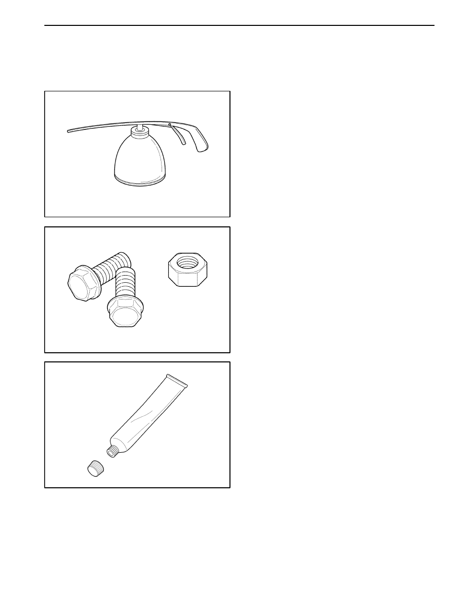
LUBRICATION
The hood hinges and the locking mechanisms require
periodic lubrication for proper operation. Refer to Sec-
tion 0B, General Information for the specific types and
intervals of lubrication.
D109C518
FASTENERS
Notice: Dissimilar metals in direct contact with each
other may corrode rapidly. Make sure to use the correct
fasteners to prevent premature corrosion.
Many aluminum components are used on current models.
Aluminum in contact with steel may corrode rapidly if it is
not protected by special finishes or isolators.
The fasteners used have a special finish which provides
adequate protection from corrosion. These special fas-
teners differ in color in order to easily identify them from
the standard metric fasteners, which are medium blue in
color.
When replacing fasteners, avoid substituting otherwise
similar fasteners in the same location.
D109C519
ANTICORROSION MATERIALS
In order to provide rust resistance, anticorrosion materi-
als have been applied to the interior surfaces of most
of the metal panels. When you service these panels,
properly re-coat them with a service-type anticorrosion
material if any of the original material has been dis-
turbed.
9R – 4 BODY FRONT END
DAEWOO M-150 BL2
D109C520
FRONT END SEALING
All locations where waterleaks may occur are sealed
during production with high quality, durable sealers. If it
becomes necessary to reseal specific areas, use a high
quality sealer of medium-bodied consistency which will
retain its flexible characteristics after curing and can be
painted if necessary.
D109C521
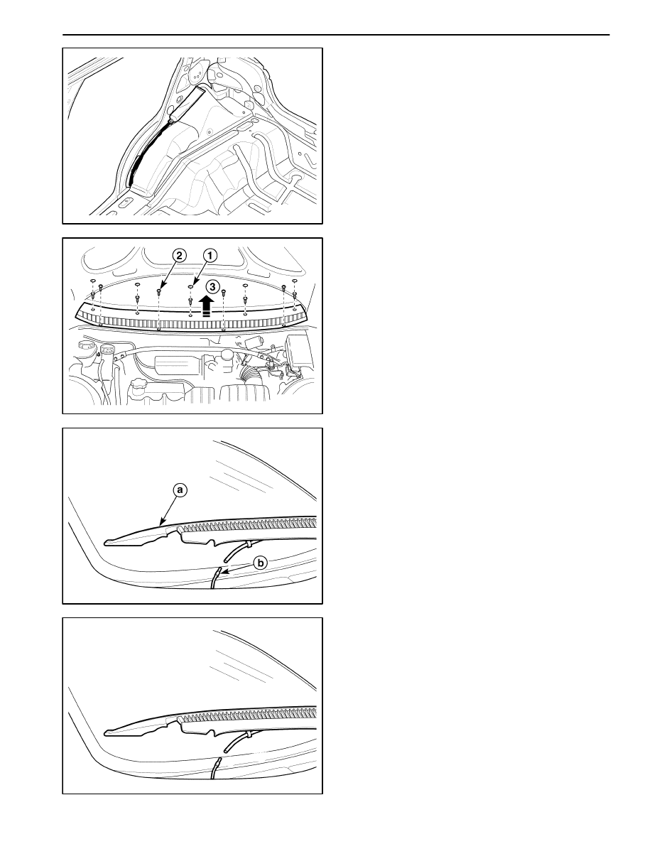
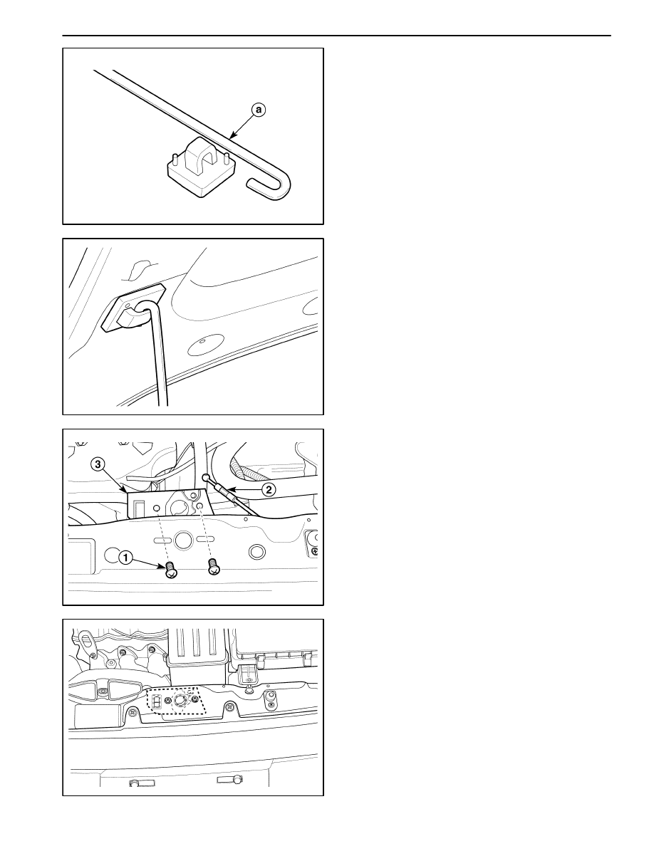
COWL VENT GRILLE
Removal Procedure
1. Remove the wiper arm assembly. Refer to Section
9D, Wiper/Washer Systems.
2. Remove the cowl vent grille screws and the clips.
D
Remove the screws after removing the upper cap
(1).
D
Remove the lower retaining plastic clips (2).
D
Close the hood.
D
Lift up the cowl vent grille (3).
D19C522A
3. Remove the cowl vent grille.
D
Disconnect the front washer hose connector.
D
Remove the cowl vent grille.
a. Cowl vent grille.
b. Front washer hose connector.
D19C522A
Installation Procedure
1. Connect the front washer hose connector.
BODY FRONT END 9R – 5
DAEWOO M-150 BL2
D109C523
2. Install the cowl vent grille with the screws and the
clips.
3. Install the wiper arm assembly. Refer to Section 9D,
Wiper/Washer Systems.
D109C524
HOOD
Removal Procedure
Important: Install the protective coverings over the
fenders and the windshield in order to prevent damage
to the paint, the glass and the moldings when you are
removing and installing the hood.
1. Raise and support the hood.
2. Remove the hood.
D
Remove the bolts (1).
D
Remove the hood (2).
D109C525
Installation Procedure
Notice: Dissimilar metals in direct contact with each
other may corrode rapidly. Make sure to use the correct
fasteners to prevent premature corrosion.
1. Install the hood with the bolts.
2. Inspect the hood for proper alignment.
D109C526
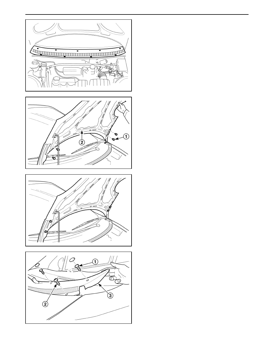
HOOD HINGE
Removal Procedure
1. Remove the hood. Refer to “Hood” in this section.
2. Take off the cowl vent grille.
D
Remove the screws after removing the upper caps
(1).
D
Remove the retaining screw on the cowl vent grille
(2).
D
Take off the cowl vent grill (3).
9R – 6 BODY FRONT END
DAEWOO M-150 BL2
D19C527A
3. Remove the bolts on the top of the fender.
a. Fender upper mounting bolt.
D109C528
4. Remove the hood hinge.
D
Remove the bolts (1).
D
Remove the hood hinge (2).
D109C529
Installation Procedure
Notice: Dissimilar metals in direct contact with each
other may corrode rapidly. Make sure to use the correct
fasteners to prevent premature corrosion.
1. Install the hood hinge with the bolts.
2. Install the bolts along the top of the fender.
3. Install the cowl vent grille with the screws and the
caps.
4. Install the hood. Refer to “Hood” in this section.
D109C530
HOOD PROP ROD
Removal Procedure
1. Support the hood in the open position.
2. Remove the hood prop from the hood.
D
Using a sharp gimlet, press the pins (1).
D
Remove the hood prop (2).
BODY FRONT END 9R – 7
DAEWOO M-150 BL2
D109C531
3. Remove the hood prop rod from the hood prop.
a. Hood prop rod.
D109C532
Installation Procedure
1. Install the hood prop rod to the hood prop.
2. Install the hood prop to the hood with the pins.
D109C533
HOOD LATCH
Removal Procedure
1. Open the hood.
2. Remove the hood latch.
D
Remove the screws (1).
D
Disconnect the hood latch release cable (2).
D
Remove the hood latch (3).
D109C534
Installation Procedure
1. Connect the hood latch release cable to the latch.
Notice: Dissimilar metals in direct contact with each
other may corrode rapidly. Make sure to use the correct
fasteners to prevent premature corrosion.
2. Install the hood latch with the screws.
9R – 8 BODY FRONT END
DAEWOO M-150 BL2
D109C535
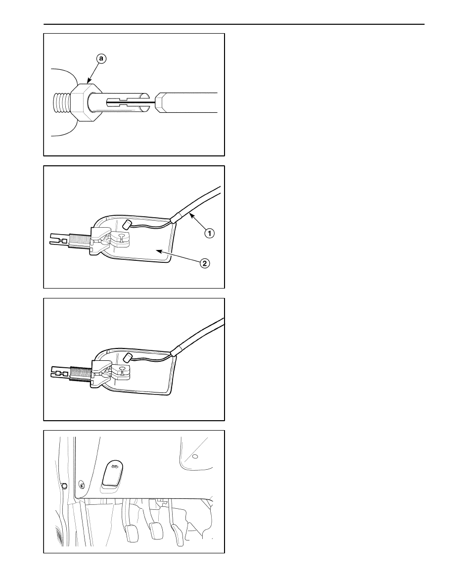
HOOD LATCH RELEASE LEVER
(Left–Hand Drive Shown, Right–Hand
Drive Similar)
Removal Procedure
1. Remove the hood latch nut into the instrument panel.
a. Hood latch nut.
D109C536
2. Remove the hood latch release lever.
D
Disconnect the cable (1).
D
Remove the hood latch release lever (2).
D19C536A
Installation Procedure
1. Connect the hood latch release cable to the hood
latch lever.
D109C537
Notice: Dissimilar metals in direct contact with each
other may corrode rapidly. Make sure to use the correct
fasteners to prevent premature corrosion.
2. Install the hood latch lever release to the instrument
panel with the hood latch nut.
BODY FRONT END 9R – 9
DAEWOO M-150 BL2
D109C538
HOOD LATCH RELEASE CABLE
(Left–Hand Drive Shown, Right–Hand
Drive Similar)
Removal Procedure
1. Remove the hood latch release cable from the instru-
ment panel. Refer to “Hood Latch Release Lever” in
this section.
2. Push the cable toward the engine compartment
through the body hole.
a. Hood latch lever cable.
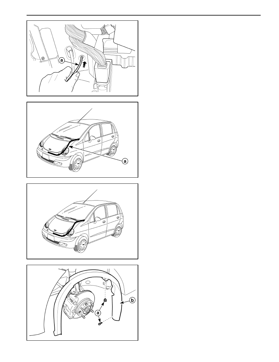
D19C539B
3. Open and suitably support the hood.
4. Disconnect the hood latch release cable from the
hood latch. Refer to “Hood Latch” in this section.
5. Remove the hood latch release cable after removing
the plastic strip.
a. Hood latch release cable.
D19C539C
Installation Procedure
1. Connect the hood latch release cable to the hood
latch. Refer to “Hood Latch” in this section.
2. Arrange the hood latch release cable with the plastic
strip.
3. Push the cable toward the passenger compartment
through the body hole.
4. Connect the hood latch release cable to the hood
latch release lever. Refer to “Hood Latch Release Le-
ver” in this section.
D19C501A
FENDER
Removal Procedure
1. Raise and suitably support the vehicle.
2. Remove the wheelhouse splash shield.
D
Remove the clip and the bolt.
a. Clip and bolt.
D
Remove the wheel house splash shield.
a. Wheel house splash shield.
9R – 10 BODY FRONT END
DAEWOO M-150 BL2
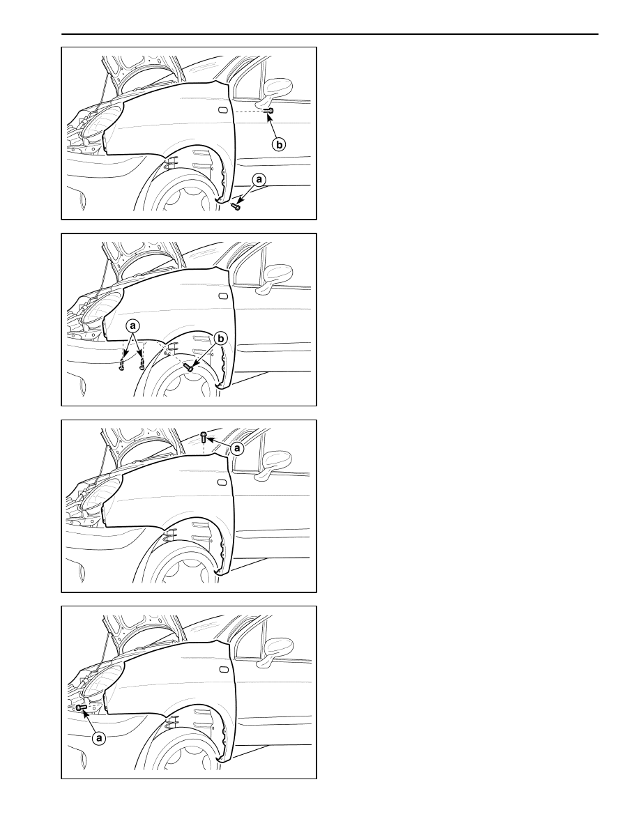
D19C540A
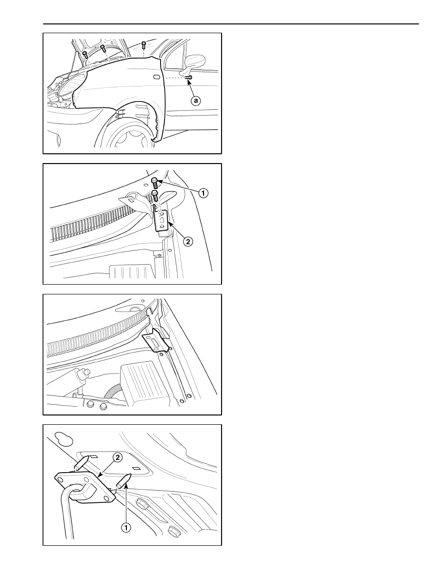
3. Remove the bolt at the base of the fender.
a. Fender mounting lower bolt.
4. Open the front door. Remove the bolt on the A–pillar.
b. Fender mounting bolt.
D19C541A
5. Remove the screws on the side of the front bumper
fascia.
a. Bumper fascia side bolts.
6. Remove the bolt under the fender.
b. Fender mounting bolt.
D19C542A
7. Lower the vehicle.
8. Take off the cowl vent grille. Remove the bolt on the
top of the fender.
a. Fender mounting bolt.
D19C543A
9. Remove the front bumper spacer. Refer to Section
9M, Exterior Trim.
10. Remove the fender front bolt.
a. Fender front bolt.
BODY FRONT END 9R – 11
DAEWOO M-150 BL2
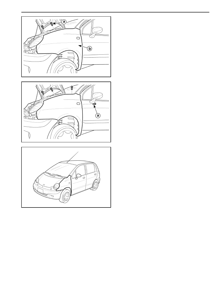
D19C544A
11. Remove the bolts along the top of the fender.
a. Bolt.
12. Remove the fender.
b. Fender.
D19C527A
Installation Procedure
1. Install the fender.
Notice: Dissimilar metals in direct contact with each
other may corrode rapidly. Make sure to use the correct
fasteners to prevent premature corrosion.
2. Install the bolts along the top of the fender.
D19C545A
3. Install the front bumper spacer.
4. Install the cowl vent grille.
5. Raise and suitably support the vehicle.
6. Install the bolts under the fender.
7. Install the screws on the side of the front bumper
fascia.
8. Open the front door Install the bolt on the A–pillar.
9. Install the bolt at the base of the fender.
10. Install the wheelhouse splash shield with the
screws.
11. Lower the vehicle.
Wyszukiwarka
Podobne podstrony:
BODY FRONT END SECTION 9R 14
Front End Replacing Tie Rod Ends
Front End Alignment Basics
Front End Replacing Ball Joints
Front End Alignment Tests For
M39s Body Rear End
Front End
FRONT END 28072004
FT 221 FT 225 Mutek Front end
BODY REAR END SECTION 9S 19
2002 09 Creating Virtual Worlds with Pov Ray and the Right Front End
Front End
więcej podobnych podstron