
SECTION : 9R
BODY FRONT END
TABLE OF CONTENTS
SPECIFICATIONS
9R–1
. . . . . . . . . . . . . . . . . . . . . . . . . .
FASTENER TIGHTENING SPECIFICATIONS
9R–1
.
MAINTENANCE AND REPAIR
9R–2
. . . . . . . . . . . . . . .
ON–VEHICLE SERVICE
9R–2
. . . . . . . . . . . . . . . . . . . . .
LUBRICATION
9R–2
. . . . . . . . . . . . . . . . . . . . . . . . . . . .
FASTENERS
9R–2
. . . . . . . . . . . . . . . . . . . . . . . . . . . . .
ANTICORROSION MATERIALS
9R–2
. . . . . . . . . . . . .
FRONT END SEALING
9R–2
. . . . . . . . . . . . . . . . . . . .
COWL VENT GRILLE
9R–2
. . . . . . . . . . . . . . . . . . . . . .
HOOD
9R–4
. . . . . . . . . . . . . . . . . . . . . . . . . . . . . . . . . . .
HOOD HINGES
9R–4
. . . . . . . . . . . . . . . . . . . . . . . . . . .
HOOD PROP ROD
9R–5
. . . . . . . . . . . . . . . . . . . . . . . .
HOOD SECONDARY LATCH
9R–6
. . . . . . . . . . . . . . .
HOOD LATCH RELEASE CABLE
9R–6
. . . . . . . . . . . .
RADIATOR GRILLE
9R–8
. . . . . . . . . . . . . . . . . . . . . . . .
FENDER
9R–9
. . . . . . . . . . . . . . . . . . . . . . . . . . . . . . . . .
GENERAL DESCRIPTION AND SYSTEM
OPERATION
9R–14
. . . . . . . . . . . . . . . . . . . . . . . . . . . . .
BODY FRONT END
9R–14
. . . . . . . . . . . . . . . . . . . . . .
SPECIFICATIONS
FASTENER TIGHTENING SPECIFICATIONS
Application
N
S
m
Lb–Ft
Lb–In
A–Pillar Fender Bolt
8
–
71
Cowl Vent Grille Screws
4
–
35
Fender Bolt (Front of Fas-
cia)
4
–
35
Front Bumper Fascia–to–
Fender Bolt
1.5
–
13
Hinge Bolts
27
20
–
Hood–to–Hinge Bolts
27
20
–
Hood Latch Bolts
8
–
71
Hood Release Handle Nuts
4
–
35
Lower Fender Bolt
8
–
71
Radiator Grille Nuts
4
–
35
Splash Shield Bolts
1.5
–
13
Upper Fender Bolts
8
–
71
9R – 2
I
BODY FRONT END
DAEWOO V–121 BL4
MAINTENANCE AND REPAIR
ON–VEHICLE SERVICE
LUBRICATION
The hood hinges and the locking mechanisms require pe-
riodic lubrication for proper operation. Refer to Section 0B,
General Information for the specific types and intervals of
lubrication.
FASTENERS
Notice : Dissimilar metals in direct contact with each other
may corrode rapidly. Make sure to use the correct fasten-
ers to prevent premature corrosion.
Many aluminum components are used on current models.
Aluminum in contact with steel may corrode rapidly if it is
not protected by special finishes or isolators.
The fasteners used have a special finish which provides
adequate protection from corrosion. These special fasten-
ers differ in color in order to easily identify them from the
standard metric fasteners, which are medium blue.
When replacing fasteners, avoid substituting otherwise
similar fasteners in the same location.
ANTICORROSION MATERIALS
In order to provide rust resistance, anticorrosion materials
have been applied to the interior surfaces of most of the
metal panels. When you service these panels, properly re-
coat them with a service–type anticorrosion material if any
of the original material has been disturbed.
FRONT END SEALING
All locations where waterleaks may occur are sealed dur-
ing production with high quality, durable sealers. If it be-
comes necessary to reseal specific areas, use a highqual-
ity sealer of medium–bodied consistency which will retain
its flexible characteristics after curing and can be painted,
if necessary.
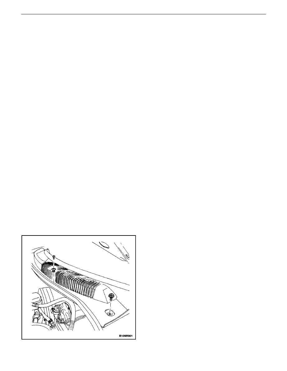
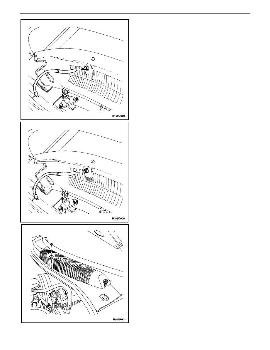
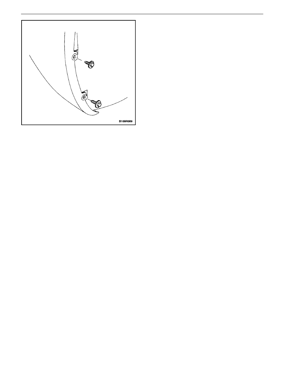
COWL VENT GRILLE
(Left–Hand Drive Shown, Right–Hand
Drive Similar)
Removal Procedure
1. Raise the hood and support it with the hood prop.
2. Remove the wiper arms. Refer toSection 9D, Wip-
ers/ Washer Systems.
3. Remove the cowl vent grille screws and the two–
piece grille.
BODY FRONT END 9R – 3
DAEWOO V–121 BL4
4. Disconnect the washer hoses.
Installation Procedure
1. Connect the washer hoses.
Notice : Dissimilar metals in direct contact with each other
may corrode rapidly. Make sure to use the correct fasten-
ers to prevent premature corrosion.
2. Install the two–piece grille and the cowl vent grille
screws.
Tighten
Tighten the cowl vent grille screws to 4 N
S
m (35 lbin).
3. Install the wiper arms. Refer to Section 9D, Wipers/
Washer Systems.
9R – 4
I
BODY FRONT END
DAEWOO V–121 BL4
HOOD
Removal Procedure
Notice : Install protective coverings over the fenders and
the windshield in order to prevent damage to the paint, the
glass and the moldings when you are removing and instal-
ling the hood.
1. Raise and support the hood.
2. Mark the position of the hinge to the hood to facili-
tate alignment during installation.
3. Remove the bolts that retain the hood to both
hinges.
4. With the aid of another technician, remove the hood
from the hinges.
Installation Procedure
1. With the aid of another technician, position the
hood in the location marked during removal.
Notice : Dissimilar metals in direct contact with each other
may corrode rapidly. Make sure to use the correct fasten-
ers to prevent premature corrosion.
2. Install the two bolts securing the hood to each
hinge.
Tighten
Tighten the hood–to–hinge bolts to 27 N
S
m (20 lb–ft).
3. Inspect the hood for proper alignment.
HOOD HINGES
Removal Procedure
1. Remove the hood. Refer to”Hood” in this section.
2. Remove the bolts and the hinge.
BODY FRONT END 9R – 5
DAEWOO V–121 BL4
Installation Procedure
Notice : Dissimilar metals in direct contact with each other
may corrode rapidly. Make sure to use the correct fasten-
ers to prevent premature corrosion.
1. Install the hinge with the bolts.
Tighten
Tighten the hinge bolts to 27 N
S
m (20 lb–ft).
2. Install the hood. Refer to”Hood” in this section.
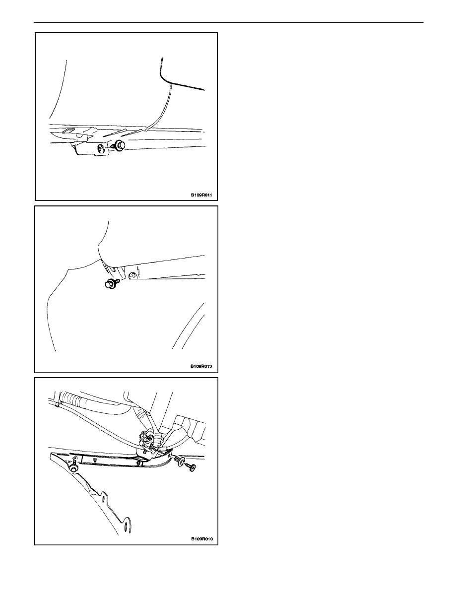
HOOD PROP ROD
Removal Procedure
1. Support the hood in the open position.
2. Remove the hood prop rod by gently prying the
base from the radiator support.
Installation Procedure
1. Install the hood prop rod by snapping the base back
into the radiator support.
9R – 6
I
BODY FRONT END
DAEWOO V–121 BL4
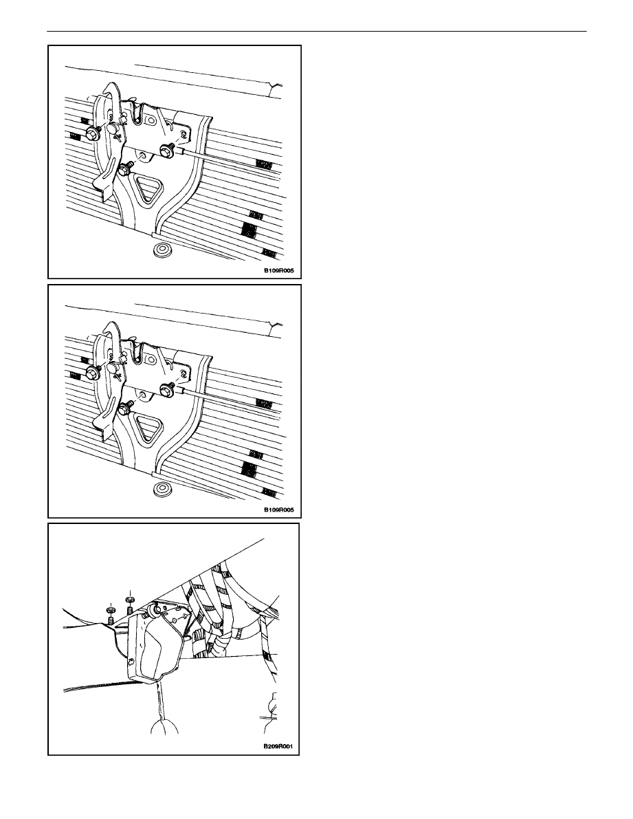
HOOD SECONDARY LATCH
(Left–Hand Drive Shown, Right–Hand
Drive Similar)
Removal Procedure
1. Open the hood.
2. Mark the position of the hood latch on the radiator
support to facilitate alignment during installation.
3. Remove the bolts and the hood latch.
4. Disconnect the hood release cable.
Installation Procedure
Notice : Dissimilar metals in direct contact with each other
may corrode rapidly. Make sure to use the correct fasten-
ers to prevent premature corrosion.
1. Connect the hood release cable to the latch.
2. Position the hood latch in the location marked dur-
ing removal.
3. Install the hood latch with the bolts.
Tighten
Tighten the hood latch bolts to 8 N
S
m (71 lb–in).
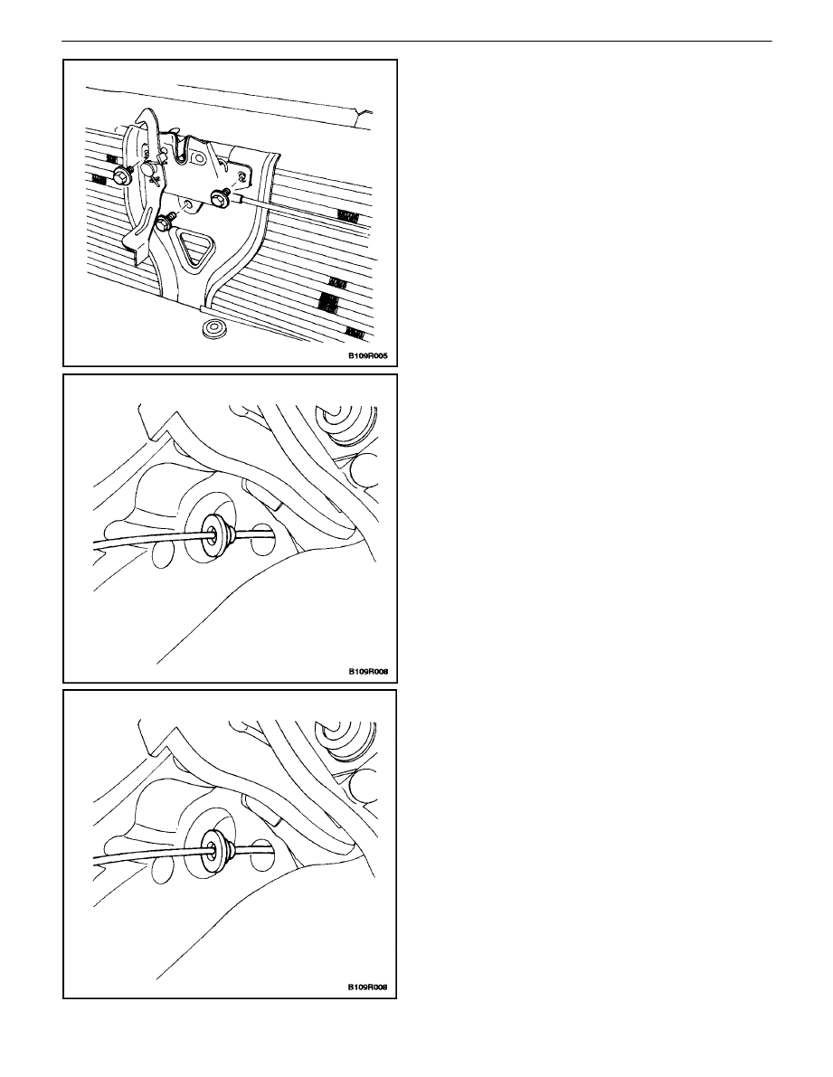
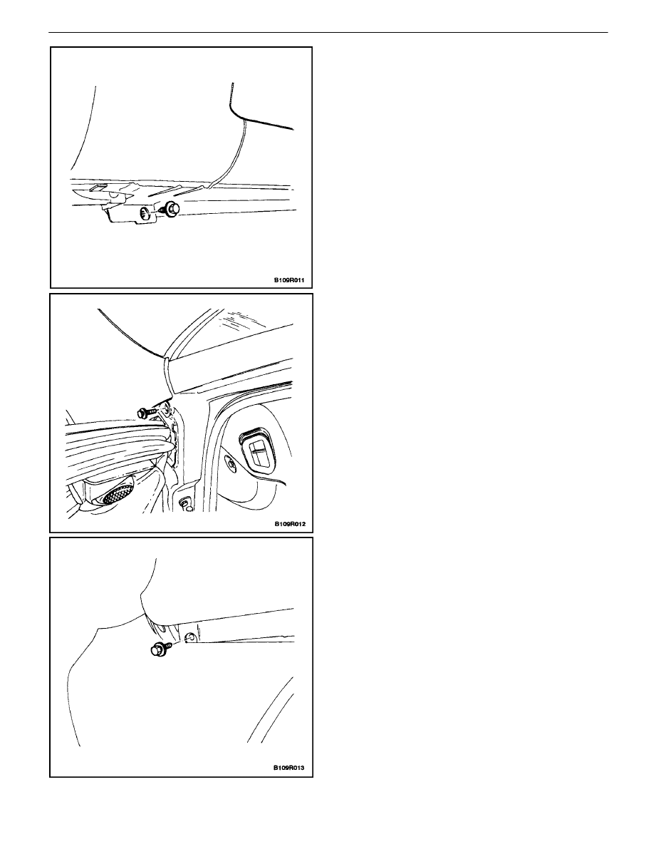
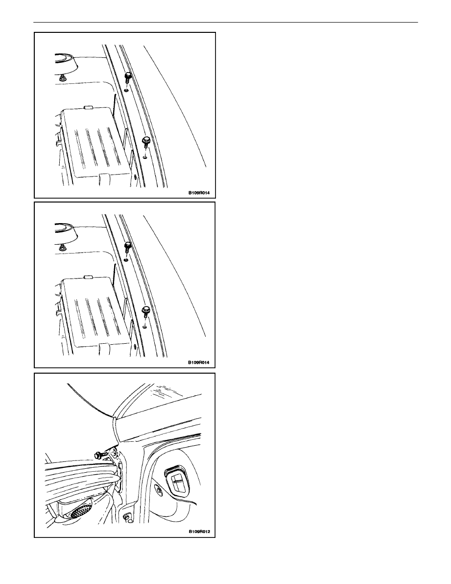
HOOD LATCH RELEASE CABLE
(Left–Hand Drive Shown, Right–Hand
Drive Similar)
Removal Procedure
1. Remove the nuts and the hood release handle from
the instrument panel.
BODY FRONT END 9R – 7
DAEWOO V–121 BL4
2. Open the hood.
3. Remove the bolts and the hood latch release.
4. Remove the cable from the hood latch release as-
sembly.
5. Remove the cable and the grommet from inside the
vehicle.
Installation Procedure
Notice : Dissimilar metals in direct contact with each other
may corrode rapidly. Make sure to use the correct fasten-
ers to prevent premature corrosion.
1. Install the cable through the engine compartment.
2. Install the cable into the hood latch release handle.
3. Install the grommet in the fire wall.
9R – 8
I
BODY FRONT END
DAEWOO V–121 BL4
4. Install the hood release handle on the instrument
panel with the nuts.
Tighten
Tighten the hood latch bolts to 8 N
S
m (71 lb–in).
5. Install the cable to the hood latch release assembly.
6. Install the hood latch release assembly with the
bolts.
Tighten
Tighten the hood latch bolts to 8 N
S
m (71 lb–in).
RADIATOR GRILLE
Removal Procedure
1. Open the hood.
2. Remove the nuts and the radiator grille.
BODY FRONT END 9R – 9
DAEWOO V–121 BL4
Installation Procedure
Notice : Dissimilar metals in direct contact with each other
may corrode rapidly. Make sure to use the correct fasten-
ers to prevent premature corrosion.
1. Install the radiator grille with the nuts.
Tighten
Tighten the radiator grille nuts to 4 N
S
m (35 lb–in).
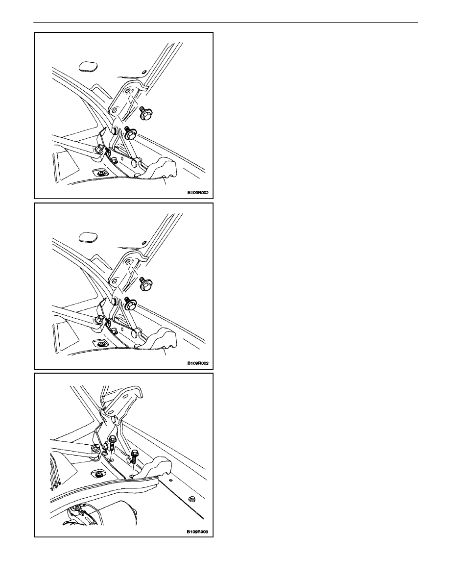
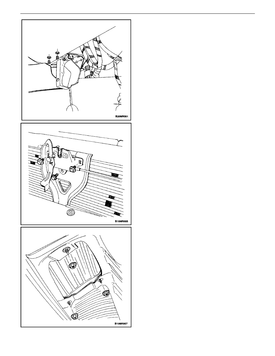
FENDER
Removal Procedure
1. Raise and suitably support the vehicle.
2. Remove the front wheel. Refer toSection 2E, Tires
and Wheels.
3. Remove the screws, the bolts, and the front wheel
well splash shield.
4. Remove the side turn signal lamp. Refer to Section
9B, Lighting Systems.
5. Remove the screw and the bolt that secure the
front bumper fascia to the fender.
9R – 10
I
BODY FRONT END
DAEWOO V–121 BL4
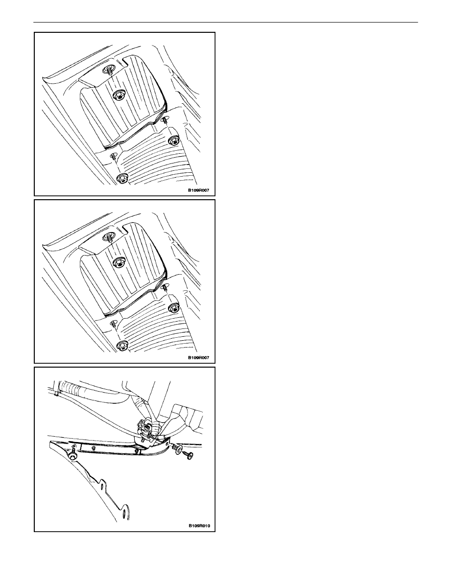
6. Remove the bolt at the base of the fender.
7. Open the front door.
8. Remove the bolt at the base of the A–pillar.
9. Open the hood.
10. Remove the headlamp. Refer to Section 9B, Light-
ing Systems.
11. Remove the bolt between the bumper fascia and
the fender.
BODY FRONT END 9R – 11
DAEWOO V–121 BL4
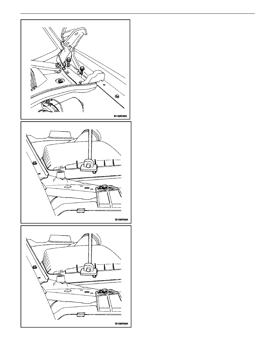
12. Remove the bolts along the top of the fender.
13. Remove the fender.
Installation Procedure
1. Install the headlamp. Refer to Section 9B, Lighting
Systems.
2. Install the fender.
Notice : Dissimilar metals in direct contact with each other
may corrode rapidly. Make sure to use the correct fasten-
ers to prevent premature corrosion.
3. Install the bolts along the top of the fender.
Tighten
Tighten the upper fender bolts to 8 N
S
m (71 lb–in).
4. Install the bolt at the base of the A–pillar.
Tighten
Tighten the A–pillar fender bolt to 8 N
S
m (71 lb–in).
9R – 12
I
BODY FRONT END
DAEWOO V–121 BL4
5. Install the bolt at the base of the fender.
Tighten
Tighten the lower fender bolt to 8 N
S
m (71 lb–in).
6. Install the bolt between the bumper fascia and the
fender.
Tighten
Tighten the fender bolt on the front of the fascia to 4
N
S
m (35 lb–in).
7. Install the fender to the front bumper fascia with the
screw and the bolt.
Tighten
Tighten the front bumper fascia–to–fender bolt to 1.5
N
S
m (13 lb–in).
BODY FRONT END 9R – 13
DAEWOO V–121 BL4
8. Install the side turn signal lamp. Refer to Section
9B, Lighting Systems.
9. Install the front wheel well splash shield with the
screws and the bolts.
Tighten
Tighten the splash shield bolts to 1.5 N
S
m (13 lb–in).
10. Install the front wheel. Refer to Section 2E, Tires
and Wheels.
11. Lower the vehicle.

9R – 14
I
BODY FRONT END
DAEWOO V–121 BL4
GENERAL DESCRIPTION
AND SYSTEM OPERATION
BODY FRONT END
This vehicle has a unitized body with a frame assembly
supporting the engine and the transaxle. The fender pan-
els and the radiator support are also integral parts of the
body.
Wyszukiwarka
Podobne podstrony:
M39r Body Front End
BODY REAR END SECTION 9S 19
Front End Replacing Tie Rod Ends
Front End Alignment Basics
Front End Replacing Ball Joints
Front End Alignment Tests For
M39s Body Rear End
Front End
FRONT END 28072004
FT 221 FT 225 Mutek Front end
ENGINE CONTROLS SECTION 1F 14
BUMPERS & FASCIAS SECTION 9O 1 14
2002 09 Creating Virtual Worlds with Pov Ray and the Right Front End
więcej podobnych podstron