
FRONT END 28072004.doc
1
FRONT END
Corrections
28 JULY 2004
1
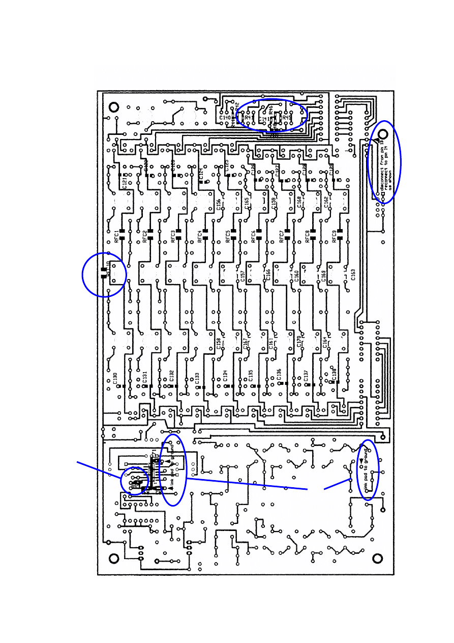
Remember the corrections that must be done on the solder side of the board.
2
RFC10 is not on the schematic or the parts list. Should also be approx. 1 uH.
3
C68 and C69 has no ground connection on the board. Must be done. C68 is SMD
4
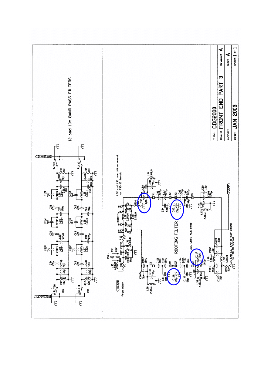
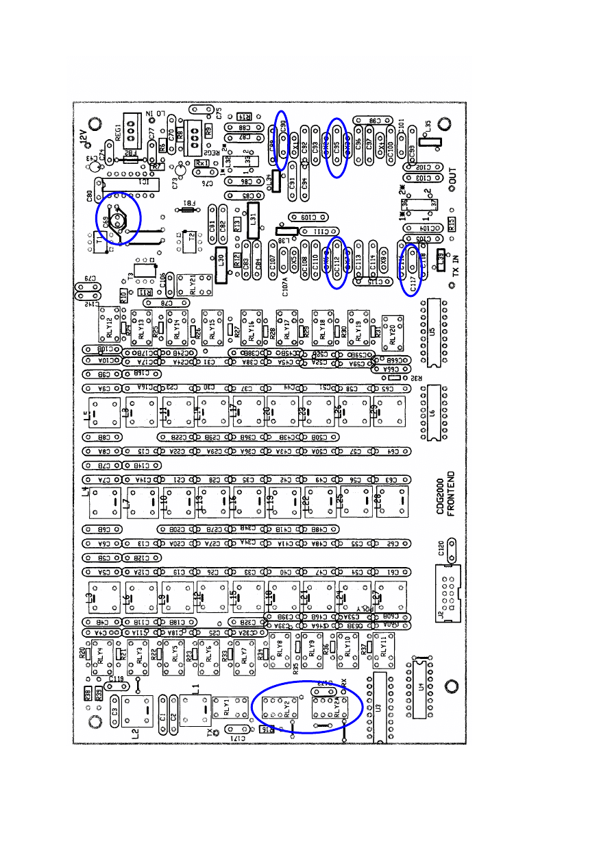
Roofing circuitry, a few changes have been done on my board. These changes could
be caused the deviating parameters of the x-tals (I guess). The corrections were all
done with the purpose of getting the filter curve to look good-meaning low inserting
loss, minimum ripple and symmetrical with an acceptable bandwidth.
A
C112 and C95are now in the range of 68-78pF.
B
C117 and C90 are now appr. 22pF.
After these modifications have been done, the results are shown on the following
pages.
5
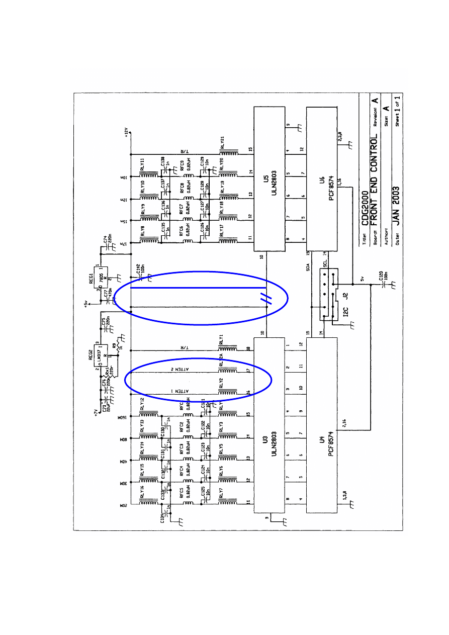
During the testing of the frontend board I found that the relay RLY2A
had the coil reversed. The + end of the coil should in fact go to
+12V and not to the ULN2803.
RLY2´s + end should also go to +12V and not to to pin 18 of the
ULN2803.
Now I got the relays to activate - but in a wrong way. The track to
pin 16 should go to pin 17 and the track to pin 17 should go to pin
16.
Doing this means that the displayed attenuation o-6-12-18 dB and S-
meter readings now works.
A lot of measurements have been done on the roofing filter. I was not satisfied with the symmetry
and the ripple. Trying to change values was not a success. It seems difficult to adjust in general. I
did not measure the x-tals, so I do not know how accurate they are. I assume they are not of the
highest quality.
One trick that – for me – solved all problems was to eliminate the x-tal Co (or most of it) be means
of a choke and then adjust the capacitors. Now it is possible to change everything. The center
frequency, the passband and the ripple can now - with some patience - be adjusted to optimum for
both channels. The chokes I used were 68uH from Farnell (513-519). I tried other chokes, but this
one worked ufb. The chokes were soldered directly across every x-tal .
The values I have found may not be optimum with your x-tals To adjust the filter it is a must to
have a good and accurate networks tester. I am using the networks tester that was described in
FunkAmateur a few years back. (Or you could use the N2PK VNA).
See “measured response” below…………….
FRONT END 28072004.doc
2
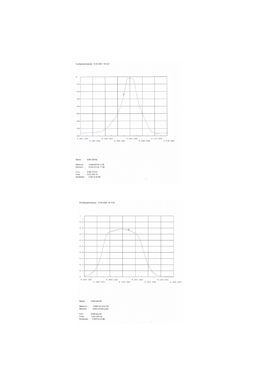
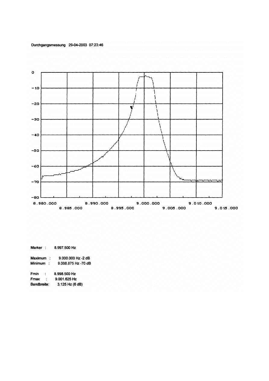
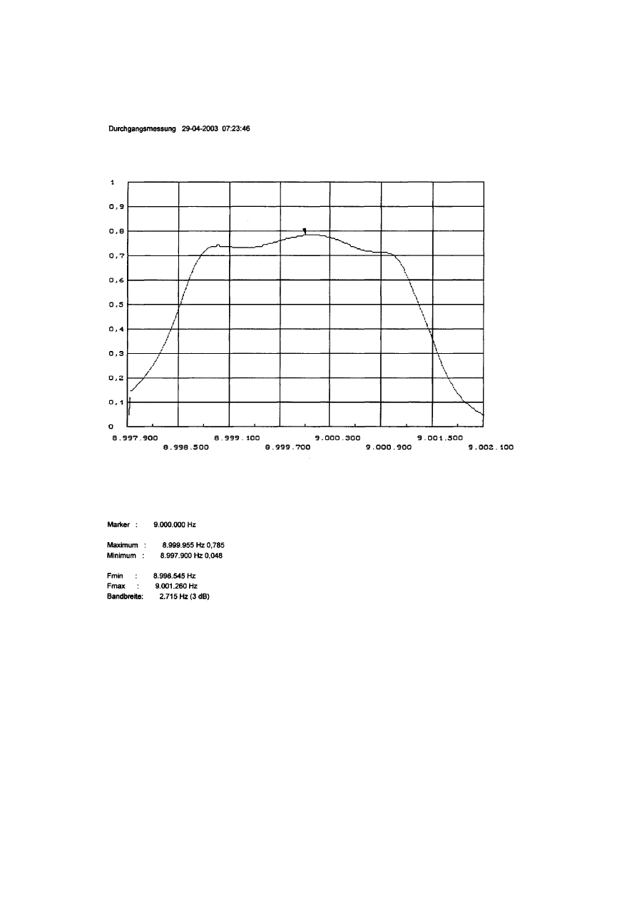
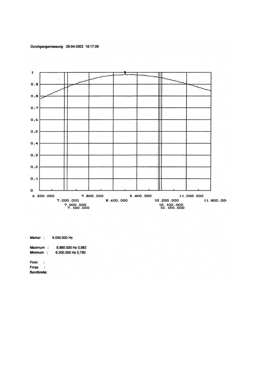
Measured response (OZ9FW) through the Combiner + Roofing filter + Combiner
Top picture log vertical scale – Bottom picture linear scale!
FRONT END 28072004.doc
3
1
3
2
1
5
FRONT END 28072004.doc
4
2
5
FRONT END 28072004.doc
5
B
A
B
A
FRONT END 28072004.doc
6
3
B
A
A B
5
FRONT END 28072004.doc
7
FRONT END 28072004.doc
8
FRONT END 28072004.doc
9
Wyszukiwarka
Podobne podstrony:
Front End Replacing Tie Rod Ends
Front End Alignment Basics
Front End Replacing Ball Joints
Front End Alignment Tests For
Front End
M39r Body Front End
FT 221 FT 225 Mutek Front end
BODY FRONT END SECTION 9R 14
2002 09 Creating Virtual Worlds with Pov Ray and the Right Front End
Front End
0 WIELKI ŚPIEWNIK WIELOGŁOSOWY front and end page
Japanese for busy people I (ch26 end)
ARTICLE SUSPENSION STRUT FRONT REPLACE INSTALL
więcej podobnych podstron