
SIMATIC Industrial PC SIMATIC Panel PC 477B
SIMATIC
Industrial PC
SIMATIC Panel PC 477B
Operating Instructions (Compact)
05/2007
A5E01023503-01
Safety Guidelines
Safety Guidelines
This manual contains notices you have to observe in order to ensure your personal safety, as well as to prevent
damage to property. The notices referring to your personal safety are highlighted in the manual by a safety alert
symbol, notices referring only to property damage have no safety alert symbol. These notices shown below are
graded according to the degree of danger.
Danger
indicates that death or severe personal injury will result if proper precautions are not taken.
Warning
indicates that death or severe personal injury may result if proper precautions are not taken.
Caution
with a safety alert symbol, indicates that minor personal injury can result if proper precautions are not taken.
Caution
without a safety alert symbol, indicates that property damage can result if proper precautions are not taken.
Notice
indicates that an unintended result or situation can occur if the corresponding information is not taken into
account.
If more than one degree of danger is present, the warning notice representing the highest degree of danger will
be used. A notice warning of injury to persons with a safety alert symbol may also include a warning relating to
property damage.
Qualified Personnel
The device/system may only be set up and used in conjunction with this documentation. Commissioning and
operation of a device/system may only be performed by qualified personnel. Within the context of the safety notes
in this documentation qualified persons are defined as persons who are authorized to commission, ground and
label devices, systems and circuits in accordance with established safety practices and standards.
Prescribed Usage
Note the following:
Warning
This device may only be used for the applications described in the catalog or the technical description and only
in connection with devices or components from other manufacturers which have been approved or
recommended by Siemens. Correct, reliable operation of the product requires proper transport, storage,
positioning and assembly as well as careful operation and maintenance.
Trademarks
All names identified by ® are registered trademarks of the Siemens AG. The remaining trademarks in this
publication may be trademarks whose use by third parties for their own purposes could violate the rights of the
owner.
Disclaimer of Liability
We have reviewed the contents of this publication to ensure consistency with the hardware and software
described. Since variance cannot be precluded entirely, we cannot guarantee full consistency. However, the
information in this publication is reviewed regularly and any necessary corrections are included in subsequent
editions.
Siemens AG
Automation and Drives
Postfach 48 48
90437 NÜRNBERG
GERMANY
A5E01023503-01
Ⓟ 05/2007
Copyright © Siemens AG 2007.
Technical data subject to change

SIMATIC Panel PC 477B
Operating Instructions (Compact), 05/2007, A5E01023503-01
3
Table of contents
1
Operating Instructions (compact)............................................................................................................... 5
1.1
Safety instructions..........................................................................................................................5
1.2
Product documentation ..................................................................................................................5
1.3
Unpacking and checking the delivery ............................................................................................6
1.4
Components of the Product ...........................................................................................................6
1.5
Device identification data ...............................................................................................................7
1.6
Accessories....................................................................................................................................7
1.7
Affixing Labeling Strips for Function Keys and Softkeys ...............................................................8
1.8
Installing/Mounting .......................................................................................................................12
1.8.1
Permitted mounting positions.......................................................................................................12
1.8.2
Preparing the mounting cut-out....................................................................................................13
1.8.3
Securing the Device with Clamps ................................................................................................15
1.8.4
Securing the Device with Screws.................................................................................................16
1.9
Connecting...................................................................................................................................18
1.9.1
Connection components ..............................................................................................................18
1.9.2
Connecting the 24 V DC power supply........................................................................................20
1.10
Commissioning.............................................................................................................................22
1.10.1 Commissioning Information .........................................................................................................22
1.10.2 Basic commissioning - initial startup............................................................................................22
1.10.3 Setting the Panel Type.................................................................................................................24
1.10.4 Device with key panel ..................................................................................................................25
1.10.4.1 Activating KeyTools .....................................................................................................................25
1.10.5 Device with touch screen.............................................................................................................26
1.10.5.1 Recalibrating the Touch Screen...................................................................................................26
1.10.5.2 Activating the Screen Keyboard ..................................................................................................27
1.11
Service and support .....................................................................................................................28

Table of contents
SIMATIC Panel PC 477B
4
Operating Instructions (Compact), 05/2007, A5E01023503-01

SIMATIC Panel PC 477B
Operating Instructions (Compact), 05/2007, A5E01023503-01
5
Operating Instructions (compact)
1
1.1
Safety instructions
Caution
In order to avoid substantial damage and for your own safety, note the safety instructions in
this documentation and in the operating instructions.
Warning
Function test while installing the device in machines or execute systems
Following the results of a risk analysis, additional protection equipment on the machine or
the system is necessary to avoid endangering persons. With this, especially the
programming, configuration and wiring of the inserted I/O modules have to be executed, in
accordance with the safety performance (SIL, PL or Cat.) identified by the necessary risk
analysis. The intended use of the device has to be ensured.
The correct use of the device has to be verified with a function test on the system. This test
can detect programming, configuration and wiring errors. The test results have to be
documented and, if necessary, entered into the relevant documents that verify safety.
1.2
Product documentation
Product documentation
The detailed operating instructions for Panel PC 477B is provided as a PDF file that is
available on the Documentation and Drivers CD or can be downloaded on the Internet under
the following address: http://support.automation.siemens.com
Operating Instructions (compact)
1.3 Unpacking and checking the delivery
SIMATIC Panel PC 477B
6
Operating Instructions (Compact), 05/2007, A5E01023503-01
1.3
Unpacking and checking the delivery
1. Please check the packaging material for transport damage upon delivery.
2. If any transport damage is present at the time of delivery, lodge a complaint at the
shipping company in charge. Have the shipper confirm the transport damage
immediately.
3. Unpack the device.
Notice
Lie the front side on a soft surface to avoid damaging the front panel USB port.
4. Keep the packaging material in case you have to transport the unit again.
Note
The packaging protects the device during transport and storage. Therefore, never
dispose of the original packaging material!
5. Please keep the enclosed documentation in a safe place. You will need the
documentation when you start up the device for the first time.
6. Check the contents of the package for completeness and transportation damage. Check
for completeness using the enclosed scope of delivery list.
7. Should the contents of the package be incomplete or damaged, please inform the
responsible supply service immediately and fax us the enclosed form "SIMATIC IPC/PG
quality control report".
Warning
Make sure that a damaged device is not installed nor put into operation.
8. Note the identification information (see chapter "Identification data of the device").
1.4
Components of the Product
Amount Designation
Description
1
SIMATIC Panel PC 477B
1
Documentation and Drivers CD Contains the documentation and the hardware drivers.
1
Operating Instructions
(compact)
SIMATIC Panel PC 477B
Printed copies in German and English of the SIMATIC Panel PC 477B
Operating Instructions (Compact).
Additional language versions (French, Spanish, Italian and Chinese simplified)
are provided as PDF files on the Documentation and Drivers CD.
6
Clamp
Mounting clamp for the SIMATIC Panel PC 477B.
1
DC power plug
Only supply variant with 24 V DC power supply.

Operating Instructions (compact)
1.5 Device identification data
SIMATIC Panel PC 477B
Operating Instructions (Compact), 05/2007, A5E01023503-01
7
1.5
Device identification data
Enter the identification data of the device into the table.
Serial number (on the type plate)
S VP ...
Order no. of the device
Microsoft Windows Product Key from the "Certificate of Authenticity" (COA).
Ethernet address 1:
Ethernet address 2:
BIOS Setup (F2 key) under Main > Hardware Options > Ethernet Address
1.6
Accessories
These accessories are not included in the product package.
Accessories
Order No.
PCI-104 / PC/104Plus expansion kit
6AG4070 - 0BA00 - 0XA0
512 MB Compact Flash card
6ES7648 - 2BF01 - 0XD0
1 GB Compact Flash card
6ES7648 - 2BF01 - 0XE0
2 GB Compact Flash card
6ES7648 - 2BF01 - 0XF0
SIMATIC USB-Flash Drive, USB 2.0, 512 MB
6ES7648 - 0DC20 - 0AA0
SIMATIC USB Flash Drive, USB 2.0, 1 GB
6ES7648 - 0DC30 - 0AA0
256 MB DDR2 SODIMM memory module
6ES7648-2AG20-0GA0
512 MB DDR2 SODIMM memory module
6ES7648-2AC30-0GA0
1 GB DDR2 SODIMM memory module
6ES7648-2AG40-0GA0
2 GB DDR2 667, SODIMM memory module
6ES7648 - 2AG50 - 0HA0
Screw mounting 19" device
6AV7672-8KE00-0AA0

Operating Instructions (compact)
1.7 Affixing Labeling Strips for Function Keys and Softkeys
SIMATIC Panel PC 477B
8
Operating Instructions (Compact), 05/2007, A5E01023503-01
1.7
Affixing Labeling Strips for Function Keys and Softkeys
Note
The following table applies only to devices with a key panel.
The control unit has two horizontal and two vertical keypads for the function keys and the
softkeys. Assign user specific functions to the keys as needed. You can mark these keys
with labeling strips. A4 films for creating the labeling strips are available as accessories.
Proceed as follows to affix the labeling strips:
Preparing the labeling strips
1. Label the DIN A4 film with a laser printer, for example using the printing templates
provided on the Documentation and Drivers CD.
2. Cut the labeling strips along the pre-printed lines.
Note
Do not insert handwritten labeling strips until the ink has dried.
Separating the control unit from the computer unit
Caution
Work on the open device may only be carried out by authorized and qualified personnel.
Within the warranty time, you are only allowed to install expansions for memory and
expansion card modules.
Caution
The device contains electronic components that can be destroyed by electrostatic charges.
You should therefore follow safety precautions when opening the device. Refer to the
(ESD) guidelines for handling electrostatic sensitive devices.
Tool required to separate the computer unit from the control unit: Torx T10 screwdriver
Operating Instructions (compact)
1.7 Affixing Labeling Strips for Function Keys and Softkeys
SIMATIC Panel PC 477B
Operating Instructions (Compact), 05/2007, A5E01023503-01
9
1. Disconnect the device from the power supply.
Warning
Unauthorized opening of the device may result in substantial damage to equipment or
endanger the user. Always disconnect the device from the power supply before opening
it.
2. Unplug all peripherals (mouse, keyboard, external monitor, for example) from the device.
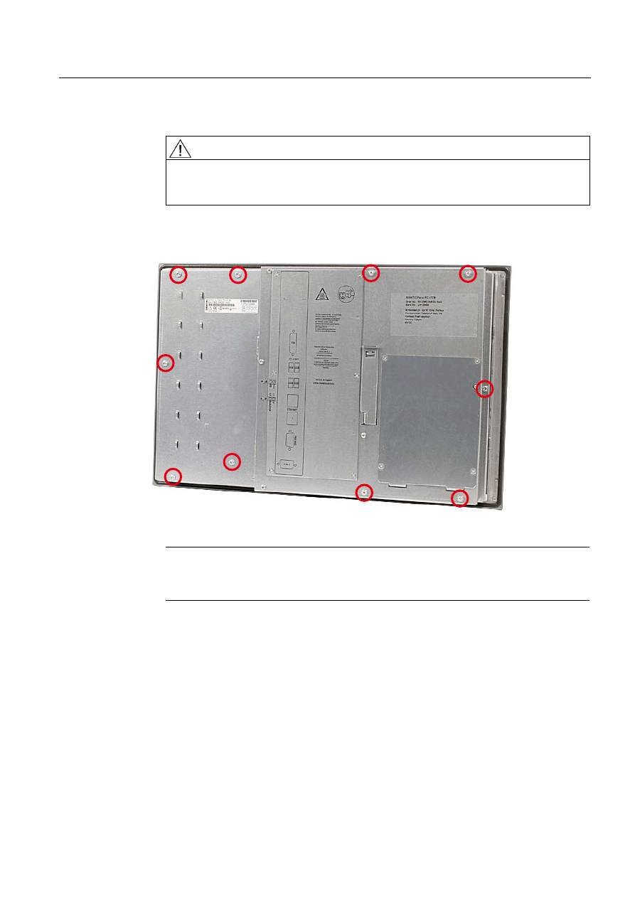
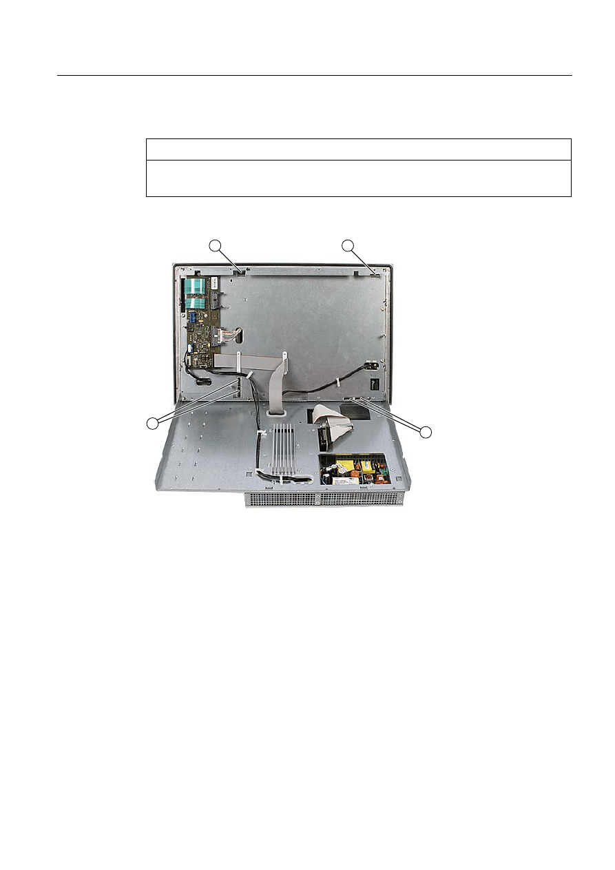
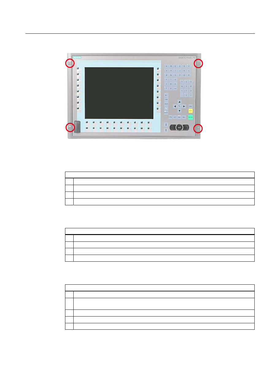
3. Loosen the indicated screws that secure the computer unit to the control unit.
Figure 1-1
Example 12" touch screen device
Note
Device variants
The number of screws to be screwed out varies depending on the device variants.
Operating Instructions (compact)
1.7 Affixing Labeling Strips for Function Keys and Softkeys
SIMATIC Panel PC 477B
10
Operating Instructions (Compact), 05/2007, A5E01023503-01
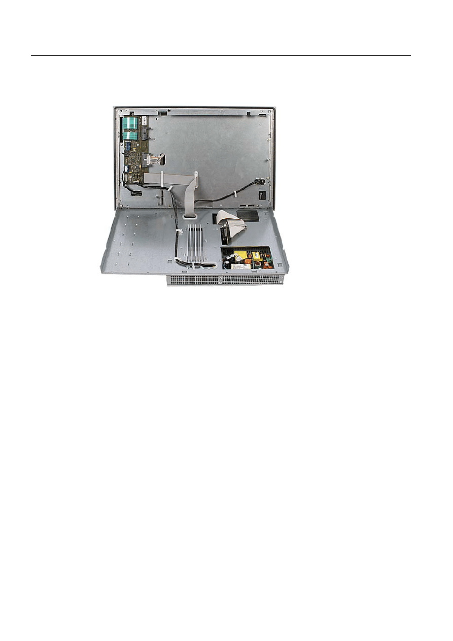
4. Fold out the computer unit along the articulated joint.
Figure 1-2
Example 12" touch screen device: Separating the computer unit from the control unit
Operating Instructions (compact)
1.7 Affixing Labeling Strips for Function Keys and Softkeys
SIMATIC Panel PC 477B
Operating Instructions (Compact), 05/2007, A5E01023503-01
11
Affixing the labeling strips
Notice
Risk of damage
Do not under any circumstances touch exposed components of the control unit.
Insert the labeling strips into the slots provided on the rear of the control unit.
Figure 1-3
Device rear with connections and slots for the labeling strips
1
Slots for long labeling strips, vertical keypads
2
Slots for short labeling strips, horizontal keypads
3
Slots for labeling strips, horizontal keypads
Screwing the computer unit onto the control unit
Mount the computer unit back onto the control unit using the screws that were removed
beforehand.
Operating Instructions (compact)
1.8 Installing/Mounting
SIMATIC Panel PC 477B
12
Operating Instructions (Compact), 05/2007, A5E01023503-01
1.8
Installing/Mounting
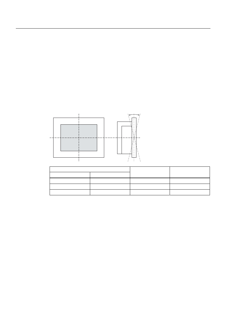
1.8.1
Permitted mounting positions
Mounting positions
Only vertical installation with two mounting directions of
up to +15° and -15° or up to +30° and -30° are permitted for the device.
With installed Compact Flash card
$
%
Temperature at the device
Rear
Front
Angle A
Angle B
5° - 50°C
Max. 40°C
15°
15°
5° - 45°C
5° - 45°C
15°
15°
5° - 40°C
5° - 40°C
30°
30°
Mechanical environmental conditions
● Vibration
– Operation, tested in accordance with DIN IEC 60068-2-6
10 to 58 Hz: 0.075 mm 58 to 200 Hz: 9.8 m/s2
– Storage/transport, tested according to IEC 60068-2-27, IEC 60068-2-29
50 m/s2, 30 ms,
250 m/s2, 6 ms,
Operating Instructions (compact)
1.8 Installing/Mounting
SIMATIC Panel PC 477B
Operating Instructions (Compact), 05/2007, A5E01023503-01
13
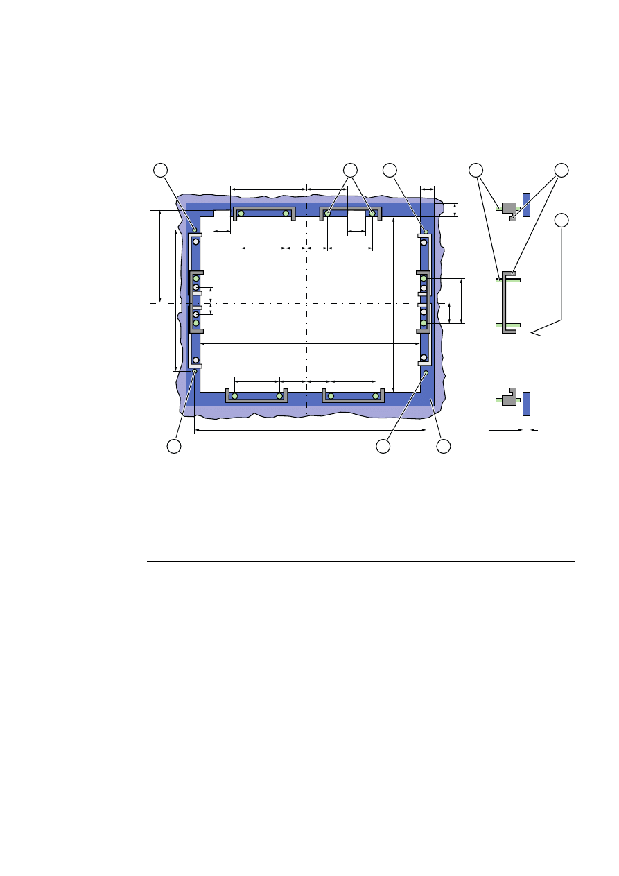
1.8.2
Preparing the mounting cut-out
The following illustration shows the dimensions for the mounting cut-out.
PP
/
/
/
/
6
6
/
/
6
6
/
/
/
/
/
$
6
/
/
6
6
/
$
Figure 1-4
Drill holes for the screws and pressure points for the clamp screws
(1) Drill hole for screw attachment
(4)
Clamp
(2) Pressure points for clamp
(5)
R
Z
120 in the seal area
(3) Setscrews
(6)
Seal area
Note
Mounting dimensions can be read from the dimension overview or they can be transferred to
the cabinet from the mounting template supplied.
Operating Instructions (compact)
1.8 Installing/Mounting
SIMATIC Panel PC 477B
14
Operating Instructions (Compact), 05/2007, A5E01023503-01
Table 1-1
Dimensions for the mounting cut-out in mm
Control
unit
L1
L2
L3
1)
L4
1)
L5
L6
2)
L7
2)
L8
2)
L9
2)
A1 A2 S1
S2
S3
S4
S5
3)
S6
3)
S7
3)
Tolerance
±1
+1
±0,2 ±0.2 ±0.5 ±0.5 ±0.5 ±0.5 +1
±1 ±1 ±1
±1
±1
±1
Key
panel
12" TFT
15" TFT
450
450
290
321
465
465
235
279
112
112
—
186
—
135
—
25
—
165
16
16
10
17
78
51
78
51
56
56
—
—
Touch
panel
12" TFT
15" TFT
19" TFT
368
450
450
290
290
380
—
465
465
—
235
235
112
112
112
—
—
—
—
—
—
—
—
—
—
—
—
16
16
16
10
10
10
19
81
46
35
81
46
56
56
—
—
—
33
1)
M6 thread or drill holes with a diameter of 7 mm
2)
Cut-outs for the shafts of the insert strips are only necessary for 15" key panels.
3)
Two clamps necessary for vertically securing clamps only for 19" touch panel fronts.
Preparing the mounting cut-out
Steps for preparing the mounting cut-out
1. Select a location suitable for mounting, taking into account the mounting position.
2. On the basis of the dimensions, check whether the required screw and pressure points on the
rear and the seal area are easily accessible after the completion of the mounting cut-out.
Otherwise the mounting cut-out is useless.
3. Complete the mounting cut-out in accordance with the dimensions.
Operating Instructions (compact)
1.8 Installing/Mounting
SIMATIC Panel PC 477B
Operating Instructions (Compact), 05/2007, A5E01023503-01
15
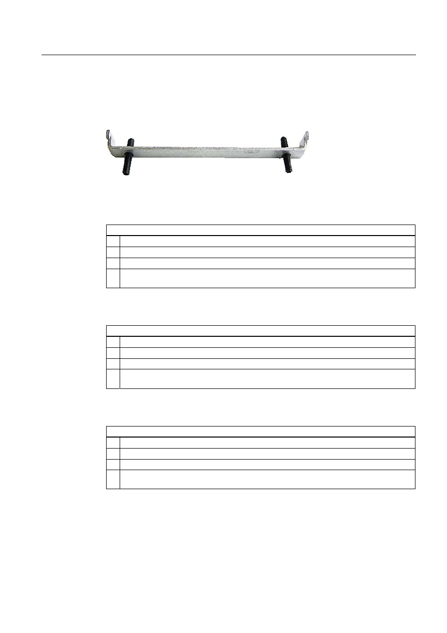
1.8.3
Securing the Device with Clamps
You require 6 clamps in order to mount the device. These are supplied with the device.
Required tool for fasting the clamps: Allen wrench 2.5 mm
Figure 1-5
Clamp assembly
Rack mounting
Steps for fastening the device with clamps
1. Follow the installation instructions.
2. Disconnect the device from the power supply.
3. Working from the front, insert the device into the 19" rack.
4. Fasten the control unit in the rack from the rear using the clamps. Tighten the setscrews to a
torque of 0.4-0.5 Nm.
Swivel arm mounting
Steps for fastening the device with clamps
1. Follow the installation instructions.
2. Disconnect the device from the power supply.
3. Working from the front, place the device onto the swivel arm.
4. Fasten the control unit on the swivel arm from the rear using the clamps. Tighten the setscrews
to a torque of 0.4-0.5 Nm.
Switchgear cabinet installation
Steps for fastening the device with clamps
1. Follow the installation instructions.
2. Disconnect the device from the power supply.
3. Working from the front, insert the device into the mounting cut-out.
4. Secure the control unit in the mounting cut-out from behind with the clamps, as shown in the
mounting cut-out in the dimensions. Tighten the setscrews to a torque of 0.4-0.5 Nm.
IP65 degree of protection
The IP65 degree of protection is only provided for a clamp mounting together with a ring
seal.

Operating Instructions (compact)
1.8 Installing/Mounting
SIMATIC Panel PC 477B
16
Operating Instructions (Compact), 05/2007, A5E01023503-01
Notice
Switchgear cabinet installation: Material strength at the mounting cut-out
Please ensure that the material strength at the mounting cut-out is a maximum of 6 mm.
Please follow the specifications for the dimensions in the "Preparing the mounting cut-out"
section.
The degree of protection can only be guaranteed when the following requirements are met:
1. The material strength at the mounting cut-out must be at least 2 mm.
2. The deviation from the plane of the mounting cut-out in relation to the external
dimensions for an installed HMI device is ≤ 0.5 mm.
1.8.4
Securing the Device with Screws
IP54 degree of protection
This degree of protection is ensured for screw mounting.
Notice
Switchgear cabinet installation: Material strength at the mounting cut-out
Please ensure that the material strength at the mounting cut-out is a maximum of 6 mm.
Please follow the specifications for the dimensions in the "Preparing the Mounting Cut-out"
section.
The degree of protection can only be guaranteed when the following requirements are met:
1. The material strength at the mounting cut-out must be at least 2 mm.
2. The deviation from the plane of the mounting cut-out in relation to the external
dimensions for an installed HMI device is ≤ 0.5 mm.
Note
Securing with screws is not possible with the 12" touch screen variant.
Required tool for fasting with screws: 7 mm drill
Notice
Only use the catalog-listed mounting material (order number 6AV7672-8KE00-0AA0) for
19" devices for screw mounting.
Notice
Risk of damage
Ensure that no metal cuttings enter the device when the holes are drilled. Cover the device
with film or when drilling, use removal by suction.
Operating Instructions (compact)
1.8 Installing/Mounting
SIMATIC Panel PC 477B
Operating Instructions (Compact), 05/2007, A5E01023503-01
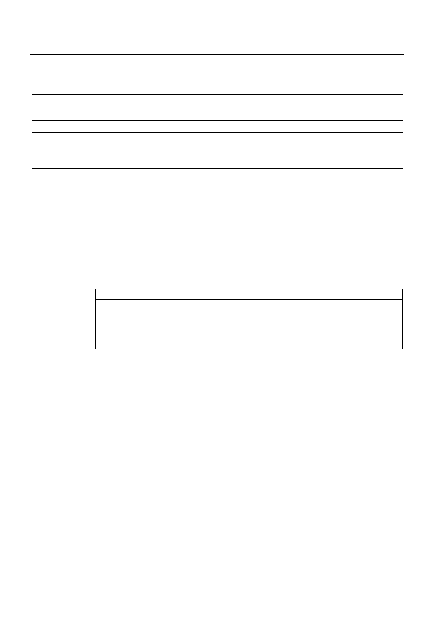
17
Figure 1-6
Designated location for holes on the control unit
Rack mounting
Steps for fastening the device with screws
1. Follow the installation instructions.
2. Carefully drill the respective holes in the control unit at the designed location from the rear.
3. Working from the front, insert the device into the 19" rack.
4. Secure the control unit by inserting suitable screws through the holes and attaching nuts.
Swivel arm mounting
Steps for fastening the device with screws
1. Follow the installation instructions.
2. Carefully drill the respective holes in the control unit at the designed location from the rear.
3. Working from the front, place the device onto the swivel arm.
4. Secure the control unit by inserting suitable screws through the holes and attaching nuts.
Switchgear cabinet installation
Steps for fastening the device with screws
1. Follow the installation instructions.
2. Drill suitable holes at the prepared installation cut-out in accordance with the specifications for L4
and L5, as shown at the dimensions in the mounting cut-out
3. Carefully drill the respective holes in the control unit at the designed location from the rear.
4. Working from the front, insert the device into the mounting cut-out.
5. Secure the control unit by inserting suitable screws through the holes and attaching nuts.
Operating Instructions (compact)
1.9 Connecting
SIMATIC Panel PC 477B
18
Operating Instructions (Compact), 05/2007, A5E01023503-01
1.9
Connecting
1.9.1
Connection components
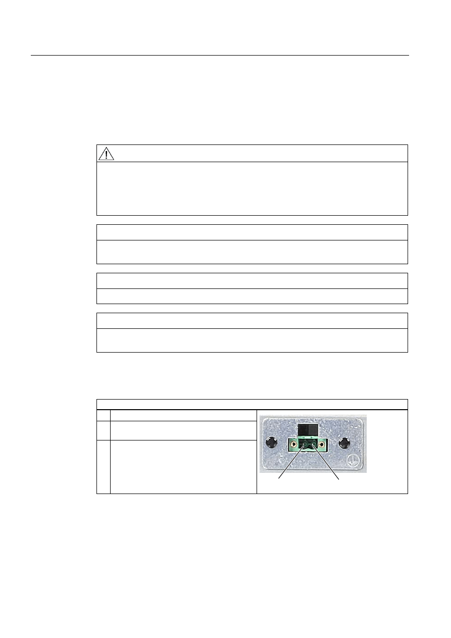
Connectors of control unit
Connector locations
Item Designation
Description
(1)
USB
1 connection USB 2.0 / 500 mA under sealed cover
Notice
Ensuring of protective class
When the sealed cover over the USB port is removed in order to connect a USB
component, the degree of protection for the device is no longer guaranteed.
Operating Instructions (compact)
1.9 Connecting
SIMATIC Panel PC 477B
Operating Instructions (Compact), 05/2007, A5E01023503-01
19
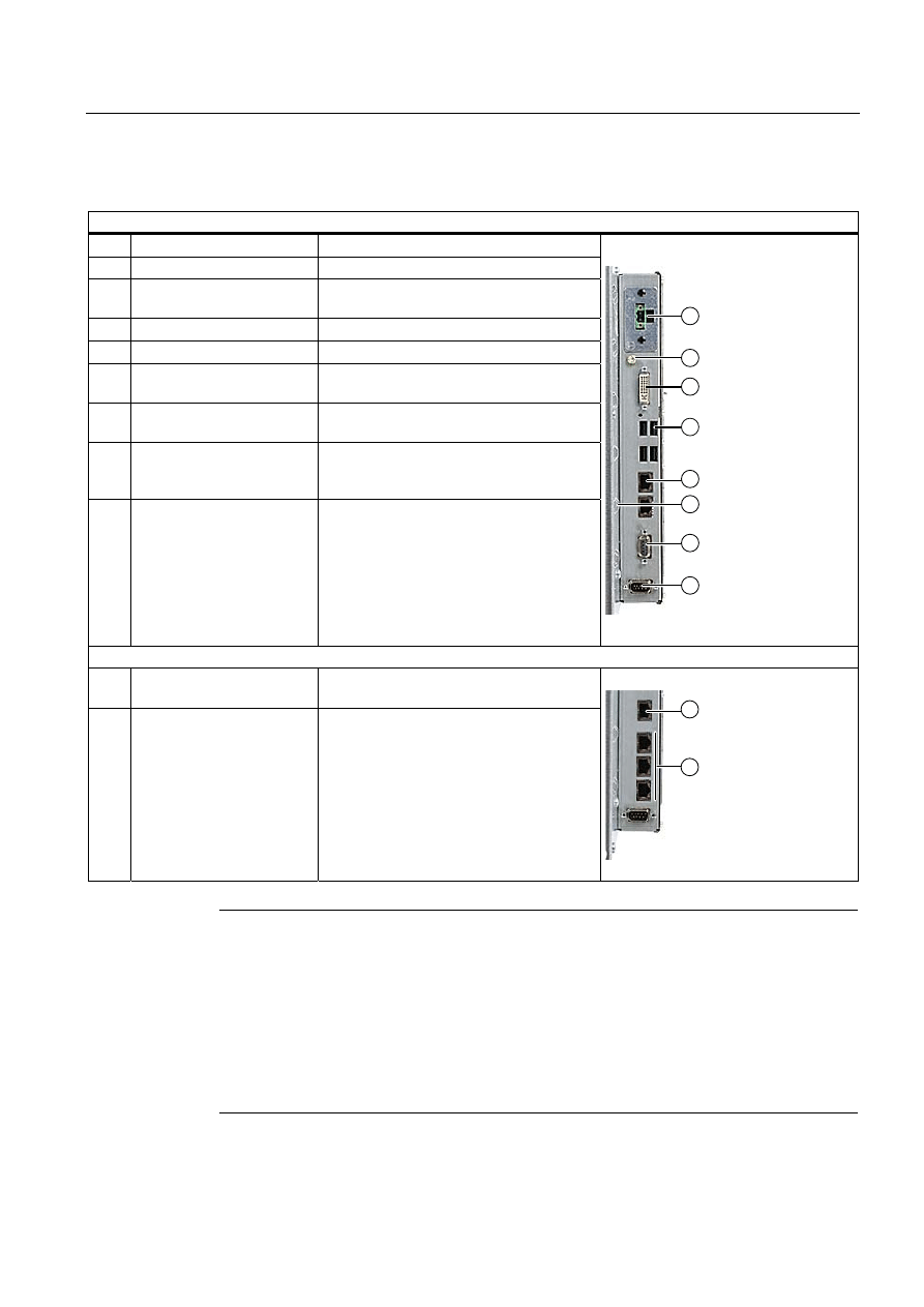
Connectors of computer unit
Connector locations
Item Designation
Description
(1)
24 V DC
Connection for a 24 V DC power supply
(2)
Protective conductor
Connection for low-resistance grounding
connection
(3)
DVI
DVI-I socket
(4)
USB
4 USB 2.0 connections / 500 mA
(5)
ETHERNET
2 RJ45 Ethernet connections for
10/100/1000 Mbps
(6)
Metal eyes
Eyes for connection strain relief via cable
ties
(7)
PROFIBUS DP/MPI
PROFIBUS-DP/MPI interface
(RS 485, electrically isolated),
9-pin Cannon socket
(8)
COM 1
Serial port 1 (RS232)
9-pin Cannon socket
Variants with PROFINET
(5)
ETHERNET
1 RJ45 Ethernet connection for
10/100/1000 Mbps
(7)
PROFINET
3 RJ45 Ethernet connections for 100 Mbps
Note
Use of USB devices
•
Wait at least 10 seconds between the unplugging and replugging of USB devices. This
also applies in particular to touch control in control units with touch screen panels.
•
When using standard USB peripherals, bear in mind that their EMC immunity level is
frequently designed for office applications only. However, only industry-standard devices
are allowed for industrial operation.
•
Peripherals are developed and marketed by individual vendors. The respective
manufacturers offer support for the peripherals. Moreover, the terms of liability of the
individual vendors or suppliers apply here.
Operating Instructions (compact)
1.9 Connecting
SIMATIC Panel PC 477B
20
Operating Instructions (Compact), 05/2007, A5E01023503-01
1.9.2
Connecting the 24 V DC power supply
Note before connecting
Note the following in order to operate the device safely and according to regulation:
Warning
The device is only allowed to be connected to a power supply VDC 24 according to NEC
class 2 or LPS (Limited Power Source).
Use the special plug supplied to connect the supply voltage.
The protective conductor on the device needs to be connected to the protective earth
conductor which is integrated in the cabinet.
Notice
The 24V DC power source must be adapted to the input data of the device (see technical
specifications).
Notice
The permitted cable cross-section for the 24 V DC connection is 0.75 mm
2
to 2,5 mm
2
.
Notice
If a Compact Flash card is used in the device, be sure that the card is properly installed
before you connect it.
Connecting 12" and 15" devices
Steps for connecting the device to the 24 V DC power supply
1. Switch off the 24 V DC power supply.
2. Connect the power supply using the plug
(included in the package).
3. Connect the PE conductor.
3LQ
0LQ
Power consumption
The power consumption at 24 V amounts to 70 W.
Operating Instructions (compact)
1.9 Connecting
SIMATIC Panel PC 477B
Operating Instructions (Compact), 05/2007, A5E01023503-01
21
Implementing the protective conductor
A low-impedance earth connection ensures that interference signals generated by external
power supply cables, signal cables or cables to the I/O modules are safely discharged to
earth.
Required tool for protective conductor: TORX T20 screwdriver.
Steps for connecting the PE conductor
1. Connect the protective conductor (M4
threads) (1) on the device (large surface,
large-area contact) with the protective earth
conductor of the cabinet or plant in which the
device is to be installed.
The minimum conductor cross-section may
not amount to less than 5 mm
2
.
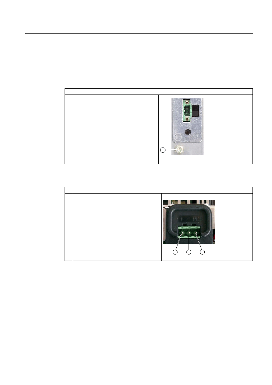
Connecting 19" devices
Steps for connecting the device to the 24 V DC power supply
1. Switch off the 24 V DC power source.
2. Connect the DC plug
(1) DC 24 V
(2) ground
(3) protective conductor
Power consumption
The power consumption at 24 V amounts to 90 W.

Operating Instructions (compact)
1.10 Commissioning
SIMATIC Panel PC 477B
22
Operating Instructions (Compact), 05/2007, A5E01023503-01
1.10
Commissioning
1.10.1
Commissioning Information
Note
Starting up Windows XP Embedded for the first time
System startup can take longer than usual for the initial commissioning. Only a blue screen
is displayed for several minutes.
Notice
Windows XP Embedded: Observe EWF Information
A configurable write filter (Enhanced Write Filter) is available under Windows XP
Embedded. Please observe the EWF rules during activation and use, since a data loss may
otherwise occur.
Note
Refer to the supplied Operating Instructions Compact (Software) to learn about the
procedure for installing the Compact Flash card with the Windows XP Embedded operating
system.
1.10.2
Basic commissioning - initial startup
Setting up the operating system
When the computer starts up for the first time, the Windows XP operating system on the
Compact Flash card or hard disk is configured automatically. Proceed as follows:
1. Connect the device to the 24 V DC power supply. The PC performs a self-test (POST).
During the self-test, this message appears:
Press <F2> to enter SETUP or <ESC> to display the boot menu
2. Wait until this message is cleared, then follow the instructions on the screen.
Notice
The device may not be switched off at any time during the installation process.
Do not change the default BIOS settings, otherwise the operating system setup may
become corrupted.

Operating Instructions (compact)
1.10 Commissioning
SIMATIC Panel PC 477B
Operating Instructions (Compact), 05/2007, A5E01023503-01
23
3. Restart
After you have entered all the necessary information and the operating system is
configured,
you are prompted to restart the system. Acknowledge this prompt with Yes.
Note
System startup can take longer than usual for the basic commissioning. A blue screen is
displayed for several minutes.
Note
Errors and warnings can be displayed in the status bar, with the first and second switch
on of the initial commissioning or after a restore procedure This will have no effect on the
device functions.
When you switch on the PC now, the user interface of the Windows XP Embedded operating
system is automatically opened when the startup routine is completed.
Note
To prevent data loss, it is advisable to create an image of your system partition after basic
commissioning.
Switching off the Device
When you work with Windows XP Embedded, always shut down the PC with the command
Start > Shut Down.
Note
The Enhanced Write Filter should be enabled following the installation of Windows XP
Embedded on a Compact Flash card. The device can then be switched off by disconnecting
the power supply.
Operating Instructions (compact)
1.10 Commissioning
SIMATIC Panel PC 477B
24
Operating Instructions (Compact), 05/2007, A5E01023503-01
1.10.3
Setting the Panel Type
Once the device has rebooted, several dialogs appear on the screen. Drivers and
applications can be installed from these dialogs.
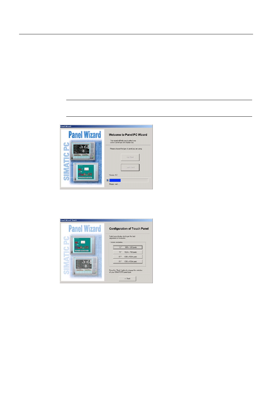
Setting the panel type
1. In the "Panel Wizard" dialog, click the type of panel that corresponds to your device.
Note
The devices with touch panel require a USB mouse or USB keyboard for commissioning.
Figure 1-7
Panel Wizard, Welcome dialog
2. In the "Panel Wizard Touch" dialog, click on the screen size that corresponds to your
device. The screen resolution is set correspondingly for the device.
Figure 1-8
Touch panel; selection of the screen size
The next step only applies to control units with touch screen panels.
Once the screen size is selected, the wizard will search for new hardware, the touch
controller. The Panel Wizard closes and the Touch Base calibration appears. Carry out
the following steps carefully.
Operating Instructions (compact)
1.10 Commissioning
SIMATIC Panel PC 477B
Operating Instructions (Compact), 05/2007, A5E01023503-01
25
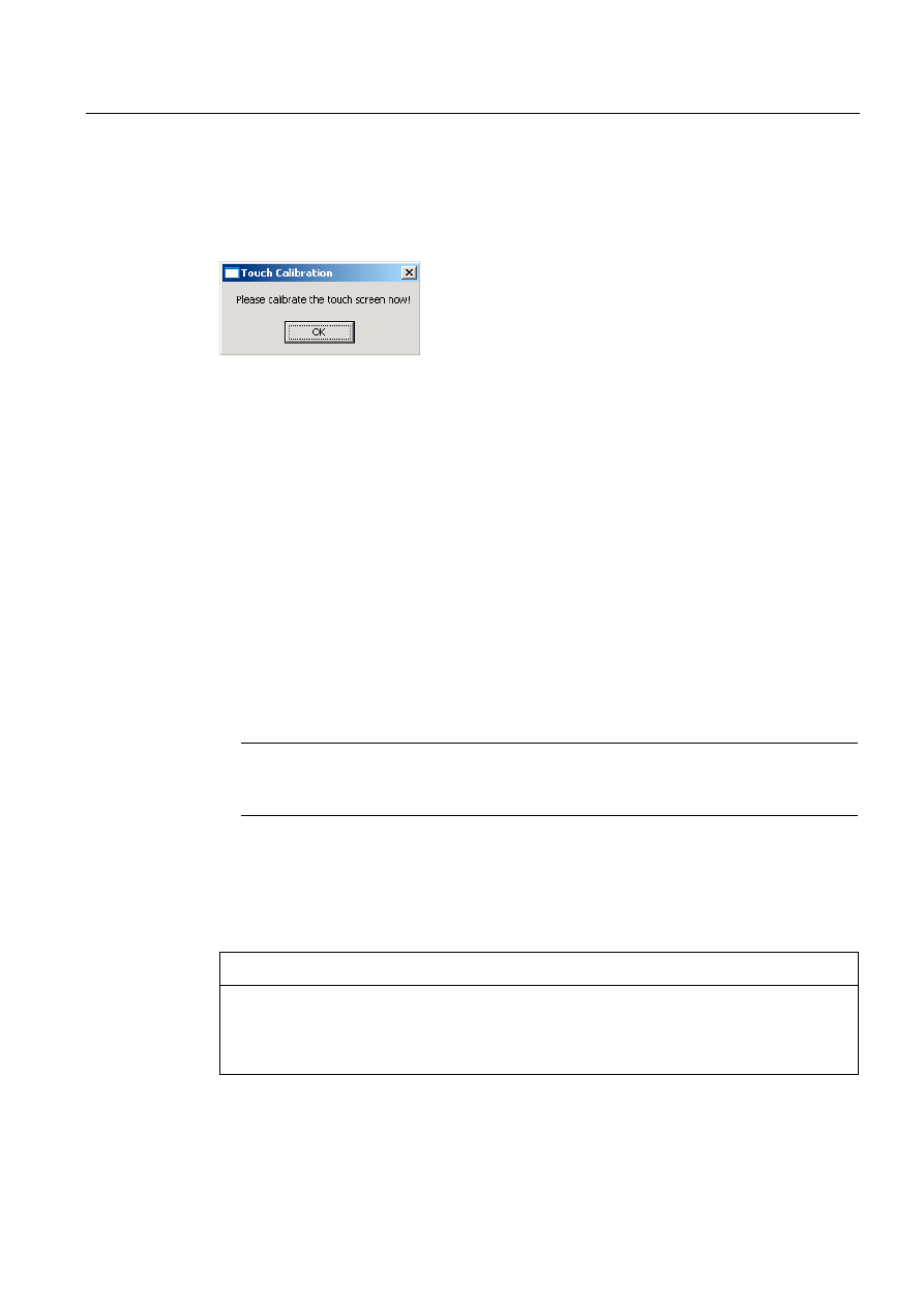
Touch screen calibration
After concluding the "Panel Wizard" dialog, the touch controller is installed.
1. Calibrate the touch screen.
Figure 1-9
Start touch screen calibration
2. Confirm with "OK".
1.10.4
Device with key panel
1.10.4.1 Activating KeyTools
SIMATIC KeyTools is one selection of the applications for SIMATIC Panel PC. These
applications allow you to adapt key codes that are sent by the key panel of the control unit.
SIMATIC KeyTools consists of the following applications:
● Key code table: Loading and editing of key code tables.
● WinCC hotkey function: WinCC hotkey function activation und deactivation.
● Security features: Lock function that prevents two function keys from being activated
simultaneously. This prevents incorrect operations and undefined states of the application
program.
Note
For a detailed description of the SIMATIC KeyTools, refer to the help menu and the
application description on the Documentation & Drivers DVD.
Opening Keytools
1. Open Keytools with the command Start > Settings > Control Panel > SIMATIC KeyTools.
2. Select the desired application and follow the instructions on the screen.
Notice
Malfunctions of the user software
For security reasons always use the "Security features". If you deactivate it nevertheless,
serious malfunctions of the user software may occur when the additional function keys and
softkeys F13 to S16 are used or if own key code tables are used.
Operating Instructions (compact)
1.10 Commissioning
SIMATIC Panel PC 477B
26
Operating Instructions (Compact), 05/2007, A5E01023503-01
1.10.5
Device with touch screen
1.10.5.1 Recalibrating the Touch Screen
If the touch screen does not react as expected when touched, repeat the calibration.
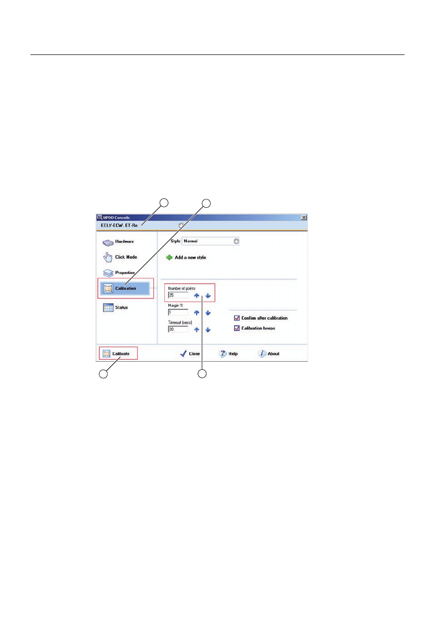
Procedure
1. Select "Start > Programs > UPDD > Settings".
The "UPDD Console" dialog box opens.
Figure 1-10 Point calibration
2. Select the screen (1) you wish to calibrate.
3. Click on "Calibration" (2).
4. Activate "25-point calibration" (3).
5. Click on "Calibrate" (4).
The calibration mask is output on the selected display.
6. Touch the blue arrow.
The input is confirmed by a tick, and the next arrow is displayed.
7. Confirm all input prompts (arrows, or crosses in the center) until the complete screen has
been calibrated.
Operating Instructions (compact)
1.10 Commissioning
SIMATIC Panel PC 477B
Operating Instructions (Compact), 05/2007, A5E01023503-01
27
Warning
Faulty operation
If you touch the touch screen while configuring it or if the screen saver is active, the
SIMATIC process visualization software, e.g. ProTool/Pro, will carry out the functions
which happen to be behind it.
Caution
Only touch one point on the touch screen and not several points at one time. You may
otherwise trigger unintended reactions.
Do not touch the screen in the following situations:
- During the booting process
- When plugging or unplugging USB components
- While Scandisk is running
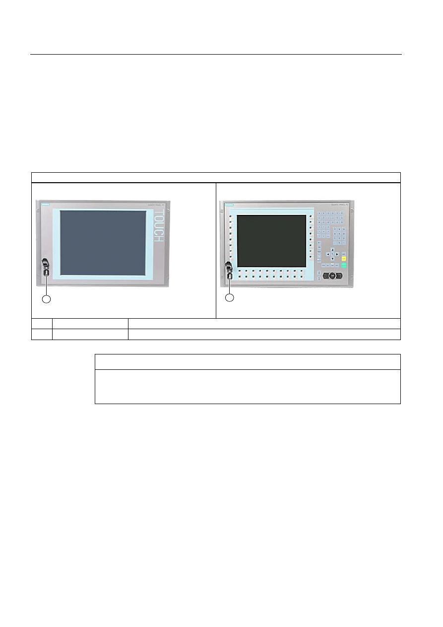
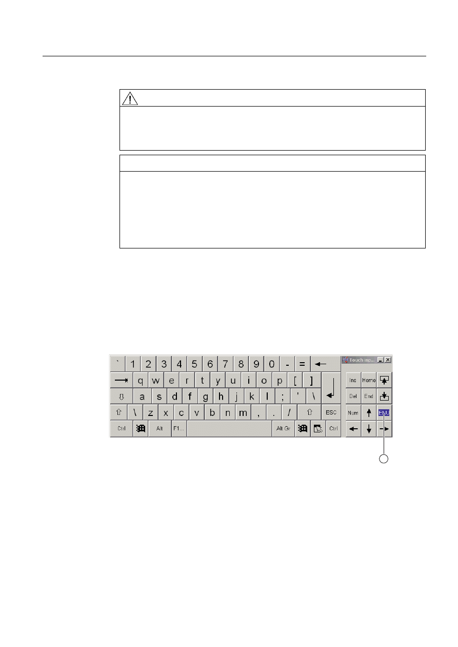
1.10.5.2 Activating the Screen Keyboard
You can operate the device by means of a virtual screen keyboard. You can use it to enter
the characters directly on the touch screen or with the mouse.
Starting Touch Input
Start the "Touch Input" application on the desktop. The screen keyboard is displayed.
(1) Button for language selection: German, English, Italian, Spanish, French

Operating Instructions (compact)
1.11 Service and support
SIMATIC Panel PC 477B
28
Operating Instructions (Compact), 05/2007, A5E01023503-01
1.11
Service and support
Local information
If you have questions about the products described in this document, you can find help at:
http://www.siemens.com/automation/partner
Technical documentation for SIMATIC products
Further documentation for SIMATIC products and systems can be found at:
http://www.siemens.de/simatic-tech-doku-portal
Easy shopping with the A&D Mall
Catalog & online ordering system http://www.siemens.com/automation/mall
Training
All the training options are listed at: http://www.siemens.com/sitrain
Find a contact at: Phone: +49(911) 895-3200
Technical support
Tel +49 180 5050 222
Fax +49 180 5050 223
http://www.siemens.com/automation/service
You will find support request web form at:
http://www.siemens.de/automation/support-request
When you contact the customer support, please have the following information for the
technician on hand:
● BIOS version
● Order No. (MLFB) of the device
● Installed additional software
● Installed additional hardware
Online support
Information about the product, Support and Service, right through to the Technical Forum,
can be found at: http://www.siemens.com/automation/service&partner
After-sales information system for SIMATIC PC / PG
Information about contacts, drivers, and BIOS updates, FAQs and Customer Support can be
found at: http://www.siemens.com/asis
Document Outline
- SIMATIC Panel PC 477B
- Table of contents
- 1 Operating Instructions (compact)
- 1.1 Safety instructions
- 1.2 Product documentation
- 1.3 Unpacking and checking the delivery
- 1.4 Components of the Product
- 1.5 Device identification data
- 1.6 Accessories
- 1.7 Affixing Labeling Strips for Function Keys and Softkeys
- 1.8 Installing/Mounting
- 1.9 Connecting
- 1.10 Commissioning
- 1.11 Service and support
Wyszukiwarka
Podobne podstrony:
opic panel pc 677b 05 2007 en
opic panel pc 577b 11 2007 en
opic panel pc 477b software 05 2007 en
manual pc diagmonitor 02 2007 en
Rozp MG z 4 05 2007 szczeg warun funkc syst el en
overview simatic controllers 04 2007 en plc
cz16 05 2007
IIKolokwium25.05. 2007, Nieorganiczna, chemia2, Arkusze powtórzeniowe, Pobieranie1, studia 1.2, test
bm wt 13 15 g1 se2 sp 2 c3 22 05 2007
Biochemia - exam stoma - 30.05.2007, Prywatne, biochemia, biochemia 1, biochemia
materiałożnawstwo 9 - 08.05.2007, Materiałoznawstwo - wykłady
Hakin9 25 (05 2007) PL
LISTA AUT SEO PERFECT dn 22 05 2007
LISTA AUT SEO PERFECT dn 24 05 2007
scenariusz 05 2007 juz czas na wiosne, Praca, Scenariusze
overview sirius position switches 2007 en
AM1 k1p) 05 2007 ITN
Materiały na kolos 08.05.2007, Zarządzanie i inżynieria produkcji, Semestr 2, Materiałoznawstwo, Mat
więcej podobnych podstron