
DESCRIPTION AND OPERATING INSTRUCTIONS
FOR THE DUPLEX FILTER
Contents:
1.
Type sheet
2.
Spare parts drawing and spare parts list
3.
Description and Operating Instructions for the duplex filter
4.
Description and Operating Instructions for the filter element cleaning
5.
Data Sheet for the Differential Pressure Indicator (to order)
6.
Spare parts drawing for the Differential Pressure Indicator (to order)
BOLL & KIRCH assumes no liability for any mistakes by any misuse of the product.
We reserve the right to change this description without any prior notice!
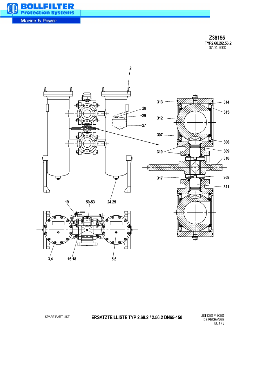
E R S A T Z T E I L L I S T E T Y P 2 . 6 8 . 2 / 2 . 5 6 . 2
SPARE PART LIST LISTE DES PIECES DE RECHANGE
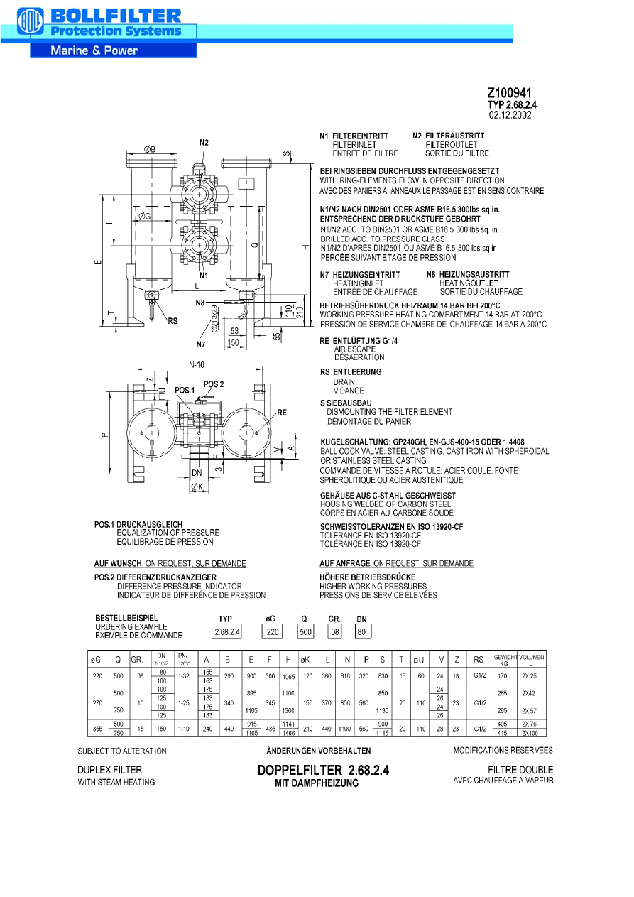
Typenschlüssel:
2.68.2
=
Doppelfilter
duplex filter
filtre double
G
=
Gehäusedurchmesser
cabin diameter
diamétre du corps
Q
=
Filtereinsatzlänge
length of the filter element
longueur du panier
DN
=
Anschlußflansche
connection flanges
brides désirées
Pos.
Nr.
Bezeichnung
designation
désignation
G 220
Q 500
Stück
parts
pièce
G 270
Q 500/750
Stück
parts
pièce
G 355
Q 500/750
Stück
parts
pièce
2
O-Ring
(Viton)
O-Ring
O-Ring
(Perbunan)
3030071
3040016
2
3030173
3040018
2
3030073
3040114
2
3
Stiftschraube
Stud bolt
Vis
2009088
24
2009088
24
2000007
24
4
Sechskantmutter
Nut
Ecrou
2100007
24
2100007
24
2100007
24
5
Dichtung
Gasket
Joint
3270002
2
3270002
2
3270002
2
6
Verschlussschraube
Screw Plug
Bouchon
2002885
2
2002885
2
2002885
2
16
Gewindebolzen
Stud bolt
boulon Filete
Z37736
10
Z37737
10
Z38017
10
18
Sechskantmutter
Nut
Ecrou
2100008
20
2100009
20
2101727
20
19
Kugelhahn
Ball valve
vannes a boisseau
G3/8
1
G3/8
1
G3/8
1
24
Dichtung
Gasket
Joint
3270004
2
3270006
2
3270006
2
25
Verschlussschraube
Screw Plug
Bouchon
2000189
2
2000191
2
2000191
2
27
Siebeinsatz
Filter element
Element filtrant
Fabr.Nr.
Filtertyp
Fabr.No.
Filtertype
Fabr.No.
Type de Filtre
28
Anker
Bolt
vis
WN 5.5.83
2
WN 5.1.90
WN 5.1.94
2
WN 5.1.90
WN 5.1.94
2
29
Sechskantmutter
Nut
Ecrou
2100033
2
2100035
2
2100035
2
50
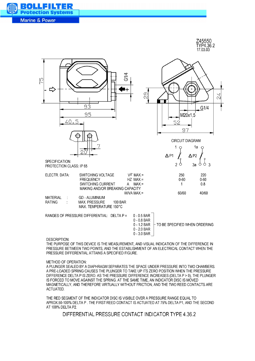
Differenzdruckanzeiger
different. press. indicator
press. diff. indicator
Typ
Druck
Type
Pressure
Type
Pression
51
Zylinderschraube
screw
vis
2000122
2
2000122
2
2000122
2
52
Sechskantmutter
Nut
Ecrou
2100003
2
2100003
2
2100003
2
53
Federring
Spring Washer
anne au ressant
2209799
2
2209799
2
2209799
2
Pos.
Nr.
Bezeichnung
designation
désignation
G 160
Q 500/750
Stück
parts
pièce
G 270
Q 500/750
Stück
parts
pièce
G 355
Q 500/750
Stück
parts
pièce
3-Wege-Kugelhahnschaltung
3-Wayball-Type Directional Valve
Combination
Commande de vitesse à rotule à
trois voies
08
10
15
306
Trägerring
Carrier Spacing
Anneau
Z38976
4
Z39165
4
Z39318
4
307
*
Kugeldichtring
Gasket
Anneau
Z38981
4
Z39166
4
Z39321
4
308
Mutter
Nut
Ecrou
Z38978
2
Z38978
2
Z39322
2
309
*
O-Ring
(Viton)
O-Ring
O-Ring
(Perbunan)
3030059
3043013
4
3030059
3043013
4
3038126
3040116
4
310
*
Dichtscheibe
Gasket
Anneau
Z38980
4
Z38980
4
Z39323
4
311
Spindel
Spindle
Axe
Z38975
2
Z39164
2
Z39317
2
312
Kugel
Ball
Boule
Z38996
2
Z39167
2
Z39319
2
313
*
O-Ring
(Viton)
O-Ring
O-Ring
(Perbunan)
3030762
3040762
4
3038313
3040015
4
3038825
3041700
4
314
*
O-Ring
(Viton)
O-Ring
O-Ring
(Perbunan)
3030036
3040012
4
3030038
3040014
4
3035892
3040017
4
315
Tellerfeder
Belleville spring washer
ressort a disque
Z38982
4
Z39163
4
Z39326
4
316
Sterngriff
switch star
manoeuvre
Z38983
1
Z38983
1
Z39324
1
317
Sicherungsblech
Securing Plate
Bague de frein pour arbres
Z38977
2
Z38977
2
Z39325
2
* )
Gekennzeichnete Positionen nur als Ersatzteilpaket lieferbar !
Marked items only available as spares package !
Les positions marquèes sont livrable uniquement en paquet !
INSTALLATION AND OPERATING INSTRUCTIONS FOR
BOLL DUPLEX FILTERS
1.
Description
Duplex filters which can be changed over consist of two filter housings operated in
parallel by a two-stage change-over device. The filter housings are designed to
meet the current regulations for a particular pressure range, the filter elements are
provided with an appropriate safety factor for the differential pressures indicated on
the filter nameplates. The maximum differential pressure for filter meshes is 0.8 bar,
for micro-cartridges 2 bar.
Duplex filters are used in cases where the contaminated filter elements have to be
regenerated without interrupting the filtration process.
The change-over devices, i.e. cylindrical plugs, ball valves or double-stage change-
over valves, permit change-over without pressure shocks. Owing to the design of
the change-over device it is not possible for both filter chambers to be switched off
at the same time.
2.
Installation
When the filter is attached to its foundation, the filter housing must be free from
strain. The same applies to the connected piping. The connections for the inlet and
outlet depend on the strainer element used (see works standard WN 211). Pay
attention to the arrow marked on the housing.
Heated filters with shut-off devices:
- Special equipment needed for heatable filters -
Heating of the filter serves to offset the heating loss at the filter during the filtration process
or before start-up of the plant to heat the liquid in the filter.
According to the AD Information Sheets, the filter housings
are only rated for internal overpressure. Additional external
forces and moments at the connection flanges of the filter are
to be avoided (possibly support feed lines).
a) Steam-heated
filters:
Safety valves for the filter chamber set to operate at the
relief pressure which is 10 % above the max. admissible
operating pressure of the filter housing.
b)
Electrically heated filters:
Thermostats which cut off the power supply to the
heating element at a max. admissible temperature of
150 °C in the filter chamber and one safety valve per
filter pot.
3.
Start-up
3.1 Pressure filters (> 0.1 bar pressure in the filter)
Set the change-over device to the mid-position, both chambers in service, pressure
equalising cock open.
Open air vents of both chambers (with venting screws only about 1 turn).
Start plant up slowly.
Close air vents when the air has escaped and the liquid has started to emerge.
Isolate one filter chamber by operating the change-over device, leave the pressure
equalising cock open; while one of the filter chambers is being used for filtering, the
isolated chamber is on stand-by until the admissible differential pressure has built up
as a result of clogging.
At a differential pressure of 0.8 bar in filter meshes or 2 bar in micro-cartridge filters
change over to the clean filter chamber as follows:
Cleaning
• Check that the pressure equalising cock is open and whether the stand-by
chamber is full by briefly opening the air vents.
• Change over.
• Close pressure equalising cock.
• Open the air vent on the isolated filter; this releases the liquid pressure and it is
then possible to check whether the change-over device has cut off the flow to the
filter chamber.
In contrast to the change-over and ball valve devices, complete sealing is not
possible with the plug-type system; by opening the sludge outlet, liquid leaking
during the cleaning process can be drained off.
• Remove the housing cover from the isolated filter chamber.
• Drain liquid down to the strainer base in the case of basket strainers; drain filter
housing completely in the case of mantle strainers, cartridge strainers and micro-
cartridges.
• Remove the filter element vertically upwards.
It is imperative for the pressure equalising cock to only
remain closed in the cleaning phase so that there is no
inadmissible pressure build-up through the thermal
expansion of the medium in the isolated chamber.
In smaller duplex filters without pressure compensation the
heat expansion of the medium is so low that there is no
risk to the components.
• Clean filter element (see operating instructions "Strainer cleaning"); renew
disposable elements and install them in the filter.
• Before mounting the cover, check that the seal is in perfect condition and seated
properly.
It is imperative to renew seals which have become hardened and deformed.
Screw cover on, the air vent remains open.
Open pressure equalising cock or, if not installed, set change-over device to mid
position until the air has been vented.
• Close air vent. This filter is now on stand-by.
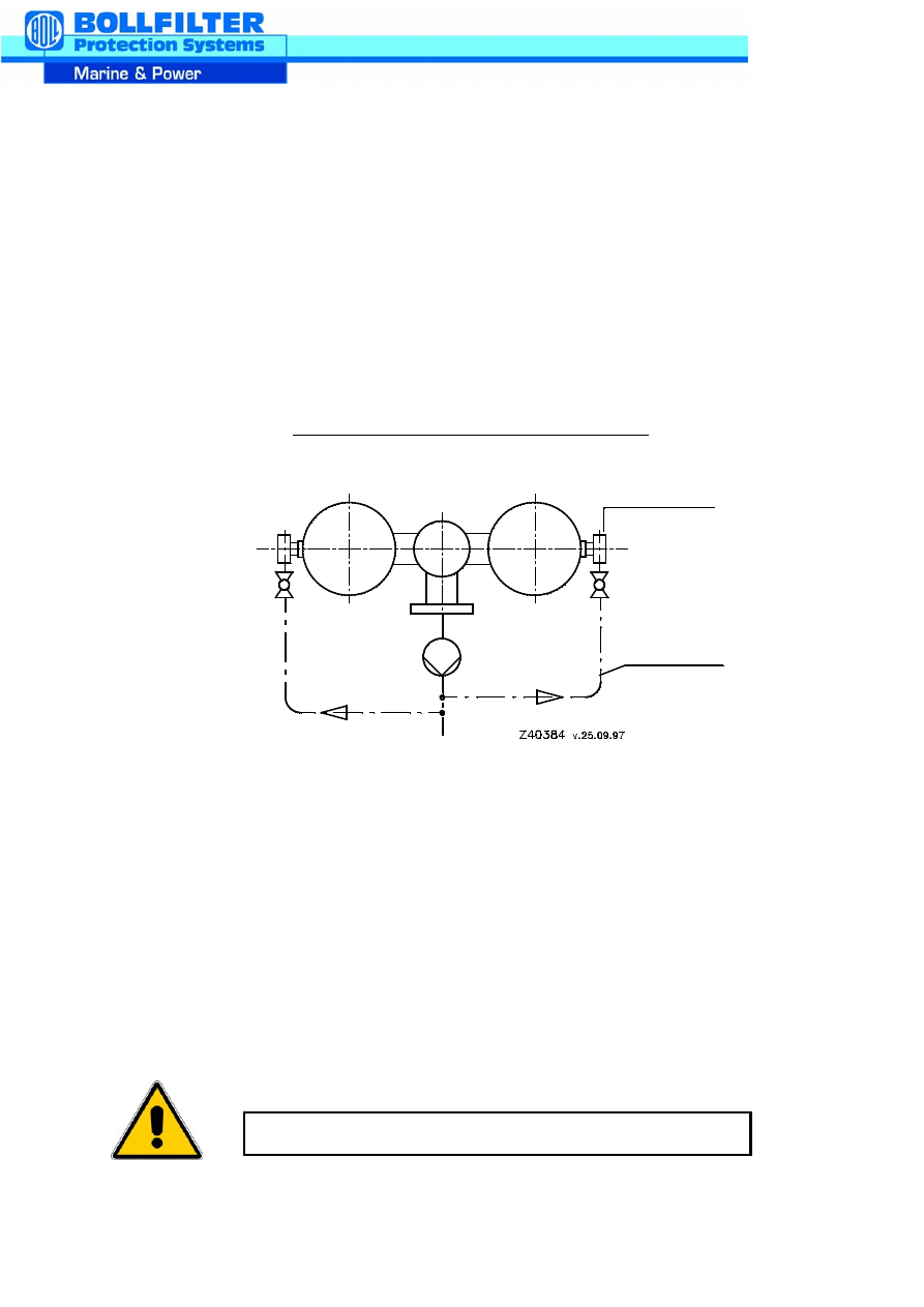
3.2
Suction filters (< 0.1 bar pressure in filter)
Recommended container filling for suction filters
drain
filling line
• Fill and vent both filter halves.
• Isolate one of the filters with the change-over device, close pressure equalising
cock.
• Start up the plant. While one filter chamber is being used for filtration, the isolated
chamber is on stand-by. When the differential pressure across the filter reaches
the maximum allowed by the pump suction head, a change-over to the other filter
half must be made.
• Open pressure equalising cock.
• Change over.
• Close pressure equalising cock.
• Open air vent on the isolated filter half.
Air may be drawn in if the level drops.
• Dismantle the housing cover from the isolated filter half.
• Drain liquid down to the strainer base.
• Remove filter element vertically upwards.
• Clean filter element (see operating instructions "Strainer cleaning"). Renew
disposable elements and install in the filter.
• Fill filter housing (see Fig.).
• Before mounting the cover, check that the seal is in perfect condition and seated
properly.
It is imperative to renew seals which have become hardened and deformed.
Close air vent.
• The cleaned filter half is ready on stand-by. This procedure is to be repeated from
section as and when required.
4.
Servicing:
Servicing of the duplex filter comprises checking and, if necessary, renew the
seals and filter elements. If the filter is provided with rust-inhibiting paint, touch up or
repaint as and when required.
When filtering cooling water or media which may cause sedimentation on the
change-over device, it is advisable to activate the change-over device as often as
possible and at regular intervals in order to prevent clogging.
BOLL & KIRCH assumes no liability for any mistakes by any misuse of the product.
We reserve the right to change this description without any prior notice!
It is not permitted to fill the filter against the
indicated flow direction of the filter elements.
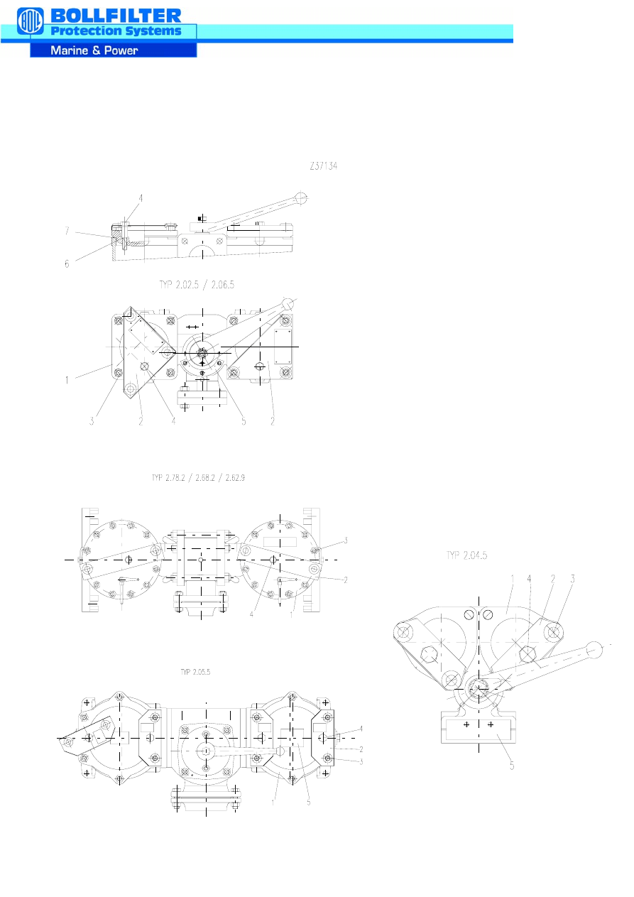
DESCRIPTION AND OPERATING INSTRUCTIONS
FOR 3-WAY BALL-TYPE DIRECTIONAL VALVE COMBINATION
DN 80, DN 100 AND DN 150
1.
General
All assembly work must always be performed only when the equipment is
depressurised and drained.
The company's safety regulations and the accident prevention regulations
must be observed when working on ball valves.
For depressurising and emptying duplex filters, refer to the operating in-
structions 'Duplex filters' or the operating instructions for 2.78.2 and 2.58.2.
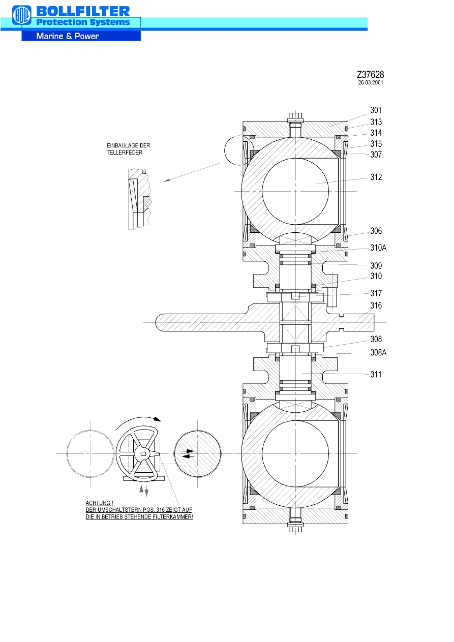
See drawing Z 37628
2.
Dismantling of the upper ball valve
2.1
The indicator of the star wheel (16) points to one filter chamber.
2.2
Remove pressure equalising cock.
2.3
Undo all the bolts of the flange connections on one filter bowl. Remove filter bowl
after undoing the anchor bolts.
2.4
Unscrew upper ball valve from the pipe connection and filter bowl.
2.5
Pull the upper ball valve out after removing the bolts.
2.6
The lower ball valve and star wheel (16) with the position indicator remain on the
duplex filter.
2.7
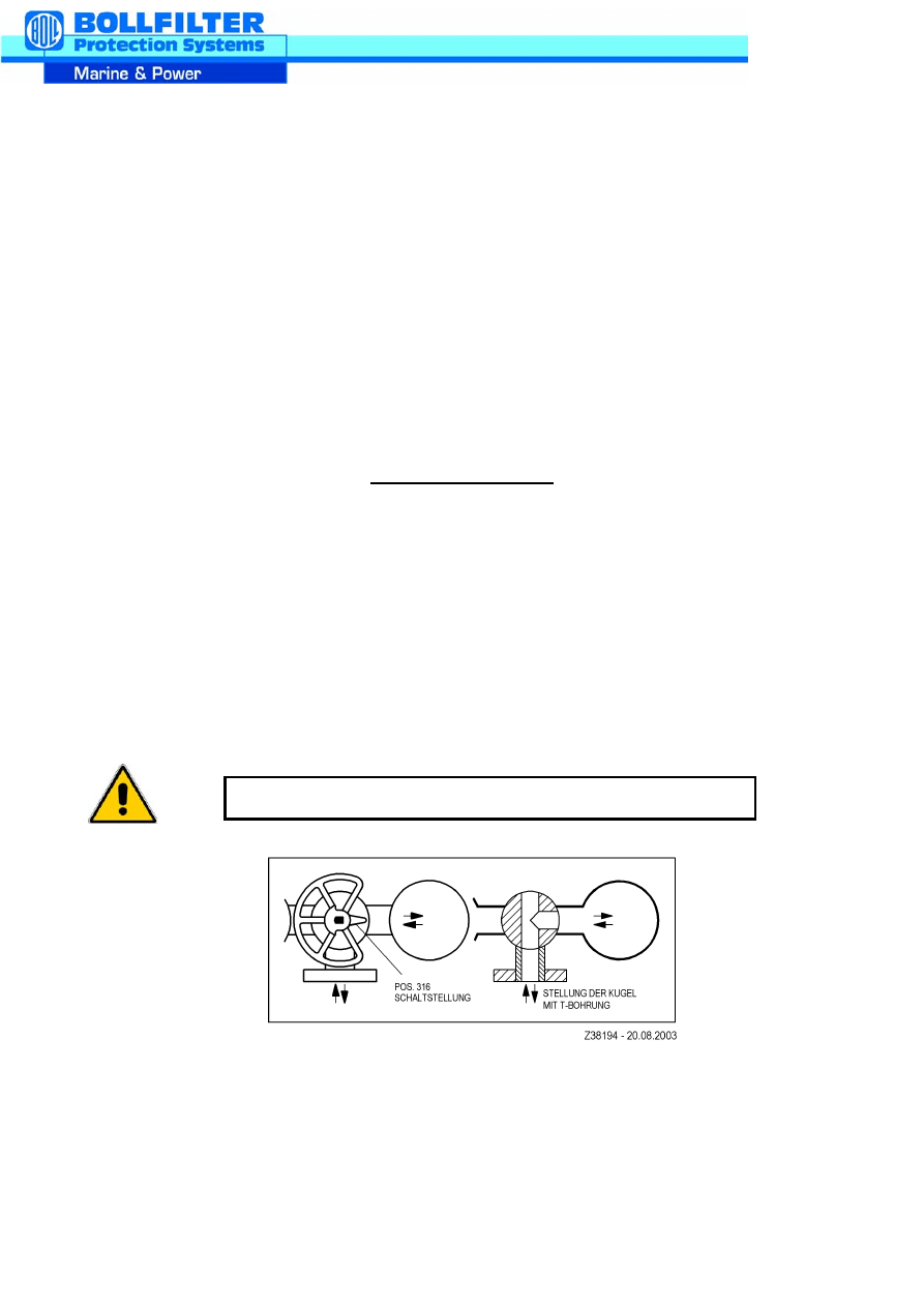
Item 16
Change-over position
Position of the ball
with T-bore
It is imperative to mark the ball position on the housing.
3.
Cleaning
3.1
Remove O-ring (13).
3.2
Remove both supporting rings (6) with the ball packing ring (7) and the cup springs
(15).
If difficult to move, press ball (12) and supporting ring (6) out of the housing with the
handle of a hammer.
3.3
Loosen and unscrew nut (8) with safety plate (17) on the spindle (11).
3.4
Check position of ball (12) as shown in drawing Z 37628.
3.5
Press ball (12) sideways out of the housing (1).
3.6
Press spindle (11) into the housing and remove.
3.7
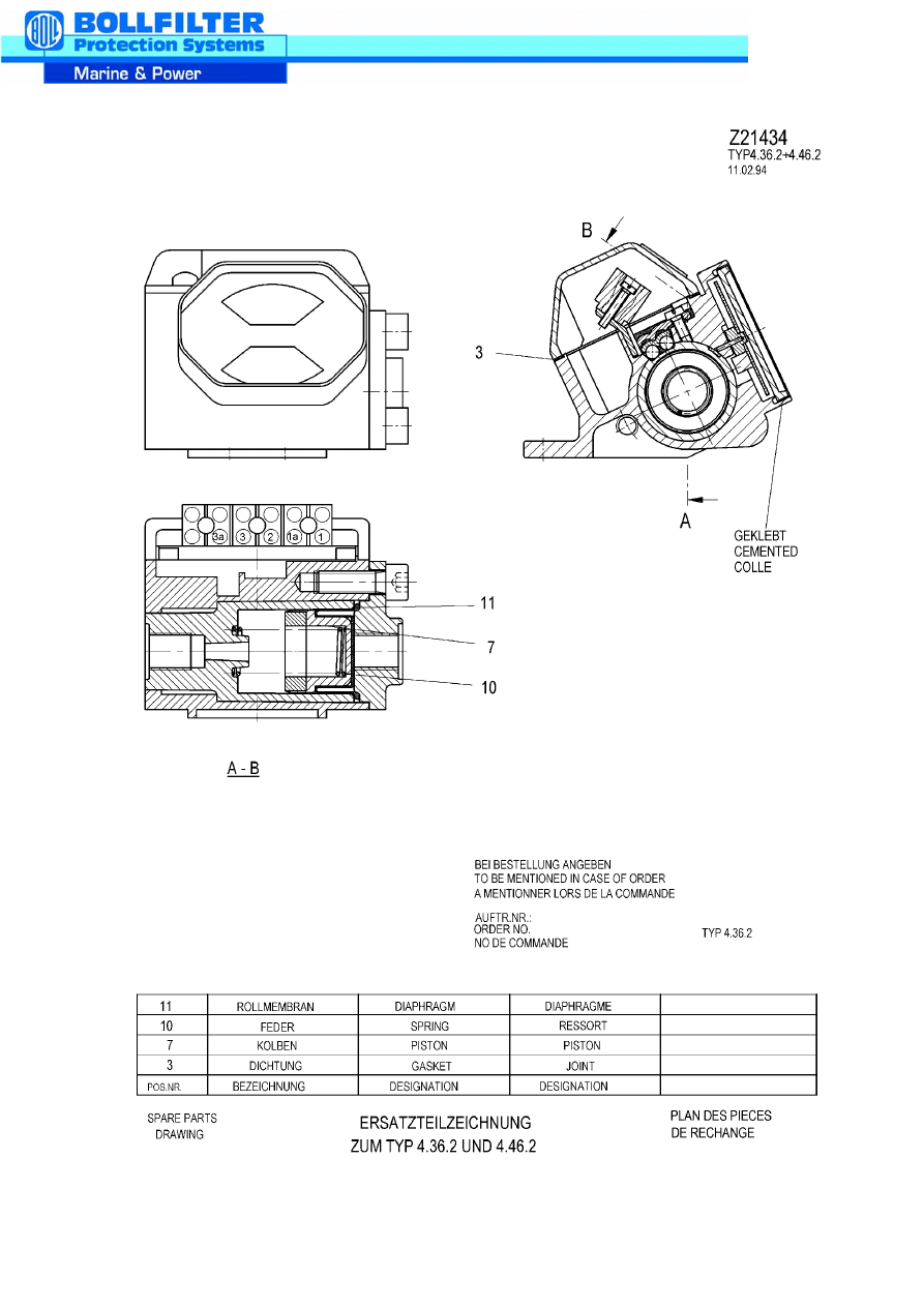
Dismantle thrust ring (8a) with packing ring (10 and 10a).
3.8
Pull O-ring (9) off spindle (11).
3.9
3.10 Clean housing (1), ball (12) and spindle (11), remove any sedimentation.
4.
Assembly of the ball valve
Before assembly of the ball valves, all parts must be cleaned, checked for
damage, if necessary replaced, and all packing rings must be renewed.
The O-rings must be assembled in accordance with the relevant regulations
and with the appropriate tools.
4.1
Grease spindle (11), mount sealing washer (10a) and O-rings (9).
4.2
Introduce spindle (11) through the side opening from inside into the shaft bore.
4.3
Press spindle (11) into the bearing assembly.
4.4
Install packing ring (10) with thrust ring (8a).
4.5
Screw on nut (8) with safety plate (17) and tighten.
4.6
Position spindle (11) with the flattened shaft ends at right angles to the bolted flange
port (in position illustrated).
4.7
Insert ball (12) through the side opening in the housing (1) into the flattened shaft
end of the spindle (11). Incorrect installation is not possible owing to the gearing.
4.8
Press ball (12) right through and position it centrally in the housing (1).
Only dismantle ball packing ring (7) in supporting rings (6) if
damaged. Caution! Packing rings are made of PTFE, do not
damage running surface!
Always renew the O-ring (9) and the sealing washer (10a).
Ensure ease of movement and secure nut (8) with safety plate
(17) by bending it over.
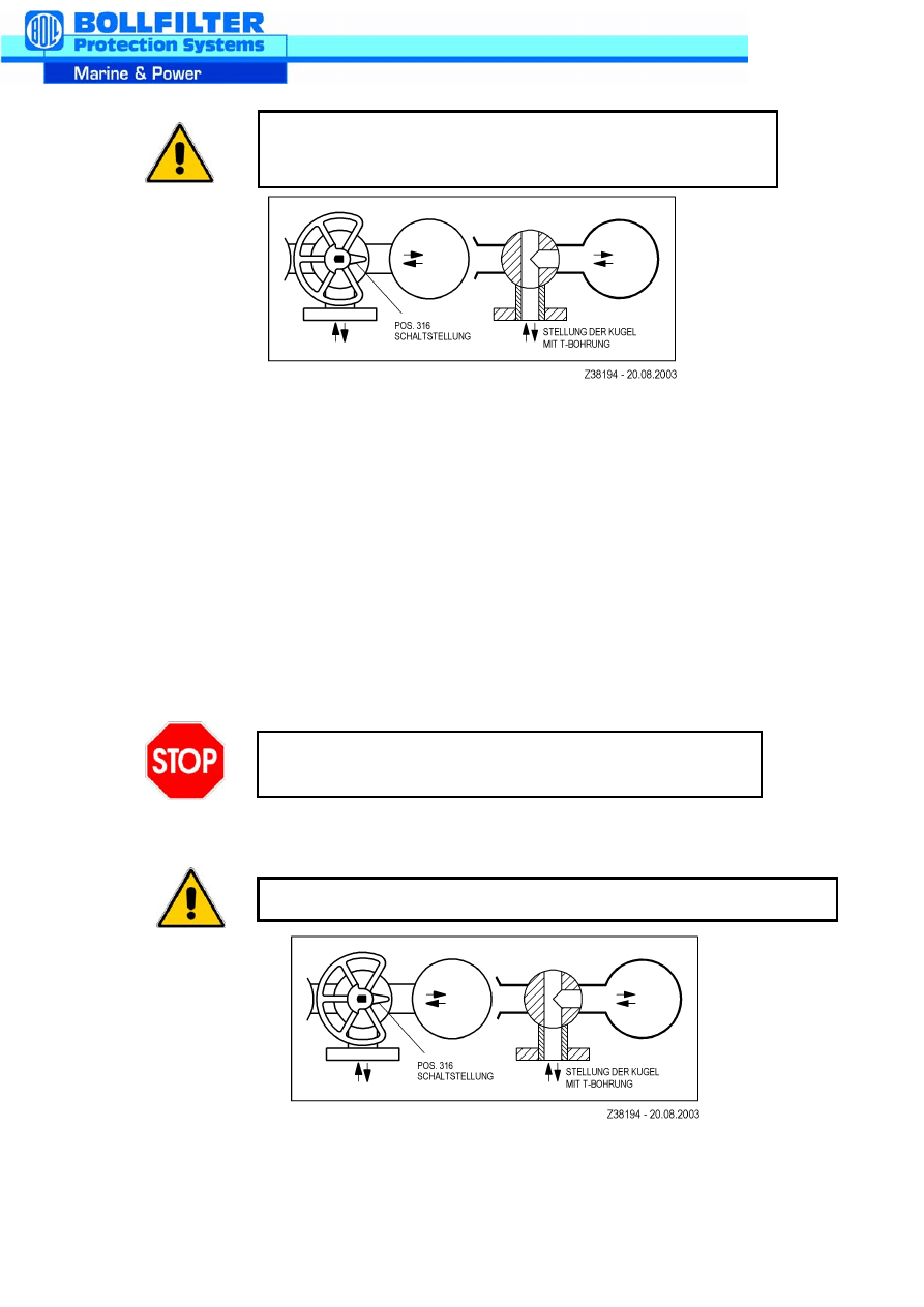
Item 16
Position of the
Change-over position ball with T-bore
4.9
Insert ball packing ring (7) and O-ring (14) into the supporting ring (6).
4.10 Introduce supporting rings (6) uniformly on both sides into the housing (1).
4.11 Insert cup spring (15) and O-rings (13) with grease or Vaseline into the supporting
ring (6).
4.12 Remove the star wheel (16) before installing the upper ball valve.
4.13 Introduce ball valve from above into the duplex filter and bolt loosely to the
connection flanges.
5.
Dismantling and assembly of the lower ball valve
5.1
Undo the bolts from the lower flange and pipe connections.
5.2
The upper ball valve remains on the duplex filter.
5.3
Item 16 Position of the
Change-over position
ball with T-bore
Move ball (12) into the marked position (see 2.7).
The ball (12) and spindle (11) are geared so that the correct
flow is guaranteed!
RISK OF INJURY:
The ball valve falls downwards when the bolts are removed.
It is imperative to mark the ball position on the housing (1) (see 2.7).
6.
Cleaning and assembly of the ball valve, as described in sections 3 + 4
7.
Commissioning
7.1
Introduce ball valve from below into the duplex filter.
The star wheel (16) must move freely on both shaft ends of the upper and lower
spindles (11). The star wheel (16) is geared in such a way that it cannot be mixed
up with the two shaft ends of the spindle (11). The position indicator (16) and the
ball bore are facing in the same direction, see Z38194.
7.2
Join the dismantled filter bowl again to the ball valve. Tighten the anchor bolts of the
filter bowl again.
7.3
Tighten the flange connections.
7.4
Renew flat packing ring on the pipe connection.
7.5
Mount pressure equalising cock.
7.6
For commissioning the filter, refer to the operating instructions for the duplex filters
2.78.2 and 2.58.2
BOLL & KIRCH assumes no liability for any misuse of the product.
We reserve the right to change this description without any prior notice!
Check valve for ease of movement and flow.
Torque of the ball valve
DN 80
DN 100
DN 150
Size 08
Size 10
Size 15
32 NM
40 NM
60 NM
CLEANING THE MULTI-MANTLE FILTER ELEMENTS
1.
The multi-mantle filters consist of up to 6 nested filter elements.
Fields of application are filter meshes < 200 µm.
In order to prevent flow short-circuits, the joins of the individual components are sealed with O-rings.
2.
The admissible differential pressures depend on the multi-mantle filter diameter:
Filter Ø (mm)
∆p max. adm. (bar)
∆p max. oper. (bar)
86 - 230
8
1,2
290
5
0,8
356 - 434
3,5
0,8
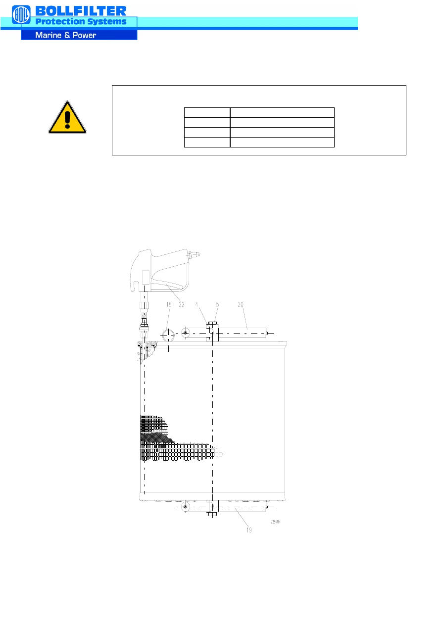
3.
Accessories of the filter element
The following items can be
supplied as accessories:
•
magnetic primary filter (19)
•
magnetic secondary filter (20)
4.
Maintenance
4.1
Clean and inspect multi-mantle filter elements at regular intervals. The length of these intervals
depends on the amount of dirt that has accumulated.
4.2
Carry out the first cleaning operation immediately after the installation has been flushed. A rising
pressure loss is a sign of increasing dirt accumulation.
The differential pressure is not to exceed 0.8 or 1.2 bar (suitable monitoring appliances are available
from BOLL & KIRCH).
5.
Cleaning
5.1
Shut off single filter or change over duplex filter. Release pressure from the filter housing by undoing
the venting screw and remove the housing cover. Open the drain screw in the filter base and drain
contents completely. Slacken the self-locking nut (4) on the central tie rod (5) and lift out the inner
filter with the lifting eye (18). Lift the remaining filter elements out individually by gripping the inside of
the filter ring.
5.2
Place the individual filter elements into containers with cleaning agent and brush off with not too hard
a brush (e.g. nylon brush).
5.3
Now blow compressed air at about 4 bar through the filter element cleaned in the above manner
from the clean side. To this end insert the cleaning gun type 5.02 (22) into the openings located in
the upper filter ring and blow through the filter surface from the inside with up and down motions.
5.4
In the case of persistent dirt or paint encrustation, place the filter into a with cleaning agent (to sheet
KV 349) and allow to soak for up to 4 hours. Make sure that the filter is not completely immersed but
that the upper ring remains free. This prevents dirt from reaching the clean side.
5.5
Remove filter and continue to treat as described under points 5.2 and 5.3.
5.6
If necessary, repeat points 5.4 and 5.5.
5.7
For final cleaning, rinse the filter in clean cleaning fluid (e.g. petroleum ether, paraffin, hot water or
similar) and blow through again. Then check fabric for cleanness and damage. Assess cleaning
effect by holding the filter element against the light. Use a torch for finer fabrics. If the light
penetrates evenly, the fabric has been cleaned well.
5.8
Check all seals including cover seals. Seals which have become hard and deformed must be
renewed without fail.
Before you open the filter chambers, observe the operating instructions for
single and duplex filters.
5.9
Insert the individual elements in the filter housing. Place the self-locking hexagonal nut, item 4, on
the central anchor and tighten using the tightening torque depending on the thread size.
6.
Cleaning appliances
6.1
2 cleaning containers.
6.2
Cleaning gun, type 5.02.
6.3
10 mm spanner.
6.4
Compressed air connection, max. 6 bar.
For particularly convenient and thorough filter cleaning we recommend our cleaning trolley type 5.04
with cartridge filter, pump and cleaning gun.
BOLL & KIRCH assumes no liability for any mistakes by any misuse of the product.
We reserve the right to change this description without any prior notice!
Self-locking nut tightening torque, item 4, or magnet star.
for anchor
Tightening torque Nm
M12
15 Nm
M16
30 Nm
M24
120 Nm
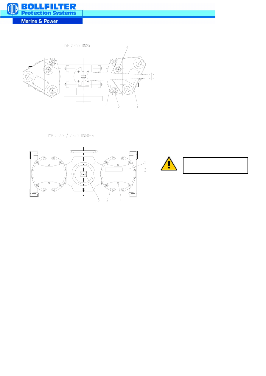
COVER SECURING DEVICE FOR DOUBLE FILTERS
The function of the cover securing
device is to prevent the uncontrolled
excape of lubricantes and fuels in the
case of operating errors. The cover
plate (2) covers a minimum number of
cover screws (3), so that the cover (1)
cannot be removed with out actuating
the venting facility (4).
The filter chamber is relieved through
the venting screw (4). With the correct
switching position, the service pressure
of the filter chamber falls immediately
and hardly any fuel excapes. Otherwise,
the venting screw is immediately closed
and the fuel discharge is limited.
BOLL & KIRCH assumes no liability for any mistakes due to misuse of the product.
We reserve the right to change this description without prior notice!
Operation:
1.
Establish on the circuit diagram (5)
with chamber is switched off.
2.
Unscrew the venting screw of this
chamber (4) to the point where the
cover plate (2) can swivel over the
cover screws (3)
3.
Loosen cover screws (3) and remove
cover (1).
4.
Assemble in reverse order
5.
For sieve cleaning and
commissioning, see Sieve
Cleaning Operating Instructions
and Double Filter Operating
Instructions.
Check seals items 6 and 7
for damage.

Europa / Europe
BOLL & KIRCH Filterbau GmbH
Cyprus
Postfach 1420, 50143 Kerpen
M.I.E. Services Ltd.
Siemensstr. 10-14, D-50170 Kerpen
The Hawk Building
Tel.: +49/2273/562-0
CY-3032 Limassol
Fax.: +49/2273/562-223
Tel.: +357/25889999
E-Mail: info@bollfilter.de
Fax.: +357/25345639
E-mail: info@mieserv.cy.net
BOLL & KIRCH Filterbau GmbH
Geschäftsstelle Nord
Denmark/Sweden/Iceland/Norway
An der Strusbek 34
BOLL & KIRCH FILTER Skandinavien ApS
22926 D-Ahrensburg
Skovlytoften 26
Tel.: +49/4102/4740-0
DK - 2840 Holte
Fax.: +49/4102/4740-22
Tel.: +45/ 45/ 42 12 00
E-Mail: ursula.klein@bollfilter.de
Fax.: +45/ 45/ 42 12 99
E-mail: skandinavien@bollfilter.dk
IVG Pumpen- und Filtrationstechnik Gera
Prehlis 13 A
Finland
D-07552 Gera
OY Insalko AB
Tel.: +49/365/42 00 07 4
P.O. Box 156
Fax.: +49/365/42 00 07 5
FIN - 00181 Helsinki
E-Mail: ivg-neubert@t-online.de
Tel.: +358/9-68 53 86 0
Fax.: +358/9-68 53 87 0
BOLL & KIRCH Filterbau GmbH
E-Mail: insalko@insalko.fi
Geschäftsstelle Süd
Rangaustraße 7 a
Greece / Bulgaria
D-91639 Wolframs-Eschenbach
FILTERKON
Tel.: +49/9875/884 (Herr Henkelmann)
8, Mitsaion Str.
Tel.: +49/9875/971865( Herr Pirkl)
GR - 117 42 Athen
Fax.: +49/9875/885
Tel.: +30/210/9217671
E-Mail: norbert.henkelmann@bollfilter.de
Fax.: +30/210/9242242
E-Mail: filterko@otenet.gr
Italy
Schmachtl KG
DeCoSta S.R.L.
Pummererstraße 36
Via Bicetti de Buttinoni, 12
A - 4021 Linz
I-20156 Milano
Tel.: +43/732/76 46 0
Tel.: +39-02-38 00 52 83
Fax.: +43/732/78 50 36
Fax.: +39-02-38 00 36 31
E-Mail: office.linz@schmachtl.at
E-Mail: sales@decosta.it
Belgium/Luxembourg
Netherlands
AUXIMECA S.A.
Lubrafil B.V.
Glasstraat 19
Aalborg 2
B - 2170 Merksem
NL - 2993 LP Barendrecht
Tel.: +32/3/64 66 180
Tel.: +31/180/556255
Fax.: +32/3/64 69 398
Fax.: +31/180/556265
E-mail: info@auximeca.be
E-mail: lubrafil@lubrafil.nl
Croatia
Marine Trade d.o.o.
Russia / Ukraine / Belorussia
Vladimira Nazora 6
Dr. Alexej Simakov
HR-47000 Karlovac, Kroatien
P.O. Box 133
Tel.: +385-47-61 13 65
RUS - 198262 St. Petersburg
Fax.: +385-47-61 42 81
Tel. + Fax.: +7/812/376-6240
E-Mail: marine-trade@ka.hinet.hr
E-Mail: simakov@rol.ru
Verkaufsbüro
Agency
Bei Service- und Ersatzteilbedarf wenden Sie sich bitte an das Stammhaus oder an unsere Niederlassungen, Vertretungen oder Service-Stellen.
If you need service or spares for our products please contact our head office or our branch-offices, agencies or service-stations.
Lager
Stockist
Austria/Czech.Rep./Rep. Of
Slovakia/Slovenia
Deutschland/Germany
Zentrale / Headquarters
Service
Service

Asien / Asia
Spain/Portugal
Hongkong/P.R. of China/Macao
Bollfilter España S.L.
BVI Marine Systems Ltd.
Zona Cami Ral
HK - Hong Kong SAR
Paseo del Ferrocarril, 339 3-2
Tel.: +852-3181 7830
E - 08860 Castelldefels
Fax.: +852-2541 2171
Tel.: +34- 93-634 26 80
Fax.: +34-93-665 22 79
E-mail: carlos.martinez@bollfilter.es
India
A.K. Dutta
Switzerland/Liechtenstein/Poland
IND - Navi Mumbay 400614
Equipement Industriel Genève S.A.
Tel.: +91/22/75 60 147
120 Route de Frontenex
Fax.: +91/22/75 60 146
CH - 1208 Genève
E-mail: akdutta123@vsnl.net
Tel.: +41/22/73 59 50 0
Fax.: +41/22/78 66 17 1
Japan/Taiwan
E-Mail: info@eig-sa.ch
Blohm & Voss Japan Ltd.
Japan / Kobe, 651-0085
Turkey
Tel.: +81/78/242 8550
Ares Ltd.
Fax.: +81/78/242 85115
DES Sanayi Sitesi
117.Sokak C24 Blok
81260 Y.Dudullu / Istanbul
Singapore / Malaysia / Indonesia
Tel: + 90 (0) 216 4996252 Pbx
MNM Corporation Pte. Ltd.
Fax: + 90 (0) 216 4996276
SGP - Singapore 629021
E-Mail: sami.uygurer@aresmakina.com
Tel.: +65/6/86 14 22 2
E-Mail: burak.pabuccoglu@aresmakina.com
Fax.: +65/6/86 24 22 2
E-Mail: mnmcorp@mbox4.singnet.com.sg
U.K. and Ireland
BOLLFILTER UK LTD
South Korea
Commerce Park, Whitehall Road
Blohm & Voss (Korea) Ltd.
GB - Colchester, Essex C02 8HX
ROK - Pusan / Korea
Tel.: +44-120679 22 34
Tel.: +82/51/74 05 70 1
Fax.: +44-1206-79 30 04
Fax.: +82/51/74 05 70 4
E-Mail: john@bollfilteruk.co.uk
E-Mail: bvkorea@kornet.net
Amerika / America
Australien / Australia
BOLL FILTER CORPORATION
Peacock & Smith Pty Ltd.
USA - Plymouth, MI 48170
AUS - Kensington Vic. 3031
Tel.: +1 -734-451-4680
Tel.: +61/39/37 64 49 9
Fax.: +1 -734-451-4681
Fax.: +61/39/37 62 16 5
E-Mail: latorre@bollfilterusa.com
E-Mail: filters@peacocks-aus.com
Motor-Services Hugo Stamp, Inc.
Afrika / Africa
USA - Ft. Lauderdale, Florida 33315
South Africa
Tel.: +1 (954) 763-3660
Afrifil Industrial Filters (Pty) Ltd.
Fax.: +1 (954) 763-2872
ZA - Isando, 1600
Tel.: +27/11/452 5444
Brazil
Fax.: +27/11/609 9535
Petersen Matex Ltd.
E-Mail: sales@afrifil.co.za
BR - 20093-900-Rio de Janeiro
Tel.: +55/21/2211-5050
United Arabian Emirates
Fax.: +55/21/2518-2220
Middle East
E-Mail: Max.Herrmann@pml.com.br
M/S Safe Technical Supply Co. L.L.C.
P.O. Box 4832
Dubai
Tel.: +971-4-3243240
Fax.: +971-4-3243786
E-Mail: sales@emirates.net.ae
Document Outline
Wyszukiwarka
Podobne podstrony:
truck adblue emulator for man user manual
2 Good Practices for meat industry Manual
ME Duplex Filter
FilterBank3 manual
3751 truck adblue emulator for iveco user manual
truck adblue emulator for volvo user manual obdtoolshop
truck adblue emulator for daf user manual
Installer For WindowsVista Operation Manual
AVC IntraEncoder for Compressor install manual English 2
Statistical Signatures for Fast Filtering of Instruction substituting Metamorphic Malware
Statistical Signatures for Fast Filtering of Instruction substituting Metamorphic Malware
Forex Online Manual For Successful Trading
Efficient VLSI architectures for the biorthogonal wavelet transform by filter bank and lifting sc
Applications of polyphase filters for bandpass sigma delta analog to digital conversion
Kyocera Duplexer DU 30 Parts Manual
Kyocera Duplexer DU 25 Parts Manual
Manual therapy for trigger points
PostHaste for GibbsCAM Format Reference Manual 50408g
więcej podobnych podstron