
PostHASTE Post-Processor Formatting Reference Manual © 1989-2002 Paul Andrews & Ground Support
i
50408g
Post
HASTE
Postprocessor
Formatting Reference Manual
Have you seen Appendix E? IF NOT, YOU SHOULD! Please see page 119 now.
What is this manual and who is it for?
This is the second of two manuals written for PostHASTE – it contains detailed information regarding the
PostHASTE formatting templates.
This manual was written for people who are already familiar with the basic concepts covered in the manual
entitled Getting Started with PostHASTE. If you haven't already, please read (or review) that manual.
What is PostHASTE?
PostHASTE (sometimes referred to as “the post” for short) is a software system that translates your CAM
system's tool motion output (CL files) into 'NC program' text (or 'ASCII') files to drive NC or CNC
machines. PostHaste can create programs in any of these formats:
• EIA (sometimes referred to as 'ISO') standard:
EIA programs are the most common type of machine control files; they typically use G, X, Y, Z, T
and/or M codes (among others) for various machine movements and functions.
• 'Conversational':
Conversational programs are usually somewhat similar to EIA programs, but typically have words
or phrases (such as 'LINE' or 'ARC') in place of some or all of the standard letter codes.
• Tab-sequential (or “columnar”):
These types of programs are not very common anymore, but are sometimes needed for older (e.g.
'Bandit less expensive (such as Emco-Maier) machines. These programs have the various
numerical values arranged in columns (instead of using a letter); the location (or spacing) of the
numbers within each line determines the significance of the value. For example the first column
may be an X position, the second column the Y position, and so on.
Limitations of PostHASTE
Some machines do not use the above conventions and therefore PostHaste may not be suitable for use in generating
NC programs for them; among them are some Brother and older Mazak ('Mazatrol' language) machines and several
others. If you have any doubt as to whether or not PostHaste is suitable for your machine, then call us; we will be
able to help you determine its suitability. If it is not, then you may either purchase a postprocessor that has been
customized to the specific machine, or get as close to it as possible by configuring PostHaste, then editing the NC
code (using a text editor) to suit your machine exactly.

ii
PostHASTE Postprocessor Formatting Reference Manual © 1989-2002 Ground Support Numerical Control Systems
Table Of Contents
What is this manual and who is it for? ........................................................................................... i
What is PostHASTE? ...................................................................................................................... i
Limitations of PostHASTE.............................................................................................................. i
1.
POSTHASTE BASICS...................................................................................................... 1
1.1
How PostHaste works...................................................................................................................1
1.2
Template file extension naming conventions..............................................................................1
2.
FORMAT TEMPLATES - THE BASICS ........................................................................... 2
2.1
Overall structure of the template file..........................................................................................2
First - the NAME line.....................................................................................................................2
The address (letter) formats............................................................................................................2
Commands and 'Switches' ..............................................................................................................3
Basic rules regarding commands.......................................................................................................... 3
The “Sequences”.............................................................................................................................3
2.1.1
Comments in the format...........................................................................................................4
3.
THE LETTER FORMATS ................................................................................................. 5
C__ (the COLUMN number - used only for columnar programs - see examples later) ..................... 6
S_ (the “Spaces” number - used only for columnar programs - see examples later) ........................... 6
+ (the plus sign).................................................................................................................................... 6
- (the minus sign).................................................................................................................................. 6
> (the “up to...” sign)............................................................................................................................ 6
A numeral (in the above example the number: 3) ................................................................................ 6
. (a decimal point)................................................................................................................................. 7
> (the “up to...” sign [again]) ............................................................................................................... 7
A number (in the above example the number: 4) ................................................................................. 7
x - the OUTPUT character. .................................................................................................................. 7
The OUTPUT character for COLUMNAR style programs: ................................................................ 7
3.1
Advanced letter formatting..........................................................................................................8
3.1.1
Suppression of a letter (“numbers only” output) .....................................................................8
3.1.2
Letter format modifiers ............................................................................................................8
Add __ .................................................................................................................................................. 8
DivBy _ and DivInto _ ................................................................................................................... 9
Force..................................................................................................................................................... 9

Inc 10
IncFrom _ ........................................................................................................................................... 10
Limit __ __ ......................................................................................................................................... 10
Clamp __ __ ....................................................................................................................................... 10
Mod __ ............................................................................................................................................... 11
Modal ................................................................................................................................................. 11
Mult __ ............................................................................................................................................... 11
No-Opt................................................................................................................................................ 12
Sub __................................................................................................................................................. 12
3.1.3
How Letter Format Modifiers are used together ...................................................................12
Hierarchy of Modifiers:................................................................................................................13
Notes re “LIMIT checking”: ........................................................................................................14
Regarding IncFrom: .....................................................................................................................14
4.
COMMANDS AND 'SWITCHES'.....................................................................................15
What's a Switch?...........................................................................................................................15
4.1
List of Commands and Switches (the ones that are not used inside sequences) .................15
Note: See section 5.3 for commands that are used only inside of sequences...............................15
We have listed all of the commands and switches in this section in alphabetical order, except for...15
4.1.1 Ask .........................................................................................................................................16
How to make the Ask repeat ............................................................................................................... 17
4.1.2 AskPeckClear?.......................................................................................................................17
4.1.3 ByDiameter?
(lathe
only) ......................................................................................................17
4.1.4 Comment................................................................................................................................18
4.1.5 Convert ..................................................................................................................................18
4.1.6 Coolant...................................................................................................................................19
Examples: .....................................................................................................................................19
4.1.6.1
Using [Cool] in an IF statement.................................................................................19
4.1.7 DComp...................................................................................................................................19
4.1.8 Drive ......................................................................................................................................20
4.1.9 Each .......................................................................................................................................20
4.1.10
EOB ('End Of Block' characters) .......................................................................................20
4.1.11
EOF ('End Of File' characters) ...........................................................................................21
4.1.12
Feed and Rapid...................................................................................................................21
4.1.13 FeedType ............................................................................................................................21
4.1.14 First#?.................................................................................................................................21
4.1.15
HCode, VCode, DCode and FeedCode ..............................................................................21

iv
PostHASTE Postprocessor Formatting Reference Manual © 1989-2002 Ground Support Numerical Control Systems
4.1.16
HCode2, VCode2, and DCode2 .........................................................................................22
4.1.17 Inc/Abs................................................................................................................................22
4.1.18 Inch/MM.............................................................................................................................22
4.1.19 Incremental? .......................................................................................................................22
4.1.20 Ignore..................................................................................................................................23
4.1.21 Leading0s?..........................................................................................................................23
4.1.22 LocalOutput? ......................................................................................................................23
Important! Make sure your [Work] numbers match! ...................................................................24
4.1.23 ModalGs .............................................................................................................................24
4.1.24 ModalLetters.......................................................................................................................24
4.1.25
Notes: / EndOfNotes (or EndNotes)...................................................................................25
4.1.26 Rename ...............................................................................................................................26
4.1.27
ReturnPlane or RetPlane.....................................................................................................26
4.1.28 RevSigns.............................................................................................................................27
4.1.29 RoundToQuad?...................................................................................................................27
Automatic 'round center to startpoint' feature .................................................................................... 27
4.1.30 RevTurret2? ........................................................................................................................28
4.1.31 Sequence#s .........................................................................................................................28
4.1.32 Spaces? ...............................................................................................................................29
4.1.33
SpeedType (lathe only).......................................................................................................29
4.1.34 Spindle ................................................................................................................................29
4.1.35 SpliceSubs?.........................................................................................................................29
4.1.36 Thread.................................................................................................................................29
4.1.37 TLAxisEnabled?.................................................................................................................30
4.1.38 Tolerance ............................................................................................................................30
4.1.39 Tools ...................................................................................................................................30
4.1.40 UpperCaseComments? .......................................................................................................31
4.1.41 Verbose? .............................................................................................................................31
4.1.42 Work ...................................................................................................................................31
4.1.43 WorkDefault .......................................................................................................................32
4.1.44 ZRestart?.............................................................................................................................32
4.2
Arc processing commands and switches...................................................................................33
4.2.1 ArcPlane.................................................................................................................................33
Using the [ArcPlane] variable in an ArcCode sequence .................................................................... 34
4.2.2
Cw and Ccw...........................................................................................................................35
4.2.3 CtrCode ..................................................................................................................................35

4.2.4
CtrCode>180 and CtrCode360 ..............................................................................................35
4.2.5 CtrIncremental? .....................................................................................................................36
4.2.6 ByQuadrants? ........................................................................................................................36
4.2.7 Helical? ..................................................................................................................................36
4.2.7.1
Helical arcs - Handling special cases.........................................................................36
So, what value is output with the K? .................................................................................................. 37
What if you want some other K value? .............................................................................................. 37
4.2.8 MaxRad..................................................................................................................................38
4.2.9 MinRad ..................................................................................................................................38
4.2.10 MinArc ...............................................................................................................................38
4.3
Special commands for Columnar style formats.......................................................................39
4.3.1 Spaces ....................................................................................................................................39
4.3.2 Dummy ..................................................................................................................................39
5.
THE “SEQUENCES” ......................................................................................................40
5.1
Using Variables: .........................................................................................................................40
For a complete list of variable names and descriptions, see Appendix A....................................41
5.2
The Sequence Descriptions ........................................................................................................42
5.2.1
The standard sequences .........................................................................................................42
5.2.1.1 StartCode ...................................................................................................................42
5.2.1.2 1stToolChange ...........................................................................................................43
5.2.1.3 ToolChange................................................................................................................44
5.2.1.4 Infeed .........................................................................................................................44
5.2.1.5 OutFeed......................................................................................................................44
5.2.1.6 EndCode ....................................................................................................................45
5.2.2 Canned
Cycles .......................................................................................................................46
5.2.2.1
Two ways to output canned cycles: 'canned' and 'longhand' .....................................46
You may “mix and match” your drilling cycle methods... ................................................................. 46
5.2.2.2 Cancel ........................................................................................................................47
“End cancel” vs. “End” ...................................................................................................................... 47
The 'Cancel' sequence......................................................................................................................... 47
5.2.2.3
Peck drilling (The Peck and ChipBreak cycles). .......................................................47
…but what if my machine does not have a Peck or ChipBreak cycle? .............................................. 48
5.2.2.4
Advanced canned cycle control. ................................................................................48
5.2.3
Controlling 'modality' - the “Force?” option .........................................................................49
5.2.4
Additional sequences for special purposes ............................................................................50

vi
PostHASTE Postprocessor Formatting Reference Manual © 1989-2002 Ground Support Numerical Control Systems
5.2.4.1
Sequences for custom and multi-line movements LineCode, RapidCode and ArcCode
(CwCode, CCWCode) .....................................................................................................................50
Important notes regarding ArcCode (and CwCode and CcwCode): .................................................. 51
LineCode and RapidCode sequences ................................................................................................. 51
5.2.4.2
AutoThread (used for lathe only)...............................................................................51
[TParams] variable .......................................................................................................................52
"Individual" thread parameter variables available ............................................................................. 52
5.2.4.3
Index (used for machines with rotary axes)...............................................................53
... for machines with ONE rotary axis ..........................................................................................53
Which letter should I use on my INDEX line? / Do I need the minus sign?.................................. 53
INDEX definition when rotary axis on CAD model does not match machine orientation ................ 54
... for machines with TWO (or more) rotary axes ........................................................................54
5.2.4.4 Stop ............................................................................................................................54
Handling ‘Optional Stop’ (OPSTOP) CL records.............................................................................. 55
5.2.4.5
Upon, UponRec & Cycle sequences..........................................................................55
Upon .............................................................................................................................................55
The Every, PreScan and Unique modifiers ........................................................................................ 56
The Relate option for 'Upon ... Unique' sequences: ........................................................................... 57
UponRec and Cycle ......................................................................................................................58
Using variables with UponRec or Cycle to handle the incoming values......................................60
Cycle (using variables) .................................................................................................................60
More UponRec and Cycle examples.............................................................................................61
5.2.5
CallMe and Call (User-defined sequences and 'reusing' sequences)....................................61
5.3
Commands that can be used inside of sequences.....................................................................62
5.3.1 Call.........................................................................................................................................62
5.3.2 Comments ..............................................................................................................................63
5.3.3
If, Else and EndIf ...................................................................................................................63
5.3.4 File .........................................................................................................................................64
What the File commands can do for you ........................................................................................... 64
How to use the File commands .......................................................................................................... 64
* Important notes re the Alias and Empty commands... ..................................................................... 66
5.3.4.1
'File' usage example: Creating a 'tool list' at the top of the program. ........................66
5.3.5
NoEol and EOL......................................................................................................................67
5.3.5.1 EOL............................................................................................................................68
5.3.6 Set ..........................................................................................................................................69
5.3.6.1
Limitations of SET commands ..................................................................................70

6.
WORK FIXTURE OFFSETS (G54, ETC.): HOW THEY [WORK] ..................................71
The 3 issues (in the format template) that control Work offsets ..................................................71
Work offsets "in a nutshell" .........................................................................................................71
But, what if you DON'T want work offsets in your NC programs?.............................................72
Handling 'non-standard' work offsets (G54.1 P_ , G15 H_ ... etc.)..............................................72
Details, details, details..................................................................................................................72
The Work line ..................................................................................................................................... 73
The WorkDefault line ......................................................................................................................... 73
The [Work] variable (used in the sequences) ..................................................................................... 73
Changing [Work] offsets between drilling cycles. ............................................................................. 74
Getting rid of redundant G54 (et al) codes ......................................................................................... 75
7.
SPECIAL FEATURES.....................................................................................................76
7.1
Using Equations (mathematical operations)............................................................................77
7.1.1
Mathematical symbols and functions ....................................................................................77
Hierarchy of operations & use of parentheses..............................................................................78
7.2
Suppressing line numbers and outputting blank lines............................................................78
Suppressing line numbers.............................................................................................................78
Outputting blank lines ..................................................................................................................79
7.3
'Text output' and text {variables} .............................................................................................79
7.3.1
Direct ('hard-coded') text output ............................................................................................79
7.3.2
Regarding use of 'quotes' (and outputting quotes in your code)............................................80
7.3.3 Using
{text
variables} ...........................................................................................................80
7.3.4
Important information regarding text and text variables: ......................................................81
7.4
“Search and Replace” ................................................................................................................81
Avoid 'double-replacements'! .......................................................................................................82
The NoComment option................................................................................................................82
The ALL option.............................................................................................................................83
7.5
If / Else Logic ..............................................................................................................................84
Logical operators ('Equals', 'Greater than', etc.) ...........................................................................85
Testing 2 conditions: Using AND and OR with IF.......................................................................85
7.6
Outputting subs (subprograms), and the automatic 'multiple part' program feature ........85
7.6.1
Basic Fanuc setup example....................................................................................................86
7.6.2
Automatic multiple part programs.........................................................................................86
7.6.2.1 Sub
numbering...........................................................................................................87

viii
PostHASTE Postprocessor Formatting Reference Manual © 1989-2002 Ground Support Numerical Control Systems
7.6.3
Sequences, variables and switches used for subs...................................................................88
7.6.3.1 SubCall sequence .......................................................................................................88
7.6.3.2
SubStart, SubEnd, and Between sequences ...............................................................88
7.6.3.3
[Sub], [SubLine] and [Times] (sub variables) ...........................................................89
7.6.3.4
Switches used to control subs ....................................................................................89
SpliceSubs? switch ............................................................................................................................. 89
7.7
The PostHaste.log file (for “debugging”)..................................................................................90
Inhibiting the log file for faster processing. .................................................................................91
8.
“SPECIAL CASE” TACTICS & NOTES......................................................................... 93
8.1
Concerning incremental / absolute output and the [IncMode] variable ...............................93
8.2
How to format “P1=” type codes...............................................................................................94
8.3
'Block deletes' on multi-part sub calls ......................................................................................95
9.
APPENDIX A - LIST OF VARIABLES.......................................................................... 96
Categories of variables .................................................................................................................96
The variables.................................................................................................................................97
9.1.1.1
Variables that apply to movements in general...........................................................98
9.1.1.2
Variables that can be used to format arc movements ..............................................101
9.1.1.3
Variables related to “point-to-point” Drilling cycles...............................................102
9.1.1.4
Variables set from the Tool or Tool Change information........................................104
9.1.1.5
Variables used for subroutines or subprograms.......................................................107
9.1.1.6 Text
Variables..........................................................................................................107
9.1.1.7 Prompted
Variables..................................................................................................108
9.1.1.8
Variables used for Wire EDM posts. .......................................................................109
9.1.1.9
General Purpose (Misc.) variables...........................................................................110
10. APPENDIX B - LIST OF “RETIRED” FUNCTIONS. .................................................. 112
11. APPENDIX C - APT-CL RECORDS RECOGNIZED ................................................... 113
CL records IGNORED by PostHaste: ........................................................................................113
CL records recognized by PostHaste:.........................................................................................114
12. APPENDIX D - HANDLING ROTARY AXES ............................................................ 116
Definitions:....................................................................................................................................... 116
12.1
[RotAngle] vs. [AAxis], [BAxis] and [CAxis]...................................................................116

12.2
Where do the actual rotary angle values come from?....................................................116
12.2.1 MULTAX
data .................................................................................................................116
12.2.2
Coordinate system (CS or CSYS) data.............................................................................117
12.2.3
TLAXIS record data.........................................................................................................117
TLAxisEnabled? switch .................................................................................................................... 118
12.2.4
ROTATE, ROTHED or ROTABL records ......................................................................118
The VertCSame? switch .............................................................................................................118
13. APPENDIX E - WHAT'S NEW WITH POSTHASTE AND THIS MANUAL? .............119


PostHASTE Post-Processor Formatting Reference Manual © 1989-2002 Paul Andrews & Ground Support
1
1. PostHASTE Basics
PostHASTE is basically a translator that reads CL (“Cutter Location”) tool path data and outputs it
according to a formatting template that you can easily modify.
PostHASTE operates quite simply - it usually only prompts you for two things...
- the CL file to open and
- (optionally) which machine format file you want to use.
...PostHASTE will then generate the NC program and save it according to the information you enter in
response to the prompts.
This manual discusses how to modify the format templates to suit your needs.
1.1 How PostHaste works
PostHaste gets all of the configuration information for each machine from a format template file. (In the
context of this manual, we will refer to it as either simply the format or the template.)
All you have to do to change a machine program format is to modify the contents of the corresponding
template file. This can be done easily with any word processor or text editor.
The primary purpose of this manual is to explain how to modify the template(s) to achieve the desired
output for 3 and 4 axis milling and 2 axis lathes. (Other instruction manuals are available for Mill-Turn
machines [that is, lathes with live tooling] and 5 axis milling machines.)
1.2 Template file extension naming conventions
We recommend using the file name extensions (the three characters that typically follow the period in a file
name) in the chart below to differentiate between format files for various types of machines.
The numbers in the extensions indicates the number of supported axes.
Extension(s) Machine
type(s)
.pM2 to .pM5
Milling (2 axis to 5 axis machines)
.pT2 to .pT4
Turning (Lathes) - 2 to 4 axis
.pU2 to .pU5
mUltifunction (Mill-Turn) machines - 2 to 5 axis.
.pL2 to .pL5
Laser...
.pF2...
Flame or plasma
.pP2...
Punch presses
.pE2 wire
EDM
.pW2...
Water jet

2
PostHASTE Post-Processor Reference Manual
© 1989-2002 Paul Andrews & Ground Support
2. Format templates - the basics
This section will familiarize you with the overall structure of the format file.
We highly recommend that while reading the following information, that you also load a format template
file into the editor of your choice so you can follow along on your screen.
2.1 Overall structure of the template file
Now, all of the formatting information that PostHASTE requires is placed in the format template file in
these 4 basic areas:
1. The
NAME
line
2. The address (letter) formats
3. Commands
and
switches
4. The
“Sequences”
The following four sections briefly describe what these do Please take a look at a template file (on your
screen) while you read the following; doing this will greatly help you get a good idea of how the template
file works.
First - the NAME line
When you edit a template file, you will notice that the word NAME is the first thing in the format. The
NAME line starts the description of each machine format. Without a NAME line, you don't have a
format. Sorry - that's just the way it is.
After the required NAME line, the remainder of the template can be broken into 3 sections (as described in
brief below). These 3 sections look basically the same from one machine format to the next, so the easiest
way to create a new NC code format is to copy an existing machine format template, then alter it to fit your
needs.
The address (letter) formats
This lists the letters that can be used in your format - in the order that they will appear in the lines of
machine program code - and the exact formatting of the numerical values that accompany each letter.
Here's an excerpt from the letter format section of a Fanuc template:
O >4
O can be up to 4 digits, no decimal.
N >4
G >2
G can be up to 2 digits, no decimal.
X ->3.>4
X can have minus sign, up to 3 before, up to 4 after decimal.
Y ->3.>4
When you're ready to learn all about letter formatting, see section 3.

PostHASTE Post-Processor Formatting Reference Manual © 1989-2002 Paul Andrews & Ground Support
3
Commands and 'Switches'
After the letter formats, there is typically a page or two full of commands such as...
ModalGs 0 1 2 3 73 74 76 80 81 82 83 84 85
Sequence#s N 0 1 1 Char, Freq, Increment, Start
HCode X
VCode Y
FeedCode F
Spaces? Y Spaces between words?
...Commands like the above tell the post basic information that is used commonly in many areas of the final
machine program. (You may see section 4.1 to learn more about all of the available commands and
switches.)
Basic rules regarding commands
PostHaste expects to find the commands and switches written in a particular way; therefore any
modifications that you make to the file must be done in STRICT ADHERENCE to the rules outlined here.
As you have already seen (on the NAME line); this is the kind of structure that PostHASTE expects to find
in the format:
- a command word (such as “name”), then
- a SINGLE SPACE (to separate the word from the following instructions), then
- the parameters (letters, numbers or other specific words) pertaining to that particular command. If
there is more than one parameter, then the parameters are always separated by a single space.
Note: As you will see below, you must always be careful to not use more than one space between
parameters. If you do, then you will turn the remainder of the line into a 'comment' that PostHaste will
ignore.
The “Sequences”
The sequences describe where all of the words (letters and numbers) appear in the final program. They look
similar to an NC program, as these sequences show:
StartCode
O[Program#]
G90
End
1stToolChange
N[Block] T[Tool] M6
G0 G40 G80 G[Work] X[H] Y[V]
G43 Z[D] H[Lcomp] M[Direct] S[Speed]
M[Cool]
End
Drill
G81 X[H] Y[V] Z[D] R[RLevel] F[FRate] F. in, R. out.
end cancel
Cancel

4
PostHASTE Post-Processor Reference Manual
© 1989-2002 Paul Andrews & Ground Support
G80
end
...
EndCode
G28 G49 Z0 S100
G28 G91 X0 Y0 T[Tool1] M6
G90 M30
End
There are sequences to describe every portion of a finished machine program. You can get more
information on sequences in section 5.
Please note that again, all of the words in the sequences must be separated by a single space.
2.1.1 Comments in the format
NOTE: PostHaste will IGNORE ANYTHING ON THE LINE THAT HAS 2 OR MORE
ADJACENT SPACES BEFORE IT - this allows you to put comments in the file in either of these
2 easy ways:
1. Simply move the cursor a few spaces past the end of a command line, then type your
comment.
2. Type any comment on its own line - just make sure that the line has some leading spaces.
We HIGHLY recommend that you make liberal use of comments! They take only a few
seconds to write, but could save you many minutes (or hours!) of frustration later when you need
to make changes to your format!
CAUTION: BE CAREFUL NOT TO ACCIDENTALLY “COMMENT OUT” part of the actual
formatting information by mistakenly entering 2 spaces in place of 1!
PostHASTE Post-Processor Formatting Reference Manual © 1989-2002 Paul Andrews & Ground Support
5
3. The Letter Formats
This is a series of lines that each start with a specific character (usually a letter) followed by some numbers
and signs. This is a list of all of the characters that your NC machine needs (and in the order that they will
appear on any line of NC code). Add, change and/or delete letters and/or instructions so that they are
arranged in the order that they appear in a line of NC code and are formatted according to the following
information (if you look at the templates you will see something like these).
Helpful hint: When reading the letter formats, the arrow (>) means “up to”.
/ 00
% 00
“00” (“No digits before the decimal, no decimal, then no digits after”) is the format for any character that you wish to
appear by itself (that is, with no numbers) - which makes it perfect for describing the percent sign (%) or “block delete” (/)
characters, as it does in these examples.
N >4
N address: (NO - sign allowed,) up to 4 characters (no decimal).
X ->3.>4
X address: - sign allowed, up to 3 places before the decimal, a decimal, then up to 4 digits after.
F >32
F address: (NO - sign allowed,) up to 3 places before the decimal, (NO decimal,) then 2 digits after. The post will add
trailing zeros; thus a F value of -2.0 will be output as F200
G 2
G address: always 2 digits; a G value of 0 will be output as G00
R +->24
R address: + sign is mandatory (unless the value is negative, in which case the '-' will appear), up to 2 places before the
(invisible) decimal, then 4 after (adds trailing 0s such that an R value of 1.5 becomes R+15000).
You can see that the formatting options above gives you a lot of flexibility and are relatively self-
explanatory.
(Note: The examples above do not show any of the “advanced character formatting” that can be done - as
detailed in section 3.1.)
NOTE: You can also format lower case letters. PostHaste will accept characters with ASCII values
between 33 (!) and 122 (z). (The exclamation point [!] is a special case - read about it below in the
section entitled “Suppressing line numbers and outputting blank lines” - section 7.1.)

6
PostHASTE Post-Processor Reference Manual
© 1989-2002 Paul Andrews & Ground Support
The “maximum” possible letter format is something like this:
? C__ S_ +->_.>_ x
...where the “?” is the character (usually a letter) to be formatted, the “blanks" (_) can be any numeral, and
the “x” is an optional character (or a set of empty quotes, like “”. Empty quotes here suppresses the output
of the letter altogether. See section 3.1 [Advanced letter formatting] for more on this.)
Here's what each of the characters in the formatting lines do:
C__ (the COLUMN number - used only for columnar programs -
see examples later)
The number following the C notes the Column number at which this word starts. Note that there is a space
after the number to separate this information from the next part of the line. (Note: There are special
commands [Spaces and Dummy] that are needed for columnar style programs - read about them in section
4.3: Commands and Switches.)
S_ (the “Spaces” number - used only for columnar programs - see examples later)
The numeral after the S determines how many spaces this word will take in the NC block. (Note: There are
special commands [Spaces and Dummy] that are needed for columnar style programs - read about them in
section 4.3: Commands and Switches.)
+ (the plus sign)
This causes PostHaste to output a + sign on the number if it is not negative. It must be the first formatting
character in this line of your file if used at all.
- (the minus sign)
As would be expected, this causes PostHaste to output a - (“minus”) sign on the number if it IS negative. It
must be the next formatting character if a - sign is ever to be used for this character address.
> (the “up to...” sign)
This (actually the “greater than” sign) is supposed to be an arrow that means that the number of digits
before the decimal point can be “up to N places” (where the N is the next number on the format line
[explained below]) and causes NO LEADING ZEROS TO BE OUTPUT in this address. IF THIS ARROW
IS LEFT OUT, THEN THE POST WILL ADD LEADING 0s so that the number of digits before the
decimal will always be the following number...
A numeral (in the above example the number: 3)
If the above “up to” arrow is used then this is the MAXIMUM number of digits that may appear before the
decimal point.
If the above “up to” arrow is NOT used then this is the number of digits that will ALWAYS appear before
the decimal point.

PostHASTE Post-Processor Formatting Reference Manual © 1989-2002 Paul Andrews & Ground Support
7
. (a decimal point)
The presence of the decimal point in the line here will indicate that this address requires a decimal point.
Conversely; if this character is absent, then it will not be output in the NC code. You can also use
COMMAS (,) instead of decimal points - this is common for use with European machine tools.
> (the “up to...” sign [again])
Just like above; this arrow means that the number of digits AFTER the decimal point can be “up to N
places” (where the N is the next number on the format line [explained below]) and causes NO TRAILING
ZEROS TO BE OUTPUT in this address. IF THIS ARROW IS LEFT OUT, THEN THE POST WILL
ADD TRAILING 0s so that the number of digits after the decimal will always be the following number...
A number (in the above example the number: 4)
This is always a single digit that indicates the number of digits available AFTER the decimal point:
If the above “up to” arrow is used then this is the MAXIMUM number of digits that may appear after the
decimal point.
If the above “up to” arrow is NOT used then this is the number of digits that will ALWAYS appear after
the decimal point.
x - the OUTPUT character.
If for any reason you wish to have a letter placed in the NC program INSTEAD of the one that is actually
described by the formats, you may place this letter here. This comes in handy when for instance, the same
letter must be formatted differently when it is used in different places. Case in point is the Bridgeport
milling control: any negative Z value with a minus (like “Z-1.5”) is usually BELOW the Z0 point, but in
the case of drilling cycles, no minus sign is required for the Z! Here are the lines that you can put in your
format to accommodate this condition:
Put these 2 lines in the “letter formats” section:
Z ->3.>4
A >3.>4 Z
A canned cycle description should look like this:
G81 X[H] Y[V] A[D] F[FRate]
|
In this case a normally unused letter (A) is called in the drilling cycles, but the format line of the letter A
ends with “ Z” so that a Z will actually come out in the NC code. It will also appear WITHOUT a minus
sign (because of the absence of the “-“ in the “A” format line).
In other words, the post formats for A, but outputs a Z. This is only one example of how this can be
used; the possibilities are endless!
The OUTPUT character for COLUMNAR style programs:
This output character designation works slightly differently when you are formatting a COLUMNAR style
program (remember as mentioned above; the SPACES line designates a format as columnar); IF NO
OUTPUT CHARACTER IS SPECIFIED, THEN A SPACE WILL BE OUTPUT IN PLACE OF THE
LETTER INSTEAD OF THE LETTER ISTELF. (That's why in the examples above the T is repeated at the
end of the T format line, and also why the note for the K address says that no letter will appear in the NC
program; because there is no K repeated at the end of the format line.)

8
PostHASTE Post-Processor Reference Manual
© 1989-2002 Paul Andrews & Ground Support
Note: There are special commands [Spaces and Dummy] that are needed for columnar style programs -
read about them in section 4.3: Commands and Switches.
3.1 Advanced letter formatting
In addition to the “basic” formatting options described above, there are some other things you can add to
the end of a letter format line to achieve many other operations. Here is a list of them:
3.1.1 Suppression of a letter (“numbers only” output)
You can suppress the output of a letter by putting a set of empty quotes after the letter format (where you
would usually place the “output character”). For example, this line could be used to put “Line numbers” in
the program without the “N” preceding them:
N >4 ''
This would cause the resulting program to look like this:
instead of this:
1 O12
N1 O12
2 G0 G28 X0 Y0 Z0
N2 G0 G28 X0 Y0 Z0
3 T1 M6
N3 T1 M6
3.1.2 Letter format modifiers
Letter formats can also have specific modifiers assigned to them for the purpose of Limit checking,
conversion factors (MODulo, SUBtraction, MULTiplication and/or ADDition by any value[s]), Modal
and Force attributes (read below) and 2 different types of “Incremental” designation: INC and IncFrom.
These modifiers can simply be appended to the end of any “Letter format” line (as shown in the various
examples in the discussion below).
Note: - You can ADD or MULT by a LETTER, not just a number. We had originally planned to let you
ADD or MULT a variable, but this way is much better because the letter you add or mult can be assigned to
different variables at different times (and in turn, even IT can be made incremental, and have any other
letter added, multed... etc), so it is infinitely more flexible.
This is a quick list of how they work (the “_” in the headings below represents a number or letter that the
modifier requires):
Add __
Follow ADD with any number or variable that you want to add to the initial word value. The example
below adds .1 to all Z values:
Z ->3.>4 Add .1
As you might suspect, negative numbers can be used to effectively “subtract” a number from a particular
word - in this case we're now subtracting .1 from the Z values:
Z ->3.>4 Add -.1
You can use the Add option to add variables as well as numbers to your program values. This is handy for
using on some milling machines that require that the RLevel value be added to the Z value for drilling. Just
assign a substitute letter to be used to output the drilling Z and add the RLevel variable like this:
C >3.>4 Z Add [RLevel]

PostHASTE Post-Processor Formatting Reference Manual © 1989-2002 Paul Andrews & Ground Support
9
Although you can easily add variables to your values, you can't subtract them in this way because the post
won't recognize “-[RLevel]”. To handle this problem, we've given you the Sub modifier below...
DivBy _ and DivInto _
These are modifiers that allow you to use division in 2 different ways:
- DivBy _
...divides the letter's value by some other number or variable before outputting.
If you want to divide the letter's value BY some number or variable, then use DivBy.
The following example will divide all X values by 2:
X ->3.>4 DivBy 2
...Resulting in the code "X12." being output as "X6.0"
- DivInto _
...divides the number or variable following DivInto into the letter's value before outputting it.
As an example, to output the pitch on a tapping cycle you would format the letter to return the
RECIPROCAL of the [Step] value by dividing the value INTO 1 (e.g. "1/pitch") like this...
Q ->3.>4 DivInto 1
...then simply use Q[Step] in the TAP sequence. This would result in "Q20." being output for a 1/4-20 tap,
for instance.
___
Like all letter math modifiers, DivInto and DivBy...
- can be followed by numerical constants, other variables or other letters.
- should NOT be used on N (line) numbers. (You can get around this to SOME extent by adding the line
"each N[Block]" to your format...)
If the use of either of these modifiers results in an attempted "division by zero", then...
- the user will be warned
- the letter value will be left 'unmodified' (the division will not take place), and
- the post will continue.
Force
Always forces the appearance of the word (or just the letter if used in conjunction with MODAL.)
Example: This is used commonly in Heidenhain conversational formats, where a particular letter (such as
'R') must appear (by itself) on every line, but a number only appears when the value has changed.
R ->3.>4 Modal Force

10
PostHASTE Post-Processor Reference Manual
© 1989-2002 Paul Andrews & Ground Support
Inc
The value of this word will be output as an increment from its last absolute value. (Last abs. value is
subtracted.) Example:
X ->3.>4 Inc
IncFrom _
Specifies another letter: The LAST absolute value of THAT letter will be subtracted from the value of this
word.
Example: Some controls require that the Z value for drilling be measured incrementally from the R value.
In those cases, use this format:
z ->3.>4 Z IncFrom R
(NOTE: In this case, make sure that the R is processed BEFORE the z, otherwise the Z output will be
incremental from the LAST value of R instead of the current value.)
Limit __ __
Follow this with 2 numbers: the minimum and maximum limits. A warning message will appear if the tool
motion file causes the letter to be outside the specified range. When the warning message appears, the user
will have the option to continue or abort. (If the user chooses to continue, the 'bad' number WILL appear in
the output.)
Note: A single letter may not be formatted using Limit and Clamp. You may only use one of these on each
letter format.
Clamp __ __
Similar to Limit above, follow this with 2 numbers to indicate the minimum and maximum allowable
values of the letter being formatted. Unlike the Limit action, the post will not output a warning, but it will
'clamp' the output value so that numbers larger than the 'upper clamp' value will be output AS the 'upper
clamp' value. Likewise; values smaller than the lower clamp value will be output AS the lower value.
Examples:
The number would
normally be output
this way,
but the letter is formatted
like this,
...so it actually appears
in the code like this:
Why?
F9523.4
F >4.>3 Clamp 1 8000 F8000.0
Because it is over the
upper limit (8000), it
is output as F8000.
S22
S >4 Clamp 50 9000
S50
It is below the lower
limit (50) so it is
output as S50.
This is especially helpful when formatting the feed rate letter (especially if used for 'inverse time feed rate',
where very short movements can produce very large F values).
Note: A single letter may not be formatted using Limit and Clamp. You may only use one of these on each
letter.

PostHASTE Post-Processor Formatting Reference Manual © 1989-2002 Paul Andrews & Ground Support
11
Mod __
This is the mathematical modulo function which returns the 'remainder' of a division operation. This is used
commonly for machines that have a rotary axis with a 'numerical limit' of 360, but can be used for other
things as well.
Here are simple examples that show how the Mod function affects the output of various values:
0 mod 360 = 0
1 mod 360 = 1
320 mod 360 = 320
360 mod 360 = 0
361 mod 360 = 1
410.03 mod 360 = 50.03
720 mod 360 = 0
725 mod 360 = 5
-45 mod 360 = -45
-360 mod 360 = 0
-363.41 mod 360 = -3.41
...etc.
(Please note that the Mod function also works the same regardless of whether the incoming value is a
positive and negative numbers.)
Here is an example of how to use the Mod modifier in your template:
To format the letter A properly for a 4 axis mill to get this output (when the rotary table keeps turning the
same direction as it approaches, then continues past the '360 degree' boundary)...
...
X.1 A-356.0
X.2 A-358.0
X.3 A0.0
X.4 A-2.0
X.5 A-4.0
...
... use the 'modulo' function on the letter A like this:
A ->3.>3 Mod 360
Modal
Causes a word to be suppressed (not output at all) unless its value has actually changed since the last time
the letter was output.
(Note: This has exactly the same effect as listing the letter in the ModalLetters command line.
See section 4.1.24 for information on the ModalLetters command.)
Mult __
Just like the Add modifier, follow MULT with any number or variable that you would like to multiply by
the initial word value. This example “doubles” the X value by multiplying by 2:
X ->3.>4 Mult 2
For example, the sign of a number can be reversed by multiplying it by -1 like the letter X shown here:
X ->3.>4 Mult -1

12
PostHASTE Post-Processor Reference Manual
© 1989-2002 Paul Andrews & Ground Support
Also, the mult modifier can be used to “divide” a number by using the reciprocal of that number. For
instance, a number can be “divided by 2” by simply “multiplying by 1/2” like this:
X ->3.>4 Mult .5
No-Opt
Code "zero optimization" can be overridden with the No-Opt modifier.
By default, when the post outputs a "0" value along with "floating point" words (such as "X ->3.>4"), it
suppresses the decimal point so that the output appears as "X0" instead of "X0." . This can save a
significant amount of code in a long program. If, however, you want to prevent this optimization from
taking place, you can add the "No-Opt" modifier onto any letter in the letter format section like this:
X ->3.>4 No-Opt
This will cause a zero value to be output as "X0.".
(Remember, upper or lower case doesn't matter on the modifiers.)
Sub __
As you would expect, follow Sub with any number or variable that you want to SUBTRACT from the
initial word value. The example below subtracts 1.5 from all X values:
X ->3.>4 Sub 1.5
Even though you could do the same thing by Adding “-1.5”, you can't use the Add to subtract variables -
that's why we've given you the Sub option. Here's how we could subtract the RLevel variable from the Z
value (if we wanted to):
Z ->3.>4 Sub [RLevel]
(Remember to use [brackets] when specifying variables.)
One of the nicest by-products of this modifier is the ability to make any letter's value "incremental" from
any other variable. For example, if we wanted the letter W to be output incremental from the current X
(horizontal position) value, we could format it in this way :
W ->3.>4 Sub [H]
3.1.3 How Letter Format Modifiers are used together
Sometimes, you must use more than one modifier to get the results you want.
As an example...
Giving the MODAL modifier will prevent PostHaste from repeating the same values on later lines if the
value of that letter has not changed. Some conversational machines require the letter to be output by itself
(without the numerical value) if the value has not changed, such as the “R F M” required on all moves by
the Heidenhain conversational format. In these cases, add the FORCE parameter AND the MODAL
parameter (the order does not matter) like this:
X >3,>4
R >2 Modal Force
F >31 Modal Force
M >2 Modal Force

PostHASTE Post-Processor Formatting Reference Manual © 1989-2002 Paul Andrews & Ground Support
13
Notice that no “Modal” modifier need be given to X. This is because the post assumes that certain codes
(including the HCode, VCode, DCode, and FeedCode - usually X, Y, Z, and F) are modal. If you want any
of them NOT to be modal, then add a “ModalLetters” line (somewhere after the letter formats) to change
the default “modality” of these (and any other) letters. Read more about the ModalLetters command below.
Any letter(s) can be designated as incremental simply by using the INC modifier. For example, the
following letter formats tell the post to output only the Z axis movements as incremental, while outputting
absolute X and Y values:
N >4
G >2
X ->3.>4
Y ->3.>4
Z ->3.>4 Inc
I ->3.>4
...
The sample formatting lines below could be used for a Bridgeport milling post set up to output in Metric
mode from American (SAE) dimensioned geometry. For metric, we simply multiply the X,Y, and Z values
by 25.4 (the “inch-to-metric” conversion factor).
Furthermore, the 2 lines below allow 2 different “Z” formats: one that allows negative numbers (for
contour milling), and another used for drilling. Z values used in drilling (“canned”) cycles on a Bridgeport
machine can have no minus sign, and are measured incrementally down from the RLevel point. So, we
have a normal Z format line for contour milling, and we also format another letter (in this case “A”) to
output a non-signed incremental Z value with 2.54 mm ADDed to compensate for a .1” RLevel level. (If a
different vertical clearance value is used when designing the tool motion, then you must change this value
to match. For example, if you used .05” for the “rapid down” clearance, then use 1.27mm as the “additive”
in the post.)
The “Limit” values used in these examples are arbitrary - your machine may be quite different.
Z ->3.>4 Limit -150 125 Mult 25.4
A >3.>4 Z Limit 0 150 Mult 25.4 IncFrom Z
|
|
Notice: any “output letter” used
Use “IncFrom” to indicate
MUST follow the numeric formatting
letters measured incrementally
BEFORE Mult, Add, Limit and/or Inc.
from another letter.
After the “output letter”, the order of the rest of the modifiers (Mult, Add, Modal, Force, Limit, IncFrom
and Inc) makes no difference. For example, formatting the “secondary Z” using the line below would result
in exactly the same NC program, even though the modifiers are in a completely different order:
A >3.>4 Z IncFrom Z Mult 25.4 Limit 0 150
|
Notice: again, the “output letter” (Z) is BEFORE the modifiers.
Hierarchy of Modifiers:
There is a hierarchy to the order in which the numerical functions (Mult, DivBy, DivInto, Add, Sub,
Mod, Inc, IncFrom and IncSign) and Limit checks are performed (regardless of the order they are placed
in the format):
- First, the original value is multiplied by the multiplier,
- DivBy or DivInto are applied next,
- then addition and subtraction are performed,

14
PostHASTE Post-Processor Reference Manual
© 1989-2002 Paul Andrews & Ground Support
- modulo is then applied (to the total so far)
- the result is then checked against the limit values.*
- Next, the result is converted to incremental (if Inc or IncFrom is present)
- finally, the sign ( + or - ) of the resulting value is altered by IncSign.
* Note that the limit is checked before the value is made incremental. This has the effect of checking the
original “absolute” value (not the resulting incremental value) against the limits.
Notes re “LIMIT checking”:
• Limits are not checked on phrases that are the result of a “Replace” statement. In other words, if you
inadvertently replace a phrase with another that is beyond a limit, then no warning will appear.
• Limit values are Absolute! In other words, even if the letter is incremental, PostHaste will keep track of
the absolute value of the letter, and warn if the absolute position values indicated by the “Limit”
parameter have been exceeded.
Regarding IncFrom:
Always remember (as mentioned in the discussion above) that the value of any word modified by
INCFROM is affected by the CURRENT value of the “IncFrom” letter. This means that if a letter is
incremental from another letter on the same line of code, THE “INCFROM” LETTER (Z in the
examples here) SHOULD BE CALLED FIRST! This means that, of the 2 sample lines below, ONLY
THE SECOND WOULD PRODUCE THE PROPER RESULT. This is because PostHaste processes
the words in the order they appear * on the line. So in the first line below, it gets to the A value
BEFORE the Z has been set to the RLevel value, so in this case the A value would be output as
measured incrementally from whatever the Z value was BEFORE this line was processed.
Wrong: G81 X[H] Y[V] A[D] Z[RLevel] F[FRate]
Right: G81 X[H] Y[V] Z[RLevel] A[D] F[FRate]
* Remember that the order that the words appear in the sequences does NOT control the order that they
appear in the resulting code: that is determined by the order the letters are listed in the “letter format”
section of the Template.

PostHASTE Post-Processor Formatting Reference Manual © 1989-2002 Paul Andrews & Ground Support
15
4. Commands and 'Switches'
Commands and “switches” are used by PostHaste to describe certain aspects of the code for your machine.
These commands and switches are usually placed in the template after the letter format section and before
the sequences. These are all explained in detail in this section of the manual.
Note: There are also other commands that are used only inside of sequences; those are not discussed here –
see section 5.3 for those.
What's a Switch?
Any word that you see in the templates followed by a question mark (such as RevTurret2? or First#?) are
called “switches” because they refer to various code conditions that can be turned on or off with a “YES or
NO”. This is done simply by placing a Y or N after that switch. Watch for switches in the descriptions
below.
4.1 List of Commands and Switches
(the ones that are not used inside sequences)
Note: See section 5.3 for commands that are used only inside of sequences.
In the format template, any of the needed commands or switches should be listed AFTER the letter
formatting section, and BEFORE the first sequence. The order in which they are listed in your format is
usually not important. (Any exceptions to this will be noted in the corresponding sections below.)
We have listed all of the commands and switches in this section in alphabetical order, except for...
...commands and switches relating to the following topics, which are discussed in the sections noted here:
Topic:
Discussed in section:
Arcs 4.2
Columnar style formats
4.3
Subprograms (or Subroutines)
7.6
Commands that are used inside of sequences
5.3
16
PostHASTE Post-Processor Reference Manual
© 1989-2002 Paul Andrews & Ground Support
4.1.1 Ask
Use of this command allows you to have PostHaste ask you a question when it runs - the number you type
in response to the question then sets the value of any variable you choose. Any variable can be used, but
care must be taken to not overwrite a variable that has been set from the tool motion file (unless, of course,
that is what you really want to do).
Here's a simple example that changes the output at the end of your program from an M30 to an M99, based
on the value that the post asks you:
Ask [Val1] 'Enter 30 for a main program, 99 for a sub.' '30'
EndCode
M[Val1] (Outputs M30 for main program or M99 for a sub.)
End
The three parameters after the “Ask” are...
- The variable to set (Remember, there are 20 “unused” variables named Val1 to Val20 that you can use
that are not normally set from an incoming tool motion file).
- the first quoted phrase specifies the exact wording of the prompt.
- the second quoted phrase specifies the default answer.
The variable can then be used later in any sequence portion of the format to output a numerical value with
any letter.
Here are some examples of how you may use ASK in the template. First, you place any needed ASK
statement(s) in your template like this:
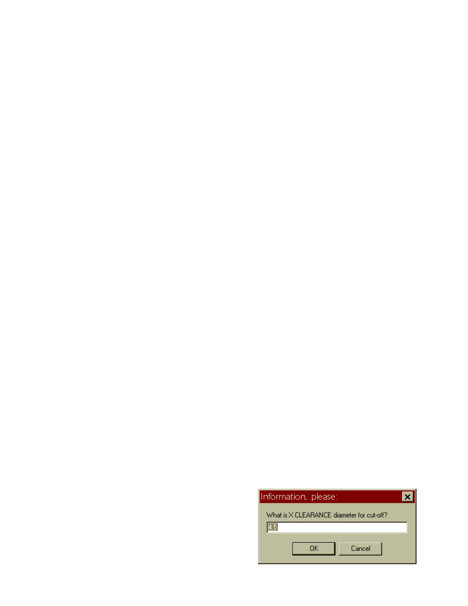
Ask [Val2] 'What is X CLEARANCE diameter for cut off?' '4.5'
Ask [Val3] 'Cut off Spindle Speed:' '200'
Ask [Val1] 'What is Z value for cut off?' '-3'
Then, you access the “asked” variable(s) in a Sequence, as in this example of an automated “cutoff” cycle
in the ENDCODE section of a lathe format:
EndCode
G0 Z.2 { Rapid to tool change position }
G28 U0 W0 M9 T[LastTool] { Cancel Offset for LAST tool. }
/0 M0
G50 X0 Z0
T1200 M[Cool]
G96 S[Val3] M[Direct] { Val3 is Cut off Spin. Speed
G0 Z[Val1] X[Val2] T1212 { Cut off Z,X: Val1,2
G1 X0 F.003
G0 X[Val2] { Clear to diam.
G28 U0 W0 T1200
/0 M99
M30
End
When PostHaste runs, a prompt dialog (like the one pictured
here) will appear for each “Ask” question. You can just
press ENTER to use the optional default value (in this case
4.5), or enter any other number you wish.

PostHASTE Post-Processor Formatting Reference Manual © 1989-2002 Paul Andrews & Ground Support
17
Warning:
Any time you add (what you think is) a 'new' variable to a post, make sure that that variable is NOT
being used for some other purpose in the post already! Before adding a new variable, ALWAYS do a
“Search” to make sure that you don't mistakenly re-use a variable that is being used for something else.
Making this mistake can result in VERY strange output - and a big mess to “debug”!
How to make the Ask repeat
You can have PostHaste ask any question just once per run, or make it ask the question(s) every time a
certain sequence is output. For instance, if you want a question to be asked every time a tool is changed
(for example), then simply place the Ask line(s) inside the ToolChange sequence. The same holds true
for any sequence. This comes in handy, for instance when formatting for a wire EDM to ask the user for
different “burn” settings every time an INFEED (Cuttercomp application) move is made.
If you would like a particular question asked only once per run, then simply place the ASK line
somewhere NOT within any sequence. (By the way, ASK lines are permissible within an IF structure.)
Whatever value the user enters in response to each question will become the value of the specified variable
until that variable is ASKed again, or until that variable is reset by something in the incoming tool motion
file. (Remember: if you use Val1 to Val20, then they normally won't be reset by incoming tool motion
[unless they are placed on a Cycle or UponRec definition line].)
4.1.2 AskPeckClear?
Setting this switch to Y tells PostHaste ask you for the peck clearance ([PeckClear] variable) value. If your
machine supports this parameter in its peck drilling cycle, then after each peck the tool will rapid down into
the hole to this distance from the current bottom before it starts feeding in on each subsequent peck. If you
set this switch to N, then PostHaste uses .050 as this value.
Note: if the Peck drilling sequence has “none” in it, the “longhand” peck drilling cycles will use this value
in the discrete movements that are generated.
Instead of having the post ask you for this value, you may 'hard-code' a particular value into your
tempate(s) by using a Set cd like this:
Set [PeckClear] to .03
4.1.3 ByDiameter?
(lathe only)
This is a “switch” that you may use for LATHE work to indicate how the vertical movements are
designated on your lathe. The X values on most lathes must be given as work DIAMETER, but some allow
you to use RADIUS values. If yours uses DIAMETRIC X values, the put a Y (for YES) after ByDiameter
like this:
ByDiameter? Y
If your lathe operates on RADIUS values for X then put N (for NO):
ByDiameter? N

18
PostHASTE Post-Processor Reference Manual
© 1989-2002 Paul Andrews & Ground Support
4.1.4 Comment
The Comment command indicates the character(s) that mark the beginning and end of 'comments' that the
machine will display on the screen, but otherwise ignore. On most modern controls, comments must be
enclosed in parentheses, so the Comment command will look like this:
Comment ( )
(Notice the spaces!) Some machines do NOT need a “end” comment character; in this case, just indicate
the comment START character:
Comment '
(Machines that use only a “comment start” character will ignore anything in the block that starts with the
comment character.)
Other machines may require more that a single character to start and end comments, like Heidenhain
controls, which we can also format by using this Comments command:
Comment (MSG, )
If your machine does not accept comments at all, then you need to disable the Comment command line
(by either completely deleting it, or placing a few leading spaces in front of the line so that PostHaste
ignores that line). Since the Comments command is what tells the post which characters to output before &
after any comments, the post logic is set up such that if there ARE no comment characters, then the post
will output no comments, so all comments (PPRINT records) found in the CL file will be ignored.
NOTE: Do NOT confuse the Comment command discussed above with the Comments command that is
used inside of sequences (to tell the post exactly where to put the comments in the code). See section 5.3.2
for information on the Comments command.
4.1.5 Convert
This works very much like the Replace command – except that it works on incoming CL records – that is,
before the CL data is processed by the post. There are many uses for this command – limited only by your
imagination. Here are a few ways that we've used it:
- Convert 'unrecognized' CL records into something that will be usable by the post. Example:
Convert 'PIERCE / OFF' to 'RAPID'
- Delete unneeded words or phrases in the incoming CL records. Example:
Convert 'TOOL NAME : ' to ''
- Use Convert in conjunction with an UponRec sequence to process incoming records in a 'non-standard'
way. Example:
Convert 'APPLY / LASER' to 'APPLY / 1' Set Val1 flag for laser, or.….
Convert 'APPLY / PUNCH' to 'APPLY / 0' Reset it to 0 for Punch mode.
Uponrec Apply [Val1] Val1 = laser flag.
if [Val1] = 1
G25 e5 Replace 'e05' with '(LASER OFFSET)'
!0 M44
!0 M45
endif
end
- 'Un-comment' an incoming comment in the CL file so that you can actually use data that was stored in
the CL file as a comment. Example:

PostHASTE Post-Processor Formatting Reference Manual © 1989-2002 Paul Andrews & Ground Support
19
Convert '$$-> CSYS' to 'CSYS'
You can use the Convert command multiple times.
NOTE: Like the Ignore command (below), Convert can be used either in the format template file, or in the
PostHASTE.CFG file. (Put Convert commands in your .CFG file for CL records that you want all of your
posts to use that same conversion, or put it in the template file[s] when you only want certain posts to
perform the conversion.)
Note: In templates that use Convert and Ignore commands, the Convert operation will be performed before
the Ignore command.
4.1.6 Coolant
Similarly to the Spindle command, the Coolant command is followed by the numerical values for the “M
codes” for the various available coolant modes.
Examples:
For APT-CL versions of PostHaste:
Coolant 8 9 7 50 M values: On, Off, Mist*, Hi pressure (Thru) On
* Note: If no “mist” coolant option is available on your machine, then put in the same M value that you are
using for flood [ON] coolant so that at least you will get coolant into the NC program if you mistakenly
choose MIST instead of FLOOD in your CAM system.
4.1.6.1 Using
[Cool]
in an IF statement
The [Cool] variable can be used in an IF statement, but you have to test its "Ordinal" value (0,1,2,3 etc.),
not the "M" value (8, 9, 7, 88 etc.), as you might think at first glance.
We did this so you can see if ANY coolant is 'on' by testing like this:
IF [Cool] > 0 ...
The value of the [Cool] variable - in the context of an IF statement – is shown below:
• Flood = 1 ( If [Cool] = 1 ... ) *
• Off = 0 ( If [Cool] = 0 ... etc. ) *
• Mist = 2
• THRU or HIGH = 3
4.1.7 DComp
The 3 values following the DCOMP command correspond to the machine's three diameter offset directions:
Left, Right, and Cancel, respectively.
DComp 41 42 40 Left, Right & Cancel G values
In a template that uses the above DComp line, the [Side] variable (usually used in an InFeed sequence like
this: G[Side]) will return a 41 when the CL file has a CUTCOM / LEFT record active, and 42 when a
CUTCOM / RIGHT record is active.

20
PostHASTE Post-Processor Reference Manual
© 1989-2002 Paul Andrews & Ground Support
4.1.8 Drive
The Drive command specifies the folder and, optionally, the extension of the final NC code file. This
allows you to route the NC code files for different machines into different directories with (optionally)
different extensions. (If DRIVE is not used, the NC code file will end up in same folder as the incoming CL
file, and it will have the default .NCC extension.)
If, for example, you would like to re-route the output into a different directory (in this case the C:\Acro-1
directory), then use the DRIVE line as follows:
Drive C:\Acro-1\ or Drive C:\ACRO-1\
NOTES:
- Make sure that you include the proper drive letter (in this case the "C:"). If you omit the drive letter,
the AutoOpen feature will not work correctly.
- You can use 'network' drives if you like. (example: “S:” )
- Note that if you are specifying only the folder (not the extension), then the last character MUST be
a backslash (\), because the post simply appends this parameter verbatim onto the front of the
finished NC code file name (since file names must be separated from the folder name by a
backslash).
You can also use the DRIVE parameter to specify a different file name extension, as in this example:
Drive
C:\Acro-1\*.ABC
This will cause the file to be output with the .ABC extension instead of the default .NCC.
Another possibility is to put the NC code files for all of your different machines into the same directory, but
use different file name extensions for each machine. You can do this by using the same path (folder) name
in the Drive commands for each machine format, but specifying a different extension for each.
4.1.9 Each
Use this command when you want a certain code to be output on each line of your NC program. It can be
followed by a letter or a variable as in these examples:
Each $0 or Each S[Speed]
4.1.10 EOB ('End Of Block' characters)
Use of the EOB (End of Block) command allows you to designate exactly what characters are output at the
end of each line (block) of your NC program in place of the standard "Carriage Return" (CR) and Line
Feed (LF) characters (ASCII values 13 and 10). This is done by listing the ASCII values of the desired
characters after "EOB" (separated by spaces, as usual).
For example, if you want a semicolon (;) instead of the LF, then your EOB command will look like this:
EOB 13 59
...because 13 is the ASCII value of the CR and 59 is the semicolon character.
You can have up to 20 numbers (ASCII characters) in your EOB "word".

PostHASTE Post-Processor Formatting Reference Manual © 1989-2002 Paul Andrews & Ground Support
21
4.1.11 EOF ('End Of File' characters)
Use this command in the same way as the EOB command above to designate any special "End of File"
characters you would like. This comes in handy if you need to output non-standard characters that can't be
easily formatted in the EndCode section.
Remember also that the last line of your program will include the standard CR,LF (unless you change it
with EOB as mentioned earlier), so the actual characters at the end of your file will be the 'EOB' PLUS the
EOF characters.
4.1.12 Feed and Rapid
The Feed and Rapid lines indicate the exact letter and numerical value that cause the machine to start
moving in 'feed' and 'rapid' modes, respectively. In the templates you will see a line that says:
Feed G1
That's because on the machines we use here a G1 indicates that a move at the specified feed rate is going to
be programmed in this block.
Likewise, the line...
Rapid G0
...describes the NC word that causes a rapid move to take place.
Some machines do use G1 for ALL linear moves (regardless of 'feed' or 'rapid' mode) and simply use a high
feed rate to move the machine in 'rapid' mode, so you could use something like this if you want:
Rapid G1 F1000
(Note: as of this writing, the Rapid line will accept two words [as shown immediately above], but the Feed
line accepts only one.)
4.1.13 FeedType
This line lists the letter and the possible values of the NC word that indicates the type of value that will
control the spindle speed: RPM and CSS (constant surface speed). The most common format for this is...
FeedType G 95 94 93 ( Val's for IPR, IPM, 'Inverse time' )
“Inverse time” is normally used only with 4-axis versions of the milling post-processor: it changes the feed
rate (usually F) code to output the reciprocal of the number of seconds required to complete the current
movement.
4.1.14 First#?
This switch indicates whether or no you want a Sequence (block) number on the 1
st
line of your program. If
you do, then follow FIRST#? with a Y (YES). If not, then use N (NO).
4.1.15 HCode, VCode, DCode and FeedCode
These commands are followed by the CHARACTER that corresponds to their function (the H, V, and D in
the 1
st
3 commands stand for Horizontal, Vertical, and Depth, respectively). For standard milling, these
characters are almost always X, Y, Z, and F. For standard turning work: HCode is Z, VCode is X, and the
FeedCode is usually F (DCode [depth] is not used for turning).

22
PostHASTE Post-Processor Reference Manual
© 1989-2002 Paul Andrews & Ground Support
4.1.16 HCode2, VCode2, and DCode2
Just like the HCode, VCode, and DCode designations, these allow you to designate the letters used (for 2-
turret lathes only) to indicate movements of the 2
nd
turret (in the case that they are different from the letters
used for the 1
st
turret). For instance, the Fanuc/Miyano lathe (with the drilling axis) uses a B for all
movements of the drilling axis, so we put the following line in our format template (and make sure in the
CAM system that all drilling is done on turret # 2):
HCode2 B
Then (when using turret number 2) PostHaste will automatically use output B instead of Z.
(Make sure you add the letter you use to the list of letter formats.)
NOTE: The RevTurret2? switch can be used to automatically reverse the sign of X axis value. Read about
it in section 4.1.30
4.1.17 Inc/Abs
This line indicates the letter and numerical values that set incremental or absolute programming mode on
this NC machine. You should include the following line in your template:
Inc/Abs G 91 90
... so the post will be able to detect that you have switched output modes.
This is an absolute necessity if you want to include any absolute code (G90) in an incremental (G91)
format program, and vice-versa.
Including a G91 or G90 word in any sequence (in formats using the “Inc/Abs G 91 90” line) will cause the
output of the HCode, VCode, DCode, and Rotary axis code (the one preceding any reference to
[RotAngle]) to be output in an incremental or absolute fashion, respectively. You can also use the
[IncMode] variable (read about this below) in place of the 90 or 91 to read and output the mode directly
from the tool motion file like this: G[IncMode] .
4.1.18 Inch/MM
The two numbers following this parameter indicate the value of the letter that switches the machine into
INCH and MM programming, respectively. These values will can be accessed in the sequences through use
of the [UnitMode] variable. The post automatically assigns 70 or 71 to [UnitMode] - so you only need to
use the "Inch/MM" line if you want different values. (Typically, a word like "G[Unitmode]" would be used
in the StartCode sequence to set the units of measurement for the entire program.)
Inch/MM 70 71
4.1.19 Incremental?
Setting this switch to "Y" tells the post that when the post starts outputting the code, that you want it to be
in incremental mode. The default mode of the post is "N". Be aware, however, that if you have codes
within the sequences that change to absolute or incremental (usually G90 and G91), that those codes will
cause the post to switch modes regardless of the "Incremental?" setting. See the "Inc/Abs" parameter for
the actual incremental or absolute codes that have been specified in your template.

PostHASTE Post-Processor Formatting Reference Manual © 1989-2002 Paul Andrews & Ground Support
23
4.1.20 Ignore
This command can be used to tell the post to “ignore” certain records in the incoming CL file. Examples:
Ignore INTOL
Ignore PITCH
You can use this command multiple times.
NOTE: Like the Convert command (above), Ignore can be used either in the format template file, or in the
PostHASTE.CFG file. (Put Ignore commands in your .CFG file for CL records that you want all of your
posts to ignore – put it in the template file[s] when you only want certain posts to ignore certain records.)
4.1.21 Leading0s?
Many older controls require a “leading zero” on numbers whose absolute value is less than 1 (for instance
X-0.5 as opposed to X-.5). For compatibility purposes, the default method of output for PostHaste is to
add the leading zeroes. If you want to inhibit the leading zeros, then set this switch to N.
Note: this command is also helpful if you just want to produce somewhat more 'compact' code.
4.1.22 LocalOutput?
If the following 3 conditions exist, then you will need to use the LocalOutput? switch and set it to 'Y'
to tell the post to output your NC program so that all XYZ output is relative to the 'local' (current)
coordinate system (CS or CSYS):
1. When you are posting for machines with rotary axes AND...
2. your CL files include CSYS (coordinate system) data, AND...
3. you are using work offsets (the [Work] variable - G54, G55, etc) to set a different origin location on
each face of the part.
When CSYS data is being used to determine the rotary angles, then using this setting will cause the post to
rotate and/or shift the incoming XYZ values as needed (which are stored in the CL file in 'world'
coordinate space) per the CSYS data from the CL file, so that the coordinates output to the NC program
will match the 'local' ([Work]) origin.
By default (if you do not have this switch in your template), it is the equivalent of 'LocalOutput? N',
and all locations (regardless of rotary angle) will be output from the same origin. They will be rotated
(only) about the center line of rotation - but not 'shifted' to match the CSYS.
NOTE: Since CSYS data is usually stored in CL files as a 'comment' like this...
$$-> CSYS / ..., ... , ...
... you must also include a Convert line in the template (or PostHaste.CFG file), to get rid of the comment
marker (the '$$-> ') and enable the post to read the CSYS data from 'comment' lines in the CL file.
Example:
Convert '$$-> CSYS' to 'CSYS'
LocalOutput? Y

24
PostHASTE Post-Processor Reference Manual
© 1989-2002 Paul Andrews & Ground Support
Important! Make sure your [Work] numbers match!
If your post uses LocalOutput? Y, then you must make sure that each machining operation in your
CAM system has the proper [Work] number assigned to it! If your system has a place to assign work
offset numbers to each operation, then do so carefully - to make sure that you always assign the same work
offset number to operations that are done on the same face. If your system does NOT have this capability,
then you should set up the post to assign these numbers properly.
For example, Some CAM users cannot directly enter a Work/Fixture Offset (WFO) number directly in their
CAM system, but they may want to set the work offset number according to the Coordinate System (CS)
number, so when you change CSs, the post automatically outputs a matching G54, G55 etc. You may do so
by including a Convert line and a matching Upon sequence in your template (you may put the Convert line
in your PostHaste.CFG file to simplify your templates):
Convert '$$-> CS NUMBER' to 'WORK /'
UponRec WORK [Work]
Add 53 to [Work]
end
NOTE: the above example only works for cam systems that include this ‘commented’ cs record in the CL
file!
This will assign G54 to CS number 1, G55 to CS number 2, etc.
(Note: In lieu of using the Upon WORK sequence above, you can instead format a special letter for use with
[Work] (and add 53 to it in the 'letter format' section):
g >2 G Add 53
Format the letter...
...
Work g
...(don't forget your Work command!)...
...
Index X
Z[Ilevel]
X[H] Y[V] B[RotAngle] g[Work]+53
...and make sure you use the proper letter.
...
(N
ot only in Index, but wherever [Work] is used!)
4.1.23 ModalGs
This is simply a list of all of the G values that are “modal”: this means that any G code in this list will
remain in effect (and not be repeated) until another G code from this list is output. This prevents, for
instance, a G1 from being output on every line when there are consecutive linear moves. G values that
should appear on this line are G codes for any “movement” commands: linear, rapid, circular, and “canned”
cycle G values. Example:
ModalGs 0 1 2 3 73 74 80 81 82 83 84 85 86 87
4.1.24 ModalLetters
For most machines, certain letters are modal - that is, they are not output unless their value has changed.
The letters that most machines allow to be modal are:
- the ones listed in the HCode, VCode, DCode, and FeedCode commands (Usually X, Y, Z, and F).
- The one used in conjunction with the [RotAngle] variable (Usually A or B).

PostHASTE Post-Processor Formatting Reference Manual © 1989-2002 Paul Andrews & Ground Support
25
- The one used in conjunction with the [RLevel] variable (usually “R”) inside the canned cycle
sequences (such as Drill, Peck, Tap, Ream, etc.)
If a different letter is used with RLevel in different cycles, then the LAST one listed in the format is the
only one that will be repeated on secondary holes.
When any of the canned cycles mentioned above are defined in the normal way (as in the example below),
PostHaste will output optimized code (the program with the least number of codes) for all points following
the first one. For instance - if you define the Drill cycle this way...
Drill
G81 X[H] Y[V] Z[D] R[RLevel] F[Frate]
end cancel
... then all points after the first (which will be on the G81 line) will only include the X, Y, Z and “RLevel”
(usually “R”) words whose values have CHANGED - because all of these values are assumed to be modal
(unless, of course, you override this with the method described above).
However, the modality of these (and other) letters can be set by using the ModalLetters command. For
instance, if you do NOT want the “RLevel” value to be modal (therefore causing it to be output on every
line of a standard canned cycle), use the “ModalLetters” list, and leave the “R” out of it as shown here:
ModalLetters X Y Z F
Or, if you want another letter to be output only when it has changed (Q, for example), it can be added to the
ModalLetters line like this:
ModalLetters X Y Z F R Q
4.1.25 Notes: / EndOfNotes (or EndNotes)
These commands can be used to 'comment out' an entire section of your template. This is helpful when you
want to...
- write a large amount of comments in your template, or
- temporarily disable a large amount of your template information.
Example:
Notes:
The line above causes PostHaste to
ignore all of these lines...
until the 'EndNotes' or 'EndOfNotes'
word is found at the beginning of a line
(like the line below).
EndOfNotes
You can use Notes: / EndOfNotes as many times as you would like in your templates, either inside or
outside of sequences.
Notes:
• Don't forget the colon (:) following Notes:
• Either of the words EndOfNotes or EndNotes may be used – they are interchangeable.

26
PostHASTE Post-Processor Reference Manual
© 1989-2002 Paul Andrews & Ground Support
4.1.26 Rename
This command allows you to make up any name you want to use for any variable. (Some people call
this capability "user-defined variables".)
It is most commonly used to replace the names of the standard 'user' variables (Val1 to Val20) with names
that are more descriptive. We commonly rename the 'Val...' variables because PostHaste never
'automatically' sets the [Val1] to [Val20] values from information coming in from the CL data - they
are safe to use for any purpose you like without fear of interference by the CL data or PostHaste's
internal workings.
(However, you can also use Rename to 'override' the name of any other variable as well.) Here are some
examples:
Rename [Val9] to [ModeOfPreviousOp]
Rename [Val20] to [DrillingHasAlreadyStarted]
Rename [LComp] to [XMultiplier]
( << Note: This is NOT recommended! See NOTES below. )
NOTE! Care must be taken to NOT use a variable that is one of the 'automatically prompted' variables (
[Work], [EndH], [EndV], [MaxRPM], [Program#], [ToolH], [ToolV], [ToolD], [WorkH], [WorkV] and
[WorkD]), because if you Rename one of those, the post will still prompt you as if you were using the
original variable. (See section 9.1.1.7 for more information on the prompted variables.)
2
nd
NOTE! Another thing you have to watch out for when renaming variables other than [Val1] to [Val20]
is that the value of almost all of the other variables can be affected by data coming in from the CL file.
This means that if you use a variable besides Val1 to Val20 like this...
Rename [LComp] to [XMultiplier]
...your [XMultiplier] variable will be set to the incoming tool length compensation number whenever
a new tool is described in the CL file!
With the above said, it is certainly OK to simply change the name of a variable that you don't like if you
expect to continue using that variable for its original purpose. For example, this would make sense:
Rename [LComp] to [LengthCompensationNumber]
...however, most of the time, you will want to rename the user variables ([Val1] to [Val20]) instead - for the
reasons stated above.
See section 9.1.1.8 for more information on the user variables [Val1] to [Val20].
4.1.27 ReturnPlane or RetPlane
Use either one of these commands (they are interchangeable) to give you control over what codes are
output to indicate “Initial plane” or “Rapid plane” designation on canned cycles.
PostHaste can output a G98 or G99 in any canned cycle depending on which “retract mode” you wish to
use: Initial plane or Rapid plane, respectively. Just add the following line to your template:
ReturnPlane 98 99 ( 98 = Initial plane, 99 = Rapid plane. )

PostHASTE Post-Processor Formatting Reference Manual © 1989-2002 Paul Andrews & Ground Support
27
The actual code (G98 or G99) can be placed wherever you want it by simply accessing the [RetPlane]
variable. For example, it may be added to any canned cycle sequence like this:
Drill
G81 G[RetPlane] X[H] Y[V] Z[D] R[RLevel] F[FRate]
end cancel
4.1.28 RevSigns
This is a list of characters that need to have their signs reversed. For instance; many lathes are set up so
that positive X values indicate locations closer to the FRONT of the machine; in this case you would use a
line like this:
RevSigns X I
(Remember the I value for circle center designation corresponds to the X axis!) Some screw machines (the
Citizen F10, for example) are set up so the Z+ direction is TOWARDS the spindle; so for that we use
RevSigns Z K
As many values as you like may be placed on this line, so nothing is to prevent you from indicating any
amount of letters to be reversed.
4.1.29 RoundToQuad?
This switch allows you to turn off the post's automatic 'round center to startpoint' feature that can cause
some machines to display 'arc endpoint out of tolerance' errors.
Before we can explain why you would use this switch, we must first explain PostHaste's automatic 'round
center to startpoint' feature...
Automatic 'round center to startpoint' feature
This feature automatically 'moves' the center point of an arc so that it lines up with the arc startpoint if
either (X or Y) dimension of the start point is within twice the Tolerance setting (typically .0002”) of
the center X or Y. This rounding eliminates very short arcs that may appear in the code when the start
point is very close to (but not quite on) the quadrant boundary. (Many machines have a problem processing
very short arcs, so this feature 'rounds them out' so that these short arcs are eliminated from the code.)
This rounding happens automatically when both of the following conditions are true:
1. when the ByQuadrants? switch is set to Y.
2. when either (X or Y) dimension of the start point of an arc is within twice the 'Tolerance' setting
(typically .0002”) of the center X or Y.
For example; if the Tolerance value is set to .0001, then...
...if an arc start point X is 1.2002, and the center point X is 1.2000, the center point X will be 'moved' to
1.2002, and the arc will then be processed and output accordingly.
So why use the RoundToQuad? switch?

28
PostHASTE Post-Processor Reference Manual
© 1989-2002 Paul Andrews & Ground Support
Some machines are exceptionally sensitive to mismatches between the arc start/center/endpoints.
Sometimes, the rounding discussed above can cause these machines to stop in an 'endpoint out of tolerance'
(or equivalent) error condition when programmed with an I/J center point. Other machines can even start
cutting in an erratic manner - damaging your part, cutting tool, fixturing and/or machine. If your
machine is like this, then you can inhibit the 'center point rounding' feature add the following line to your
template:
RoundToQuad? N
Inhibits 'round arc center to quad' feature.
A better solution...
If your machine is that sensitive to I and J rounding errors, then we highly recommend that you program
the arcs with an R value instead of I and J! (That is, if your machine accepts 'R' style arcs.) Using 'R'
style arcs will cause the machine to calculate its own arc center points and eliminate many arc
problems. To do this, your template would include these lines...
ByQuadrants? Y
CtrCode R
...and then you would not use the “RoundToQuad? N” switch.
4.1.30 RevTurret2?
This switch is used for turning; it is set if you want the signs of the 'vertical' values (usually X and I)
reversed for the 2
nd
turret. This is very common on twin turret lathes because the turrets work on opposing
sides of the center line; in this case turn ON this function like this:
RevTurret2? Y
If this function is not needed, then use an N or simply leave this line out of your template.
4.1.31 Sequence#s
This line contains all information to tell PostHaste how to put “Block numbers” in the NC program. There
are 4 pieces of information required and placed in order on this line:
• The “Character”: the first character after the command is the 1
st
CHARACTER of the “block number”.
Usually this is an N.
• The “Frequency”: A number here indicates HOW OFTEN a block number is placed on a line. If you
want one on every line, then use 1. If you want one on every other line, then use 2. If you want one on
every 5
th
line, then use 5...etc. (Using a frequency of 0 will cause the block numbers NOT to be
automatically placed on a line; PostHaste will only put them where they are requested - on a tool
change line, for instance (this will be explained in sections 4 and 5 below).
• The “Increment”: This number by which the block number itself is incremented before the block
number is output again. Using the value of 10 will create block number in the block address itself to be
10 greater than the last block number (like N10 N20 N30 ...etc).
• The “Start value”: This is simply the value of the very first block number that appears in the code;
numbers after the first are determined by the start value plus a multiple of the “Increment” (above).

PostHASTE Post-Processor Formatting Reference Manual © 1989-2002 Paul Andrews & Ground Support
29
4.1.32 Spaces?
Note: Do not confuse the “Spaces?” switch with the “Spaces” command that is used for columnar formats
as iscussed in section 4.3.1 !
Use the “Spaces?”switch if you want to suppress between-word spaces in the finished NC program:
Spaces? N
The default state of PostHaste is to put a single space between each NC word for clarity, which is the
equivalent of...
Spaces? Y
Examples:
Typical code (spaces between each word): G1 X1.2 Y2.3 Z3.4 F54.5
Spaces removed (using Spaces? N ):
G1X1.2Y2.3Z3.4F54.5
Note: Even if you use Spaces? N , spaces will not be removed from comments (see Comment above).
4.1.33 SpeedType (lathe only)
Similar to FeedType (above), this line lists the letter and the possible values of the word that indicates the
type of value that will control the spindle speed: RPM and CSS (constant surface speed). The most
common format for this is...
SpeedType G 97 96 ( RPM and CSS G codes )
4.1.34 Spindle
The SPINDLE command is followed by 3 NUMBERS: the numbers that correspond to CLOCKWISE
(usually M3), COUNTER-CLOCKWISE (usually M4) and spindle STOP (usually M5).
4.1.35 SpliceSubs?
This switch would only be used (set to 'N') if these 2 conditions exist:
• your template supports the use of subroutines,
• AND you want the subroutines to be output in a separate file from the 'main' portion of the program.
See section 7.6.3.4 for details.
4.1.36 Thread
This command is used for lathe formats only. It indicates the word that is used (in place of a standard
linear move word like G1) to perform a single threading pass. It is typically G32 or G33 as in this example:
Thread G33
This will cause the post to simply output a G33 on every threading pass.

30
PostHASTE Post-Processor Reference Manual
© 1989-2002 Paul Andrews & Ground Support
(Note: A threading pass is output by the post when a '
THREAD / TURN'
record is found in the CL file
before a GOTO record.)
4.1.37 TLAxisEnabled?
Use the TLAxisEnabled? switch (set it to Y) to tell PostHaste that you want to the rotary angle(s) to be
calculated from the vector (IJK) CL data found in TLAXIS records. There are several ways PostHaste can
calculate rotary angles, TLAXIS data is one of them. See section 12.2 for a complete discussion of this
topic.
TLAXIS records are ignored by PostHaste - unless you use the TLAxisEnabled? switch and set it to Y.
Examples of TLAXIS records:
TLAXIS/ 0.000000, 0.000000, 1.000000
(Tool shank pointing towards Z+ axis [Typ. A0 or B0])
...or...
TLAXIS/ -1.000000, 0.000000, 0.000000 (Tool shank towards X- axis [Typ. B-90])
4.1.38 Tolerance
The default axes movement tolerance for milling and turning is .0001 (in accordance with the typical
requirements of those machines while running in INCH unit mode) and .00001 for EDM machines. To
override this default value, use the Tolerance command. Then PostHaste will instead round all axes values
(X, Y, Z) to the tolerance value you indicate. If your machine resolves to a value other than the default
value, then it is highly recommended to set this value according to the number of decimal places in
your axes movements, otherwise errors can occur due to “buildup” of tolerances that can happen in
calculations that PostHaste must use in determining arc angles, movement distances, etc. You can also
use this to round the output if you have an oddball machine that has unusual tolerance limitations such as
“resolution to .0002 or .0005”.
For example; most machines that operate in millimeters should be set to '3 places' like this:
Tolerance .001
4.1.39 Tools
WARNING! This command is only used for machines with “incremental” tool changers!
WARNING: Make sure that there is no TOOLS line in any section of a format template that describes a
machine that does NOT have an “incremental” T number for tool changes! IF YOU ACCIDENTALLY
PUT (OR LEAVE) IT IN, THEN YOU WILL PROBABLY CRASH YOUR MACHINE!
The number following the Tools command is the total number of tool positions that the machine has, like
this:
Tools 8
This command is used only with machines that require that the T number works “Incrementally”; in other
words the value of the T # is the “number of INDEXES” (from the current tool) required to reach the next
desired tool; NOT THE ACTUAL POSITION NUMBER OF THE TOOL ITSELF!

PostHASTE Post-Processor Formatting Reference Manual © 1989-2002 Paul Andrews & Ground Support
31
These are usually very old or inexpensive machines that for example, require a “T3” to change from tool
number 2 to tool number 5. (Get it?) The reason this command is necessary is so that PostHaste knows
what T# is needed at the end of the program to get the turret back to position number 1 (or, since these
machines typically only index in one direction, the post needs to know the total number of tools in case it
has to index “around the corner” if you should need to get from a higher tool number to a lower one.)
So... be CAREFUL using the TOOLS command!!!
4.1.40 UpperCaseComments?
If you want to make sure that no lower case letters get into your comments, then set the
UpperCaseComments? switch to Y as in the example below. This will cause PostHASTE to convert all
lower case letters in your comments to upper case.
UpperCaseComments? Y
4.1.41 Verbose?
Setting the Verbose? switch to Y makes the post output some additional comments that may be helpful in
'debugging' your templates - or at least helping you see why there appears to be more NC code in the output
than you think there should be - because, as of this writing, the post will output comments at the start and
end of arcs that are 'broken' into linear moves due to any of these reasons:
1. Polar interpolation (refer to the [PolarBreaks] variable),
2. When the arc's radius is greater than the machine's maximum allowable radius (See the MaxRad
command), or
3. When an incoming helical arc is processed by a template that does not allow helical moves (see the
Helical? switch).
The 'arc break' comments that are placed in the code may look like the underlined ones shown below:
...
(BREAKING ARC [ANGLE INCREMENT 5.32342 ]...)
G1 X... Y...
X... Y...
X... Y...
(...FINISHED BREAKING ARC [FACETS = 68].)
...
4.1.42 Work
This line tells the post 2 things
1 - that you want a“work offset” (or “fixture offset”) value to be put in your programs (even if one is not
passed through the tool motion file), and...
2 - what letter to put in front of the “work offset” (or “fixture offset”) number.
Most machines use G54 for the primary offset, so the line usually looks like this...
Work G
...but other machines may use a different letter. (For example, Fadal machines use E.)

32
PostHASTE Post-Processor Reference Manual
© 1989-2002 Paul Andrews & Ground Support
If the work offset number is not passed through the tool motion file, then PostHaste will ask you for a work
offset number. Use WorkDefault (below) to set the default work offset number.
NOTE - Proper handling of work offsets is a critical issue for proper post operation - and avoidance
of catastrophic machine crashes!
Please see section 6 for a thorough discussion of this important subject!
4.1.43 WorkDefault
If PostHaste has to ask you for the work offset number, then the value you put here will be the “default”
value that shows up in the question. (That way, you will usually only have to hit the enter key.) Most users
will set this to 54, but if you have a Fadal, you'll probably want to set it to 1.
NOTE - Proper handling of work offsets is a critical issue for proper post operation - and avoidance
of catastrophic machine crashes!
Please see section 6 for a thorough discussion of this important subject!
4.1.44 ZRestart?
This switch is typically used to prevent canned cycles from being restarted if the [D] (depth) or [RLevel]
(R level) values change in the middle of the cycle.
PostHaste assumes that a canned cycle must be restarted if the 'Z' or 'R' value changes in the middle of the
cycle. If you want to PREVENT this restart from happening, then enter the following line in the template:
ZRestart? N ( the N means 'no' )
By default (if this switch is left out of the template), when the Z or R values change during a cycle, the
cycles will be canceled (G80) if necessary, then restarted again with the new Z and/or R value(s).
In other words, leaving out the 'ZRestart? N' line (or using the line 'ZRestart? Y') will cause the following
type of output (on a sample where the holes are all the same incremental depth, but start at different levels).
Notice both the R and Z values change:
G81 X-1.834 Y0.4503 Z0.4079 R1.0079 F4.0
G80
G81 X-1.1283 Y0.6773 Z0.1177 R0.7177
G80
G81 X0.4427 Y0.9409 Z-0.1445 R0.4555
G80
Placing 'ZRestart? N' in the format will suppress the cancel and restart codes and result in this output:
G81 X-1.834 Y0.4503 Z0.4079 R1.0079 F4.0
X-1.1283 Y0.6773 Z0.1177 R0.7177
X0.4427 Y0.9409 Z-0.1445 R0.4555
G80
• Note: Some machines can handle changing Z and R values when in incremental (G91) mode, but NOT
in absolute (G90)! Beware!

PostHASTE Post-Processor Formatting Reference Manual © 1989-2002 Paul Andrews & Ground Support
33
4.2 Arc processing commands and switches
The following sub-sections discuss the commands that tell PostHaste how to process your machine's
“circular interpolation” codes. The commands and switches are: Cw, Ccw, CtrCode, CtrCode>180,
CtrCode360, CtrIncremental?, ByQuadrants? MaxRad, MinArc, and MinRad.
4.2.1 ArcPlane
(Note - this command only applies to milling format templates.)
Add the ArcPlane command to your milling template if you want to be able to support arcs in the ZX and
YZ planes. (By default, the post supports arcs in the XY plane only.)
The ArcPlane command tells the post what codes to add to arc motions for the 3 primary (XY, ZX and YZ)
planes. The corresponding codes will automatically be added to the 'standard arc output' - that is, arcs that
are output WITHOUT an ArcCode sequence. (Remember - if there is an ArcCode sequence in your
template, then YOU are responsible for outputting the exact arc words needed.)
Example:
ArcPlane g 17 18 19 Letter & plane numbers for XY, ZX and YZ.
CtrCode I J K
Codes for X, Y and Z centers of arcs.
This would cause the arc output to look like this for a 1 inch radius arc in the YZ plane (assuming the
CtrIncremental? switch is set to Y):
G19 G2 Y1.0 Z4.53 J.7071 K.7071
The ArcPlane command must come before the CtrCode command.
In order for the center letters to be recognize properly, ArcPlane must be listed in your template before the
CtrCode command. (Otherwise the 3
rd
letter will be interpreted as the 'arc radius' letter instead of the 'Z
center' letter.)
If you are using ArcPlane and there are 4 letters in your CtrCode command, the fourth letter will be
interpreted as the 'arc radius' letter.
Other details re the ArcPlane command
Also please note that the ArcPlane example above uses lower case 'g', not 'G'. We use separate letters to
prevent the post from 'overwriting' the tracking of the G value, which would cause a G2 AND a G17 (for
example) on EVERY arc move - even if they are supposed to be modal. Because of this, we also make sure
that we have a matching letter formatted for the ArcPlane:
g >2 G Modal For ArcPlane (G17, 18, 19)
(Of course, if you are already using the letter 'g' for something else in your template, then you may have to
choose another letter to use.)
In addition to the discussion above, the ArcPlane command tells the post ALL of the following
information:
• If arcs are allowed in the ZX and YZ planes
• What word is used to indicate the 3 primary arc planes
(typically G17, G18 and G19 for XY, ZX and YZ, respectively)

34
PostHASTE Post-Processor Reference Manual
© 1989-2002 Paul Andrews & Ground Support
• (Indirectly) what 'center letters' to use for arcs in all 3 planes.
The actual center letters are dictated by the CtrCode command, but as mentioned above, the
ArcPlane command affects how the CtrCode command interprets the center letters.
This table shows the pertinent information (based on the ArcPlane command in the example above):
Plane:
Plane number *
G code added to arc moves:
Center codes used in arc output
XY
1
G17
I and J
XZ (or ZX)
2
G18
I and K
YZ
3
G19
J and K
The 'plane number' is just for reference here. (There is no variable in the post for this number.) Most
machines interpret XY as the 'primary' (first) plane, ZX as the 'secondary' plane and YZ as the 'tertiary'
(third) plane.
Using the [ArcPlane] variable in an ArcCode sequence
As mentioned earlier, your machine may require non-standard code to handle arc planes, so you may need
to create your own ArcCode sequence to handle it.
Below are some examples. Note that we have supplied an [ArcPlane] variable that you can use - not only
for outputting the plane number, but for logic (IF) purposes as well.
Example #1 - I, J AND K are needed to output the arcs:
ArcCode
G[ArcPlane] G[ArcDir] X[H] Y[V] Z[D] I[Ival] K[Kval] K[Kval]
end
The “G[ArcPlane]” above will output G17, G18 or G19, depending on the plane.
Example #2 - The ArcPlane can be detected (using IF commands) to output special code for each plane:
ArcCode
if [ArcPlane] = 17
(XY Plane)
...
(Code to output XY plane arcs goes here)...
endif
if [ArcPlane] = 18
(ZX plane)
...
(Code for ZX plane arcs)...
endif
if [ArcPlane] = 19
(YZ Plane)
...
(YZ plane arc code)...
endif
end
The number you use to test the [ArcPlane] must correspond to the numbers in your ArcPlane
command. In other words, if your ArcPlane command looked like this....
ArcPlane g 5 6 7
... then you would use the numbers 5, 6 and 7 in your IF lines instead of the 17, 18, and 19 in the example
above.

PostHASTE Post-Processor Formatting Reference Manual © 1989-2002 Paul Andrews & Ground Support
35
4.2.2 Cw and Ccw
Just like the FEED and RAPID descriptions above, The Cw and CCW lines describe the “G code”
(although it can be ANY letter) that causes circular motion like these:
Cw G2
Ccw G3
Attention Lathe users:
- Be careful; you may need to “swap” these code values like this...
Ccw G2
Cw G3
- Lathe formats may also need to have the X and I values reversed with ...MULT -1. See section 3.1.2
for information on the MULT letter modifier.)
4.2.3 CtrCode
This command should be followed by 1, 2, or 3 letters, depending on which method of arc center point
designation you would like to have in the NC code. This means that the significance of the letters following
CtrCode changes depending on how many you use. Here are the 3 possibilities:
CtrCode R
1 letter means that the Radius of the arc will be assigned to the letter.
(NOTE: Machines that use this method generally cannot process arcs of greater than
180º, so make sure that you use the “ByQuadrants? Y” setting when using CtrCode
with only a single letter!)
CtrCode I J
2 letters mean that the center point of the arc will be assigned to the letters. (NOTE:
the CtrIncremental? switch [below] will cause them to be absolute or incremental).
CtrCode I J R
Using 3 letters will cause the first 2 to designate the center point, and the third to
output the radius. (And, in case you're wondering... yes, there are machines that
require all 3!)
4.2.4 CtrCode>180
and CtrCode360
These two commands let you further optimize your NC programs by allowing you to indicate different
"center codes" for 2 special cases for arcs: ones that are greater than 180 degrees, and "full circle" (360
degree) arcs. Just like the original CtrCode command, you can follow these commands with one, two, or
three letters, and they work the same way. (See CtrCode above.)
These commands come in handy when you want to optimize the code by using "R" wherever possible. The
problem with most machines is that "R" can only be used for arcs with 180 or less degrees of sweep angle.
Some machines allow the use of negative R values to indicate arcs of greater than 180 degree sweep, so for
these machines you can use the CtrCode>180 command with a letter that has been formatted to be
multiplied by -1 (see example below). However, not even these machines are able to complete a 360 degree
arc (a full circle) using the R designation, so for these arcs we have to "relapse" into using I and J again -
That's what our CtrCode360 is for...
In the "Letter format" section of the PostForm, we add the following line:
r ->3.>4 R Mult -1 Used only for arcs > 180 degrees.

36
PostHASTE Post-Processor Reference Manual
© 1989-2002 Paul Andrews & Ground Support
Then, typically farther down, we use these lines:
CtrCode R Arc-center words for Arcs <= 180 degrees
CtrCode>180 r "
"
"
" > 180 deg.
CtrCode360 I J "Full-circle" arc-center words
If only the CtrCode line is used (and the other two are not), then there is no distinction made between the 3
cases of arcs - they will all be output in the same way. This is fine if you want to use I and J as arc centers.
As mentioned above in the discussion of CtrCode, if you like, you can simply use the "ByQuadrants? Y"
option to simply break all arcs into 90 degrees or less sweep. This lets you avoid all these special cases, but
may add to the length of the NC program by creating more lines of code to handle the additional arcs.
4.2.5 CtrIncremental?
The information after this command is only used if the “2 letter” codes (typically I and J [or for turning: I
and K]) are used to indicate the center point of the arc. Put Y or N after the “CtrIncremental?” command to
answer the question: “Does your machine measure the center of the arcs incrementally from the start point
of the arc?”. IF YOU INDICATE “N”, THEN THE NUMERICAL VALUES OF THE 2 “CENTER”
ADDRESSES WILL BE TAKEN AS ABSOLUTE FROM THE PROGRAM ORIGIN.
4.2.6 ByQuadrants?
Many NC machines do not give you the ability to program arcs of more than 90 degrees in a single block of
code. This inability of the control requires that you program the circular moves “by quadrants” by breaking
arcs at the quadrant boundaries. Thus to create a full circular move, you must program 1 block for each
“quarter” of the arc (and even break it into 5 arcs if the starting point of the arc is not on a quadrant
boundary!) If your machine has this limitation, then put a Y after the BYQUADRANTS? command. But if
your machine allows full circle programming in 1 block, then indicate N.
4.2.7 Helical?
Unless otherwise indicated (with Helical? N ), the post assumes that your machine allows helical arc moves
- which are typically nothing more than G2 or G3 blocks with a Z added such that the start and end points
are at a different Z level.
If the machine does NOT support helical interpolation, then add the following line to the template, and the
post will break the helix into linear moves (using the chordal tolerance value indicated on the MaxRad line
- so don't forget to add a MaxRad command too...):
Helical? N
4.2.7.1
Helical arcs - Handling special cases
On helical arcs (as with all arcs), PostHaste's 'standard' arc processing only outputs 2 'center point'
coordinates; the 2 letters that correspond to the arc's plane [ArcPlane] - typically I and J for arcs in the XY
plane. (Note: even helical arcs have an implied plane - the plane perpendicular to the center line of the

PostHASTE Post-Processor Formatting Reference Manual © 1989-2002 Paul Andrews & Ground Support
37
helix.) If you need additional code on helical arcs (for example, the Siemens 2100 control requires a K
value for helixes), this will require adding an ArcCode sequence to your template.
The example below is an ArcCode sequence that will output a K value for the center (of ALL arcs) along
with the standard I and J.
ArcCode
G[ArcDir] X[H] Y[V] Z[D] I[IVal] J[JVal] K[KVal]
end
If you only want K values added when it's a HELICAL arc, then you can use an IF structure to only include
the K if the startpoint Z doesn't match the endpoint Z:
ArcCode
if [LastD] <> [D]
G[ArcDir] X[H] Y[V] Z[D] I[IVal] J[JVal] K[KVal] (Adds K to helixes only.)
else
G[ArcDir] X[H] Y[V] Z[D] I[IVal] J[JVal]
(Non-helical arcs don't get K.)
endif
end
....This could become more involved if you need to support other planes (G18, G19), and even more so if
you need Helical arcs in the other planes... you may have to add some 'plane test' logic to your ArcCode
like this:
ArcCode
if [ArcPlane] = 17 AND [D] <> [LastD] (XY Plane AND Helical.)
...
(Code to output XY plane Helical arcs goes here)...
EXIT << EXIT the seq. here to prevent further arc processing.
endif
if [ArcPlane] = 17
(XY Plane, NOT Helical.)
...
endif
if [ArcPlane] = 18
...
endif
if [ArcPlane] = 19
...
endif
end
So, what value is output with the K?
For helical arcs requiring a K value, you must be sure that you are outputting the K value properly so that it
matches the machine's requirements. If your template uses...
CtrIncremental? N
...the [KVal] variable will output the absolute Z value at the startpoint of the arc. If you want the END Z to
be output, then simply use K[D] instead.
What if you want some other K value?
Example 1: If you want the 'lead' of the helix to be output (the difference between the startpoint and
endpoint Z values then you can use this:

38
PostHASTE Post-Processor Reference Manual
© 1989-2002 Paul Andrews & Ground Support
K[D]-[LastD]
Note - this is the same as outputting the incremental Z value of the endpoint - as measured from the
startpoint.*
Example 2: If you need the "average" Z level (the Z level 1/2 way between the start and endpoints of
the helical arc), you could use an equation like this: ([LastD]+[D])/2
...again, this outputs an ABSOLUTE value. If you would like to output the same point, but make it
'incremental from the startpoint, then you would simply subtract [LastD] from the total* like this:
([LastD]+[D])/2-[LastD]
Here's how the whole sequence would look:
ArcCode
G[ArcDir] X[H] Y[V] K[D]-[LastD] Z[D] I[IVal] J[JVal] (K BEFORE Z! *)
end
* NOTE - Since the value in [LastD] gets updated IMMEDIATELY (to the current [D] value) upon [D]
being output, you must check or use [LastD] in any output BEFORE [D] IS OUTPUT! This is why in the
example above we have the K value on the line BEFORE the Z value. (If we put it after Z, then [LastD]
would have already been updated, and would be equal to [D].)
IMPORTANT - As mentioned in the note above, the order in which you use the [LastH], [LastV] and
[LastD] in your sequences is critical! Please make sure you see the section 9.1.1.1 (in Appendix A) for
important information regarding these variables before you attempt to use them.
4.2.8 MaxRad
This line has 2 parameters: the first tells the post the maximum radius arc that your machine can handle,
and the second is a "chordal deviation" value for breaking arcs that are over the maximum radius into a
series of linear movements that approximate the arc.
If your machine cannot handle arcs over 99 inches in radius, then the following command will cause those
arcs to be broken into linear moves, holding a tolerance of +/-0.005 from the original arc. Example:
MaxRad 99 .005
4.2.9 MinRad
Arcs that have a radius less than this value are output as a single linear movement. Example:
MinRad .001
4.2.10 MinArc
Arcs that are less than this distance (from start point to end point) are output as a single linear movement.
Example:
MinArc .001

PostHASTE Post-Processor Formatting Reference Manual © 1989-2002 Paul Andrews & Ground Support
39
NOTE: This does not apply to 360 degree arcs (full circles), of course.
4.3 Special commands for Columnar style formats
NOTE: The following two commands (Spaces and Dummy) are used only in columnar style (or “tab-
sequential”) programs. You may skip reading about them if you have no such requirements.
4.3.1 Spaces
The number on the “SPACES” line is used ONLY IN COLUMNAR STYLE PROGRAMS (like the
EMCO or TAB SEQUENTIAL format in the example template file) and determines the length of
EVERY line of the program - since every line in these types of formats must have the same length.
This line MUST appear in the template before the letter formats (below) for each format that uses
this programming style, otherwise the words will not be placed correctly in the NC program.
Note: Do not confuse the Spaces command with the Spaces? switch!
4.3.2 Dummy
If you would like a character to appear at the end of each line of a COLUMNAR style program (so the
operator will be able to see exactly where the end of the line is), then put it after the DUMMY
command. This command is optional for columnar output, anc you will definitely NOT use the
DUMMY line if the format you are making is NOT columnar. Like the spaces command above, this
command must be placed in the template before the letter format section.
Note: Do NOT use this command if the communication software you are using cannot “strip” the
dummy character when tranmitting the program to your machine. (If you are using UpLink to
transfer your program to the machine, then make sure that the ASCII value of this character appears in
UpLink's CONFIG.NC file [after DUMMY] to make sure that UpLink does NOT send this character
out as part of the program.)

40
PostHASTE Post-Processor Reference Manual
© 1989-2002 Paul Andrews & Ground Support
5. The “Sequences”
After the Name line, the Letter format section and the Commands and Switches are out of the way, the rest
of the lines in the template (described below) are ones that PostHaste uses to set up different NC program
code “sequences”. These are sections of the template that mimic portions of the actual final NC program,
and they describe the bulk of how the program actually appears.
In the sequences, the basic sections of NC code that appear in specific places in the NC program are
described easily and visually; simply edit the sequences so that they look the way you want your final
code to appear.
We have set up PostHaste so that you can specify the 7
basic code sequences: the StartCode,
1stToolChange, ToolChange (see example on the
right), Infeed (“cutter-comp on”), OutFeed (“cutter-
comp cancel”), EndCode, and the “Canned cycles”
(drilling, reaming, tapping, etc.) sequences. There are
some other sequences available that are used for
special purposes, they are discussed in the sections
below as well.
ToolChange (Secondary tool changes)
M9
...coolant off.
G0 G28 G91 Z0
...Retract in Z.
N[Block] T[Tool] M6
G0 G90 G[Work] X[H] Y[V]
G43 Z[D] H[Lcomp] M[Direct] S[Speed]
M[Cool] T[NextTool]
End
As you can see from the ToolChange sequence shown above, in addition to codes that look identical to
finished NC code (such as M9 and G91), there are some other ones where the letter is followed by a
variable instead of a number (like N[Block], T[Tool] and X[H]). This is a very important subject, and we'll
discuss it now.
5.1 Using Variables:
Overview:
As you saw in the sample sequence above, the sequences make use of “variables” that indicate what kind of
value is assigned to the various letter addresses. We have endeavored to make the names of the variables
such that their significance is quite obvious. For example, we use the variables [H], [V] and [D] for the
horizontal, vertical and depth position (respectively) on 3 axis milling machines, so you see these variables
used almost exclusively in conjunction with the X, Y and Z letters. For a complete list of variable names
and descriptions, see Appendix A.
Details:
In almost all of the sequences, variables must be used to indicate numerical values that you would like the
post to put into your NC program.
Don't let the word “variables” scare you; VARIABLE simply means: “A word that takes the place of a
number”. Let me explain it this way:

PostHASTE Post-Processor Formatting Reference Manual © 1989-2002 Paul Andrews & Ground Support
41
There is a reason for (or description of) every value of an NC program that you create; we are simply
showing the “reason” instead of the value itself. For instance: an X value on a mill generally indicates a
HORIZONTAL POSITION; so we simply abbreviate it as the letter H... “H” is the VARIABLE that
indicates “horizontal position”. Therefore, to indicate that you want the X to appear followed by the current
horizontal position, then simply put X[H] where you want that to appear in your sequence.
The different letters in your NC program generally have a specific “reason for existence”, so we simply
match the “reason” to the letter. For instance, the letter T usually indicates a “tool number”, so we've
created a variable called “TOOL” to specify the tool number. You will see it used in the ToolChange
sequence like this: T[Tool]
See... that wasn't so scary now, was it?
For a complete list of variable names and descriptions, see Appendix A.
Appendix A lists all of the variable names (and the values to which they refer) that we can use instead of
numbers when describing the sequences. Because there are so many types of values that can be used in an
NC program there are several pages of variables listed there. It's rather a long list (which you certainly do
not need to memorize!), but you may want to “skim” it, just to get an idea of what's available. Appendix A
is intended to be used for reference when you need it.
In the following sections, we'll discuss the specific uses of the NC program sequences themselves. As you
will see, variables play a big part in what goes on in the sequences.

42
PostHASTE Post-Processor Reference Manual
© 1989-2002 Paul Andrews & Ground Support
5.2 The Sequence Descriptions
The sequences are described in the template by simply giving…
…the sequence name (on its own line)…
StartCode
then the line(s) of formatted NC “code” (and/or
other commands, as discussed in section 5.3 )…
%0
O[Program#]
then the word END on its own line (which
of course marks the END of the sequence).
End
The sequences in the list immediately below are “standard” sequences which are common to all machine
program formats. After this list, there are other sequences that are used for special cases such as canned
(point-to-point) cycles, subroutines and machines that require unusual coding for “standard” movements
such as rapid moves, feed moves and arc moves.
5.2.1 The standard sequences
These are the “standard” sequences - common to all machine program formats...
5.2.1.1 StartCode
This is the sequence that lets you format the sequence of blocks at the very start of your NC program. Take
a look at these excerpts to get an idea of how this works.
For the Mitsubishi M0:
StartCode
L[Program#]
/0 G91
/0 G28 X2 Y-2 Z-2
End
The 1
st
line contains the program “header”: the program identification letter followed by the program #
(which is asked of the programmer automatically when you use of the Program# variable in your
format).
The next line is a G91 command (to put the machine into “incremental” mode for the next line...
The 3
rd
line is a simple way to have these machines make sure that they are in “home” position - the
G28 moves the tool (with the X, Y, and Z values included) 2 inches (incrementally) away from its
current position (in each axis), then returns to machine home.
The slashes (/) are for a “block skip” or “block delete” code.
These lines appear in the program like this:
L123
/ G91
/ G28 X2.0 Y-2.0 Z-2.0
Note that the slashes have no numbers accompanying them because their slash
character is formatted for no numeric output:

PostHASTE Post-Processor Formatting Reference Manual © 1989-2002 Paul Andrews & Ground Support
43
/ 00
(0 digits before the decimal, NO decimal, and 0 digits after)
For the Fanuc 3000C:
StartCode
G17 G40 G80 G91
G45 X0 H62
G45 Y0 H63
End
The 1
st
line is an “initialization” line that sets the work plane (G17), cancels diameter compensation and
canned cycles (G40 and G80), and puts the machine into incremental programming mode (G91).
The next 2 lines set the X and Y work offsets (using offset registers 62 and 63 for X and Y offset,
respectively).
5.2.1.2 1stToolChange
Now pay attention: This is the sequence that covers ALL THE CODE AFTER THE START CODE THAT
IS REQUIRED TO GET AND POSITION THE 1
ST
TOOL FOR THE START OF THE 1
ST
CYCLE.
Notice that many variable references such as [Direct], [LComp], and [Work] can (and should) be used here.
For the Mitsubishi M0...
1stToolChange
N[Block] T[Tool] M6
G0 G90 G[Work] G40 G80 X[H] Y[V]
G43 Z[D] H[Lcomp] M[Direct] S[Speed]
M[Cool]
End
The 1
st
line of the sequence actually does the tool change (...T1 M6).
The 2
nd
line rapids into the X and Y position (still at tool change Z level) for the next cycle while
making sure that the incremental programming mode, diameter compensation, and canned cycles have
been canceled (G90,G40,G80)
The 3
rd
line applies the length compensation and rapids to the current Z level (which is the clearance
plane; the CAM system puts that into the D variable of the positioning move).
The last line turns on the coolant.
You should notice that the tool change procedure shown below for the Fanuc 3000C is significantly
different, but PostHaste allows you to create that format just as easily!
Here's an excerpt from the template showing the 1stToolChange sequence for the Fanuc 3000C:
1stToolChange
S[Speed]
G91 G45 Z0 H[LComp] M[Direct]
G90 G92 X0 Y0 Z1 M[Cool] This line sets Z0 exactly 1' below the tool.
G0 X[H] Y[V]
Z[ILevel]
End
Important note re the 1st ToolChange and ToolChange sequences:

44
PostHASTE Post-Processor Reference Manual
© 1989-2002 Paul Andrews & Ground Support
These sequences are “triggered” by THE FIRST RAPID MOVE IN THE CL FILE FOLLOWING A
CHANGE IN THE TOOL NUMBER - NOT by the CL record that changes the tool number itself.
In other words, when reading the CL file, the 1stToolChange or ToolChange sequences will NOT be output
immediately after the tool number changes (typically with a TOOL or LOADTL record); THE POST
WILL WAIT UNTIL THE NEXT RAPID MOVE IS READ FROM THE CL FILE before outputting the
1stToolChange or ToolChange sequences.
This means that ANY COMMENTS IN THE CL FILE PLACED BETWEEN THE LOADTL and the
RAPID/GOTO records WILL APPEAR BEFORE THE 1stToolChange or ToolChange SEQUENCES
(unless the Comments command is used - see section 5.3.2).
5.2.1.3 ToolChange
This should be much like the above sequence except that it should first include the block(s) required to
retract the spindle (or tool) to tool change position. Here's a sample from the Mitsubishi format:
ToolChange
G91 M9
The 1
st
2 lines turn off the coolant...
G28 G44 Z0 S100
...and home the Z axis.
N[Block] T[Tool] M6
G0 G90 G40 G80 X[H] Y[V]
G43 Z[D] H[Lcomp] M[Direct] S[Speed]
M[Cool]
End
Please see the “Important note re the 1st ToolChange and ToolChange sequences” just a few paragraphs
above.
5.2.1.4 Infeed
The purpose of this sequence is to describe the code that your machine needs to apply tool radius
compensation (a.k.a. 'cuttercomp'). This is usually only 2 blocks: 1 to plunge the tool down to cutting
depth, then 1 to feed the tool towards the part surface - applying diameter compensation if the machine
requires it.
This sequence gets output on the first GOTO record following a CUTCOM/ON (or CUTCOM/LEFT or
CUTCOM/RIGHT) record from the CL file.
A sample from a Fanuc format:
Infeed
G1 Z[D] F[Plunge]
G[Side] X[H] Y[V] H[DComp] F[FRate] (apply cuttercomp)
end
5.2.1.5 OutFeed
This is the code that typically feeds the tool away from the part surface (removing diameter compensation).
This sequence gets output on the first GOTO record following a CUTCOM/OFF record.
Outfeed
G1 G40 X[H] Y[V] (remove cuttercomp)
Z[D]
end

PostHASTE Post-Processor Formatting Reference Manual © 1989-2002 Paul Andrews & Ground Support
45
5.2.1.6 EndCode
These are the last line(s) of code that appear in an NC program. They should include block(s) to remove
any length compensation and retract the spindle (or tool) into tool change (or program starting) position, a
final tool change (if you so desire), and the program stop code (usually M2 or M30)...
EndCode
G91 G0
G28 G44 Z0 S100
G28 X0 Y0 M5
M30
End

46
PostHASTE Post-Processor Reference Manual
© 1989-2002 Paul Andrews & Ground Support
5.2.2 Canned
Cycles
The “canned cycle” sequences format the NC code for the canned cycle (or: “point-to-point”) operations
such as drilling, tapping, or boring.
*
The sequence names that fall into this category are:
- Drill and Ream
“Feed in, rapid out” and “Feed in, Feed out” cycles.
- Bore and Back
“Fine boring” (with spindle orient) and “Back boring” cycles
- Tap and LTap
Tapping and Left-handed tapping cycles.
- Peck and ChipBreak
“Full out” and “partial retract” peck drilling cycles.
There is also a Cancel sequence, which typically causes a G80 to appear on the line following the final
hole of the cycle; we will discuss details on this below.
5.2.2.1 Two
ways
to
output canned cycles: 'canned' and 'longhand'
Most canned cycles (all drilling cycles except Peck and ChipBreak) can be configured in 2 different ways:
1. Accessing the machine's “canned” (or “fixed”) cycle functions (as shown here)...
Drill
G81 X[H] Y[V] Z[D] R[RLevel] F[Frate]
end cancel
2. ...or “roll your own” longhand drilling cycles by describing individual machine motions (using feed
and rapid moves, spindle and feed controls...etc.). as shown here:
Tap
G0 X[H] Y[V]
Position over hole,
Z[RLevel]
move down to R level,
G1 Z[D] F[Frate]
feed down,
Z[RLevel] M4
reverse spindle, feed up to R level,
G0 Z[ILevel] M3
forward spindle, rapid up to initial level.
end
All of the lines in the longhand format (described immediately above) must be repeated for each point
location in the cycle. In this case there is no Cancel sequence needed, that's why there is no 'cancel'
included on the End line of this example. (The section below discusses more details regarding this.)
You may “mix and match” your drilling cycle methods...
Remember: you can format any canned cycle in either of the ways described above. Therefore if your
machine has a built-in drilling cycle, but no reaming cycle, then you would use method #1 for the drilling,
but construct the reaming cycle yourself as shown above in method #2.
*
The AutoThread cycle is not covered in this section because it is not a 'point to point' (holemaking) cycle. Read about
AutoThread in section .

PostHASTE Post-Processor Formatting Reference Manual © 1989-2002 Paul Andrews & Ground Support
47
5.2.2.2 Cancel
“End cancel” vs. “End”
Please notice in the 'Drill' example (#1) above that the END line has the word CANCEL on it, and that the
'Tap' example (#2) does NOT use a CANCEL on the END line. This is because the first type ('canned'
machine cycle) requires a “canned cycle cancel” code (typically G80), and the 'roll your own' drilling
cycles do NOT require the cancel code. Here's why:
Adding cancel to the end line of a canned cycle description actually tells the post TWO things:
- ...to only output the cycle description ONCE - for the first hole only;
subsequent holes will be drilled by outputting only the needed X, Y, Z and R value(s) for
each hole. (See the ZRestart? switch [section 0] if your machine doesn't like Z and/or R values on
subsequent holes in a canned cycle.)
- ...to output the Cancel sequence after the final hole of the cycle.
If there is NO cancel on the cycle's end line ...
- ...then all of the line(s) described in the sequence will be output for every hole in the cycle, and
- ...the Cancel sequence will not be output after the final hole.
The 'Cancel' sequence
The Cancel sequence lets you describe the code required to tell the machine to stop making holes and
return to normal (non-canned cycle) machining. Most machines require just a single line with a G80 to do
this - as shown here (but of course you may use as many words or lines as your machine requires):
Cancel
G80
end
NOTE: As mentioned above, the Cancel sequence will only be output at the end of a cycle if the original
cycle description is ended with 'end cancel'. So... if you have “hand-built” a cycle with individual moves,
make sure that you do NOT have a cancel on the cycle's end line. This way, your hand-built cycle will
NOT output the cancel sequence after it's done with the last hole.
5.2.2.3
Peck drilling (The Peck and ChipBreak cycles).
The Peck drilling (“deep hole drilling” or “chip clearing”) and ChipBreak cycles are usually formatted
much like other drilling reaming cycles, with the addition of the Step variable, to indicate the pecking
increment. Here is an example typical of Fanuc controls:
ChipBreak
G73 X[H] Y[V] Z[D] R[RLevel] F[FRate] Q[Step]
end

48
PostHASTE Post-Processor Reference Manual
© 1989-2002 Paul Andrews & Ground Support
…but what if my machine does not have a Peck or ChipBreak cycle?
Some older machines do not have these cycles. Since peck drilling cannot efficiently be described using the
'roll your own' method described earlier, we have designed one into PostHaste that will synthesize the peck
drilling (or chip breaking) cycle by automatically building the required “feed and rapid” moves - typically
G0 and G1. (The actual codes depend on what you put into the FeedCode, Feed and Rapid commands.)
To get this peck drilling cycle on a machine that does NOT have a built-in peck drilling cycle, just include
these lines in the template in place of the peck drilling cycle description that may be there already:
Peck
None
End
Likewise, a “Chip breaker” (or “partial retract”) drilling cycle can be simulated automatically by the post:
ChipBreak
None
End
Using the above sequences, PostHaste will automatically generate feed and rapid moves as needed to
perform the corresponding types of drilling operations.
5.2.2.4
Advanced canned cycle control.
As you learned in the section above, PostHaste will automatically output the secondary holes (after the first
hole of the canned cycle) with the HCode, VCode and DCode and RLevel (usually, X, Y, Z and R) words
only.
If you want PostHaste to use letters other (or fewer) than those four, then you must define the subsequent
lines of the cycle as well, as shown in the example below which will use U, V and W in place of the normal
X, Y and Z:
Drill 1
G81 X[H] Y[V] Z[D] R[RLevel] F[Frate]
U[H] V[V] W[D]
end cancel
The “1” after the “Drill” command means that only the 1
st
line will appear at the start of the cycle, and the
remaining lines (the “U...” line) will be repeated at every subsequent hole.
The number placed on the DRILL (or Tap... etc) line of any canned cycles specifies the number of
non-repeating (“first hole”) lines. This means that you can create formats for “canned” drilling cycles that
require MORE than 1 line of code to start the cycle, or require more than 1 line of code per hole. In the
example format below, the machine requires 5 lines to set up the cycle and drill the first hole, and 2 lines (a
position line AND an “M99” line) to drill each subsequent hole.
By starting the DRILL cycle with the DRILL 5 line (instead of just DRILL)...
DRILL 5
G81 ...
These 5 lines
P1...
(ONLY) appear
P2...
for the
X[H] Y[V] F600
FIRST HOLE
M99
of the cycle...
X[H] Y[V] ...These 2 lines are repeated for
M99 every hole AFTER the first.
END

PostHASTE Post-Processor Formatting Reference Manual © 1989-2002 Paul Andrews & Ground Support
49
5.2.3 Controlling 'modality' - the “Force?” option
As you probably already know, the term modal refers to the property of certain codes that makes them
“stay in effect until changed”. For instance, the code that indicates linear motion (G1 on most controls)
stays in effect without being repeated on each line - so this means that the G1 code is modal. Feed rates
(usually F) are modal in most machines as well - they make it this way so you don't have to keep repeating
the F code on each movement line.
You've already read above how to specify which letters are modal and which aren't (either by using the
modal modifier in the “Letter formatting” section, or by using the ModalLetters command). These tactics
control the overall modality of any or all letters you wish. However, at least one control manufacturer has
seen fit to muddy the waters by setting up their controls so that the modality of certain letters changes
depending on context. To handle this curve ball, we have given you the ability to control whether or not the
modality of the modal letters is checked in each individual sequence.
The "FORCE?" switch/modifier may be added to all sequences (including the "point to point" cycles
[which are DRILL, REAM, BORE, BACK, TAP, LTAP, PECK, and the custom CYCLE sequence]). You
can use this option to either tell PostHaste to...
• ...honor the modality of the modal letters (suppress unchanged values) within the sequence by using...
Force? N
• ...or to force all words to be output -regardless of their modality by using...
Force? Y
For instance, if you want all letters to be output on every arc, use the "Force" modifier on the ArcCode line
like this:
ArcCode Force? Y
...
end
F.Y.I - The Force? option can also be added to the Cancel, Index, Upon, Uponrec and Cycle sequences. If
added to sequences that use other parameters, it must be placed AFTER all of the other parameters as in
these examples:
Index X Z Force? Y
Upon [tool] Force? Y
UponRec LiftZ [ILevel] [RLevel] [Val1] Force? Y
Cycle Fred 2 [Val1] [Val2] [Val3] [Val8] Force? Y
--- “Altered States” ---
Because of “popular demand”, we have set up the default state of different sequences differently. For
instance, we have set up movement commands (linear, circular and rapid motion) to honor modality (in
other words, to not repeat values that haven't changed), but we've set up the default state of the ToolChange
sequence (among others - see below) to repeat all values so that the machinist can start running his program
from any tool change without worrying whether or not the machine will have all the information it needs to
start correctly from that point. The 3 paragraphs following list all of the sequences by their default state:
The default state of these sequences is "Forced" (the equivalent of "Force? Y"):
StartCode, 1stToolChange, ToolChange, SubStart, SubEnd, SubCall, Index, Cancel, EndCode.
All canned cycles (Drill, etc.) are the equivalent of "Force Y" for the 1st hole, but then are "modal" for the
subsequent holes (the equivalent of "Force? N").
All other sequences are modal (the equivalent of "Force? N") - Rapid, LineCode, Infeed & Outfeed,
ArcCode.
50
PostHASTE Post-Processor Reference Manual
© 1989-2002 Paul Andrews & Ground Support
5.2.4 Additional sequences for special purposes
5.2.4.1
Sequences for custom and multi-line movements
LineCode, RapidCode and ArcCode (CwCode, CCWCode)
Note: The CwCode and CcwCode sequences have been 'retired' (by the addition of the ArcCode sequence)
as of 10/2001; we have listed them in the header above since many older templates use them. We
recommend that if you are using a template that has them, replace them with a single ArcCode sequence as
described in this section.
These sequences let you 'override' the post's standard method of outputting all of the various movements
(arcs, feed moves and rapid moves).
Some machines just don't get it. You give it a perfectly respectable piece of NC code like “G2 X1. Y1. J1.”
and they choke. Formatting for 'non-standard' movement output with other post-processors has always been
a nightmare. But not with PostHaste, which lets you configure the movement codes any way you want by
using the RapidCode, LineCode and ArcCode sequences (along with other features of the post, like
“search and replace”, and the advanced character formatting options mentioned earlier).
Remember: Since these sequences completely take over ALL corresponding movements, you are
responsible for formatting them to account for ALL codes and conditions needed (feed rates, “G0”, “G1”,
spindle [Speed] changes, etc).
For example, let's say you want each arc movement to output 3 lines of code like these examples:
Clockwise arc:
Counterclockwise arc:
notes:
ARC CW
ARC CCW
X0 Y1.0
X0 Y1.0
<< Absolute center point
G2 X1.0 Y1.0
G3 X1.0 Y1.0
<< End point
To achieve the above output, simply place the following ArcCode sequence in your template:
ArcCode
q[ArcDir] ( q word will be 'replaced' - see below. )
X[IVal] Y[JVal]
G[ArcDir] X[H] Y[V]
end
replace 'q02' with 'ARC CW'
replace 'q03' with 'ARC CCW'
Of course, you must make sure that the letter “q” has been formatted (in the “letter format” section of the
template) to output the leading 0 by using a line like this...
q 2
...and also make sure your CtrIncremental? switch is set to N like this...
CtrIncremental? N
That's it! Remember the quoted phrases used in the Replace line are case-sensitive, so in the first line of the
sequence, make sure that you are using any word that is NOT used elsewhere in the format.

PostHASTE Post-Processor Formatting Reference Manual © 1989-2002 Paul Andrews & Ground Support
51
Important notes regarding ArcCode (and CwCode and CcwCode):
To output the center point in absolute mode as in the example above, make sure that you set your
CtrIncremental? switch to N so that [IVal] and [JVal] get output as absolute values (not incremental, as
they would with CtrIncremental? Y).
Likewise, for the [ArcDir] variable to function properly, you must make sure that your CW and CCW
commands are used correctly as well. The Fanuc standard would be...
Cw G2
Ccw G3
...but you may, of course, use any letter and number your machine requires.
LineCode and RapidCode sequences
Similarly to ArcCode, you may use the LineCode and RapidCode sequences to format linear (feed) and
rapid movements. Examples:
LineCode
G1 X[H] Y[V] Z[D] F[Frate]
(Standard linear move)
end
RapidCode
G0 X[H] Y[V] Z[D] S[Speed]
end
5.2.4.2 AutoThread
(used for lathe only)
Many lathes support one or more types of 'canned' threading cycles. One of the ones most commonly used
is a G76 cycle. Some machines require this to be a single line of code, and others require 2 lines. These one
or two lines contain all information needed for the machine to create all of the threading passes.
Below is a "2-line" example for a Fanuc 0T controlled lathe:
...
Letter formats...
A 60 P (Used for TParams)
P >34
Q ->34
q >4 Q
R ->3.>4
r ->3.>4 R Mult -1
...
AutoThread Automatic thread canned cycle
G76 A[TParams] Q[VBite] R[VLeave]
G76 X[V] Z[H] P[Depth] Q[Peck1] r[Taper] F[Frate]
end
Note: Even though the NC machine requires a P number for TParams, in this example the TParams is
assigned to the "A" letter address that is formatted to output the letter P. (This is done by including the line
"A 60 P" in the letter formatting section of the template.) We did this in this case because the 2nd line of
the format above also requires a P word (formatted for the [Depth] parameter), and it is NOT 6 digits there
- so we have to have 2 different formats that output the 2 different P words.

52
PostHASTE Post-Processor Reference Manual
© 1989-2002 Paul Andrews & Ground Support
Here's another example - this time, a single-line version used for some Fanuc controls and Haas lathes:
AutoThread
G76 X[V] Z[H] K[Depth] F[Frate] A60
End
Below is a 'quick reference' chart of the variables commonly used in AutoThread cycles.
Variable
Significance to machine (Fanuc 10T):
[Chams]
# of lead-out threads
[Depth]
Total depth of thread (radius)
[FRate] thread
lead
[Passes]
# of finish (spring) passes.
[Peck1]
Depth of 1st pass
[Pitch]
The TPI value of the current thread. This is usually equivalent to “1/Lead”(Note – Pitch not usually used for
metric threading.)
[StartAng]
Tool tip angle
[Starts]
The # of ‘starts’ a thread has.
[Step]
Minimum pass depth: The passes get smaller and smaller until they reach this value, then they get no smaller.
[Taper]
Differential of start diam. and end diam. (EndV-StartV)
[TipAng]
The ‘infeed angle’ of the thread – usually equivalent to the angle of the tip of the threading tool.
[TParams]
6 digit code containing 3 parameters; see explanation directly below.
[VLeave]
Finish stock: How much stock to leave before final pass(es)
[TParams] variable
The [TParams] (Threading Parameters) variable is used in common "AutoThreading" (G76) cycles on
Fanuc-style lathe controllers. It is usually output as a 6-digit "P" number that actually holds 3 different
values that use 2 digits each. Some machines need it output with a different letter, but here's an example of
how it's usually formatted for Fanuc 0T controls (among others):
In an actual NC program, the A[TParams] word listed in the sequence above may end up looking like this:
G76 P020360 ...
- The first 2 digits (02) indicates the number of finish passes ("spring passes") that are cut by the lathe
after reaching the final thread depth.
- The 2nd 2 digits (03) is the number of the "lead-out chamfer" threads.
- The last 2 digits indicates the "Cutting infeed angle" in this case, "60". On some lathes, these last 2 digits
can only be set to the following values: 80, 60, 55, 30, 29, or 00
(See a Fanuc Lathe manual for more details on the use of this word in your lathe threading NC programs.)
"Individual" thread parameter variables available
The variables: [Passes], [Chams], and [TipAng] allow access to the individual values available in the
[TParams] variable.

PostHASTE Post-Processor Formatting Reference Manual © 1989-2002 Paul Andrews & Ground Support
53
5.2.4.3 Index
(used for machines with rotary axes)
For machines that have one or two rotary axes, this sequence dictates how the post outputs rapid moves that
include rotary axis motion. This discussion addresses only machines with one rotary axis.
*
First of all, you may place an axis letter (usually X, but sometimes Y) following INDEX to indicate the
"default" rotary table orientation (using an X means that the axis of rotation is parallel to the X axis.)
IMPORTANT:
Depending on which CAM system you're using, you may need to indicate the codes necessary to make sure
the tool clears the workpiece, moves in X and Y while indexing the rotary axis, then moves the tool back
down to the desired end point of the move. (Some CAM systems can output 'dangerous' rotary motions, so
be very careful!)
... for machines with ONE rotary axis
Machines that have a single rotary axis use the [RotAngle] variable.
This example will generate code that cancels the length compensation (retracting the tool to “Z home”
position) before rotating, then reapplies LComp afterwards:
Index
X
G0 G49 G90 Z0
X[H] Y[V] A[RotAngle]
G43 H[LComp] M[Cool] Z[D]
End
...This one just lifts the tool to the “initial plane” level:
Index X
G0 Z[ILevel]
X[H] Y[V] A[RotAngle]
Z[D]
End
...and this one creates a 'direct' 4-axis simultaneous rapid move. (Only use this if you are sure that the CL
file contains ONLY “safe” indexing movements!!!):
Index X
G0 X[H] Y[V] Z[D] A[RotAngle]
End
Which letter should I use on my INDEX line? / Do I need the minus sign?
Note that in the examples above, the letter X is used on the INDEX line. You may use any one of these...
Index X
Index X-
Index Y
Index Y-
...depending on which axis your rotary axis is parallel to, and which way it rotates. Most 'vertical' mills will
use X or X-, most horizontal mills will use Y or Y-. (MillTurn machines will
*
For machines with 2 or more rotary axes, please see the manual entitled “Formatting 5 Axis Posts”

54
PostHASTE Post-Processor Reference Manual
© 1989-2002 Paul Andrews & Ground Support
Adding the minus (-) will reverse the sign of the rotary angle. So, if you're getting “A-90.” when you want
“A90.” (for example) then just add the minus sign. (...Or remove it if it's already there.)
INDEX definition when rotary axis on CAD model does not match machine orientation
The INDEX line will be different depending on whether the indexing axis of your CAD model actually
matches the machine's rotary axis orientation. Here are the two different conditions that the post is set up to
handle:
• Condition 1 - Model rotation axis matches machine rotation axis:
This is a standard condition (described above) where the CAD data is oriented to rotate about the X or Y
axis, and your machine does also. In the standard cases, we use "Index Y" (or Y-) for typical Horizontal
mills, or "Index X" (or X-) for Vertical mills, respectively. Remember that in the 'standard' cases, the "-"
is added to the letter to reverse the sign of the rotary angles - which also effectively reverses
the direction of most rotary tables.
• Condition 2 - Model rotation axis does NOT match the machine rotation axis:
This is sometimes done when the programmer wants to draw a complete tombstone in the CAD model -
sometimes they will lay it out so that the model is oriented to index (rotate) about the Z axis instead of the
Y axis. In this case, we typically use an "Index Z Y-" sequence to tell the post that the incoming data is
oriented to rotate around the Z axis while the machine actually rotates about the Y axis. Please note that
the minus sign (-) on the Y does NOT work the same as it does in the standard setup (condition 1
above) - instead of reversing the sign of the rotary angle, in this case it indicates which direction the
tool is coming from (in the CAD model) when the tombstone is in home (B0) position. In most cases,
this will be from the "Y-" direction, so we use an Index definition like this:
Index Z Y-
…
end
NOTE - If you use Index Z Y (without the ‘-‘), the post will interpret B0 as being the side of the part
towards the “Y+” direction, so the B angles will be different by 180 degrees.
If you need B0 to be one of the other faces, then use the ADD modifier on the B letter format to add
whatever additional angle you need (90, -90, etc.) to get the desired rotation, like this:
B ->3.>3 Add 90 …
... for machines with TWO (or more) rotary axes
The way that PostHaste formats multiple rotary axes is significantly different from machines with a single
rotary axis. This topic is covered in a separate manual – the one entitled “Formatting 5 Axis Posts with the
PostHASTE Postprocessor”. Please read about it there.
5.2.4.4 Stop
When a STOP record appears in the CL file, the Stop sequence is output. Here is a suggested layout for a
Stop sequence:
Stop
Set [Val1] to [D] << Memorize current Z position
G0 G91 G28 Z0
<< Retract Z

PostHASTE Post-Processor Formatting Reference Manual © 1989-2002 Paul Andrews & Ground Support
55
M0
<< Execute the stop code.
Comments
M[Cool]
<< Turn the coolant and the
M[Direct]
<< spindle back on, then
G0 G90 Z[Val1]
<< Return Z to current position.
end
Handling ‘Optional Stop’ (OPSTOP) CL records
While the post does have a Stop sequence (that is dedicated to the handling of STOP records in the CL data
as mentioned above), we do not have a dedicated sequence to handle OPSTOP records. You may handle
these (as well as any CL record that you may encounter) by using the generic UponRec sequence.
Here's how you would trap and output code for an optional stop (OPSTOP) record in the CL file.
UponRec OPSTOP
M1
Comments
(Note - the Comments line isn't required, but might be a good idea...)
end
For more details on how the UponRec sequence works, please read the section immediately below re the
Upon, UponRec & Cycle sequences.
5.2.4.5 Upon,
UponRec & Cycle sequences
The discussion directly above (re OPSTOP records) brings up an important point; rather than us designing
dedicated sequences for every possible CL record (which would be a never-ending chore), we have instead
designed 3 simple ‘generic’ sequences to allow you to…
• handle any CL record that you may ever encounter, and/or
• ‘trap’ and output code whenever any variable is updated (typically by data coming in from the CL
file).
Giving you the ability to handle these conditions yourself frees us at Ground Support to spend our time
developing other features, rather than being bogged down by continual addition of an unending list of
dedicated sequences and conditions.
These 3 sequences are very handy – they allow you to handle many unusual situations. In a nutshell...
Upon
is used to set any variables, output any desired code, or execute
particular post commands whenever a particular [variable] is
updated.
UponRec and Cycle
let you handle non-standard or custom records in the CL file.
(Similar to Upon, you may use these sequences to set any variables,
output any desired code, or execute any post commands.)
All three of these sequences can be used to override PostHaste's 'default' manner of handling any variables
or incoming CL records.
The sections below discuss the details pertaining to the Upon, UponRec and Cycle sequences.
Upon
You can use the Upon & UponRec sequences to output a sequence of blocks whenever a particular
variable is updated by the CL (incoming tool motion) file. It can be used as in the following example:
Upon [Work]

56
PostHASTE Post-Processor Reference Manual
© 1989-2002 Paul Andrews & Ground Support
G[Work]
X[H] Y[V] Z[D]
end
The variable after the UPON (in this case [Work]) is called the “trigger” variable.
In this example, when the [WORK] variable is CHANGED, it “triggers” this sequence to be executed. By
default, if the value of [Work] has NOT changed, then no action will occur. Also, even if the value has
been changed, the action will NOT occur if the next line or sequence to be output already has that
variable in it - because PostHaste expects that sequence to handle it instead.
Important note: Standard Upon sequences (those that do NOT use the Every or Unique modifiers) are
not executed immediately – they are output (only if needed) just before the next sequence is output. In
other words, the post waits until it is time to output the next sequence (whatever it is) before it executes the
Upon sequence(s). We do this to prevent 'double output' of particular codes. A good example of this is what
happens if you use Upon [Cool]...
It is common that the coolant status would be different (on vs. off) when using different tools. It is less
common that the coolant setting would change in between cutting operations using the same tool – but
since you may want your post to handle that situation, you might include an Upon [Cool] sequence like
this:
Upon [Cool]
M[Cool]
end
If the post output that sequence immediately, then you would get an extra (unneeded) coolant command
(M8 or M9) just before a tool change is output, so the post 'waits' until it has to output the next sequence
and then checks that sequence to see if the 'trigger' variable (in this case, [Cool]) is in it:
If the [Cool] variable is in the upcoming sequence (as it usually is in the ToolChange sequence),
then the Upon [Cool] sequence is not output.
If the [Cool] variable is not in the upcoming sequence (as it isn't in a typical RapidCode sequence),
then the Upon [Cool] sequence is output.
In this example, the Upon [Cool] sequence would be output before rapid moves (if the coolant status has
changed), but not before a typical ToolChange sequence (because a typical ToolChange sequence contains
a [Cool] variable).
The Every, PreScan and Unique modifiers
As discussed above, the standard Upon sequence is only executed...
when the value changes AND
the upcoming sequence does NOT include the trigger variable.
There are, however 3 modifiers that you can use with the Upon sequence to change that behavior: Every,
PreScan and Unique. Using any of these 3 modifiers will result in the Upon sequence being executed
immediately (that is, without checking the next upcoming sequence for the existence of the trigger
variable).
Use the Every modifier if you want to force the output of the sequence every time the variable is
updated - even if the value has NOT been changed (in other words, every time the CL file [or your
template] updates the variable – even if it is updated with the same value that is already stored in
that variable). Do this by adding the word 'Every' before the variable as in this example:

PostHASTE Post-Processor Formatting Reference Manual © 1989-2002 Paul Andrews & Ground Support
57
Upon every [Work]
...
...
End
(Remember - the capitalization of the letters in commands and variable names doesn't matter.
However, the NC “words” ARE case-sensitive, so don't put “g0” in a sequence if you really want
“G0”.)
The PreScan modifier is used when you want to output code (or set variables or execute post
commands) when the post is in its 'prescan' phase – which it does under certain conditions. (The
post knows when it needs to do a 'prescan' of the CL file, so you don't have to worry about that
yourself.)
Upon Prescan [Tool]
!0 O[Val1] T[Tool] M6
G0 X0 Z10 M0
G1 Z1 F.75 M0
Add 10 to [Val1]
end
Note that the PreScan version of the Upon sequence has rather limited usefulness – the trigger
variable can only be one that is actually read from the CL file in its (limited) prescan phase: [Tool],
[Depth], [ILevel] or [RLevel]
The Unique modifier will cause the Upon sequence to be output only when the value of the
trigger variable is updated to a unique (or 'new' one) – that is, only when the variable is set to a
value that it has never been set to before.
Furthermore, the Unique modifier requires the use of a letter to 'format' the variable to (the B in the
example below). This allows you much more control over what happens, because all of the letter
formatting options can be used to determine what qualifies as 'unique'. For example, if the letter B
(the one associated with the trigger variable) uses the MOD 360 (modulo) modifier, then a
[RotAngle] of 390 degrees will result in the same output as 30 degrees, so even though the variable
value is different, the Upon Unique sequence below will be output only on the first one.
This can be used to...
o
create tool lists (because you don't want to add a 'repeated' tool to the list), or...
o
create 'rotary axis indexing subroutines' as in this example:
Upon Unique B[RotAngle] Create the indexing subs in file # 1.
File On 1 Only
o[RotAngle]
M11
G90 G00 B[RotAngle] M10
G10 G55 x999.999 y999.999 z999.999
M99
File On Main Only
end (end Upon Unique B[RotAngle])
The Relate option for 'Upon ... Unique' sequences:
Sometimes, you need to have 2 different values (variables) in your post related to each other. A good
example of this would be to relate the [Work] variable to the [RotAngle] variable so that corresponding

58
PostHASTE Post-Processor Reference Manual
© 1989-2002 Paul Andrews & Ground Support
work offset (G54, G55, etc.) value is output according to the side of the part that you are currently
machining. (Of course, some CAM systems output the [Work] data in the CL file whenever an indexing
motion takes place, but some do not. The Relate option gives us a way to handle problems that arise
when the CAM system does not already give us properly 'related' data in the CL file.)
The example below relates the [Work] variable to the [RotAngle] variable, so that whenever a particular
face of the part (B angle) is accessed, the post automatically updates the [Work] variable* so the same
[Work] value (G54, G55, etc.) is always active* whenever that face is being machined.
Whenever a "new" B angle is found, calculate a new [Work] offset value
and RELATE it the RotAngle for each face:
Upon Unique b[RotAngle] RELATE [Work]
Add 1 to [Face#]
<< Increment the 'face counter' and
Set [Work] to [Face#]+53
<< calculate the related [Work] value.
end
* Please note that the Relate function causes the [Work] variable to be automatically updated - not output!
The actual outputting of the G54, G55, etc. would be controlled in some other area of the post. In the case
of example above, it would probably be output in an Index or ToolChange sequence (because that's where
B axis indexing moves are typically output). The Relate function (in this case) simply makes sure that
whenever the [RotAngle] variable is changed, the post will automatically change the value in the [Work]
variable to 'keep the work offset in synch' with the [RotAngle] changes.
(Note: The [Face#] variable in the example above is a 'user defined' variable that has been created with the
Rename function. See section 4.1.26 for details on using the Rename command.)
UponRec and Cycle
These are similar to the Upon sequence, but these are triggered when the post reads a particular CL record.
These let you...
- handle 'user-defined', non-standard or special-purpose CL records and cycles.
- override the way that the post handles any CL records.
Before we get into explaining all of the details, let's just take a look at a quick example...
If you want to output an 'optional stop' (typically M1) code whenever an OPSTOP record appears in the CL
file, you would simply add this to your template:
UponRec OPSTOP
M1
Comments
(Note - the Comments line isn't required, but might be a good idea...)
end
In the simplest form of an UponRec sequence (as shown above), all you need to do is to make sure that the
word following UponRec matches the actual name of the record that is coming in from the CL file.
The above is the simplest form of an UponRec sequence, as there is no actual numerical data being passed
in from the CL file.
Here are some more examples that show how to handle records that pass numerical data...
--- Excerpt from CL file: ---
...
ETHEL/10.01, 20.02, 30.03
CYCLE/FRED, 1.1, 2.2, 3.3, 4.4, 5.5, 6.6, 7.7, 8.8

PostHASTE Post-Processor Formatting Reference Manual © 1989-2002 Paul Andrews & Ground Support
59
GOTO / 1.000, 2.031, 0.000
GOTO / 2.000, 0.844, 0.000
GOTO / 3.000, 2.031, 0.000
GOTO / 4.000, 0.844, 0.000
CYCLE/OFF
...
--- Excerpt from template file: ---
...
UponRec Ethel [Val8] [Val9] [Val10]
G67 X[Val8] Y[Val9] Z[Val10]
end
CYCLE FRED 3 [Val1] [Val2] [Val3] [Val4] [Val5] [Val6] [Val7] [Val8]
G88 X[Val1] Y[Val2] Z[Val3]
G89 X[Val6] Y[Val7] Z[Val8]
G67 X[H] Y[V] Z[D]
G67 X[H] Y[V] Z[D]
end cancel
...
... When you run PostHaste with the above CL data and template sections, this code will appear:
...
G67 X10.01 Y20.02 Z30.03 < This line is from the ETHEL record/sequence,
G88 X1.1 Y2.2 Z3.3
< These are from the FRED cycle.
G89 X6.6 Y7.7 Z8.8
<
G67 X1. Y2.031 Z0
<
G67 X2. Y0.844
<
G67 X3. Y2.031
<
G67 X4. Y0.844
<
G80
<
...
Note: Even though the "ETHEL" and "CYCLE/FRED" records are adjacent to each other in our example,
there is no additional relationship between them. (Much like it was in the original "I Love Lucy"... :-)
You can use UponRec and Cycle sequences to "trap" CL records BEFORE they get to the post's "standard"
processing. This lets you overrride PostHaste's processing of any standard records. Examples:
• …to prevent LOADTL records from being processed by the post's internal tool change routines, use
an "UponRec Loadtl" sequence: your UponRec sequence will take precedence over the ToolChange
sequence (and therefore prevent the ToolChange sequence from being output).
• If the "CYCLE/DRILL..." data in your CL file is NUMERIC ONLY (in other words, it does NOT
follow the normal text conventions for drilling cycles [FEDTO, RAPTO, etc.]), you can process
them by using a "Cycle Drill" statement in your PostForm file. This will prevent the post's standard
DRILL sequence from running and causing errors due to the non-standard portions of your
CYCLE/DRILL records coming from the CL file.
As you may have noticed from the examples above, the template file is not case-sensitive when it comes to
CL record names - the terms LOADTL and LoadTl are identical as far as the template is concerned.
Note - Make sure that the name of the record you use in the UponRec line is spelled exactly the same as the
actual name of the record in the CL file.

60
PostHASTE Post-Processor Reference Manual
© 1989-2002 Paul Andrews & Ground Support
Using variables with UponRec or Cycle to handle the incoming values
First of all, you probably noticed in the examples above that the UponRec and Cycle lines include some
variables, such as [Val1], etc. These variables store the specific values that are read from the incoming CL
record.
Matching variables to values.
For best results, the number of variables in the template should match the number of values coming in from
the incoming CL record. If, however, there is a mismatch, NO ERROR MESSAGE WILL BE
GENERATED.
• If the number of variables is LESS than the number of values provided in the CL record, then all of
the variables you have specified will get set according to the values, and the "leftover" incoming
values will be ignored.
• If the number of variables is MORE than the number of values in the CL record, then the extra
variables will get set to zero.
By the way, "what's a VARIABLE and what's a VALUE?"
The term "variable" refers to variables in the Postform file, such as [H] or [Tool] or [Val3]. (This is true
throughout this manual, so we're telling you nothing new here.)
The term "value" refers to a single numeric value (for example, the X position or a tool number) coming in
from the CL file.
Cycle (using variables)
Use the CYCLE sequence to format a custom point-to-point (a.k.a. 'drilling') cycle. This means that you
want to process a series of GOTO lines that follow a particular record in the CL file. Each GOTO
will be interpreted as a point, just as in all other standard cycles (such as DRILL, PECK, TAP, etc.), until
the CYCLE/OFF statement is reached.
Except for the following special conditions, all of the rules that apply to standard drilling operations also
apply to the CYCLE sequence - so you may want to review the "Canned Cycle" section of the manual (and
especially the 'Advanced canned cycle control' information in section 5.2.2.4).
The minimum requirement for a CYCLE sequence is just the word CYCLE followed by another word - that
word being one that is not a standard APT cycle (such as DRILL, PECK, BORE, etc.) as in this example:
CYCLE FRED
...
...
end cancel
(NOTE: The "cancel" is optional.)
You may also use up to 10 variables (or none at all), as well as the "Force?" option - as shown in the
example below.
NOTE: If you use variables, then you MUST include the number of non-repeating 'first hole' lines
immediately after the custom cycle name (the number 0 in the example below):
CYCLE FRED 0 [Val1] [Step] [RLevel] [...] Force? Y

PostHASTE Post-Processor Formatting Reference Manual © 1989-2002 Paul Andrews & Ground Support
61
If you mistakenly omit the 'first hole' number, then you will probably get an error message when you run
the post like "the number of setup lines in the CYCLE line exceeds the number of lines in the cycle". This
is because PostHaste will interpret the internal value of the variable [Val1] (which happens to be 190)
instead of a valid number.
If you're not clear on what that number does, then again, please review the section entitled "Advanced
canned cycle control" (section 5.2.2.4).
More UponRec and Cycle examples
Here is a use of UponRec (combined with a Convert command) to process incoming APPLY records in a
'non-standard' way:
Convert 'APPLY / LASER' to 'APPLY / 1' Set Val1 flag for laser.
Convert 'APPLY / PUNCH' to 'APPLY / 0' Ignore: Apply / Punch
Uponrec APPLY [Val1] (Val1 = 'laser on' flag.)
if [Val1] = 1
G25 e5 Replace 'e05' with '(LASER OFFSET)'
M44
M45
endif
end
Similarly, the Cycle sequence can be used to process any APT-CL CYCLE records that do not match the
standard cycles that PostHaste recognizes - like the example below which processes a CYCLE / WELD
record:
Cycle WELD
G89 G99 X[H] Y[V] Z[D] R[RLevel] F[FRate] d[Dwell]
end cancel
5.2.5 CallMe and Call
(User-defined sequences and 'reusing' sequences)
The CallMe and Call commands allow you to create and/or 'remotely' execute any sequence from other
places in the template, thereby eliminating the need to have identical lines of code in two (or more)
different places in your template. (This is commonly used to eliminate the need to have identical lines
inside the ToolChange and 1stToolChange sequences, for example.)
• Call is used (inside any sequence) wherever you want to execute (output) any other sequence. You
can call any standard sequence (such as 1stToolChange), or sequences that you have defined
yourself with the CallMe command (see immediately below).
• CallMe can be used (outside of a sequence) to create new 'user-defined' sequence(s) to be called
('reused' or 'remotely executed') from elsewhere.
Examples
Call can be used to execute (or 'reuse') any standard sequence

62
PostHASTE Post-Processor Reference Manual
© 1989-2002 Paul Andrews & Ground Support
Probably the most common (and sensible) use of the Call command would be in the ToolChange sequence,
since the ToolChange sequence is usually just the same as the 1stToolChange sequence - with the addition
of a few lines at the beginning.
This first example calls (executes) the 1stToolChange
sequence from inside the ToolChange sequence
(after the first few lines have turned off the coolant and retracted the tool):
1stToolChange
T[Tool] M6
G[Work] G0 X[H] Y[V] S[Speed] M[Direct]
G43 Z[D] H[Tool]
M[Cool]
End
ToolChange
M9
G0 G28 G91 Z0
Call 1stToolChange
<< This single line takes the place of repeating the 4 lines found above in 1stToolChange.
End
CallMe can be used to create your own (a 'user-defined') sequence
Note: Sequences that you create (with the CallMe command) do not get executed (output) until they are
Called from somewhere else in the template via a Call command.
CallMe DoSpeedIfChanged
<< Creates the “DoSpeedIfChanged” sequence.
If [Val1] <> [Speed]
S[Speed] NoEol
Set [Val1] to [Speed]
EndIf
End
(Note that CallMe sequences end with “End”, just like any other sequence.)
RapidCode
Call DoSpeedIfChanged.
<< Calls (outputs) the DoSpeedIfChanged sequence.
G0 X[H] Y[V] Z[D]
End
5.3 Commands that can be used inside of
sequences
As mentioned earlier, there are some commands that are used only inside the sequences. They will be
discussed here. (Commands that cannot be used in sequences are discussed in section 4.)
The commands described in this section are listed in alphabetical order.
5.3.1 Call
Call is used (inside any sequence) wherever you want to execute (output) any other sequence (including
sequences that you have defined yourself with the CallMe command). See section 5.2.5 for more details on
Call (and how to create your own sequences with CallMe).

PostHASTE Post-Processor Formatting Reference Manual © 1989-2002 Paul Andrews & Ground Support
63
5.3.2 Comments
The Comments command dictates exactly where comments will appear in the output. It can be used in
any sequence, but it makes the most sense to put it in the 1stToolChange, ToolChange and RapidCode
sequences as in the examples below. (When working with 4 axis mill formats, then you should also include
one in your Index sequence.)
Note: The Comments command replaces the earlier [CommentDelay] variable. We highly recommend that
you update any templates that you may have that use the [CommentDelay] variable so that they instead use
the (much better) Comments command.
When the template includes a Comments command, PostHaste will 'store' all comments coming in from the
CL file (the PPRINT records) until a Comments command is found while processing the output. (Before
this command was available in PostHaste, the 'operation and/or tool change comments' would typically
appear in the code before the ToolChange sequence started – which resulted in the comments appearing too
early in the code. This means that on most machines, the comments would scroll off the top of the screen
by the time the tool change [M6] was executed.)
NOTE: Because the post now 'stores' the comments coming in from the CL file until a Comments command
is executed, it is very important that you include a Comments command in all applicable sequences
(1stToolChange, ToolChange, RapidCode [and Index, when applicable]). If you do not do this, then the
comments for several operations may appear 'stacked up' in the same place in the code!
So, if your format includes RapidCode and/or Index sequences, make sure that there are Comments
commands in them!
Examples:
RapidCode
Rapid moves w/ NO rotary.
Comments
G0 X[H] Y[V] Z[D]
end
1stToolChange First tool change
G0 G[Work] G40 G80 G90 B0
T[Tool] M6
Comments
G90 G0 X[H] Y[V]
G43 Z[D] S[Speed] M[Direct] H[LComp]
End
ToolChange Secondary tool changes
M9
g28 g91 Z0
T[Tool] M6
Comments
G90 G0 G[Work] X[H] Y[V]
G43 Z[D] S[Speed] M[Direct] H[Lcomp]
End
5.3.3 If, Else and EndIf
Please see section 7.5 ( If / Else Logic ) on page 84 for a discussion of this topic.

64
PostHASTE Post-Processor Reference Manual
© 1989-2002 Paul Andrews & Ground Support
5.3.4 File
In short, the 5 types of File commands give you control over both multiple output streams (or files) and
multiple output styles that can either be routed into individual (or multiple) output files, or reorganized (in
any order) into a single file. (If you didn't understand that, it's OK - it can be complicated. We'll explain
below...)
What the File commands can do for you
The File commands lets you route any or all selected lines of output data (generated by the sequence lines)
into one or more separate output files simultaneously. Then, you can either leave the output distributed
among the individual files. or, if you like, you can merge some or all of the files back together into a single
(or even more than one) final output file.
This not only gives you a high degree of control over how the final output file(s) are handled, but also over
how the CL data gets processed; you can process the same section of CL data in several different ways,
and then have the resulting output appear in multiple (different) locations within the same final
program file (or in separate files).
For example, it enables you to do these types of things (in addition to many more)...
- Post the same CL data in several ways, then either
- 'channel' the output of the different kinds of processing into different files, or
- 'join' the separate files into a single finished NC program.
Example: to create a 'tool list' at the top of your programs.
- 'Break' the code into 2 or more files.
(e.g. due to machine 'line number' limitations.)
- 'Sort' the post's output into several separate files
Example: every operation (or the motion for each tool) can be output to its own file.
- Post programs for multiple machines simultaneously.
- Create multiple output files for machines that require more than one file to perform a machining job.
You can temporarily use up to 100 individual output files simultaneously in addition to the 'main' file. (You
can actually create more than 100 files, but you can read or write only 100 of them simultaneously.)
The main file is the 'usual' final program file that the post creates when you don't use any File
commands (usually named the same as the incoming CL file, but with the .NCC extension).
How to use the File commands
Per the usage examples in the table below, the word File is always followed by 2 parameters:
- the 1
st
parameter is one of the six 'options' (Alias, Empty, Off, On, Insert or Edit), and then
- a file number.
The file number can be...
- a number from 1 to 100 (inclusive) or
- a [variable] or an equation that evaluates to an integer from 1 to 100 (inclusive), or
- it can be the word 'Main'. (This lets you control the 'main' output file.)
At this point, since you can only specify file by its number (not its 'name'), you may be wondering how to
create a file with a specific name... that's what the File Alias option is for. Read about it (and all of the other
options) in the table below.

PostHASTE Post-Processor Formatting Reference Manual © 1989-2002 Paul Andrews & Ground Support
65
Notes re the table below:
1. The File command options are listed in the order that they are most likely to be used.
2. Remember - in the examples here, the
1
can instead be a [variable] or equation or the word Main .
Option Usage
examples
Purpose
Alias
*
File Alias 1 'This file.txt' ...or...
File Alias [Val19] 'This.txt' ...or...
File Alias [Tool]+5 {CLName} '.cmd'
...or...?
Use this only if you want to indicate a specific file name that you want to use as an
'alias' of the file number indicated. That is all that this command does. (It does not 'empty'
the file or turn it on or off.)
From then on, simply use the file number (in this case, 1 ) for any Empty, On, Off, Edit or
Insert operations; the post automatically keeps track of the actual file name. (This prevents
you from having to have the file name text in multiple locations in your template [which
could lead to lots of confusion in the case of file names that are based on variables!].)
Note: If you just want to use a 'temporary' file (and you don't care what its name is),
then do NOT use the File Alias command.
Because the Alias option does nothing but substitute a name for the file number, you
will almost always follow every File Alias _ command with a matching...
-
File Empty _ command (to create a new, empty file) or a
-
File Insert _ command (to read the contents of a certain file into the other files
that are 'on' [see 'File On' below]).
---
The first example on the left will cause any subsequent operations on file 1 to actually
operate on the file called This file.txt instead of the ..\Temp\1 file.
As you can see from the other examples on the left, the file name can be a 'hard-coded file
name' or a {text variable} or any combination of 'hard-coded text', {text variables} and even
[Numeric variables].
Numeric variables (such as [Tool] or [RotAngle]) will be formatted to output the 'simplest'
text that represents the number – no leading or trailing zeroes, no trailing decimal
points – regardless of any number formatting used elsewhere in the template. ( Examples:
0 or 1 or 180 or .5 )
Note: If you don't specify a folder, the file will be created in the same folder as your main
output file.
Note: Don't use the Alias option more than once per file number (because this will
'overwrite' the file) – unless you first use the Insert option to 'copy' its contents into another
file(s).
Empty
*
File Empty 1 ...or...
File Empty [Tool] ...or...
File Alias [Val3]+1
...or...?
Empty creates a file that is initially empty; use Empty when you just need to use a
'temporary' file and you don't care what its name is. For example, when you just need
to store some output that will be 'inserted' back into the main (or other) file later.
Note: Since the Empty option only uses a number (it doesn't let you specify a file name), it
will create a file called (in this case) 1 (with no extension - in the ..\Temp folder underneath
the folder that PostHaste.exe is in).
NOTE: You MUST use Empty when you want to start with a 'fresh' (empty) file. If you
do NOT use Empty (i.e. if File ON 1 is executed before File Empty 1), then you will be
appending information to the (existing) .. \Temp\1 file!
On
File On 1 ...or...
File On Main ...or...
File On [Tool]
Note: Using the 'Only” option:
File On 1 Only ...or...
File On Main Only ...or...
File On [Tool] Only
Use the ON option when you want to start (or resume) outputting data to a specific file
number. Any sequence lines executed after a File On _ command is executed will be output
to the file number specified (as well as any other files that are also in the 'on' state) until
the post executes a corresponding File Off _ command. (The file will also be turned off if a
'File On... ONLY' command is processed for any other file number [see “the ONLY option”
below].
Note: The 'Main' file is ON by default when the post starts processing, so if you don't
want it on to start with, then you must turn if off with a File Off Main command in your
StartCode sequence. (Or, you can use a 'File On... ONLY' command to turn on 'only' some
other file – thus turning off the main file.)
The “ONLY” option:

66
PostHASTE Post-Processor Reference Manual
© 1989-2002 Paul Andrews & Ground Support
Option Usage
examples
Purpose
You should make it a habit to use the ONLY option whenever applicable in your FILE ON
commands. Adding 'ONLY' to the end of the line turns off all other files, leaving 'only'
the specified file in the 'on' state. (This eliminates the need for most FILE OFF
commands, which makes your template much cleaner looking and easier to
understand.) In other words, use the ONLY option when you only want 1 file on at a time.
(Obviously, if you need more that one file on at a time, you would NOT use ONLY.)
Off
File Off 1 ...or...
File Off Main ...or...
File Off [Val12]+[Sub] ...
This is the opposite of the ON option: use the OFF option when you want to stop including
the upcoming code in a certain file (or files). This condition also persists until a File ON _
command is processed for the same file number.
Insert
File Insert 1 ...or...
File Insert [Val4]
Use this to copy the contents of any file into any other file(s) that are ON. See the EndCode
sequence in the 'tool list' example below (section 5.3.4.1) for a good example of how this is
done.
NOTE: If you don't turn OFF a file before you 'insert' it into another, the post will
automatically turn it off first – to prevent it from attempting to 'insert into itself'. (After the
INSERT operation, the file will be left in the OFF condition.)
Edit
File Edit 1 ...or...
File Edit [Tool]
This option causes the post to 'execute' the file – which in most cases should result in it
being opened by an editor (such as WordPad, NotePad or Microsoft Word, etc.)
Depending on how you have your system's Windows' File associations set up, this could
cause a file to be opened in any application you choose ( - a communications package, for
instance, to send a NC program to one of your machines). To set up Windows' File
associations, use Windows Explorer and go to the Folder Options choice in the View menu.
(in Windows 2000 and XP, the Folder Options choice is in the Tools menu.)
---
You may have multiple File Edit _ commands in your post, and you can even 'edit' the
same file number more than once – but only if you use File Alias commands
executed somewhere between the File Edit commands so that the file number is
'reassigned' to different file names - so that you are not trying to 'edit' the same
physical file more than once.
NOTES:
1. This command will NOT execute the file unless PostHaste's AutoOpen feature is
enabled. (See the 'AutoOpen?' switch in the PostHaste.CFG file [Appendix A of
the Getting Started manual].)
2. Since the AutoOpen feature automatically opens the 'main' file, you will never
need to use the command File Edit Main
* Important notes re the Alias and Empty commands...
1. The Alias and Empty commands do NOT turn a file on.
- Alias does nothing more than associate a file name with a file number, and
- Empty simply empties a file and get it ready for use later in the process.
(You must specifically give a File On _ command to start outputting to any file.)
2. The Empty and Alias commands cannot be used with 'Main' file. The post automatically creates an
empty 'main' (final program) file (just as it always does when you are not using File commands).
5.3.4.1
'File' usage example: Creating a 'tool list' at the top of the
program.
This example template excerpt in the chart below uses 'temporary' files to process 2 parts of the output,
then merges them (in EndCode) back into the main output file - to output a final file that starts with a 'tool
list' (consisting of the 'operation comments' that are in the CL data) like this:
%
O123
(TOOL # 1 )

PostHASTE Post-Processor Formatting Reference Manual © 1989-2002 Paul Andrews & Ground Support
67
(T1 - 1/4 REM - RUFF 1 HOLE FOR PIN)
(TOOL # 5 )
(T5 - 1/4 FEM - FIN 1 HOLE FOR PIN)
(TOOL # 4 )
(T4 - 1/4 REM - RUFF 5 OD CUTOUTS)
(TOOL # 5 )
(T5 - 1/4 FEM - FIN. 5 OD CUTOUTS)
(TOOL # 9 )
(T9 - 5/8 45 DEG. 1-FL. CHAM. - CHAM 6 CUTOUTS [PGM AT .060 DIAM])
G17 G40 G80 G90
T1 M6
...
Note: For brevity, the example below doesn't show the entire template - only the applicable sequences.
...
Replace 't' with '(TOOL # ' << For 'Tool #' comment.
StartCode
%0 << These 2 lines go into the 'main' file, by default.
O123
File Empty 1
<< File 1 will be the tool list.
File Empty 2
<< File 2 is the 'bulk' of the program.
File on 2 Only
<< Turn on the 'bulk of the pgm. code' file
G17 G40 G80 G90
End (StartCode)
1stToolChange
T[Tool] M6
File on 1
<< Turn on the 'tool list' file to get the
t[Tool] )0
(TOOL # _ ) comment and the
Comments
op comments, then
File off 1
turn off the 'tool list' file.
M[Direct] S[Speed]
G0 G54 X[H] Y[V]
G43 Z[D] H[Lcomp]M[Cool]
End
ToolChange
M9
G49 Z0 M5
T[Tool] M6
File on 1
<< Turn on the 'tool list' file to get the
t[Tool] )0
(TOOL # _ ) comment and the
Comments
op comments, then
File off 1
turn off the 'tool list' file.
M[Direct] S[Speed]
G0 X[H] Y[V]
G43 Z[D] H[Lcomp]
M[Cool]
End
EndCode
File On Main Only << Finally, turn on the main (_.NCC) file,
(Note that this turns OFF the 'bulk' file [#2]).
File Insert 1
then append the Tool list, and
File Insert 2
the rest of the code into the main file.
M9 continue outputting the 'end program' lines...
G90 G0 G49 Z0 M5
X0 Y0
M30
%0
End
Note: The example above is an excerpt from the Tool List.pm3 file that is included in the standard post
format library.
5.3.5 NoEol and EOL
Using NoEOL allows you to build a single line of output code (in a 'piece by piece' fashion) by 'stringing
together' two or more sequence lines from your template. (In other words, when you want to create a single
line of output code from MORE than a single sequence line.)

68
PostHASTE Post-Processor Reference Manual
© 1989-2002 Paul Andrews & Ground Support
The NoEOL (literally, “NO End Of Line”) command suppresses the 'end of line' characters that PostHaste
automatically outputs at the end of each code sequence line.
(Note - These are unique commands, as they are the only ones that can be used in a sequence on the same
line as other output codes. All of the other commands [such as Comments, File, IF and Set] are always on
lines by themselves and don't generate any output code.)
Here's an example of how you might use NoEol. In this case - a combination punch press with a laser head
- the user wanted a G61 to appear on the first cutting move, but only if the machine was in 'laser' mode (not
punching). Here's how we did it: (Only the applicable sections of the template are shown, also
demonstrating the Convert and UponRec commands.)
Convert "APPLY / LASER" to "APPLY / 1" For Val2 laser flag.
Convert "APPLY / PUNCH" to "APPLY / 0" Ignore: Apply / Punch
Uponrec Apply [Val2] Val2 = 'laser on' flag.
end
ToolChange
G0 H[H] Y[V]
if [Val2] = 1 (Laser)
M64 '(LASER ON)'
M66
G4 p100 M68
G61 NoEOL
<< NoEOL 'delays' the output of G61 to put it on the NEXT line! (1st cutting laser move).
endif
End (ToolChange)
5.3.5.1 EOL
Use this command (somewhere after NoEol command[s] are used) if you need to show where you want a
line to be ended. You will NEVER need to use this command unless the last word that you want to be output
on the line is accompanied by a NoEol command. (In other words, EOL cannot be used to output blank
lines. Use the exclamation point for outputting blank lines - see section 0 for details on that.)
Below is a good example of how the EOL command is used (along with some NoEol commands, of
course). In this example, we want to prevent PostHaste from 'repeating' the first XY location in a drill cycle
(where the machine requires that the XY location is on a separate line from the rest of the drilling code).
Since PostHaste treats all codes for the first hole of a drilling cycle as non-modal, the first XY position in
the cycle is redundant (because PostHaste also always generates a rapid move to the XY position above the
first hole location before a drill cycle is started). We use the following lines inside the Drill sequence to
suppress the (redundant) XY location of the first hole :
Set [Val1] to 0
Val1 is a flag for 'X or Y has been output'.
if [H] <> [LastH]
If X has changed, then
X[H] NoEol
Output it (with no EOL), and
Set [Val1] to 1
set the 'has been output' flag.
endif
if [V] <> [LastV]
Same for Y...
Y[V] NoEol
Set [Val1] to 1
endif
if [Val1] = 1
If X or Y has been output, then

PostHASTE Post-Processor Formatting Reference Manual © 1989-2002 Paul Andrews & Ground Support
69
Eol
output the EOL to end the line.
Endif
Note: If we had left out the EOL section above, then the X and/or Y would be placed on the next line of
code (because of the NoEOL commands on the X and Y lines), instead of being output on their own line.
5.3.6 Set
Set is a command that can be used inside a sequence (only) to set (or 'assign') the value of any variable.
There are any number of reasons you may want to do this - it's limited only by your imagination. One of the
most common uses is to use it in conjunction with “If/Then/Else” logic to control the output of certain
codes. (See section 7.5 for information on the use of “If/Then/Else” logic.)
Example:
In this first example, we have a machine that uses a G code to dictate any one of 5 spindle speed ranges
(from G65 to G69). We will SET [Range] to the proper spindle range. We show it here in the
1stToolChange sequence, but you'd also put it in the ToolChange and RapidCode sequences as well.
(We've added blank lines to the examples for clarity - they don't affect operation of the post...)
1stToolChange
G0 G90 G80 G40 G17
T[Tool] M6
SET [Range] to 65 This line sets the "under 1000 RPM" spindle range.
if [Speed] > 1000 This IF structure sets the range if the
SET [Range] to 66 speed exceeds the 1st gear range.
endif
if [Speed] > 2000 ...and we do it again, one IF/SET structure for
SET [Range] to 67 each range you want.
endif
if [Speed] > 3000
SET [Range] to 68
endif
if [Speed] > 4000
SET [Range] to 69
endif
G[Range] M[Direct] S[Speed] This line actually outputs the code.
G0 G[Work] X[H] Y[V]
G43 Z[D] H[Lcomp]
M[Cool]
End (end of 1stToolChange)
Another Example:
If your machine requires the spindle to be stopped before gear changes, then we will need to set up the
RapidCode sequence to stop the spindle if a gear change is needed. (Remember, RapidCode is used when
you want to override the post's default way of handling rapid moves.) To detect if a gear change is needed,
we'll use the SET feature to "memorize" the previous range, then use an IF statement to compare the
previous range to the new range. If it's different, then we'll stop the spindle before outputting the new speed
range code.

70
PostHASTE Post-Processor Reference Manual
© 1989-2002 Paul Andrews & Ground Support
First of all, add the Set line in the following example AS THE LAST LINE (just before the "end") in the
1stToolChange and ToolChange sequences...
1stToolChange (do the same in your ToolChange sequence.)
. . .
M[Cool]
Set [Val2] to [Range] (This 'memorizes' the spindle range in [Val2]. )
End (end of 1stToolChange)
...this will cause Val2 to "memorize" the spindle range that was just output. (You'll also notice that this will
become the last line of the RapidCode sequence shown below...)
Now, Add IF structures to the RapidCode sequence to make it look like this:
RapidCode
... ( We didn't bother showing all the same range codes that
... were already shown in the above example, but in a real
... format they should be here. )
if [Speed] > 4000 (These 3 lines are the same as in the above
SET [Val1] to 69 example - they set the high range...)
endif
v--- THESE LINES ARE ADDED TO CHECK FOR SPINDLE STOP ---V
if [Range] <> [Val2] If range has changed, then
M5 M5 to stop the spindle before...
endif
G[Val1] M[Direct] S[Speed] ...the gear change.
G0 X[H] Y[V] Z[D]
The rapid movement is output here.
Set [Val2] to [Range]
Finally, memorize the gear range again
for the next time around.
END (end of RapidCode)
5.3.6.1
Limitations of SET commands
You may have up to 200 Set commands per machine format. (That's a LOT – if you think you need more,
then there's probably a much better way to create the output that you need, so take a minute to re-think your
strategy.) Here are the rules regarding Set commands (as you've already seen in the examples above):
- the first parameter must be any [variable]; the second can be a variable, a numeral, or an equation.
- the two parameters are separated by the word "to" (upper, lower or 'mixed' case doesn't matter)
- Set commands are only allowed inside of sequences.

PostHASTE Post-Processor Formatting Reference Manual © 1989-2002 Paul Andrews & Ground Support
71
6.
Work Fixture Offsets (G54, etc.):
how they [Work]
Because they drastically affect overall positioning of your machine as well as individual movements, work
offsets (including usage of the [Work] variable) are taken very seriously by the post. Having wrong or
missing work offsets could easily cause you to crash your machine! For this reason, when it comes to
outputting work offsets, PostHaste...
• NEVER ignores them,
• NEVER "makes them up",
• ALWAYS outputs ALL work offset changes, and
• NEVER leaves room for ambiguity.
The only way PostHaste WON'T output them is if you set up your format template AND your tool path
data to specifically NOT use them. (The details of how to do this are also discussed below.)
The 3 issues (in the format template) that control Work offsets
There are 3 things in the template that affect how and when the work offsets are output. (They are listed
and described briefly here, and discussed in more detail below.)
• Factors 1 and 2 are usually found in the "miscellaneous parameters" area of the template: you can
have lines that start with WORK or WORKDEFAULT as in the examples here:
Work G
- This tells the post what letter to use for work offsets.
WorkDefault 54
- If the post asks you for an offset, this will be the
default value shown..
• The third factor is the use of the [Work] variable in the code sequences. Using the [Work] variable
ANYWHERE may also affect the way work offsets changes are output EVERYWHERE ELSE in
your program. Read about the [Work] variable below.
Work offsets "in a nutshell"
If you want work offsets to appear in your programs, then all you really need is to either...
• Use the [Work] variable in your 1stToolChange and ToolChange sequences. This will allow you
to control EXACTLY where the first "G54" appears. (Subsequent offset changes will
automatically be output wherever needed - with whatever letter you placed before [Work] -
usually G.)
OR...
• Put a "Work G" (or equivalent) line in your format. (We recommend putting it in 'section 2' of
your template - among the other commands & switches.) This will tell the post to just put them
wherever they're really needed (...and to prompt you for offset numbers if they aren't in the CL
data).

72
PostHASTE Post-Processor Reference Manual
© 1989-2002 Paul Andrews & Ground Support
(Also, we recommend that if you want the "default" work offset to be something other than 54, then add a
WorkDefault line to your format.)
That's it.
But, what if you DON'T want work offsets in your NC programs?
To completely eliminate work offsets from appearing in the code, you must do 2 things:
1. Eliminate all reference to work offsets in your template file - that is, make sure that you are
NOT using the Work or WorkDefault command, and make sure that you are not using the [Work]
variable in any of your sequences.
2. Do NOT allow any work offset numbers (other than ZERO) into your tool path data (CL file).
NOTE: If you have done step number 1 (eliminated 'work' from your PostForm), but your tool path (CL)
data still contains non-aero work offset numbers, THE POST WILL DISPLAY AN ERROR MESSAGE
AND ABORT! (Because work offsets are just TOO important to leave to ambiguity!)
Handling 'non-standard' work offsets (G54.1 P_ , G15 H_ ... etc.)
Many machines now support 'extended work offsets' or require the use of work offsets that do not follow
the traditional 'G54 to G59' scheme. Here are some examples...
Fanuc 'extended offsets': up to P48 or beyond:
G54.1 P1 G54.1 P2 G54.1 P3
... etc.
Siemens style work offsets:
G15 H1 G15 H2 G15 H3
... etc.
Fortunately, most of these can be supported by the use of a single Replace command coupled with a unique
letter. Here's a good way to do it:
First, in the letter formats, add a unique letter (that will only be used for work offsets):
p >3 The letter that will be 'replaced'
Next, add the Replace command that will replace the p with all of the code needed, up to the actual
work offset number:
Replace 'p' with 'G54.1 P'
Then add the related work offset commands in the 'commands and switches' section:
Work p
WorkDefault 1
Finally, in the sequences, always use the unique letter (in this case, p) for your work offsets:
... p[Work] ...
In the case of the Siemens post, we would do the same as the above with the exception of the Replace
command, which would read:
Replace 'p' with 'G15 H'
Details, details, details...
Now, the logic behind how PostHaste actually DOES all of this dirty work (and exactly how it affects your
finished programs) may still be a bit of a mystery to you. If you want to know "everything you ever wanted
to know about how PostHaste handles work offsets but didn't really know what to ask", then read on - all of

PostHASTE Post-Processor Formatting Reference Manual © 1989-2002 Paul Andrews & Ground Support
73
the gory details about each of these factors is discussed below - including, of course, their effect on the
finished programs.
If you're not that ambitious, then just remember that the information is here if you should ever need it...
The Work line
In the 'miscellaneous parameters' section of the template , the Work line does 3 things.
1. It tells the post that there must be work offset codes placed into the finished program. (Whether
or not the [Work] variable is ever used in any sequences.)
By default, the post puts the work offset into rapid moves. (This is a modal function - it will only
output it - once - after every change in the [Work] value.) NOTE: IF YOU USE A RAPIDCODE
SEQUENCE, YOU WILL BE OVERRIDING THE POST'S AUTOMATIC WORK OFFSET
OUTPUT. So... make sure that you include a "G[Work]" (or equivalent) in any RapidCode
sequence that you use.
2. It tells the post what letter to place before the work offset when it is necessary to output one. The
post will automatically put in the code whenever the work offset is CHANGED somewhere in the
job. The G54 (or equivalent) will appear on the line with the next X,Y and/or Z movement (rapid
OR feed move).
Please note that Use of the "Work G" line will NOT tell the post to output the work offset at the
beginning of the program - to control the exact location, we recommend that you put a G[Work] (or
equivalent) somewhere in your 1stToolChange and ToolChange sequences.
3. Finally, it tells the post that if, while reading from the CL data, a movement is found before the
work offset value has been set, to ask you for the work offset number to use. (See
"WorkDefault" below.)
The WorkDefault line
The number on the WorkDefault line is simply the default value that you see when the post asks you to
enter a work offset number. If you do not have a WorkDefault line, the default will be 54 (as it is the first
work offset number in most popular milling controllers).
NOTE: Most Fadal users will want to use "Work E" and "WorkDefault 1" - which will correspond to an E1
code being placed in your programs (upon your approval).
Note: Whatever the default number is, the post will NEVER put the "default" work offset into your code
"automatically" - it will always ask you for the value first (that is, again, if there is NOT one in the
incoming CL data).
The [Work] variable (used in the sequences)
The [Work] variable lets you determine exactly where the work offset codes should be placed in your
finished program. As mentioned above, we recommend that you put them in your 1stToolChange and
ToolChange sequences, like the example here:
1stToolChange
T[Tool] M6
M[Direct] S[Speed]
G0 G[Work] X[H] Y[V]
<<< Here's the G[Work]
G43 Z[D] H[Lcomp]

74
PostHASTE Post-Processor Reference Manual
© 1989-2002 Paul Andrews & Ground Support
M[Cool]
End
NOTE: The [Work] variable also performs exactly the same functions as the "work g" line discussed
above - the letter before the first [Work] variable in your machine format becomes the letter that the post
will output if the work offset is changed later in your program. Understanding that, you will realize that this
means that if you use a [Work] variable in your format, that you don't need a "Work G" line (as
mentioned above in the "in a nutshell" section).
Changing [Work] offsets between drilling cycles.
Even though the G[Work] is automatically output in the post's 'default' rapid moves, normally you won't
see G54's (et al) between drilling cycles. This is because most machines don't require rapid moves between
drilling cycles, so PostHaste does NOT output them by default. (Hence you normally won't see G54's being
output between drilling cycles.)
HOWEVER, adding [Work] changes between drilling cycles is very straightforward; just add G[Work] to
your drilling cycles.
EXAMPLES:
Choose either one of these easy methods:
1. To get a "G54" on the G81 line, simply add G[Work] to your "G81" line like this:
Drill
G[Work] G81 X[H] Y[V] Z[D] R[RLevel] F[FRate]
End
This will result in outputting your drilling like this:
G54 G81 X2. Y2. Z-0.2 R0.05 F30.0
G80
G55 G81 X2. Y2. Z-0.2 R0.05 F30.0
G80
...
2. To get the G54 BEFORE your "G81" line, Add G[Work] on its own line like this...
Drill
G[Work]
G81 X[H] Y[V] Z[D] R[RLevel] F[FRate]
...which will result in drilling like this:
G54
G81 X2. Y2. Z-0.2 R0.05 F30.0
G80
G55
G81 X2. Y2. Z-0.2 R0.05 F30.0
G80
...

PostHASTE Post-Processor Formatting Reference Manual © 1989-2002 Paul Andrews & Ground Support
75
Getting rid of redundant G54 (et al) codes
Sometimes, when you have used the [Work] variable in several places in your template, you may get
redundant G54s (as you might if you have [Work] in your ToolChange sequence and you used the above
methods of outputting G54 between drilling cycles) like this:
T2 M6
G0 G90 G54 X2. Y2. S6000 M3
<<< This G54 is output by the ToolChange sequence...
G43 Z1. H2 M8
G54
<<< ...and this G54 is output by the Drill sequence.
G81 X2. Y2. Z-0.2 R0.05 F30.0
G80
G55
G81 X2. Y2. Z-0.2 R0.05 F30.0
G80
...
If you want to get rid of the redundant G54 (on 1st drill cycle after ToolChange), then simply use a
different letter for WORK, and format that letter to output a modal G. These lines from a sample template
show how we used a lower case "g" to do the job:
g >2 G Modal
<<< Add this line to the 'letter format' section,
Work g
<<< Add this line to the 'commands and switches' section,
ToolChange
T[Tool] M6
M[Direct] S[Speed]
g[Work] G0 X[H] Y[V]
<<< Check ALL of your sequences; use g[Work] here...
G43 Z[D] H[Lcomp]
M[Cool]
End
Drill
g[Work] G81...
<<< ...and here. (AND everywhere else [Work] is used!)
end cancel
...
Note: If you use this tactic, make sure that you always use the proper letter (in this case 'g')
with [Work] - throughout your format.

76
PostHASTE Post-Processor Reference Manual
© 1989-2002 Paul Andrews & Ground Support
7. Special features
This section lists special features of PostHaste that help in formatting for various conditions. These features
include...
• using equations (including Mathematical symbols and functions) in your templates
• outputting text directly (and the use of text variables)
• suppressing line numbers on individual lines and outputting blank lines
• the “Search and replace” function
• “If / Else Logic” to control the output of certain lines of code
• Outputting subs (subprograms or subroutines), and the automatic 'multiple part' program feature
• the PostHaste.log file, which helps you 'debug' your template

PostHASTE Post-Processor Formatting Reference Manual © 1989-2002 Paul Andrews & Ground Support
77
7.1 Using Equations (mathematical operations)
Instead of simple numbers or variables, you may use equations in any area within any sequence wherever
you would like to output or reference values that are based on mathematical relationships between 2 or
more variables and/or numbers.
In the following places, you may use equations:
- To 'output' a numeric value following any formatted letter inside any sequence
- As the 'second parameter' in a Set command
- in a File Alias command
Here are some examples (the equations are in bold type):
StartCode
Set [Val2] to [Program#]+53
...
ToolChange
File Alias 1 'SUB' 7999+[Tool] '.NCC'
...
G0 X[H]/2 Y[V]
(Note that the equation follows the letter X; the letter X is NOT part of the equation.)
...
LineCode
X[H]*cos([RotAngle]) Y[V] Z[D]
(the asterisk * does a 'multiply' function)
end.
Needless to say, there are many things that you can do with equations - the possibilities are endless...
...But you must be careful not to attempt 'impossible' or 'undefined' mathematical operations.
Examples: The following equations would yield an 'undefined' result (and cause an error):
3.1416/[H]
(when [H] is zero, this would cause a 'divide by zero' failure.)
atan([V])
(when the value [V] is zero, the 'arc tangent' function fails as well.)
7.1.1 Mathematical symbols and functions
You may use any of the mathematical symbols and functions in the tables below.
First, the mathematical symbols:
Symbol Meaning
Example
Notes:
*
multiply X2*[H]
Outputs X with 'double' the normal [H] value.
/
divide X[H]/2
Cuts the X value in half by dividing by two. (Be careful NOT to divide by zero!)
+
add D[Tool]+20
A handy way to offset your Diameter Offset number by 20 (or any number)
-
subtract X[H]-8.03
Subtracting is a simple way of making a value 'incremental' from another! In this
case the value output would be the [H] dimension 'measured incrementally from
X8.03'.
^
'raise to the power of'
Y[H]^2
'to the power of 2' means 'squared'.

78
PostHASTE Post-Processor Reference Manual
© 1989-2002 Paul Andrews & Ground Support
... and the functions. Please note that functions always use parentheses - put any value (or other equation)
inside the parentheses, and the function returns the corresponding numerical value.
Function Meaning
Example
Notes:
abs( )
Absolute value
Zabs([D])
You might use this in a Bridgeport drilling operation where Z
values do not need the minus sign.
sqrt( )
Square root
Rsqrt(sqr([H])+sqr([V])) Outputs R with the 'polar' distance from the origin to the current
XY (HV) position
sqr( )
Square (raise to the power of 2) (See above)
sin( )
Sine
Ysin([Sweep])
Outputs the letter Y with the sine of the current arc's 'sweep
angle'
cos( )
Cosine
tan( )
Tangent
asin( )
Arc Sine (Inverse sine)
Casin([H]/[Val2])
Outputs the letter C with the angle that is the 'arc sine' of [H]
divided by [Val2].
acos( )
Arc Cosine (Inverse cosine)
atan( )
Arc Tangent (Inverse Tangent)
Aatan([V]/[H])
Outputs the letter A with the 'polar angle' from the origin to the
current XY (HV) position. Use an IF structure to keep this
from being executed when [H] or [V] are zero!
ln( )
Natural Logarithm
log( )
Logarithm
Hierarchy of operations & use of parentheses
You can do quite advanced calculations, and all calculations are done in 'standard hierarchical order':
functions first, multiplication and division next, addition & subtraction last.
You may use parentheses to control the hierarchy of processing - as in this example:
Y([V]+2)*tan([CAxis])
The parentheses result in adding 2 to [V] before multiplying by tan([Caxis]).
Without the parentheses, the multiplication would be done first, then the addition.
7.2 Suppressing line numbers and outputting blank
lines
PostHaste regards the exclamation point “!” as a special character that can be used for 2 purposes...
Suppressing line numbers
First, it can cause the post to suppress line numbers as in the 'Program#' line of this example:
StartCode
!0 O[Program#] '!' Suppresses N number...
G90
!0 '!' by itself causes blank line in output.
G54
End

PostHASTE Post-Processor Formatting Reference Manual © 1989-2002 Paul Andrews & Ground Support
79
This causes the first four lines of the NC program to look like this:
O1234
N1 G90
N2 G54
To achieve the desired effect, the exclamation point must be the first character on the line, so to use it for
these purposes, you must have this line as the first line of the letter format section:
! 00
Outputting blank lines
Also, if placed on a line by itself, the exclamation point will cause a blank line to be output (as in the
blank line in between the G90 and G54 lines in the example above). If, for instance, you would like a blank
line to appear at every tool change (to make it easier to see them in the program), you could do it this way:
ToolChange
M9
G28 G49 Z0
!0
<< A blank line will appear here.
N[Block] M6
G0 G40 G80 G[Work] X[H] Y[V]
G43 Z[D] H[Lcomp] M[Direct] S[Speed]
M[Cool]
End
7.3 'Text output' and text {variables}
There are several things that you can do to process or output text. In our context, 'text' means any
information that does NOT fall into the strict adherence to the EIA standard of 'a letter followed by
a number'. Examples of text are: 'ABC' or 'TOOL DEF' or 'CYCLE83'
There are quite a few different functions of the post that have to do with text...
• You can output text directly by simply placing it within any sequence, enclosed in 'single quotes' or
“double quotes”. This is called 'hard-coded' text, or 'direct text' output. (See examples below.)
• You can use text and text variables (see below) to...
- specify file names and
- output comments based on file names and other text information from the CL file.
The following sections discuss some of the possibilities.
7.3.1 Direct ('hard-coded') text output
To include text in your programs, just enclose the desired text in 'single quotes' or “double quotes”. You
can use either one, but the starting and ending quotes must match. In other words 'this is bad” because
the start quote is a single quote and the end quote is a double quote. Having mismatched quotes in your
template will cause problems. (We will discuss this in more detail below.)
Examples
1. If you would like to put your company name at the top of each program, then you could do so like this:
80
PostHASTE Post-Processor Reference Manual
© 1989-2002 Paul Andrews & Ground Support
Put this in your template...
...to get NC code output like this:
StartCode
“%”
O[Program#]
'(PROGRAM BY FRED FARKLE FOR XYZ INC.)'
end
%
O123
(PROGRAM BY FRED FARKLE FOR XYZ INC.)
2. If your machine requires a series of characters or 'man-readable' words to start a drilling cycle (for
example, “MCALL CYCLE83” instead of “G83”) then you can simply enter the text directly in your
sequence like this:
Put this in your template...
...to get NC code output like this:
Peck
'MCALL CYCLE83' X[H] Y[V] Z[D] R[RLevel] F[FRate]
end cancel
MCALL CYCLE83 X1.11 Y2.22 Z-3.33 F20.
To output text that includes quotes (in other words, if you need to output “quote marks” into your
program), see the Notes regarding use of 'quotes' discussion and examples under “Search and Replace”
(section 7.4) below.
7.3.2 Regarding use of 'quotes' (and outputting quotes in
your code)
When working with older formats, you may see "double quotes" instead of 'single quotes'. This is OK,
PostHaste accepts either type of quote marks. We do this so that you can include quote marks inside the
actual text phrases. Just make sure of 2 things:
1. If you use either type of quote character inside the phrase, use the other type of quote at the start and
end of the phrase, and
2. that you start and end the phrase with the same type of quote mark!
Examples: Notes:
"This 'phrase' is legal."
Single quotes are allowed within a double-quoted phrase.
'So is this.'
Normal.
"This one won't be a problem, and"
Use double quotes when you need to have a single quote (like “won't”) in the text.
'this one is "OK", too.'
Double quotes are OK inside a single-quoted phrase.
"But THIS one is bad,'
Starts & ends with different quote types.
'this one is BAD also,"
Starts & ends with different quote types.
'and this one won't work either.'
The word won't includes a single quote (an apostrophe). To fix this problem, use
"double quotes" to surround the phrase instead of 'single quotes'.
7.3.3 Using {text variables}
Text variables are the only variables that do not output numeric data - they output text. You can instantly
tell the difference between a text variable and a numeric variable by the type of bracket that is used:
Numeric variables have [square brackets] and text variables have {curly brackets}. Since these output text
(not numeric values), they cannot be associated with a letter (as numeric variables always are, e.g.
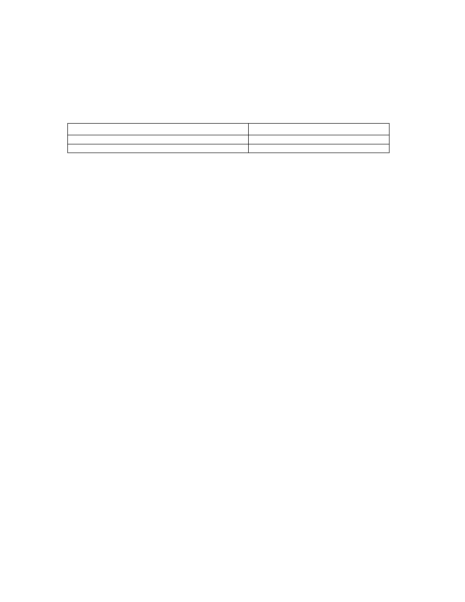
PostHASTE Post-Processor Formatting Reference Manual © 1989-2002 Paul Andrews & Ground Support
81
“M[Cool]”). Text variables may be simply output as 'free-standing' text (that is, without a letter in front of
it). In other words, you would NOT do this:
G{PartNo}
<< This is NO GOOD!
Examples
1. If you want a comment in your NC program that shows the name of the template file, you may include
one of these in your StartCode (or any other) sequence:
Sample template lines:
Sample output:
'(' {TemplateName} ')'
N20 (Fanuc 6T Generic)
'(' {TemplateName} {TemplateExt} ')'
N20 (Fanuc 6T Generic.pT2)
2. Text variables and/or numeric variables can also be used (with or without quoted phrases) to construct
file names in the File Alias command like this:
File ALIAS 1 {CLPath} 'YASDA\O' [Sub]+[Val6]
Note that you can use numeric variables (in the above example [Sub] and [Val6]), and you can even use
equations ([Sub]+[Val6]) when building the file alias.
7.3.4 Important information regarding text and text variables:
There is a wide range of things that you can do with text and text variables, as well as some capabilities and
limitations you need to know about.
See section 5.3.4 for more details on the File commands, including File Alias.
See section 9.1.1.6 (in Appendix A) for a list of all text variables.
7.4 “Search and Replace”
Lines like the following ones (which are used in some of the older Heidenhain 'conversational' formats) can
be added to the template to “Replace” certain phrases with others.
Replace 'G2 ' with 'DR-
replace "G3 " With 'DR+ '
REPLACE 'T' WITH "TOOL DEF "
Notice that both the phrase to be replaced AND the new phrase are enclosed in quotes. This is necessary in
order to be able to search and replace phrases with embedded spaces (such as “TOOL DEF”). Unlike most
other areas of the template, PHRASES WITHIN QUOTES ARE ALWAYS CASE SENSITIVE! So, don't
use “g3” when you really want to search for “G3”. (The words REPLACE and WITH, however can be
upper, lower, or any mixture of cases as in the example above.)
Also, if you were paying attention, you noticed that some of the phrases in the example above use 'single
quotes' and some used “double quotes”. This is fine as long as each phrase starts and ends with the same
kind of quote marks. See section 7.3.2 regarding use of quotes.

82
PostHASTE Post-Processor Reference Manual
© 1989-2002 Paul Andrews & Ground Support
How Search & Replace works
Each line of outgoing NC code will be scanned as many times as there are “Replace” lines in the machine
format, and if a “replace” phrase is found, it will be replaced ONLY ONCE (unless you use the ALL option
discussed below), then the post will go on to scan the same line again for the NEXT “Replacement”.
Example:
Using the Replace commands shown above, the line...
G2 T1 G2 X0
...would end up being output as:
DR- TOOL DEF 1 G2 X0
(Notice that the second G2 is NOT replaced because it was found [and replaced] earlier in the line.)
Since the search and replace happens on a “per line” basis, it CANNOT be used to replace end-of-line
characters, and cannot be used to “join” two lines into one. (To effectively 'join' two lines, see the NoEOL
command in section 5.3.5.)
Sometimes, “Search and replace” works TOO good... notice also, that spaces within the search phrase can
be used to prevent unwanted replacements. In the first example, if we had used a “G2” and “DR-“ (without
the trailing spaces), it would cause all “G28” words to end up as “DR-8” !
Avoid 'double-replacements'!
Also, if more than 1 “replace” line is used in a format, THEY ARE PERFORMED IN THE ORDER THAT
YOU SPECIFY THEM! This means that there is a possibility that you can inadvertently “double-replace”.
Example of 'double-replacement' (don't do this!):
If the following replace lines are used in this order...
REPLACE 'T' WITH 'TOOL DEF'
REPLACE 'D' WITH 'DIAM.'
...then the “D” in “TOOL DEF” will be replaced with “DIAM. “ and will cause “T1” to be changed to
“TOOL DIAM. EF 1” instead of “TOOL DEF 1”.
To prevent 'double-replacements' from happening, just reverse the order of the “Replace” lines so the D is
replaced BEFORE the T.
NOTES:
Limits are not checked on phrases that are the result of a “Replace” statement. In other words, if you
inadvertently replace a phrase with another that is beyond a particular limit, then no warning will
appear.
The size of the “Search phrases” (the 1
st
quoted phrase in a “Replace” line) is limited to 16 characters,
and the “Replace” phrase (the 2
nd
quoted phrase per line) is limited to 70 characters.
The NoComment option
If you want to prevent a 'replacement' from occurring within program comments, then add the word
NoComment to the end of the Replace line like this:
Replace 'A' with 'A-' NoComments

PostHASTE Post-Processor Formatting Reference Manual © 1989-2002 Paul Andrews & Ground Support
83
Notes re NoComment:
- You may use either NoComment or NoCommentS: the post will figure it out either way.
- Reminder: As always, the Replace command (still) only acts ONCE per line.
- The NoComment option will only prevent the FIRST comment on the line from having a 'replace'
performed. In other words, if there is MORE THAN ONE COMMENT on the line, the second
comment will not be 'protected' from the replace. (This shouldn't raise any problems; I can't remember
the last time I saw a line of code with more than one comment on it...)
- The NoComment option may be used in conjunction with the All option below. (The options may be
listed in either order.)
The ALL option
Unless you use the All option, a Replace command is only performed once per line of output. This means
that if you have more than one occurrence per line of something that needs to be replaced, just add the
word ALL to the end of the Replace line like this:
Replace '_' with ' ' All
As mentioned above, the All option may be used in conjunction with the NoComment option like this:
Replace ',' with ', ' All NoComments
Or:
Replace 'X' with 'X-' NoComments All
NOTE: Since the All option causes the replacement process to repeat until all occurrences are replaced, be
careful not to create an 'infinite loop' with your Replace...All commands. This happens when your 'new'
phrase contains the 'old' phrase like this...
Replace '99' with '999' All
... 99 becomes 999, which gets 'replaced' again and becomes 9999, then 99999, then 999999, etc. ad
infinitum.
If left unchecked, this would continue until all memory and disk space have been consumed, followed by a
crash of your PC's operating system. (Suffice it to say that infinite loops are a bad thing...)
Fortunately, we limit the post's 'replace... all' to 100 repetitions – more than enough to get your job done,
but far less than would ever cause any problems on your computer. PostHaste gives you a warning (and
then aborts) if a Replace is repeated more than 100 times on any line of code.

84
PostHASTE Post-Processor Reference Manual
© 1989-2002 Paul Andrews & Ground Support
7.5 If / Else Logic
IF, ELSE and ENDIF statements can be used to cause PostHaste to either allow or disallow any lines in any
sequence based on the mathematical relationship between any 2 variables and/or constant values.
Here's a sample of a ToolChange sequence that uses if/then logic in 2 different places - first, to control
dual-range spindle speed (M41, M42), then again to suppress the “pre-indexing” in the last tool change.
(blank lines have been added for clarity to separate the "logic" sections from the rest of the sequence):
ToolChange
M9
G28 G49 Z0 S100
N[Block] M6
This 'IF' structure sets the 'gear range' (M41 or 42):
if [Speed] > 500
G0 G40 G80 G[Work] X[H] Y[V] M42
else
G0 G40 G80 G[Work] X[H] Y[V] M41
endif
G43 Z[D] H[Lcomp] M[Direct] S[Speed]
M[Cool]
This one suppresses pre-indexing of the last Tool:
if [NextTool] <> [Tool1]
T[NextTool]
endif
End
...as you can see from the example above…
• either one or both of the 2 values on the if line must be a [variable]. It can even be a variable that is
set from an ASK statement - letting you give the operator a set of processing "options"... let your
imagination run wild!
• The lines 'inside' the IF structure may be indented. (Note: They may be indented one space only! If
more than one leading space is used, that line will become a 'comment' - ignored by PostHaste!)
Here are the actual “rules” that apply to the if / then logic:
The IF line must have a variable or a number followed by a 1 or 2-character “logical operator”, then
another variable or number. As usual, all items must be separated by a single space. The optional Else line
and the required Endif line do not use any "parameters". Here are some sample "If" lines:
IF [Val1] = 2
If [Tool] > 24
if [speed] <= 500
(Note: Just as with all variable, sequence and command names, please notice that the capitalization of the
words If, Else and EndIf doesn't matter.)

PostHASTE Post-Processor Formatting Reference Manual © 1989-2002 Paul Andrews & Ground Support
85
Logical operators ('Equals', 'Greater than', etc.)
This is a list of the legal logical operators that can be used on the if line:
Operator Meaning
>
“Greater
than”
<
“Less
Than”
=
“Equals”
<>
“does
not equal”
<=
“is less than or equal to”
>=
“is greater than or equal to”
Other limitations that apply to the use of logic:
• IF can only be used within a sequence or canned cycle.
• An ENDIF line is required (even if there are no more lines after ENDIF within that sequence).
• The ELSE line is optional.
• The IF, ELSE and ENDIF lines must have at least 1 line of "code" between them.
• IF statements cannot be nested.
• You are limited to 100 IF structures per template.
Testing 2 conditions: Using AND and OR with IF
You can use the words AND and OR to make an IF function test for 2 conditions at a time as in the
following examples:
if [Tool] > 5 OR [Val1] = 1
...do these lines...
ENDIF
if [LastHole] <> 1 AND [SpeedType] < 97
...do these lines...
ENDIF
7.6 Outputting subs (subprograms), and the
automatic 'multiple part' program feature
PostHaste can output NC program subroutines or subprograms (we will refer to these as 'subs'...) for either
of two reasons:
1. To automatically create subs to achieve 'multiple-part programs'
(where each tool's motion is put into a separate sub, and then the 'main' program consists of tool
changes and sub calls), or
2. If your incoming CL data includes subs, and you simply want the post to output them accordingly.

86
PostHASTE Post-Processor Reference Manual
© 1989-2002 Paul Andrews & Ground Support
7.6.1 Basic Fanuc setup example
In either of the above cases, setting up your template to output subprograms or subroutines (commonly
referred to as “subs”) is usually quite simple. (We also give you ways to handle quite a few variations from
the 'basic' setup shown in this example.) However, before getting into all of the details, here is an example
showing what you would add to a typical Fanuc post template to add sub support.
Just add the SubCall, SubStart and SubEnd sequences (and make sure the letters you need are formatted in
the 'letter format' section of your template):
SubCall
Describes the code used to call subs from the 'main' program.
G0 G[Work] X[H] Y[V]
Z[D]
M98 P[Sub]
end
SubStart
The code that appears at the top of each sub.
O[Sub]
G0 X[H] Y[V]
End
SubEnd
The code at the end of each sub.
M99
End
Between
C
ode 'between' the last sub and the start of the 'main program' portion of the file.
O[Program#]
(See note below)
End
... that's all you have to do! PostHaste will apply these sequences whenever they are needed in the code to
output your subs properly.
Note: By default, PostHaste will output the subs before the main portion of the program. If you want the
subs to be output after the main portion, use the Subs1st? switch (discussed below).
7.6.2 Automatic multiple part programs
This is an exceptionally useful feature of PostHaste, as many CAM systems do not do a good job of
producing compact NC programs for 'multiple part' setups... PostHaste will do it for you.
If your template contains the above sequences, PostHaste will automatically generate a multiple part
program if there are no subs found in the CL file.
When PostHaste creates a multiple part program, it creates a sub for each tool's motion. Therefore if your
job uses 9 tools, there will be 9 subs generated. (If any tool is repeated later in the job, another sub will be
made for that section of the program as well.) PostHaste then produces a 'main' program that (after each
tool change) calls the tool's corresponding sub at each work offset. The number of work offsets will
match the number of parts. This is an important point, because you are limited to the number of parts
by the number of work offsets that are available on the machine.
When a multiple part program is being generated, the post will ask you the following questions:
• “How many parts are there?”
Remember - you are limited by the number of available work offsets.

PostHASTE Post-Processor Formatting Reference Manual © 1989-2002 Paul Andrews & Ground Support
87
• “What is the first work offset number?”
Work offsets will 'increment up by one' for each part. If you indicate 54 as your first offset, the first
part will be G54, the second part will be G55, and so on. (You may use G55 or G56 [etc.] as the
'first' offset if you like - but just remember that by doing so, you are reducing the total number of
parts you can cut because of the 'upper limit' of you available work offsets.)
• “Do you want to 'reverse' the order of the offsets for each tool?”
On setups where several parts are spread out over the length of a machine table, there is less rapid
motion required if you 'reverse' the order of the offsets. For example, the first tool would work in
the order from G54 to G59 (e.g. 'left to right'), then the second tool would start with G59 and work
back to G54 (working from right to left). This feature eliminates the 'long' rapid moves from
one end of the table to the other after each tool change, and thus reduces the overall cycle
time on the job. (The time savings are especially noticeable on jobs with 'low cutting time per tool'
and a relatively large number of tools.)
7.6.2.1 Sub
numbering
For multiple part programs, the [Sub] number (the 'O' number at the start of the subs) is automatically
incremented (starting at 1) each time a new sub is output. It is usually a good idea to 'add' the sub numbers
to the [Program#] variable so that the subs will follow directly after your main program in the machine's
'directory' page. In other words, if your 'main' program number ([Program#]) is 2000, you would want the
first sub to be 2001, the second 2002, etc. To do this, simply add the [Program#] to the [Sub] in your
SubStart and SubCall sequences as shown here:
SubCall
Describes the code used to call subs from the 'main' program.
G0 G[Work] X[H] Y[V]
M98 P[Sub]+[Program#]
end
SubStart
The code that appears at the top of each sub.
O[Sub]+[Program#]
G0 X[H] Y[V]
End
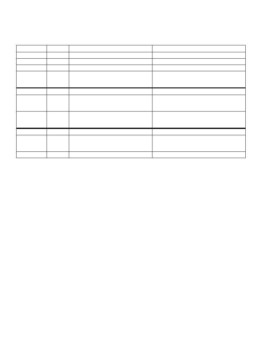
88
PostHASTE Post-Processor Reference Manual
© 1989-2002 Paul Andrews & Ground Support
7.6.3 Sequences, variables and switches used for subs
The output of all code related to subs is controlled in the template by using the items in the table below.
This table describes them briefly, and details follow in the next sections.
Items:
Type:
Notes / Description:
Mandatory (for subs to be output properly)?
SubStart Sequence Code output at the start of each sub.
Yes
SubEnd
Sequence Code output at the end of each sub.
Yes
SubCall
Sequence Code required to call a sub.
Yes
Between
Sequence Describes any code that needs to be output
between the 'main' portion of the program and
the subs.
No. (Only used for machines that require some
special code to separate the 'main' portion of the
program file from the 'subs' portion.)
[Sub]
Variable
Outputs the “O” number of the sub.
Either [Sub] or [SubLine] must be used.
[SubLine]
Variable
Outputs the number of the N word (line
number) of the sub. See section 7.6.3.3 for
details.
Either [Sub] or [SubLine] must be used.
[Times]
Variable
Usually the L number on the M98 (sub call) line
in Fanuc programs. See section 7.6.3.3 for
details
Not needed if you are only using subs for multi-part
formats. This is needed if the CL data ever
indicates that a sub is to be repeated.
RenumSubs?
Switch
See explanation below in section 7.6.3.4
No (N is the default condition)
SpliceSubs?
Switch
Set this switch to 'N' if you want the subs to be
output in a separate file (or files) from the main
program. See section 0 for details
No (Y is the default condition)
Subs1st?
Switch
See explanation below in section 7.6.3.4
No (N is the default condition)
7.6.3.1 SubCall sequence
The SubCall sequence shows how the subs will be called from the “Main” portion of the NC program. (See
the 'basic' example in section 7.6.1 above.)
SubCall
Describes the code used to call subs from the 'main' program.
G0 G[Work] X[H] Y[V]
M98 P[Sub]+[Program#]
end
7.6.3.2 SubStart,
SubEnd, and Between sequences
The SubStart and SubEnd sequences are used to describe how the subs start and end, respectively - as
shown in the example above.
The Between sequence is used to describe any special code that should go between the subs and the main
program code (Use the Subs1st? switch [see below] to direct PostHASTE to put the subs either before or
after the “main” portion of the program).
Example:
These sequences and switches (in addition to the SubCall, SubStart and SubEnd sequences in the example
above) are used for some Fadal formats...
Subs1st? Y
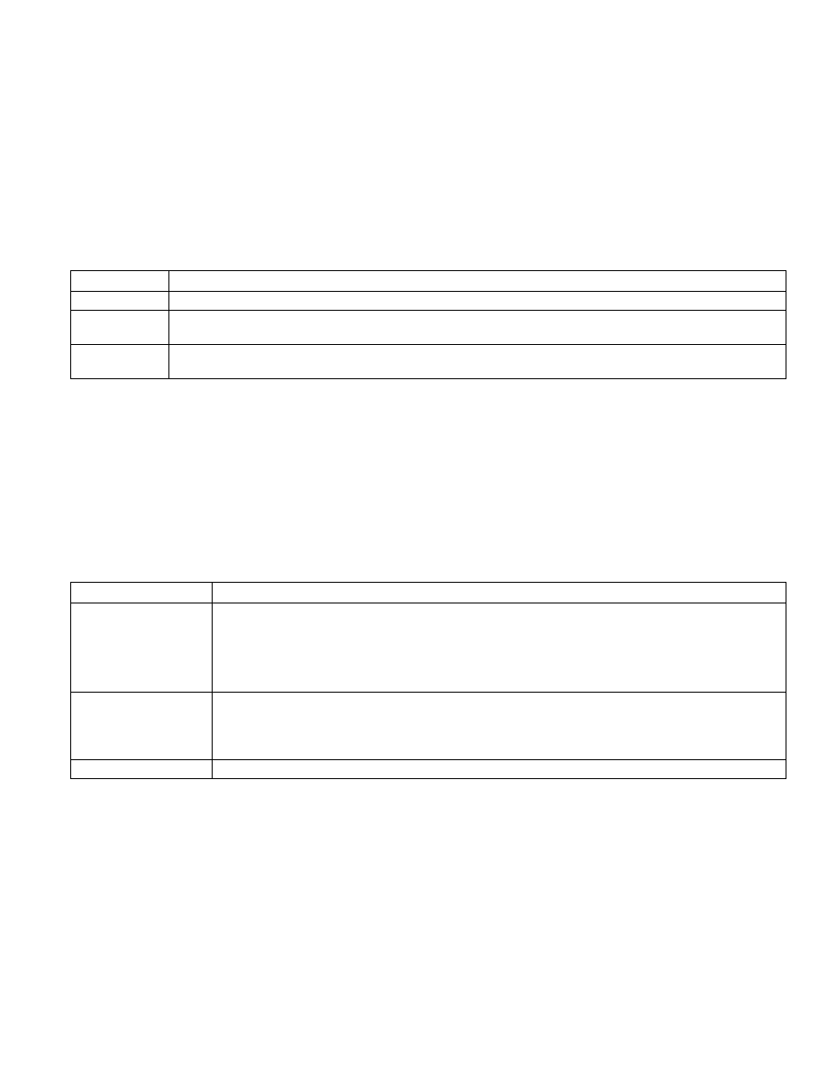
PostHASTE Post-Processor Formatting Reference Manual © 1989-2002 Paul Andrews & Ground Support
89
Between
M17
M30
End
...because some Fadal machines require that the subroutines come before the main program and that there is
a M30 between the 'subs' and the 'main'.
7.6.3.3
[Sub], [SubLine] and [Times] (sub variables)
The following variables give you control of formatting of NC programs using Sub-routines & Sub-
programs:
The variables: What they do:
[Sub]
This is the value of the sub number, and can be used in the SubStart and SubCall sequences as in the above examples.
[SubLine]
This is used in the SubCall sequence in place of [Sub] to call a sub by its “line” (sequence) or “N” number (as opposed to
using the sub number itself).
[Times]
This is used to designate the number of times a sub repeats. This should only be used in the SubCall sequence as shown
above.
Here's an example of how you would use the [SubLine] and [Times] variables in your SubCall sequence:
SubCall
M98 P[SubLine] L[Times]
end
7.6.3.4
Switches used to control subs
Here are more details on the formatting switches have been added to help you control other actions that are
significant when using subs:
Formatting switches: What they do:
RenumSubs? Y
Use this line to indicate that you want the sequence (N) numbers to be reset at the beginning of each sub and at
the start of the “main” program section. You may also use an N to prevent this action.
Notes:
1. If this line is not used, then the default condition is not to restart the numbers (as if you used the N option).
2. Do NOT attempt to use the Y option if you are using the [SubLine] variable (discussed above).
Subs1st? N
Use this line to indicate that you want the subs to be placed after the main portion of the program - change the N
to Y to output the subs before the main program.
NOTE: If this line is not used, then the default condition is to place the subs before the main portion of the
program (as if you had used the Y option).
SpliceSubs? N
See below...
SpliceSubs? switch
This switch can be used to tell the post to NOT include any subroutines in the main NC program file.
Typically, when subroutines are used, PostHaste includes them in the main output (.NCC) file. To do so, it
first writes the NC code contained in each sub into a temporary file - one for each sub - then when all of the
code (for subs and the 'main' program) has been generated, PostHaste automatically 'splices' all of those
temporary files together to form the final output file. If you do NOT want the subs to be 'spliced' together
with the main program, use this switch setting to prevent it:
SpliceSubs? N

90
PostHASTE Post-Processor Reference Manual
© 1989-2002 Paul Andrews & Ground Support
The most common reason you would use this is if you want each sub (or all subs) to be output to it's own
separate file (instead of into the main file). In order to do this, you would need to use File commands to
control the output of the various 'subs' and 'main' portions of your code into the files of your choice. Here is
an example of one way you could do this:
SpliceSubs? N
Do NOT splice the subs into the main file because each sub is
put into in separate file (example: MyPart-SUB2.DAT ).
SubCall
File on Main only
M98 'P' {CLName} '-SUB' [Sub]
<< ...each sub is called by the FILE NAME of the sub (less the '.DAT').
end
SubStart
File alias 1 {CLName} '-SUB' [Sub] '.DAT'
<< Each sub file name based on the CL name and sub #.
File empty 1
File on 1 only
<< (Each sub is written into the file named above on the File alias line.)
end
SubEnd
M99
File on Main only
<< After each sub is completely written, make sure that you go back to writing to the main file.
end
NOTE: Be careful using this switch! If you tell the post...
SpliceSubs? N
...without properly routing the subs into the files you want (by using the File commands as demonstrated in
the above example), then your subroutines will simply not exist in the final NC program!
For more information on subroutines (including automatic generation of multiple-part programs) see
section 7.6.
For more information on use of the File commands, see section 5.3.4.
7.7 The PostHaste.log file (for “debugging”)
PostHaste generates the PostHaste.LOG file (in the same folder as your PostHaste.exe file). This file is a
"debugging" aid that is essentially a "merging" of the incoming CL data and the outgoing NC code. By
looking at this file (in any text editor), you can see exactly which CL records produced each line of NC
program. (The incoming CL lines are numbered for your convenience.) NOTE: This file is overwritten each
time you run the post, so if you want to save it, you will either have to rename it or move it to another
folder.
The example below is an excerpt from a PostHASTE.LOG file. For your convenience, the incoming CL
lines are numbered and a blank line is placed at the end of each section of NC code that is output. This
visually 'groups' the code with the CL data that produced it. (Note: Shading has been added to this
document to highlight the first few sections of NC code - shading will not appear in an actual
PostHASTE.LOG file.

PostHASTE Post-Processor Formatting Reference Manual © 1989-2002 Paul Andrews & Ground Support
91
### This is the .LOG file produced during processing of c:\temp\drill.ncc.
### This file lists the CL data and the NC program data produced by it.
### (This file gets overwritten each time you run the post.)
O1
G20 G90
3 >PARTNO / 1050-2207_WP
5 >MACHIN / MILL, 01
6 >UNITS / INCHES
7 >LOADTL / 5
11 >SPINDL / RPM, 500.00, CLW
12 >FEDRAT / 100.00, IPM
13 >GOTO / 0.00, 0.471000, 0.500000
G70 G50 G19 H0 M9
T5
G0 G32
G40 G80 M5 M9
M6
S500 M3
G0 X0 Y0.471
M9
D5 G43 H5
Z0.5
14 >CYCLE / DRILL, DEPTH, 0.093000, IPM, 5.00, CLEAR, 0.10
15 >GOTO / 0.00, 0.471000, 0.400000
G81 F5. R0.5 Z-0.193 G98
G0 X0 Y0.471
16 >CYCLE / OFF
G80
…
…
64 >FEDRAT / 100.00, IPM
65 >GOTO / -1.00, 0.906000, 1.125000
G1 F100. Y0.906
66 >SPINDL / OFF
69 >LOADTL / 6
74 >SPINDL / RPM, 500.00, CLW
75 >FEDRAT / 300.00, IPM
76 >GOTO / -1.205000, 0.00, 0.800000
G70 G50 G19 H0
T6
G0 G32
G40 G80 M5 M9
M6S500 M3
G0 X-1.205 Y0
M9
D6 G43 H6
Z0.8
78 >CYCLE / BRKCHP, DEPTH, 0.137940, STEP, 0.030000, $
IPM, 1.00, CLEAR, 0.00, RETURN, 0.50, $
DWELL, 1.00, TIMES, 1
79 >GOTO / -1.205000, 0.00, 0.400000
G73 F1. Q0.03 D0.05 V-0.03 R0.4 Z-0.1379 G98
G0 X-1.205 Y0
80 >GOTO / -1.00, 0.471000, 0.400000
X-1. Y0.471 Z0.2621
81 >GOTO / 0.00, 0.471000, 0.400000
X0
…
…
86 >GOTO / -1.00, -0.471000, 0.400000
X-1.
87 >CYCLE / OFF
G80
88 >FEDRAT / 300.00, IPM
89 >GOTO / -1.00, -0.471000, 0.450000
G1 F300. Z0.45
90 >SPINDL / OFF
92 >FINI
G31
M30
This file is overwritten each time you run the post, so if you want to save it, you will either have to rename
it or move it to another folder.
“F.Y.I.” - Looking at the beginning of this log file also tells you two important things about how PostHaste
works:
1. The StartCode (in this case, the first 2 lines of NC code) is always generated before any CL data is read.
2. The 1stToolChange sequence is always “triggered” by the first GOTO in the CL data.
Inhibiting the log file for faster processing.
If you need to process long jobs, inhibiting the automatic generation of the .log file may help the post run
slightly faster when processing. If you would like to inhibit this feature, add the following line to your
PostHaste.CFG file:
Logging? N
The “N” (no) tells the post to NOT create a PostHaste.LOG file. If this line is omitted (or if you use “Y”),
then the post WILL create a PostHaste.LOG file (the equivalent of “Logging? Y”).

92
PostHASTE Post-Processor Reference Manual
© 1989-2002 Paul Andrews & Ground Support

PostHASTE Post-Processor Formatting Reference Manual © 1989-2002 Paul Andrews & Ground Support
93
8. “Special Case” Tactics & Notes
This section of the manual covers some tactics that you can use to achieve NC code output to match some
special cases that we've come across over the years. This section is by no means an exhaustive reference of
all the things you can achieve, because the only limits are your imagination. This section is meant to help
stimulate your imagination by giving a few examples of how we've used some of the formatting “tools” in
the GS post to overcome some specific formatting problems.
8.1 Concerning incremental / absolute output and
the [IncMode] variable
The [IncMode] variable gives you a great deal of control over how the absolute/incremental codes are
placed in your NC programs. Instead of “hard coding” a G90 or G91 in any sequence, you can use
G[IncMode] . The difference is that when the tool motion file that comes from the CAM program
designates which parts of the tool motion are to be coded in incremental or absolute mode, PostHaste
automatically places the corresponding G code in the location you've specified with G[IncMode].
For the [IncMode] variable to work, the following line MUST be present in the template:
Inc/Abs G 91 90 ( Inc first, then Abs. )
If you don't have it, PostHaste will warn you to add it before it will process the tool motion.
You can use [IncMode] in any sequence. Here are 2 examples:
ToolChange
T[Tool] M6
G0 G[IncMode] X[H] Y[V] [----IncMode established at each
S[Speed] M[Direct] tool change...
G[43] Z[D] H[LComp]
End
Sub
O[Sub]
G[IncMode] [----IncMode established at each sub.
end
Note: A G90 or G91 (according to the Inc/Abs line as formatted above) will automatically appear in the NC
code whenever the mode is changed by information coming in from the tool motion file. This will NOT
happen if the [IncMode] variable is used as the “trigger” variable for an UPON sequence - because the post
expects you to have formatted your UPON sequence to handle it properly.

94
PostHASTE Post-Processor Reference Manual
© 1989-2002 Paul Andrews & Ground Support
8.2 How to format “P1=” type codes.
If you will recall, in the very first pages of the post-processor manual, it is clearly stated that PostHaste is
designed to output NC code such that EVERY “word” of the code is “a letter followed by a number”.
However, you can use the “replace” feature to overcome this limitation.
Here's a good example of a case where this can be done.
Some machines require drilling (and other) parameters to be output in a way that requires more than just “a
letter followed by a number”. For example, look at this peck drilling cycle:
G83 X1.0 Y2.0 P1=.5 P2=.25 ( P1 is the hole bottom Z, P2 is peck increment. )
To output this, use the following lines to your template:
Peck
G83 X[H] Y[V] a[D] b[Step]
end
replace 'a' with 'P1='
replace 'b' with 'P2='
Of course, you must make sure that the letters “a” and “b” have been formatted in the “letter format”
section of the file by using lines like these:
a >3.>4
b >3.>4
As you can see, the “replace” feature is limited only by your imagination. To see it in intensive use, look at
a “Heidenhain Conversational” format.

PostHASTE Post-Processor Formatting Reference Manual © 1989-2002 Paul Andrews & Ground Support
95
8.3 'Block deletes' on multi-part sub calls
In multi-part programs, it is helpful to have 'block delete' (/) characters on all sub calls except the ones
operating on the first fixture location. This way you can prove out a program on only 1 fixture (by turning
on your machine's block delete switch), then activate the other fixtures later by turning it off. Here's what
you may want such code may look (especially note the lines in bold)...
%
O1
T1 M6 ( T1 - SHELL MILL [NO COOLANT])
N1 G0 G40 G80 G90 G54 X7.25 Y5.
G43 H3 Z0.25 S8000 M3
G54 G0 X7.25 Y5.
M98 P2
/ G55 G0 X7.25 Y5.
(All offsets except G54 have block delete...)
/ M98 P2
/ G56 G0 X7.25 Y5.
/ M98 P2
/ G57 G0 X7.25 Y5.
/ M98 P2
M5
G91 G28 Z0 M9
T2 M6 ( T2 - SPOT DRILL)
N1 G0 G90 G57 X8. Y13.5
G43 H1 Z0.25 M8 S8000 M3
/ G57 G0 X8. Y13.5
/ M98 P3
/ G56 G0 X8. Y13.5
/ M98 P3
/ G55 G0 X8. Y13.5
/ M98 P3
G54 G0 X8. Y13.5
M98 P3
M5
...
If this is the kind of output that you want, then you may achieve it by simply using an IF condition:
SubCall
Describes the code used to call subs from the 'main' program.
IF [Work] = 54
G0 G[Work] X[H] Y[V]
M98 P[Sub]+[Program#]
ELSE
'/ ' G0 G[Work] X[H] Y[V]
'/ ' M98 P[Sub]+[Program#]
ENDIF
end
Please note the trailing space character inside the quotes. Remember - when text is output, the post does
NOT automatically pad it with spaces, as it does the actual output 'words' (such as G0 or X[H]) when the
"Spaces? Y" switch is used.
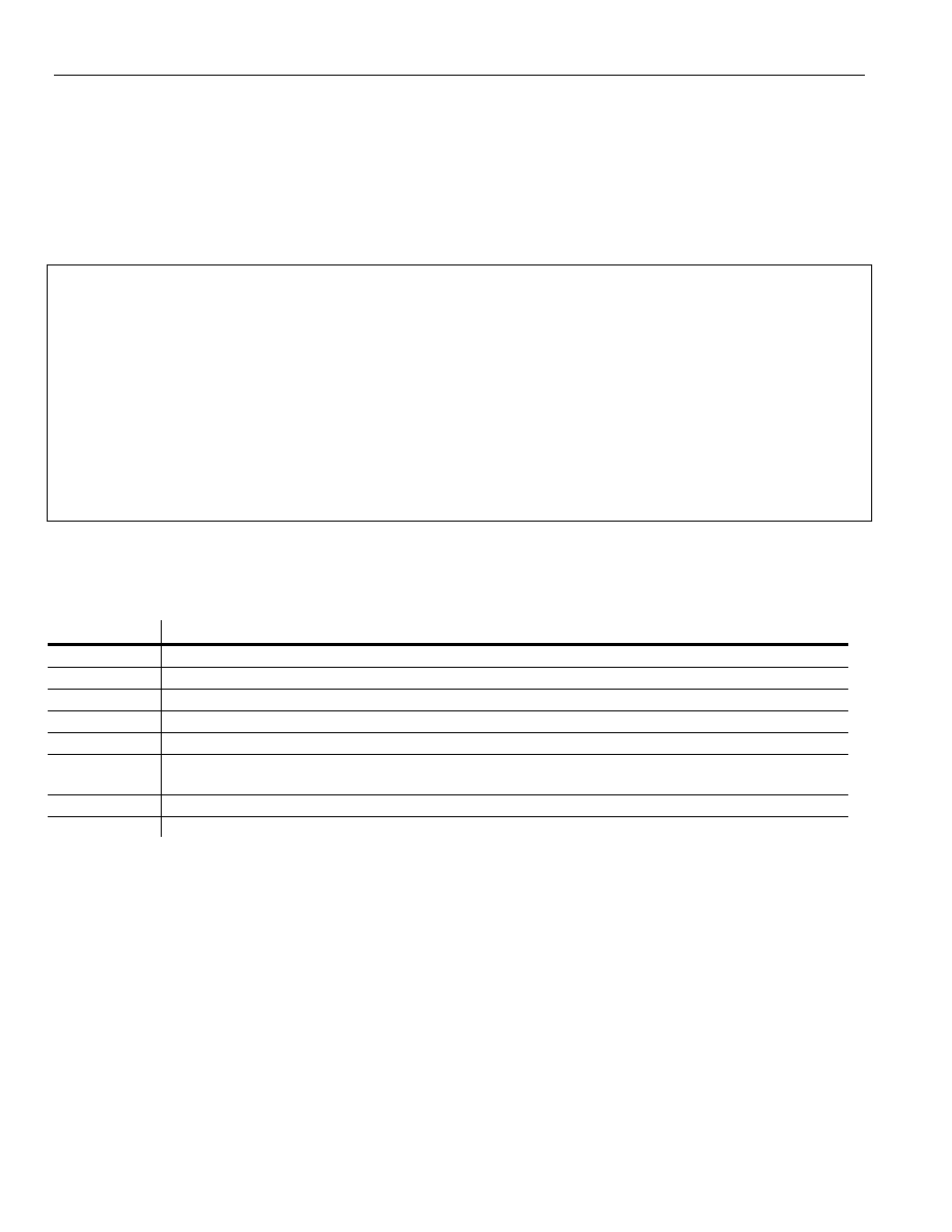
96
PostHASTE Post-Processor Reference Manual
© 1989-2002 Paul Andrews & Ground Support
9. Appendix A - List of Variables
Following are lists that describe all of the variables that you can use in the sequences. Because there are so
many types of values that can be used in a machine program there are several pages of variables listed here.
You certainly do not need to memorize all of the variables - they are here for your reference. (You may,
however want to just “skim” it to get an idea of what's available.)
NOTE: You may see other variables in your template that are not listed here. This could happen in one of 2
cases:
1. 'User-defined' variable names may have been created (using a Rename command - see section 4.1.26)
by the person who created or modified the template.
OR...
2.
We may have missed documenting some of them in this manual! (Sorry!)
SO... If you see a variable in your template that you don't recognize from the lists below, then first
check all of the Rename lines in the template. If there is NOT a matching Rename line, then that
means we missed documenting it! If this is the case, please notify us and we will make sure that it
is added to future revisions of this manual.
Categories of variables
In the lists of variables below, there is a Category column. This is what each category means:
Category Relevance
Axis position
These are the actual positions of the machines axes.
Motion attributes Various information about the movement (distance moved, feed rate, etc.)
Arc motion
Variables that are used only in processing arc motions.
Drilling
Variables that are used only in processing drilling ('point to point 'canned' cycles.
Tool Change
Information related to the tool change process, or attributes of the tool itself
Prompted
The values of these variables will be asked of the user when the post runs - they are generally NOT set by the
incoming CL data.
Subs
Variables used for calling and/or defining machine subroutines and/or subprograms.
General
Variables that don't fit into any of the above categories

PostHASTE Post-Processor Formatting Reference Manual © 1989-2002 Paul Andrews & Ground Support
97
The variables...
In addition to supplying 'categories', we have grouped the variables into separate lists according to the areas
of usage in the format. Generally, all of the variables in a list will be used in the same sequence (or related
sequences).
NOTE: Within each list, the variables are listed in alphabetical order.
NOTE:
Variables marked with asterisk (*) are probably not supported by your CAM system, so you should
generally avoid using them. (Although you may employ them as “general use” variables by setting their
values by using the Set command within the format.)

PostHASTE Post-Processor Formatting Reference Manual © 1989-2002 Paul Andrews & Ground Support
98
9.1.1.1
Variables that apply to movements in general
You can use these variables in any sequence that produces motion. (ToolChange, Index, RapidCode,
LineCode, CwCode, etc.)
Variable(s)
Category
Details
Related / similar items
AAxis, BAxis,
CAxis
Rotary
motion
The (angular) position for the rotary axes ON 5 (or more) AXIS POSTS.
(4 axis posts usually use RotAngle.)
RotAngle
Adir, Bdir,
Cdir
Rotary
motion
Typically only available on 5 (or more) axis Mill posts (or MillTurns with
more than 1 rotary axis). The direction (0 = no rotary motion, 1 = Ccw, 2 =
CW) that each rotary axis is moving on the current move (4 axis posts
usually use RotAxDir.) These directions follow the ISO standard for tool
rotation. (See the 5 axis Addendum manual for details on this.)
AAxis, BAxis, CAxis,
RotAxDir
ADist, BDist,
CDist
Rotary
motion
Typically only available on 5 (or more) axis Mill posts (or MillTurns with
more than 1 rotary axis). The distance (in degrees) each rotary axis is
moving on the current move (4 axis posts usually use Dist4.)
HDist, VDist, DDist, Dist4
CPref Rotary
motion
You may Set this variable to indicate the "preferred C value for the post to
output whenever the machine has to do a (relatively long) rapid move
(where the tool is moved into ‘'tool shank vertical’ [“I,J,K = 0,0,1”] position)
moves". This is only needed on machines with a C axis that has physical
limits; user should USUALLY set this to the 'mid-travel' value of his C
axis; this should minimize the occurence of ‘unwinds’ by setting the C axis
to its ‘middle of range’. (default 0) to allow user to set
Unwind sequence
D
Axis position “Depth” (Z) linear axis endpoint position of the current movement
H, V, LastH, LastV, LastD
Dist4 Motion
attributes
Similar to Hdist, Vdist and DDist, but this is the angular measurement of
the current rotary axis move (4 axis milling applications only).
HDist, VDist, DDist
DPM Motion
attributes
The “degrees per minute” feed rate (used in rotary axis milling only).
FRate, InvTime
FRate Motion
attributes
Feed rate value. This outputs in the proper units (IPM, IPR, MMPM,
Inverse time, etc.) as needed.
Plunge, FeedType, DPM,
InvTime
H
Axis position Horizontal (X) linear axis endpoint position of the current movement.
V, D, LastH, LastV, LastD
HCDC, VCDC Motion
attributes
"CDC" (cutter diameter compensation) vectors - used by some older
Cincinnati machines. NOTE: For these to be active, the CDC command
must first be specified in the “Commands & Switches” section of your
post. Example:
CDC P Q
IVect, JVect, KVect
H2, V2
Motion
attributes
(4 axis Wire EDM posts only:) These hold the X and Y positions of the
endpoint of the current movement (Rapid, feed or arc) for movements on
the secondary (auxilliary) plane.
H, V, Hctr2, VCtr2
HDist, VDist,
DDist
Motion
attributes
These variables hold the linear distances that each axis is to travel on the
current move. These are SIGNED (+ or -) values: if X is moving in the
negative direction, [HDist] will be a negative value.
Dist4, MoveLength
HVector,
VVector
Motion
attributes
These 2 values indicate the (vector) direction of the first completely
compensated cutting move. They are used on machines that do not have
“look ahead” ability to indicate which way the tool is going to go on the
move AFTER the infeed. You will notice that they are used on the
INFEED line of the Fanuc 3000C format.
InvTime Motion
attributes
The reciprocal of MoveTime - “Inverse time” is a method that many milling
machines equipped with rotary axes use to determine the actual feed
rate. For those machines, this value is used instead of FRate.
FRate variable, RotaryFeed
command
IVect, JVect,
KVect
Motion
attributes
The 3 components of the unitized vector that describes “3D offset” - used
only for machines that support this type of offset and where the incoming
tool motion (CL) file provides this information. The post will not output
these vectors automatically; the LineCode sequence is typically used to
output these values if the machine needs them - as in this example:
HCDC, VCDC,
NormH, NormV, NormD

PostHASTE Post-Processor Formatting Reference Manual © 1989-2002 Paul Andrews & Ground Support
99
Variable(s)
Category
Details
Related / similar items
LineCode
G1 X[H] Y[V] Z[D] I[IVect] J[JVect] K[KVect] F[Frate]
end
LastH, LastV,
LastD,
LastRotAng
Axis position These hold the H, V and D and rotary (milling 4th axis) values that were
previously output (typically the XYZ values of the endpoint of the
previous movement). In other words, these values typically indicate where
the tool is immediately before the current move is processed & output.
BUT THAT IS NOT ALWAYS THE CASE. READ THE IMPORTANT
INFORMATION BELOW REGARDING THE USE OF THESE
VARIABLES.
Beware outputting (and calculations using) [LastH],
[LastV] or [LastD]:
Since the value in [LastD] (for example) gets updated IMMEDIATELY
(to the current [D] value) upon [D] being output, you must check or
use [LastD] in any output BEFORE [D] IS OUTPUT!
This is why in the helical arc examples shown in section 4.2.7.1 we have
the K value on the line BEFORE the Z value. (If we put it after Z, then
[LastD] would have already been updated, and would be equal to [D].)
The same is true with the variables [LastH] and [LastV].
If you need to use the value of [Last_] variables in several places in a
sequence, then a way that you can get around this problem is to
'memorize' the [Last_] value into another variable, then use that variable
instead. Here's a good example - in this RapidCode sequence, we have
added 'Z safety logic' to help prevent crashes, so the first thing we do is
memorize the [LastD] value:
RapidCode
Set [Val1] to [LastD]
Memorize "From" & "to" Z val's
Set [Val2] to [D]
if [Val2] < [Val1] Going down?
G0 X[H] Y[V] XY first,
Z[D]
then Z.
endif
if [Val2] = [Val1] Same Z...
G0 X[H] Y[V] Z[D] Output XYZ together
endif
if [Val2] > [Val1] Going up:
G0 Z[D]
Z first,
X[H] Y[V]
then XY.
endif
end
H, V, D, RotAngle
MoveLength
Motion
attributes
This is the total distance from the start to the end of the current move,
measured "as the bird flies" (not around arcs). It is essentially the
hypotenuse of the "3D triangle" defined by the start and end points of the
current movement. (This is always a positive value.)
Hdist, Vdist, DDist
MoveTime Motion
attributes
The length of time (in minutes) that the machine should take to complete
the current movement. (Calculated by dividing MoveLength by the [IPM or
MMPM] feed rate.)
InvTime, MoveLength,
TotalCutTime, TotalCutDist
NormH,
NormV,
NormD
Motion
attributes
These variables define the 3D compensation vector used to indicate 3D
offset direction when machining a 3D surfaces. They are ONLY set when
they are read from the '3
rd
triplet' of GOTO records (after first being
IVect, JVect, KVect

100
PostHASTE Post-Processor Reference Manual
© 1989-2002 Paul Andrews & Ground Support
Variable(s)
Category
Details
Related / similar items
activated by a MODE or APPLY record like this):
MODE/3DCOMP,ON or APPLY/3DCOMP,ON
These variables can be used in the LineCode sequence like this:
LineCode
G1 X[H] Y[V] Z[D] I[NormH] J[NORMV] K[NORMD] F[Frate]
end
Pitch Drilling,
Threading
This is the reciprocal of the thread lead (1 / lead). Example: for a 1/4-20
thread, the lead is .05, so [Pitch] = 20 (which is 1/.05). It gets set during
TAP cycles or when reading THREAD information from the CL file.
PolarAngle Motion
attributes
(Typically used for MillTurn machines when milling on the face of the
part…) This is the (typically C axis) angle of the current move’s endpoint
(with 0 degrees being along the X+ axis direction). This is almost always
used in conjunction with the PolarDist variable like this:
if [Mode] = 3 and [IVect] < .99
Face
(Polar) Milling:
G1 X[PolarDist] Z[D] C[PolarAngle] F[Frate]
endif
HOWEVER, you may use PolarDist and PolarAngle whenever you need
to output the ‘polar’ location of the current move’s endpoint (or the current
hole lcation, in the case of drilling cycles);
PolarDist will indicate the distance of the current endpoint from the origin,
and
PolarAngle will be the angle (measured in ‘CAD standard’ method: 0
degrees is “3 o’clock”…)
PolarDist, PolarBreak
PolarBreak Motion
attributes
On MillTurn machines, when this variable is set to a non-zero number, the
post will break lines and arcs that are milled on the 'face' of the workpiece
(typically in the XY plane) into short linear polar (typically X,C) moves.
This allows milling on the face of parts on MillTurn machines that do not
have a Y axis. If this is what you want to do, then Set [PolarBreak] to the
'chordal deviation tolerance' that you want to hold on face contour milling
operations.
MaxRad command,
PolarDist and PolarAngle
variables
PolarDist Motion
attributes
Almost always used in conjunction with PolarAngle – see discussion re
PolarAngle above.
PolarAngle, PolarBreak
RotAngle
Axis position The (angular) position for the milling rotary axis ON 4 AXIS MILLS ONLY.
(5 axis posts MUST use AAxis, BAxis and/or CAxis instead!)
LastRotAng,
AAxis, BAxis, CAxis
RotAxDir Motion
attributes
Set to 1 when the milling rotary table is to move counterclockwise, and -1
when clockwise.
RotAngle, Adir, Bdir, CDir
V
Axis position Vertical (Y) linear axis endpoint dimension...
H, D, LastH, LastV, LastD
RLevel Motion
Attributes
Vertical clearance: the lowest of the two rapid levels. (Usually the R value
in a canned cycle - mill only.)
TotalCutDist
Motion
Attributes
This is an ESTIMATE of the total distance the tool has traveled (so far)
while in FEED mode. (Not rapid.) This is typically used in the EndCode
sequence to display the overall estimated CUTTING (not including rapid)
time as in this example:
EndCode
M30
%0
'(EST._FEED_TIME:_' t[TotalCutTime] '_MIN._[' t[TotalCutDist] '_IN.])'
End
TotalCutTime, MoveLength,
FileSize
TotalCutTime Motion
Attributes
This is an ESTIMATE of the total TIME (in minutes) that the tool has
spent (so far) while in FEED mode. (Does not include rapid moves.) See
usage example immediately above.
TotalCutDist, MoveTime,
FileSize

PostHASTE Post-Processor Formatting Reference Manual © 1989-2002 Paul Andrews & Ground Support
101
9.1.1.2 Variables
that
can be used to format arc movements
These variables are only used in the ArcCode sequence. (Note - in older posts, there may be CwCode and
CcwCode sequences instead of a single ArcCode sequence.
Variable(s) Category
Details
Related / similar items
ArcDir
Arc motion
The “Direction numnber” of the arc. The number is set with the CW and
CCW commands. For instance, if you have the following CW and CCW
commands in your template…
Cw G2
Ccw G3
…then [ArcDir] will be 2 for clockwise arcs, and 3 for counter-clockwise.
ArcDir is typically used with the letter G (in the ArcCode sequence) like
this:
Ccw G[ArcDir] X[H] Y[V] …
All other variables in this
chart.
ArcPlane
Arc motion
See the discussion of the ArcPlane command in section 4.2.1
ArcPlane command
ArcRad
Arc motion
The radius of the arc.
All other variables in this
chart.
ArcStartH,
ArcStartV
Arc motion
These variables hold the horizontal and vertical coordinates, respectively,
of the start point of the current arc.
H, V
EndAng
Arc motion
See discussion of StartAng below. StartAng
HCtr, VCtr,
DCtr
Arc motion
Absolute (X,Y,Z respectively) location of the arc center.
All other variables in this
chart.
HCtr2, VCtr2 Arc motion
Absolute location of the arc center – for arcs on the ‘auxilliary’ (or
secondary) plane.
HCtr, VCtr, H2, V2
Ival, Jval
Arc motion
The I and J values for the arc center. These will be either absolute or
incremental (from the arc startpoint) depending on the CtrIncremental?
switch setting.
HCtr, VCtr
Normal1,
Normal2,
Normal3
Arc motion
These variables hold the X, Y and Z components (respectively) for the
“normal” vector of the most current arc. This vector describes the ‘axle’ of
the arc and is usually set to 0,0,1 for Counter Clockwise arcs and 0,0,-1
for Clockwose. (Note - Unigraphics posts are exactly the opposite. See
the Unigraphics? switch.)
IVect, JVect, KVect
StartAng,
EndAng
Arc motion
Ouputs the starting and ending angles of the current arc. (Angles will be
in the range of 0 to 359.999, with “3 o'clock being 0 degrees, positive
angles going ccw.)
All other variables in this
chart.
Sweep
Arc motion
This is used to output the span of an arc (measured in degrees). This can
be done by including it in the ArcCode (or CWCODE and CCWCODE)
sequences (see below). The value output will be negative (-) for
Clockwise arcs, and positive (+) for Counter-clockwise arcs. Therefore, if
you need the output value to always be positive, then make sure that the
letter you use it with is formatted with no minus sign (-). (Likewise, if you
need to reverse the sign so that CW arcs are positive sweep and CCW
are negative, then use the MULT modifier to multiply the letter's value by
negative 1.)
All other variables in this
chart.

102
PostHASTE Post-Processor Reference Manual
© 1989-2002 Paul Andrews & Ground Support
9.1.1.3 Variables
related to “point-to-point” Drilling cycles
Some of the sequences that these variables are used in are Drill, Peck, Tap, etc.
Variable(s) Category
Details
Related / similar items
Cycle
Drilling
See discussion of this in section 9.1.1.4 – as this variable is normally
used in ToolChange and 1st ToolChange sequences.
Tap
Dwell
General
Dwell time (measured in seconds) at the bottom of a hole.
LastHole
Drilling
This variable is automatically set to 1 when processing the last hole (and
ONLY the last hole) in a point-to-point sequence. It is usually used in an
IF statement to add or remove certain codes when processing the last
hole of a drill cycle.
The following example shows how to use LastHole in an IF structure (see
"If/Then Logic") to get a special code (in this case "G98") on the last hole.
Drill 5 (first 5 lines are for the 1
st
hole in the cycle)
if [LastHole] = 1
G81 G98 X[H] Y[V] Z[D] R[RLevel] F[FRate]
else
G81 X[H] Y[V] Z[D] R[RLevel] F[FRate]
endif
if [LastHole] = 1
X[H] Y[V] G98
else
X[H] Y[V]
endif
end cancel
[Rigid]
Orient
Drilling
[Orient] will be set to 1 when the CL file’s CYCLE record (describing the
current drilling cycle) includes the minor word ‘ORIENT’ (otherwise
[Orient] will be 0.)
[Rigid], [Orient]
PeckClear
Drilling
This is the “hole bottom clearance” distance that the post will use when
generating peck drilling cycles. The default value is .050” unless the
AskPeckClear? switch is set to Y (or if you use a Set command to set it to
another value). Example - for metric posts we recommend:
Set [PeckClear] to 1
AskPeckClear? switch (see
section 4.1.2 )
Pitch
Drilling
This is the reciprocal of the thread lead (1 / [Step]). Example: for a 1/4-20
thread, the lead is .05, so [Pitch] = 20 (which is 1/.05).
Note; To use [Pitch], a FeedType command must be used earlier in the
template.
[Step]
PointH,
PointV,
PointD
Drilling
Most drilling Canned cycles require a Z value indicating the absolute Z
position of the BOTTOM of the hole. That is why you usually see a Z[D]
word in most Canned cycle descriptions. Some machines, however,
require the designation of the Z level at TOP of the hole (the SURFACE
of the part), rather than at the hole bottom. For those machines, use the
PointD (“Point Depth”) variable instead.
PointH and Point V are useful in 5 axis posts if you need to designate the
XY location of the top of the hole.
[H], [V], [D]
RetPlane
Drilling
The value of the return plane mode (Initial plane = G98,“Rapid plane” =
G99.) The actual number output depends on the “ReturnPlane” command
(read about it in the Commands & Switches section earlier).
Rigid
Tapping
[Rigid] is set to 1 when the cycle being processed is a rigid tap cycle. You
may use an IF structure to output your TAP or Cancel sequences
accordingly. Examples:
Tap 6
[LastHole]

PostHASTE Post-Processor Formatting Reference Manual © 1989-2002 Paul Andrews & Ground Support
103
Variable(s) Category
Details
Related / similar items
If [Rigid] > 0
G93
G84 X[H] Y[V] Z[D] K[VBite] R[RLevel] F[FRate]
else
G84 X[H] Y[V] Z[D] R[RLevel] F[FRate]
endif
X[H] Y[V] W[RPlane]
end cancel
Cancel
G80
if [Rigid] > 0
G94
endif
end
Note: Since [Rigid] is not reset until the start of the next cycle, it can be
used in the CANCEL sequence as well as the TAP sequence.
Step Drilling For PECK cycle: the “pecking” value (mill only; lathe uses SBite)
For TAP cycle: the thread “lead” (the distance from one thread peak to
the next). Note that [Step] is the reciprocal of [Pitch]; e.g. for a ¼-20
thread ([Pitch] = 20), the [Step] value is .05 (which is 1/20)
[Pitch]
Tap
Drilling
See discussion of this in section 9.1.1.4 – as this is normally used in
ToolChange and 1st ToolChange sequences.
Tap

104
PostHASTE Post-Processor Reference Manual
© 1989-2002 Paul Andrews & Ground Support
9.1.1.4 Variables set from the Tool or Tool Change information
These variables are typically used in the ToolChange and 1stToolChange sequences. Some of them are
used other places as well.
Remenber - variables marked with asterisk (*) are probably not supported by your CAM system, so you
should generally avoid using them. (Although you may employ them as “general use” variables by setting
their values by using the Set command within the template.)
Variable(s) Category
Details
Related / similar items
(variables, unless noted)
Comp
Tool change info
Lathe Tool compensation offset #. (Not used for milling posts.)
LComp, DComp
Cool
Tool change info
Coolant M code value (on, off, mist). Typically M8, M9 and M7,
respectively
Corner *
Tool change info
The “corner radius” of the tool.
ToolRad, ToolDiam
Cycle
Tool change info
The [Cycle] variable gets set - when there is a holemaking or
threading cycle upcoming - according to the cycle type. Unless
noted, the values listed below are for posts running in MILL
mode. ADD 100 when post is in TURN (Lathe) mode:
Note that [Cycle] is set to 0 when 'milling' (In other words, NOT
doing any drilling cycles), and 100 when in 'turning' mode (e.g.
turning or grooving).
(Lathe) threading = 107
Drill = 13 (Remember: add 100 if in lathe mode...)
LTap = 14
Peck = 15
Tap = 16
Ream = 17
Bore = 18
Back = 19
Custom1 = 21
Custom2 = 22
Custom3 = 23
ChipBreak = 28
CSink = 29
(Please note that there are 'gaps' in the numbering sequence
above.)
SO... If you want to differentiate between MILL and DRILL cycles
in a mill post you would do something like this...
ToolChange
...
if [Cycle] = 0 Milling...
milling does these lines
else
drilling does these...
endif
...
end
... and the same for a turning post, except that you would add 100
like this:
...
[Tap], [Rigid] and [Style]
variables

PostHASTE Post-Processor Formatting Reference Manual © 1989-2002 Paul Andrews & Ground Support
105
Variable(s) Category
Details
Related / similar items
(variables, unless noted)
if [Cycle] = 100
...
DComp
CRC
Diameter compensation offset #. (mill only) Usually used in the
Infeed sequence, but some machines like this value put in the
ToolChange sequences.
Lcomp, Tool, Side
Depth *
Tool change info
Depth of the upcoming cycle (mill only)
D
Direct
Tool change info
M code value of Spindle direction; Cw (3) or Ccw (4)
Speed, Range
FeedType
Tool change info
G code value of IPM (usually 95), IPR (94) or “Inverse time” (93)
designator that was set in the FEEDTYPE line (described above).
(mill and lathe only)
SpeedType
Flutes *
Tool change info
The number of flutes (cutting edges) this tool has (FYI: drills
typically have 2).
IncMode
Tool change info
Will output the numerical value that corresponds to incremental or
absolute program output according to the “INC/ABS” line (see
above) - typically 90 or 91 (as in 'G90' and 'G91').
INC/ABS command
LastDep *
Tool change info
Depth of the previous cycle (mill only)
LastTool
Tool change info
The T# of the last tool used (commonly used in lathe programs to
cancel compensation).
NextTool, Tool, Tool1
LComp
Tool change info
Length compensation offset #. (mill only)
Dcomp, Tool
NextTool
Tool change info
The T# of the tool that is to be used AFTER the current tool.
(Usually used to pre-select a tool for machines equipped with arm-
type tool changers.)
In the program's final tool change, NextTool will be set to the first
tool number used in the program (it will be equal to [Tool1]). (See
the ToolChange sequence example at the top of section 7.5 for an
example of how to suppress 'pre-selection' of a tool in the
program's final tool change.)
LastTool, Tool, Tool1
Plunge
Machining info
Plunge feed rate value (mill only). Usually used in the Infeed
sequence.
FRate
ILevel
Positioning
Z dimension used for lateral rapid moves (mill only).
RLevel
Range
Tool change info
Spindle range number – read from the CL file's SPINDL record
(the number following the RANGE minor word)
Speed, Direct
SBite *
Tool change info
“Side bite”: the XY step distance for multi-pass side milling
Step
SClear *
Machining info
Side (XY) clearance amount. (Typically the length of the 'Infeed'
move [the move on which a G41 or G42 may appear to apply
CRC.)
Dcomp, Side
Side
CRC
Cutter compensation Left/Right side value (usually 41 or 42).
Usually used in the Infeed sequence.
DComp
SLeave *
Machining info
'Side Leave': Amount that the current toolpath will “leave” on the
side of the contour being cut (amount to leave in X/Y)
(Note: Sleave] and [Vleave] are not available with most CAM
systems.)
Vleave
Speed
Tool change info
Spindle speed (usually an “S” value).
Direct, Range
SpeedType
Tool change info
G code value of RPM (97) or CSS (96) designator that was set in
the SPEEDTYPE line (described above). (lathe only)
Speed, FeedType
Spindle#
Tool change info
The spindle number. (Only useful on lathes or MillTurns with more
than 1 spindle.)
Turret

106
PostHASTE Post-Processor Reference Manual
© 1989-2002 Paul Andrews & Ground Support
Variable(s) Category
Details
Related / similar items
(variables, unless noted)
Tap
Tool change info
Use the following IF structure in your ToolChange or
1stToolChange sequences to detect an upcoming TAP or LTAP
cycle:
If [Cycle] = [TAP]
...
else
...
endif
The IF line in the example above is equivalent to...
If [Cycle] = 13 OR [Cycle] = 14
... See the [Cycle] variable for the list of cycle values.
The [Tap] variable should actually be considered as a 'constant'
(In other words, it is always set to the same value automatically by
the post, and you should NEVER use a 'Set' command to change
its value).
[Cycle] variable
Tool
Tool change info
“T” number
LastTool, NextTool, Tool1
Tool1
Tool change info
The T number of the 1
st
tool in the program; this is usually
referenced in the EndCode section to put the first tool back in the
spindle (mill) or to return the turret back to tool position 1 (lathe) at
the end of the program.
LastTool, NextTool, Tool
ToolDiam
Tool change info
The diameter of the tool.
ToolRad, Corner
ToolRad
Tool change info
RADIUS value (1/2 the ToolDiam) of the current tool.
ToolDiam, Corner
Turret
Tool change info
This is the # of the turret now active. (Typically used in lathe or
MillTurn posts only.)
If your CAM system ever sets the [Turret] to 2, then the post will
not run unless you add the HCode2, VCode2 and/or DCode2
commands to your template (to tell the post which letters you want
assigned to the 2
nd
turret.). Read about these commands in
section 4.1.16
Also available for turret 2 only is the RevTurret2? switch. Read
about that in section 4.1.30
[Tool] & [Style] variables,
RevTurret2? switch.
UnitMode
Tool change info
Will output the numerical value that corresponds to inch or MM
programming mode according to the “INCH/MM” command. For
example, if the following line is used...
Inch/MM 70 71
...then the following code (within a ToolChange sequence, for
example) will output G70 when in INCH mode, and a G71 when in
MM mode.
G[UnitMode]
IncMode
VLeave *
Machining info
'Vertical Leave': Amount that the current toolpath will “leave” in the
Z dimension for finishing with a later operation or tool. (Note:
[Sleave] and [Vleave] are not applicable to most CAM systems.)
SLeave
Work
Tool change /
prompted (See
“Details” column)
Work offset # (usually in the range of 54 to 59). The user will be
prompted for the first occurrence of this value if it is not found in
the incoming CL data.
WorkDefault and Work
commands. (See Appendix C
for details on this topic!)
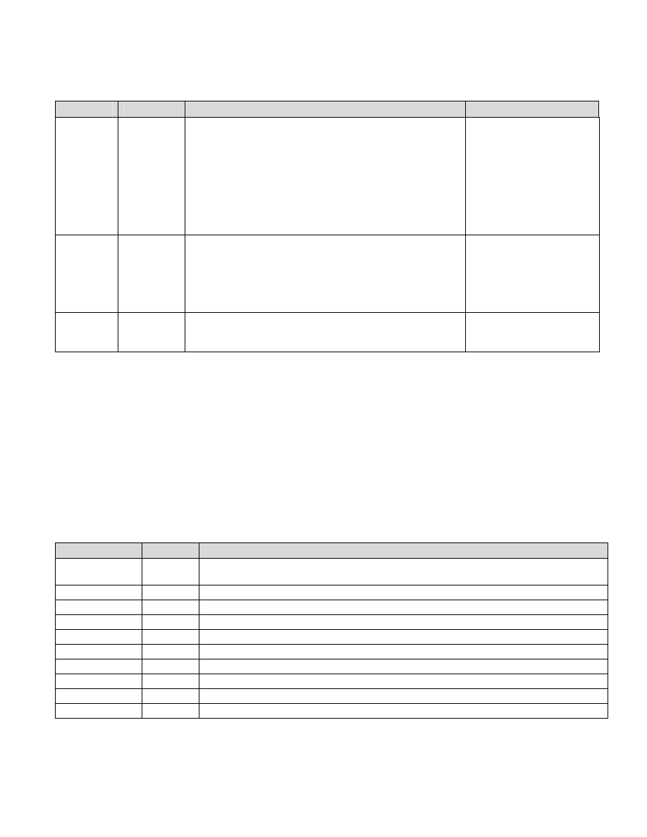
PostHASTE Post-Processor Formatting Reference Manual © 1989-2002 Paul Andrews & Ground Support
107
9.1.1.5
Variables used for subroutines or subprograms
You will find these variables in use in the SubStart, SubEnd and SubCall sequences.
Variable(s) Category
Details
Related / similar items
Sub
Subs
This is the value of the sub number, and can be used in the SubStart
and SubCall sequences.
Typical usages:
SubStart
O[Sub]
End
SubCall
M98 P[Sub] L[Times]
End
Times
SubLine
Subs
This is used in the SubCall sequence in place of [Sub] if the machine
must call a sub by its starting block (N) number (as opposed to using
the sub number itself).
SubCall
M98 P[SubLine]
End
Times
Subs
This is used to designate the number of times a sub repeats; it is
usually used only in the SubCall sequence.
See [Sub] details above for an
example of how this is used in
SubCall sequence.
9.1.1.6 Text
Variables
These are the only variables that do not output numeric data - instead they output text. You can instantly
tell the difference between a text variable and a numeric variable by the type of bracket that is used:
Numeric variables have [square brackets] and text variables have {curly brackets }.
See section 7.3 for details on...
- how to output text,
- outputting text variables and
- using text and text variables in the File Alias command.
Variable(s)
Category Details
{Partno}
Text
Use this variable to access or output the text in the PARTNO CL record. (Note: You can only use this
variable with CAM systems that output APT-CL files that include a PARTNO record.)
{CLPath} Text
The 'drive and path' to the CL file. Example: C:\CLFiles\
{CL Name}
Text
The CL file name only (no path or extension) Example: Job123
{CL Ext}
Text
The CL file extension (usually 3 letters) including the 'dot' Example: .INC
{TemplatePath} Text
The
'drive and path' to the format template file. Example: C:\PostHaste\Formats\
{Template Name}
Text
The format template file name only (no path or extension) Example: Fanuc 15iM, LeBlond
{Template Ext}
Text
The template file extension (usually 3 letters), includes the 'dot' Example: .pM3
{OutputPath} Text
The
'drive and path' to the final NC program file. Example: C:\NCPrograms\Mills\LeBlond\
{Output Name}
Text
The final NC program file name only (no path or extension) Example: Job123 Setup 1
{Output Ext}
Text
The final NC program file name extension (usually 3 letters), includes the 'dot' Example: .NCC
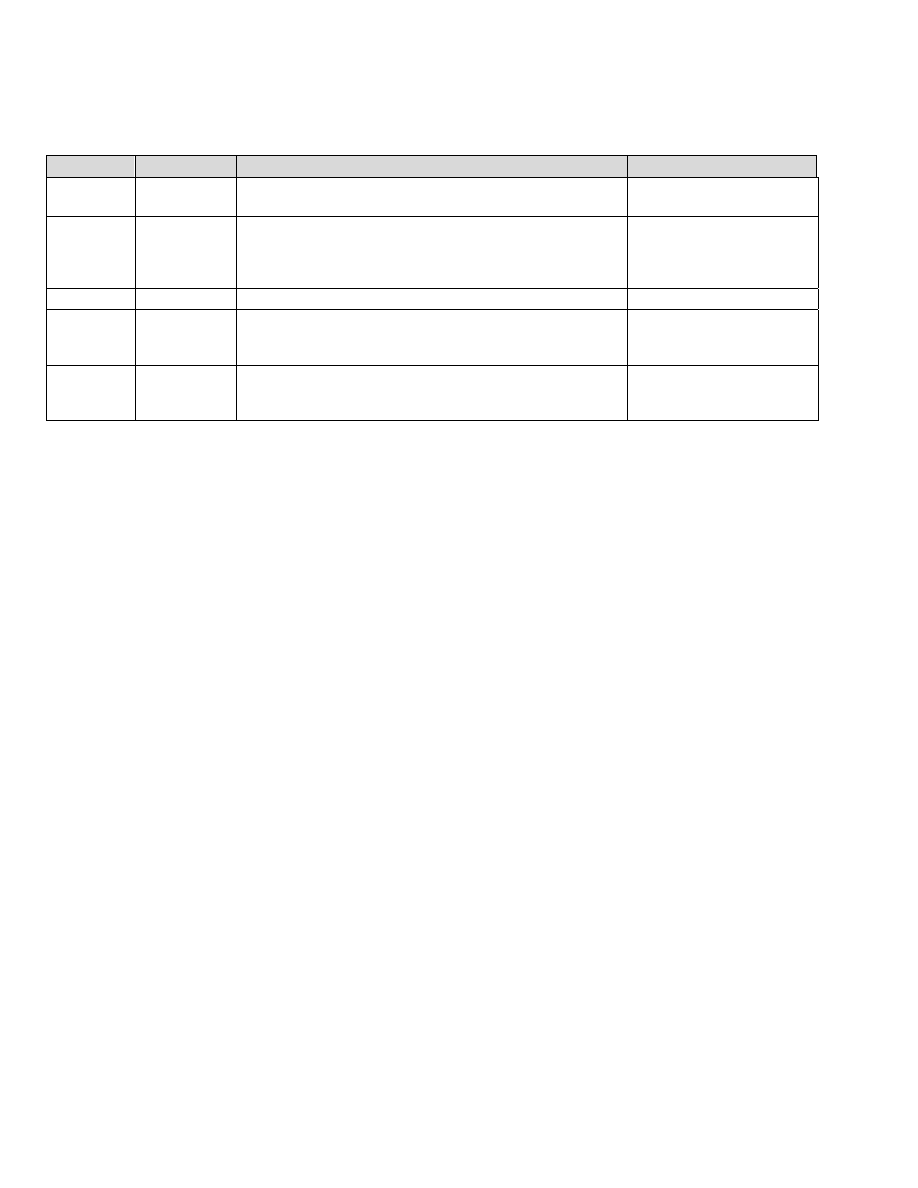
108
PostHASTE Post-Processor Reference Manual
© 1989-2002 Paul Andrews & Ground Support
9.1.1.7 Prompted
Variables
The values of these variables may not be set in the CL data. If you use any of these variables in your
format, then you will be prompted to enter their value(s) when the post starts processing your code.
Variable(s) Category
Details
Related / similar items
EndH, EndV
Prompted
Position to which you would like the tool to come to rest at END of
the program.
ToolH, ToolV, ToolD
MaxRPM
Tool change /
prompted (See
“Details”
column)
Maximum spindle speed limit (used with Lathe only; usually in
conjunction with a G50 or G92) The user will be prompted for the
first occurrence of this value if it is not found in the incoming CL
data.
Program#
Prompted
This number appears at the top of an NC program
ToolH,
ToolV, ToolD
Axis position /
Prompted
Tool change position. This is typically used in a ToolChange
sequence to move the tool to a particular (prompted) X, Y, and/or Z
location before executing the tool change (M6) proper.
EndH, EndV
WorkH,
WorkV,
WorkD
Prompted
Work origin offset coordinates (usually used with a G92 or G10
command).
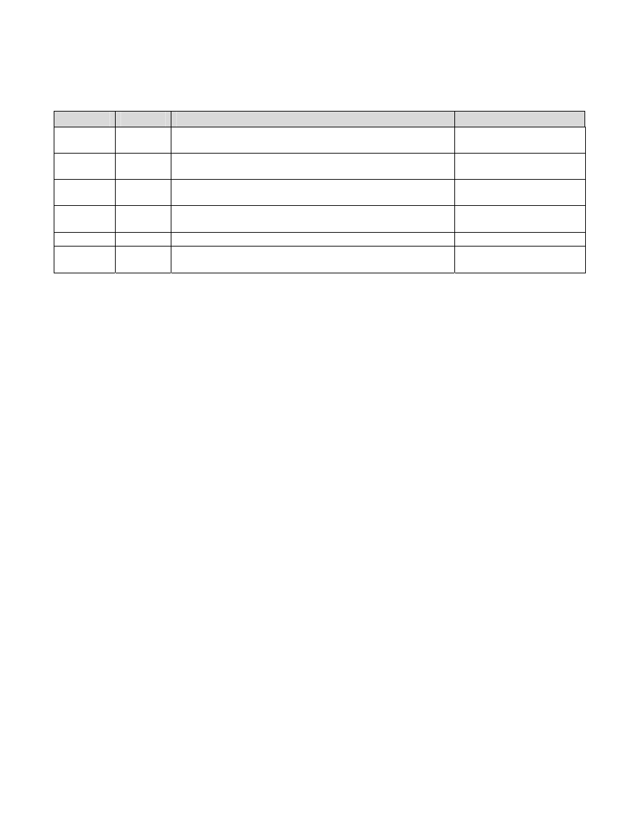
PostHASTE Post-Processor Formatting Reference Manual © 1989-2002 Paul Andrews & Ground Support
109
9.1.1.8
Variables used for Wire EDM posts.
These are variables that don't really fit into any other category...
Variable(s) Category Details
Related / similar items
InitPower
Wire EDM
‘Initial power’ setting value (Note – this variable will be set only if the CL
file supports this function.)
Power, SparkGap, WireFeed
LowerDist,
UpperDist
Wire EDM
Uppoer & lower wire guide distances.
Thickness
Power
Wire EDM
‘Power’ setting value (Note – this variable will be set only if the CL file
supports this function.)
InitPower, SparkGap, WireFeed
SparkGap
Wire EDM
‘Initial power’ value (Note – this variable will be set only if the CL file
supports this function.)
InitPower, Power, WireFeed
Thickness
Wire EDM
Thickness of the part.
LowerDist, UpperDist
WireFeed
Wire EDM
‘Initial power’ value (Note – this variable will be set only if the CL file
supports this function.)
InitPower, Power, SparkGap

110
PostHASTE Post-Processor Reference Manual
© 1989-2002 Paul Andrews & Ground Support
9.1.1.9
General Purpose (Misc.) variables
These are variables that don't really fit into any other category...
Variable(s) Category Details
Related / similar items
Block
General
The Block (or: sequence) number. This is automatically produced
according to the Sequence#s line in the format (see above). If the
'frequency' of the Sequence#s is set to 0 (like this)...
Sequence#s N 0 1 1 1 Char, freq., incr, start
...then N[Block] can be used to 'force' out N numbers on certain lines.
Example:
N[Block] T[Tool] M6
The exclamation point
(example: !0 ) can be used to
suppress the output of block
numbers.
EndN Lathe
Roughing
See discussion of StartN below.
StartN
FileSize
General
The number of bytes in the final NC program file (so far).
TotalCutDist
LinTol Rotary
axes
(NOTE – 5 axis and MillTurn posts only.) Set this variable to a non-zero
number to activate PostHaste’s “Linearization” function (that will insert
extra movements to break up movements with relatively large rotary
angle changes into shorter moves to reduce tool tip gouging.). This
variable is updated by the LINTOL record in APT CL files, or can be SET
by the user like this:
Set [LinTol] to .001
LINTOL (APT CL) record
Mode
General
This variable is used mostly in MillTurn machine formats to determine if
the operation is in milling or Turning mode.
For MillTurn posts this is typically set by the MODE or APPLY record
coming from the CL file …
[Mode] = 1 when Turning,... per these CL records:
MODE / TURN or APPLY / TURN
[Mode] = 3 when Milling. This occurs when these records are found:
MODE / MILL or APPLY / MILL
For Wire EDM posts…
[Mode] = 2 when in “2 axis” mode – typically when a contour is being
cut that requires no independent movement of the UV (auxilliary or
secondary) wire guide.
[Mode] = 10 when in “4 axis” (typically ‘XYUV”) mode
If you need to set the [Mode] yourself based on certain conditions, we
recommend that you follow these conventions:
Set [Mode] to 2 for “2D only” machining modes such as Laser,
flame, 2 axis EDM, etc.
Set [Mode] to 3 for simultaneous 3 axis milling mode.
Set [Mode] to 4 for simultaneous 4 axis milling mode.
Set [Mode] to 5 for simultaneous 5 axis milling mode.
Set [Mode] to 6 for ‘generic’ MillTurn mode { XZC }
Note: values of 7 to 9 are ‘reserved’ for possible future use – perhaps to
differentiate different MillTurn modes (XYZC, XZBC, XYZBC,)
MODE and TYPE commands
StartN, EndN Lathe
Roughing
These variables hold the “N numbers” (line numbers) of the starting and
ending of the ‘finish path’ that is used for lathe roughing cycles. They are
typically used in a Rough sequence like this:
Rough
G71 P[StartN] Q[EndN] U[VLeave] W[SLeave] …

PostHASTE Post-Processor Formatting Reference Manual © 1989-2002 Paul Andrews & Ground Support
111
Variable(s) Category Details
Related / similar items
end
Stop
General
If a ‘full stop’ is commanded in the CL file, [Stop] will equal 0.
If an ‘optional stop’ is commanded, this will equal 1.
Taper Lathe
Threading
(Lathe only.) [Taper] holds the ‘diameter difference’ between the start
diameter and the end diameter of the thread in AutoThread sequence.
The taper of a thread is usually associated with the letter I or R.
Example:
G76 X[V] Z[H] P[Depth] Q[Peck1] I[Taper] F[Frate]
Val1 to
Val20
General
These are general purpose 'user' variables that you can use for any
purpose you want. These variables are not set by anything in the
incoming CL data (unless you specifically use them in a Cycle or
UponRec sequence definition line).
When the post starts running, it always initializes these values to zero;
the values of these variables can be set or changed only by using ADD,
ASK, or SET statements or by putting them in the 'definition' (first) line of
a Cycle or UponRec sequence.
Warning:
Any time you add (what you think is) a 'new' variable to a post, make
sure that that variable is NOT being used for some other purpose in the
post already! Before adding a new variable, ALWAYS do a “Search” to
make sure that you don't mistakenly re-use a variable that is being used
for something else. Making this mistake can result in VERY strange
output - and a big mess to “debug”!
See the Rename command
(section 4.1.26) for more
information on defining your
own names for variables.
See the Add, Ask, Set, Cycle,
UponRec and IF (logic)
sections for examples of how
'user' variables may be used.

112
PostHASTE Post-Processor Reference Manual
© 1989-2002 Paul Andrews & Ground Support
10. Appendix B - List of “retired” functions.
When working with OLD post formats, use this list to find things that aren't discussed
earlier in the manual.
(Functions are listed in alphabetical order.)
As PostHASTE has advanced over many years, many of the original functions have been “retired” and
replaced by better methods. For sake of clarity (and to reduce confusion), we discuss only the newer
(better) solutions in the main sections of this manual.
HOWEVER, for purposes of “backwards compatibility”, the “old” functions still work. You may come
across some of these functions if you happen to be working on older PostHASTE templates. They are listed
here for your convenience - in case you ever run across them and need to know what they do.
Remember - there are better ways to achieve the same results: so we recommend that you do NOT use the
retired functions - use instead the functions listed in the “Better to use” column of the table below.
Item,
Retirement M/Y
Better to use:
Notes:
<angle brackets>
9/94
[Square brackets]
Square brackets are now used for variables because (1) they are easier to type
because they require no shift key, and (2) it makes IF commands less confusing if 'less
than' (<) or 'greater than' (>) symbols are being used.
2ndCircleCode,
4/93
ArcCode
Used for arc formats that require more than one line of code. (See p. 50)
CwCode, CcwCode
10/01
ArcCode
Used for arc formats that require more than one line of code. (See p. 50)
[CommentDelay]
variable
12/01
Comments command
See section 5.3.1for details on the Comments command.
CommentDelay was used in older formats to 'postpone' comments for a few lines so that
they would appear in a more useful location in your tool changes.
Varibles: [RPlane],
[VClear] and
[Vbite]
11/01
[Ilevel], [Rlevel] and
[Step], respectively
The names RPlane and VClear were misleading because RPlane specified the “Initial
Level” and has thus been changed to [ILevel]), and VClear specifies the “R level” (and
has thus been changed to [RLevel]).
Also, 'Step' sounds better than VBite.
DCompAdd,
LCompAdd
9/01
D[DComp]+20
H[LComp]+10 (etc.)
These commands were used with AuraCad/CAM product only. Since that product is no
longer available, we have removed these commands. It's easier to just 'hard-code' this
functionality as an equation (like D[DComp]+20) anyway.
PostForm.* files
8/01
“Single machine”
format template files.
(Examples: *.pM3
*.pM5 *.pT2 ...etc.)
One machine format per file now, please. (Too many advantages to list here.)
See Appendix B in the Getting Started manual for naming conventions. This is
important! (The post does certain internal processes differently depending on the
template file extension!)
PConfig.M file
8/01
PostHASTE.cfg file
Removed last vestiges of .M and .L file extensions.
[CoolantOff] variable,
2/01
Just use a simple...
M9
...instead of
M[CoolantOff]
A long time ago, one of our larger customers requested that we add this variable. Since
then, nobody has ever used it (as far as we know), and it makes thimgs more confusing,
so it has been retired.
If you really want to use it... (its value is set in the “Coolant” line) you may use it
anywhere in the sequences that you want to turn the coolant off like this:
M[CoolantOff] (See, M9 IS simpler, isn't it?)

PostHASTE Post-Processor Formatting Reference Manual © 1989-2002 Paul Andrews & Ground Support
113
11. Appendix C -
APT-CL Records recognized
PostHaste automatically recognizes the APT-CL records in following list that start with the following
words or symbols.
### NOTE -THIS SECTION IS "UNDER CONSTRUCTION" - WE WILL BE ADDING
DESCRIPTIONS AND DETAILS OVER THE COMING MONTHS. THANK YOU FOR YOUR
PATIENCE.
- 3/22/04 ###
In addition to knowing which CL records PostHaste recognizes, It is probably just as important to know
which CL records PostHaste IGNORES, so the first list below is a list of CL records that PostHaste
IGNORES
NOTE: If there is a record in your CL files that is NOT on either of these lists, PostHaste will issue a
warning.
HOWEVER - Remember you can always use an UPONREC sequence to...
- cause PostHaste to 'recognize' one of the commands on the "not recognized" list, or
- override PostHaste's 'default' way of handling a recognized record.
CL records IGNORED by PostHaste:
(listed in alphabetical order):
AUTOPS
END
FINI
GOHOME
HEADER
INTOL
MACHIN
MCS
ORIGIN
OUTTOL
POSMAP
PSIS
ROW
SELECT
SEQNO
TLON
TOOLNO
UNITS
NOTE: Even though PostHaste ignores these records, you can override that attribute and enable them with
an UponRec sequence in your template. Here's an example:
UponRec INTOL [Val1]
...
end

114
PostHASTE Post-Processor Reference Manual
© 1989-2002 Paul Andrews & Ground Support
CL records recognized by PostHaste:
CL Record Name
("Major word")
Description / notes / default actions, etc.
$$
Comment marker - the post will ignore all lines that start with '$$'. HOWEVER - you MAY 'Convert' them into actual
valid records that you may process with PostHaste. (See details on the Convert command.)
APPLY
Processed the same as MODE. (See MODE below.)
ARCDAT, ARCMOV
Some CAM systems use these records to describe arc movements instead of the standard 'CIRCLE & GOTO' pairs.
Note - the ARCMOV record must immediately follow the ARCDAT record.
CALSUB
(Along with ENDSUB and DEFSUB records,) describes subroutines or subprograms.
CIRCLE
Same as MOVARC
CLEARP
Sets the [iLevel] value.
COOLNT
Sets the [Cool] value.
CSYS
Some CAM systems output these records as a comment in the CL file. To utilize CSYS records, you must add the
following line to your template or PostHaste.CFG file:
Convert '$$-> CSYS' to 'CSYS'
If this is done, then PostHaste’s ‘default’ handling of these records is to use them to automatically calculate the
rotary angle(s). PostHaste also sets the variables [CSys1] to [CSys12] to the values that are in the CSYS records.
Note - You can affect the way PostHaste interprets this record by use of the InvertCSYS? switch
CUTCOM or CUTDIR
Indicates [Side] - typically used in the Infeed sequence.
CUTTER
At this time, only the [ToolDiam] and [ToolRad] variables are set by PostHaste (from the number immediately
following CUTTER .
CYCLE
Specifies all types of holemaking cycles, and lathe threading.
DEFSUB
(Along with ENDSUB and CALSUB records,) describes subroutines or subprograms.
DISPLY
Same as PPRINT (see notes re PPRINT below)
ENDSUB
(Along with DEFSUB and CALSUB records,) describes subroutines or subprograms.
FEDRAT
Spindle speed and mode
FROM
GOTO
General XYZ position of the endpoint of a linear or circular move, or the position at the 'top' of a hole. (Also see
MULTAXI below.)
HOMEPT
INDEX
Identical to the ROTATE command - see the note re ROTATE below.
INDIRV
Used for arcs in CATIA...
INSERT
Text in the INSERT record will be placed directly and immediately into the final NC program. (No comment markers
will be added.)
LINTOL
Linearization tolerance - used in 5 axis milling applications. (This sets PostHaste’s [LinTol] variable.)
LOAD
PostHaste interprets LOADTL, LOAD and TURRET identically.
LOADTL
PostHaste interprets LOADTL, LOAD and TURRET identically.
MODE
Processed the same as APPLY
MOVARC
Same as CIRCLE
MSYS
Similar to CSYS - but this is automatically interpreted as an 'inverted' CSYS. (Note - Unigraphics outputs MSYS
records instead of CSYS, and Unigraphics does not put them in a ‘comment’, so no Convert command is needed for
the post to read these records from Unigraphics CL files.)
MULTAX
/ ON or / OFF - indicates that upcoming GOTO records will include or exclude IJK (Tool shaft) vector data
PARTNO
The text following PARTNO will be put into the {PartNo} text variable. (NO NUMERIC data will be parsed from the
incoming PARTNO text.)
PPRINT
Text following PPRINT will be output in the NC program as a comment. (PostHaste processes PPRINT records the
same as DISPLY records.) You can use the comments command within your template to indicate where you want
the comments to appear in the NC program.
RAPID
Turns the next GOTO into a rapid (typically G0) move.
RETRCT
ROTATE, ROTABL or
ROTHED
Used to set the rotary axis variables - typically [RotAngle] (if only 1 rotary axis on your machine) or 2 of the
following: [AAxis], [BAxis], [CAxis]. (PostHaste processes the INDEX command in the same way.)

PostHASTE Post-Processor Formatting Reference Manual © 1989-2002 Paul Andrews & Ground Support
115
SET
Used to set the [Work] (Work fixture offset) variable.
SPINDL
Spindle speed and mode
STOP
Triggers PostHaste's STOP sequence. (typically M0 or M1, depending on template formatting)
SYNCTR
Used in synchronizing multiple turrets (on lathes & MillTurn machines) or multiple wire guides in 4 axis wire EDMs.
THREAD Thread
turning
TLAXIS
Similar to CSYS - can be used to calculate rotary angles.
TURRET
PostHaste interprets LOADTL, LOAD and TURRET records identically.

116
PostHASTE Post-Processor Reference Manual
© 1989-2002 Paul Andrews & Ground Support
12. Appendix D -
Handling Rotary Axes
This section of the manual lists information that you will need to understand in order to handle rotary axis
issues with PostHaste.
NOTE - This section of the manual is 'under construction' - please excuse the temporary 'men at work' signs
such as '###' or '<<<'. Thank you.
Definitions:
Indexing vs.Rotary Milling:
• Indexing refers to a rapid move with rotary motion. (Rotary 'positioning' only.)
• Rotary Milling refers to simultaneous rotation while actually cutting (that is, the rotary axis [or
axes] are moving at the same time that the XYZ axes are moving at the cutting feed rate).
12.1 [RotAngle] vs. [AAxis], [BAxis] and [CAxis]
Generally speaking, templates for machines that have only one rotary axis (for example, 4 axis mills) use
the [RotAngle] variable. Machines with more than one rotary axis do not use the [RotAngle] variable;
instead, they use a combination of 2 or more of the following variables: [AAxis], [BAxis] and/or [CAxis]
The only exception to the above is that some machines with only a single rotary axis (most notably punch
presses with a rotating tool holder) can use the [AAxis], [BAxis] and [CAxis] variables, but only when the
CAM system outputs corresponding ROTATE or ROTABL records into the CL file that contain the
AAXIS, BAXIS or CAXIS parameters (see the discussion below).
12.2 Where do the actual rotary angle values come
from?
The actual rotary angle(s) (that are output by the [RotAngle], [AAxis], [BAxis] and [CAxis] variables) are
calculated from one of the following types of CL data ( - these are listed in the order of 'most desirable'
to ' least desirable'):
12.2.1 MULTAX data
### This usually the most desirable data to use for calculating rotary angles. This data can be used for both
indexing and rotary milling. The CL file will include a MULTAX / ON record, then the GOTO records will
include 6 parameters (XYZ coordinates and an IJK vector); the IJK vector indicates the direction that the
tool shaft is pointing (away from the tip).

PostHASTE Post-Processor Formatting Reference Manual © 1989-2002 Paul Andrews & Ground Support
117
Examples:
Typical (3 axis) GOTO records (no MULTAX data):
…
GOTO / 4.6574936, -1.4959458, -0.4900000
GOTO / 4.6154199, -1.4861985, -0.4900000
RAPID
GOTO / 4.6154199, -1.4861985, 0.1000000
…
MULTAX / ON record, followed by GOTO records with MULTAX (IJK vector) data:
…
MULTAX / ON
<< Initiates 5 axis positionining (XYZ and IJK)…
RAPID
GOTO / 4.85985, -1.33816, 1.00000, -0.0879675, -0.0000970, 0.9961233
FEDRAT / PERMIN, 200.000000
GOTO / 4.85985, -1.33816, 1.18560, -0.0879675, -0.0000970, 0.9961233
…
MULTAX / OFF
<< Back to 3 axis (XYZ only)…
GOTO / 4.6574936, -1.4959458, -0.4900000
GOTO / 4.6154199, -1.4861985, -0.4900000
RAPID
GOTO / 4.6154199, -1.4861985, 0.1000000
…
12.2.2 Coordinate system (CS or CSYS) data
Unless special arrangements are made in the template, CSYS data can only be used for indexing or multiple
setups on a 3 axis mill – and usually cannot be used for rotary (simultaneous 4 axis) milling
Since the ‘preferred method’ of rotary axis controls is through the use of MULTAX data (see above),
CSYS data is NOT usually accessible to the post unless you specifically activate it by using a Convert
command like this:
Convert '$$-> CSYS' to 'CSYS'
Ignore MULTAX
This line must be added to prevent redundant rotary data!
Important!!! Please note that if you are using CSYS data (by including the Convert line above, you must
disable the MULTAX data by including the Ignore MULTAX command in your template as well!
### ###>>> “Under construction…” – Need to discuss 'in plane rotation' and 'local coordinates'
limitations/capabilities. <<<###
12.2.3 TLAXIS record data
This is usually found in CATIA CL files, and is somewhat of a hybrid of both of the MULTAX and CSYS
methods described above. It is similar to MULTAX data because it indicates a single IJK (tool shank) unit
vector that indicates the XYZ direction from the tool tip back along the center line of the tool (towards the
center of the spindle face). However, it is similar to the CSYS method because TLAXIS records appear

118
PostHASTE Post-Processor Reference Manual
© 1989-2002 Paul Andrews & Ground Support
occasionally in the CL file for purposes of indexing (that is, rapid rotary positioning) rather than
simultaneous rotary machining - which requires an IJK (MULTAX) vector in every GOTO record.
Examples:
TLAXIS/ 0.000000, 0.000000, 1.000000
(Tool shank pointing towards Z+ axis [Typ. A0 and/or B0])
...or...
TLAXIS/ -1.000000, 0.000000, 0.000000
(Tool shank towards X- axis [Typ. B-90])
TLAxisEnabled? switch
TLAXIS records are ignored by PostHaste - unless you use the TLAxisEnabled? switch and set it to Y like
this:
TLAxisEnabled? Y
12.2.4 ROTATE, ROTHED or ROTABL records
Using these records is the least desirable of the methods of obtaining rotary angle information. It is
undesirable because the CAM system has actually calculated the rotary values, rather than letting the post
calculate them from the 'vector' (IJK) information that is used in any of the above methods (MULTAX,
CSYS or TLAXIS). The problem with that is that most CAM systems do not have the kinematic
information regarding the rotary axes on your machine, so many times the CAM system outputs bad
angles.
With that said, sometimes this is the only information available, so alas, we must sometimes use it.
Fortunately, IF your CAM system sets these values properly, then you should have no problem.
Special attention must be paid to the way these records are handled. If any of these records include the
parameters AAXIS, BAXIS or CAXIS, then the post will correspondingly set the [AAxis], [BAxis] or
[BAxis] variables, respectively - EVEN IF THE ANGLES BEING SET DO NOT MATCH THE ACTUAL
KINEMATICS OF YOUR PARTICULAR MACHINE. This can become very troublesome and
complicated, so again, try to avoid using the ROTATE, ROTHED and ROTABL records if at all possible.
### <example> ###
The VertCSame? switch
###>>> Move this topic into the 5ax addendum. <<<###

PostHASTE Post-Processor Formatting Reference Manual © 1989-2002 Paul Andrews & Ground Support
119
13. Appendix E -
What's new with PostHASTE
and this manual?
RIGHT HERE is where you can find out about the latest features of PostHaste - without
having to look through the entire manual!
The chart below tells you where to find out about important and/or recent changes to PostHaste and this
manual. (There are probably lots of very useful things you didn't know about PostHaste - take a minute to
skim the leftmost column of the chart below. You'll learn a lot!)
Notes:
• For the most part, the chart is listed in order of 'newest to oldest', so whenever you get a new version of
PostHaste (this manual), start reading from the top of the list to learn about the new items. (To make
sure you see all of the new items, don't stop until you reach 'familiar territory'.)
• We have listed the items that we feel are the most important for you to know about in boldface type.
Don't miss these!
Note: in the Doc or Feat.? Column...
• D means that it's a documentation change (correction, addition, explanation, examples, etc),
F means that it's a new feature of PostHaste.
• (new) means that (even if it's not a new feature) it is a completely new subject in this manual, so you
might not have heard about it before. Check it out!
New Item:
Doc or
Feat.? -
mo./yr.
Notes:
Read about it
in section...
How Rotary Axes
are output (and
controlled by CL
data. )
D – 2/05 Important discussion for anyone processing 4 or 5 axis milling (or MillTurn)
programs; the significance of the [Rotangle] and [AAxis], [BAxis] and [CAxis]
variables and the following CL records: MULTAX, CSYS (Coordinate system or CS)
TLAXIS, ROTATE, ROTHED, ROTABL.
Appendix D -
Handling Rotary
Axes
Expanded
discussion on
defining the (4
axis) INDEX
sequence
D – 1/05 Sometimes (when programming a horizontal 4 axis machine) you may have a CAD
model that is drawn so that the part must rotate about the Z axis, but your machine
rotary table actually rotates the part about the Y axis. This discussion explains how
you can define your INDEX sequence to handle that.
Subsection of
5.2.4.3
Handling ‘Optional
Stop’ (OPSTOP)
CL records
D – 1/05 Discussion / example of using the UponRec sequence to output code required for
an ‘optional stop’ (CL OPSTOP record).
5.2.4.4
Updated Appendix
A (Variable list)
with many entries.
D – 1/05 Added discussion of these variables (most of which have been available for a
long time, but had not yet been documented):
ADir (BDir, Cdir), ADist (BDist, CDist), ArcDir, ArcPlane, CPref, FileSize, H2 (V2),
HCtr2 (VCtr2), InitPower, LowerDist (UpperDist), Normal1 (Normal2, Normal3),
PointH (PointV, PointD), PolarAngle, PolarDist, Power, SparkGap, StartN (EndN),
Stop, Taper, Thickness, WireFeed.
Added/improved information on these variables:
Appendix A -
List of Variables

120
PostHASTE Post-Processor Reference Manual
© 1989-2002 Paul Andrews & Ground Support
New Item:
Doc or
Feat.? -
mo./yr.
Notes:
Read about it
in section...
Mode,
The AutoThread section (Section 5.2.4.2) also now includes the variables: Starts,
TipAng
AutoThread
sequence, related
variables
D - 4/04 Of special interest to lathe users; Automatic lathe threading cycle (typically G76)
documented - along with use of the [TParams], [Passes], [Chams], and [TipAng]
variables.
5.2.4.2
[Cycle] [Style] and
[Spindle#]
variables
both -
04/04
Also of special interest to lathe users; additional values for [Cycle] and [Style]
are now available, and we have added documentation of the [Spindle#] variable.
(Note: The [Spindle#] variable has been available since 1//2000, but somehow it
escaped being documented! Sorry! :-o )
9.1.1.4
[Turret] variable,
RevTurret2?
switch
D - 4/04 ...and even more for lathe users; PostHaste has some special features for Multi-
turret lathes. See these sections for into on the [Turret] variable and RevTurret2?
switch, respectively.
9.1.1.4
4.1.30
Verbose? switch
F - 3/04 Setting this to Y makes the post output some additional comments that may be
helpful in 'debugging' your templates.
4.1.41
[PolarBreak]
variable
F - 7/'03 'Polar interpolation' control: For MillTurn posts, setting the [PolarBreak] value lets
you control how & when lines and arcs milled on the face of a part are
converted/broken into a series of short 'polar' (typically X,C) moves.
9.1.1.1
Appendix added:
"APT-CL records
recognized"
D - 3/'04 Now there is a list of the APT-CL records that the APT version of PostHaste
recognizes automatically.
Appendix C
Topic "Work
Fixture Offsets" -
moved.
D - 3/'04 This was previously "Appendix C". We felt that it deserved a chapter in the manual,
so we added section 6. (Note - The contents of that section have not changed - we
just moved it.)
6
TLAxisEnabled?
switch
F - 2/04 Allows use of the TLAXIS record (for machines with rotary axes) to calculate rotary
axis angles.
Appendix D -
Handling Rotary
Axes (Section
12.2)
RELATE option on
"Upon... Unique"
sequences.
F - 2/04 Allows you to relate any variable to a unique condition. For example: Relate a 'work
offset' variable to each face of your workpiece so that the post will output the
correct work offset number that has been calculated and related to each face (A or
B angle) of the workpiece
0 (see the
'...Relate...'
subsection)
SpliceSubs? switch F - 10/03 Lets you prevent subs from being including in the main output file.
7.6.3.4
Rename
command
F - 10/03 User-defined variable names! The Rename command lets you to make up any
name you want - for any variable.
4.1.26
WindowSize
configuration
setting
F - 9/03 If your post window is too small (if any of the buttons are missing or only partially
visible) then you can configure the width and height (in pixels) of the main
PostHaste window.
Appendix A of
'Getting Started'
manual
ArcPlane
command and
[ArcPlane] variable
D - 6/03 The ArcPlane command (and optionally the [ArcPlane] variable) can be used in mill
format templates to support arc output in the ZX (typically G18) and YZ (typically
G19) planes.
4.2.1
[LastH], [LastV]
and [LastD]
variables.
D - 6/03 A very important discussion of these variables has been added - read about these
in section 9.1.1.1 (That is inside Appendix A - look in the left column of that table to
find the entry entitled “LastH, LastV, LastD, LastRotAng”.)
9.1.1.1
Helical arcs
D - 6/03 Everything you ever wanted to know about handling helical arcs - including
examples of some special cases.
4.2.7.1
LOOP structures
###
Create 'loops' for controlled repetitive processing of... anything!
(You can even created 'nested loops'.)
Coming soon!
Equations !
D (new!)
- 4/'03
You can now follow letters with equations such as
X[H]/2 or Ycos([RotAngle])*[Val12]
(You can also use equations in other areas, too.)
7.1
Outputting text
directly,
F -
(new!)
PostHaste now features 'text output' capability. In addition to any 'hard-
coded' text that can be output from within any sequences, text variables
'Text' topic: 7.3
List of text

PostHASTE Post-Processor Formatting Reference Manual © 1989-2002 Paul Andrews & Ground Support
121
New Item:
Doc or
Feat.? -
mo./yr.
Notes:
Read about it
in section...
{Text} variables,
and other text-
related functions
4/'03
(such as {CLName}) can be used for many purposes including commenting
and creation of specific files in specific folders.
variables:
9.1.1.6 File
Alias: 5.3.4
Call (command)
F -
(new!)
4/'03
Use Call to 'reuse' (output) any sequence from inside any other.
e.g. You can usually use this to eliminate lines in your ToolChange sequence that
are 'duplicates' of lines in your 1stToolChange sequence.
5.2.5
CallMe
F -
(new!)
4/'03
Use CallMe to create your own sequences! (Then use Call to output them.)
This can greatly reduce the complexity and the number of lines needed in
your template!
5.2.5
[PeckClear]
D - 4/03 'Rapid into peck' drill tip clearance
4.1.2
AND and OR
usage with IF
D (new) -
2/03
AND and OR can now be used in IF structures to test for 2 conditions at a time.
7.5
Indenting lines in
an IF structure
D (new) -
2/03
For more visual clarity within the template, you may indent lines within an IF
structure with a single space.
7.5
Automatic
Multiple-part
output
D (new)
- 2/03
You can easily set up your posts to automatically generate multiple-part
programs (using subroutines and work offsets [G54, G55, etc.]) - even if you've
only programmed a single part in your CAM system.
If you EVER need to do multiple-part setups , then READ THIS!
7.6
PostHaste.LOG
D (new) -
2/03
Did you know that PostHaste creates a log file that is very helpful in 'debugging'?
7.7
LocalOutput?
switch
D (new) -
3/03
For machines with rotary axes, use this switch to output your XYZ data relative to
the 'local' [Work] (G54, G55, etc.) origin for each face of your part. (Restrictions
apply!)
4.1.22
[TotalCutTime],
[TotalCutDist]
F - 12/02 New variables that track your total feed time and distance so far.
9.1.1.1
[MoveTime]
(doc. Error)
D - 12/02 Before this date, the explanation of [MoveTime] mistakenly said that it was
measured in seconds. It is actually measured in minutes.
9.1.1.1
MOD letter format
modifier
D - 10/02 The MOD (modulo) letter format modifier makes rotary axis output possible on
machines that have a 'numerical' limit of 360 (and/or -360) on the rotary axis.
3.1.2
Coolant command,
the [Cool] variable.
D - 10/02 This section of the manual was updated to clarify the use of these commands and
variables.
4.1.6
Appendix C - Work
offset details
D -
10/'02
This manual now includes an exhaustive discussion of how PostHaste handles
Work/Fixture offsets (a.k.a. 'WFO's” and/or G54) - including details on the [Work]
variable and the Work and WorkDefault commands. .
Appendix C
The NoComment
and All options
(for Replace)
F – 8/'02 NoComment prevents 'Replaces' from being performed on your comments,
All 'Repeats' a replacement until all occurrences have been replaced.
7.4
Unique modifier to
the UPON record
F - 8/'02 Trigger output or processes only upon finding a unique ('not previously used') value
of any variable... Can be used (for example) in a tool list to prevent duplication of
tools that are used twice, or t o create unique G10 lines whenever a 'new' index
(rotary position) is encountered.
0
No-Opt letter
format modifier
D - 8/'02 Inhibits PostHaste's 'zero optimization'; this lets you output zeroes as “0.” instead of
“0”
3.1.2
Index sequence
D - 8/'02 Format the output for Rapid moves that include rotary motion.
Error!
Reference
source not
found.
Set command
D - 8/'02 Set the value of any variable to any number, variable or equation
5.3.5
Arc-related
variables
D - 8/'02 To get familiar with any of these variables...
ArcRad, ArcStartH, ArcStartV, HCtr, VCtr, Ival, Jval, StartAng, EndAng, Sweep
4.2
'Spindle Range'
codes (tactic)
D - 8/'02 This is an example of a good 'general purpose' tactic that has many other uses –
you should know how to do this!
5.3.6 (example
of Set usage.)

122
PostHASTE Post-Processor Reference Manual
© 1989-2002 Paul Andrews & Ground Support
New Item:
Doc or
Feat.? -
mo./yr.
Notes:
Read about it
in section...
[UnitMode]
D - 8/'02 Value output corresponds to the values listed with the INCH/MM command. 9.1.1.4
Tolerance
command
D - 8/'02 Set the post's rounding tolerance (to prevent rounding errors from accumulating
while outputting incremental values).
4.1.37
Spaces? switch
D - 8/'02 Puts spaces between words. If you didn't know about this, then read this section:
4.1.32
Each, EOB and
EOF commands.
D - 8/'02 These let you specify a 'word' to be output on each line of your program as well as
the 'end of block' and 'end of file' character sequences, respectively.
4.1.9 to 4.1.11
File
commands
F – 7/02 Many file handling functions are now available that allow you to ...
- do 'multi-pass processing'
- create/edit multiple output files
- create tool lists at the top of your program files... and more!
5.3.4
NoEol (and EOL)
commands
F - 2/01 NoEOL lets you join several sequence lines into a single line of output (by
suppressing the 'end of line' that PostHaste outputs after every sequence line).
5.3.5
Comments
command
F –
12/01
Gives you complete control over the exact location of your comments in the final
NC code!
5.3.1
Template file
extension naming
conventions
F – 1/'02 The file extension tells PostHaste what type of machine is being formatted. What's
the difference between a .pT2 and a .pU5 template file? Find out here.
1.2
Notes: /
EndOfNotes (or
EndNotes)
F - 11/01 Use Notes: and EndOfNotes (or EndNotes) lines to include large blocks of
comments (without having to 'indent' them), or to 'comment out' a portion of your
template.
4.1.25
DivBy and DivInto
letter format
modifiers
F – 7/'01 Letters can be formatted for 2 different types of Division operations.
3.1.2
Document Outline
- PostHASTE Postprocessor Formatting Reference Manual
- Table Of Contents
- PostHASTE Basics
- Format templates - the basics
- The Letter Formats
- Commands and 'Switches'
- The “Sequences”
- Work Fixture Offsets (G54, etc.):how they [Work]
- Special features
- “Special Case” Tactics & Notes
- Appendix A - List of Variables
- Appendix B - List of “retired” functions
- Appendix C -APT-CL Records recognized
- Appendix D -Handling Rotary Axes
- Appendix E -What's new with PostHASTEand this manual?
Wyszukiwarka
Podobne podstrony:
PostHASTE for GibbsCAM 2005 Format Reference Manual
PostHASTE Formatting Reference Manual
[ebook] Assembler Intel Architecture Optimization Reference Manual [pdf]
Bash Reference Manual [EN]
( SPC ) STASTICAL PROCESS CONTROL REFERENCE MANUAL
For Dummies Visual Studio NET C++ for Dummies Quick Reference Guide
Evidence for the formation of anhydrous zinc acetate and acetic
The GNU C Reference Manual
PS4 Suscosoft S40 Function Block Reference Manual h1365g
Need for Speed Porsche Unleashed Manual Win EN
Spectral intensity measurement for soot formation of benzene behind reflected shock waves
Need for Speed High Stakes Manual Win EN
truck adblue emulator for mercedez benz user manual
operator reference manual kongsberg maritime sdp
alesis dm5 instrukcja reference manual 163339
więcej podobnych podstron