V1.0
Local Service Organization Service Manual
C
C
C
3
3
3
5
5
5
S
S
S
e
e
e
r
r
r
i
i
i
e
e
e
s
s
s
6 , ( 0 ( 1 6 & 2 0 0 8 1 , & $ 7 , 2 1 6 8 1 / , 0 , 7 ( '

V1.0
i
Table of Content
C H A P T E R 1
Cellular Communication
Coverage Concept
1
GSM Network Architecture
2
Subscriber Identity Module
3
SIM Application Toolkit
4
Extended GSM 900 - EGSM
5
Built-in Modem
5
Data Application
6
C H A P T E R 2
Level 2 Service Guide
Introduction
7
C35 Series Technical Information
8
Accessories
10
General Information
11
C35 Series Exploded Diagram
13
Mechanical Concept
14
Hardware Concept – Block diagram
15
Hardware Description
16
Power Supply Concept
18
Over voltage Condition
18
Battery 19
Short Circuit Protection
19
Charging
19
Deep Discharge Battery
20
C35 Spare Parts Level 2
21
Disassemble the C35
22
Disassemble/Assemble Lower Housing
24
Disassemble/Assemble Control Board Assy 25
Disassemble/Assemble Upper Housing
27
Assemble the C35
28
Mobile Software Programming
30
Language Groups
32
Customer Specific Initialization
34
International Mobile Equipment Identity
34
Phone Unblocking
35
C H A P T E R 3
Siemens Service Equipment
Introduction
37
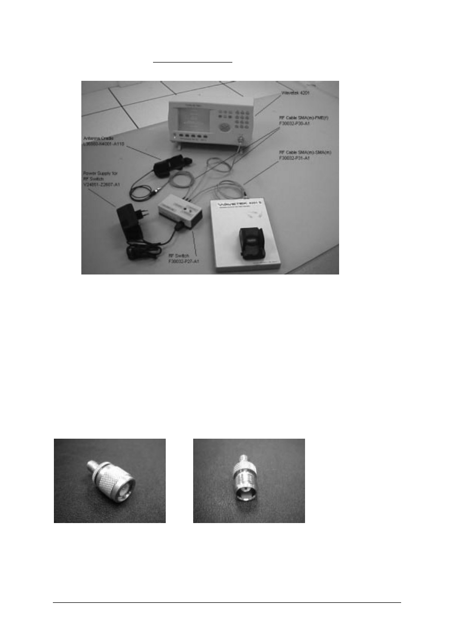
Other equipment
39
Software Installation
40
Configuring the test software
41
Running the test sequence
42
ANNEX A
46
ANNEX B
49
C H A P T E R 4
Level 2.5 Repair Document
Introduction
50
Antenna Connector
51
Ringer
55
Bottom Connector (Lumberg)
58
Display Connector
62
Keyboard LED
66
Display LED
69
Infrared Diodes
73
ANNEX C
PC Adapter Cable & Accessories C35
76
Power Plug for C35
77
Car installation Ratio Unit, C35
78
Car Installation kit Handfree kit
79
Car Installation kit Handfree Pro.
80
Car Installation Comfort GPS, C35
81
References
83
V1.0
1
Cellular Communication
Coverage Concept
.
he cellular systems is made up of numerous transmitting and
receiving sites, whose individual coverage areas partially overlap. The
concept of frequency re-use, same frequency is used by several sites,
allows a high traffic density in a wide area. Due to the limited
transmission range of the terminals, cellular systems are based on a large
number of base stations on the infrastructure side, scattered over the area to
cover, with each covering a fairly small geographical zone called cell. Cells are
often represented by hexagons (see figure 1.1.).
FIGURE 1.1
CELLULAR COVERAGE REPRESENTATION.
Chapter
1
T
V1.0
2
GSM Network Architecture.
GSM network can be broadly divided into three broad parts, namely:
1. Mobile Station(MS) carried by the subscriber,
2. Base Station Sub-system(BSS) which controls the radio link with the mobile station.
3. Mobile Switching Center(MSC) which performs the switching of calls between the mobile
users, and between mobile and fixed network users.
FIGURE 1.2 GSM ARCHITECTURE
Each mobile station is given a unique identity. As soon as the mobile phone is turned on, it
registers with the network and is authenticated, as such the network could always find the
mobile phone.
Larger amount of data is being exchanged to and from the following functional blocks in the
MSC:
Visitor Location Register, VLR
Stores information about mobile subscribers that enter it coverage area which is associated with
the geographical area where the mobile is currently roaming. When there is an incoming call for
the mobile, the HLR is interrogated about the present address of the VLR.
Home Location Register, HLR
A database that contains all data concerning the subscription of the mobile subscriber, i.e. their
access capabilities, subscribed services, and supplementary services. It also contains
information about the VLR that is handling the mobile station currently. When the mobile
changes location, the HLR is updated accordingly. It also provides the MSC with information
about the MSC area where the mobile is actually located to allow incoming calls to be routed
immediately to the called party.
V1.0
3
Authentication Center, AUC
Stored information that is necessary to protect communication through the air interface against
any intrusions. The legitimacy of the subscriber is established through authentication and
ciphering, which protects the user information against unwanted disclosure.
Equipment Identity Register, EIR
An option the network operator can use to enforce security. With this feature the network can
identify defective or stolen mobile that may not be used in the network.
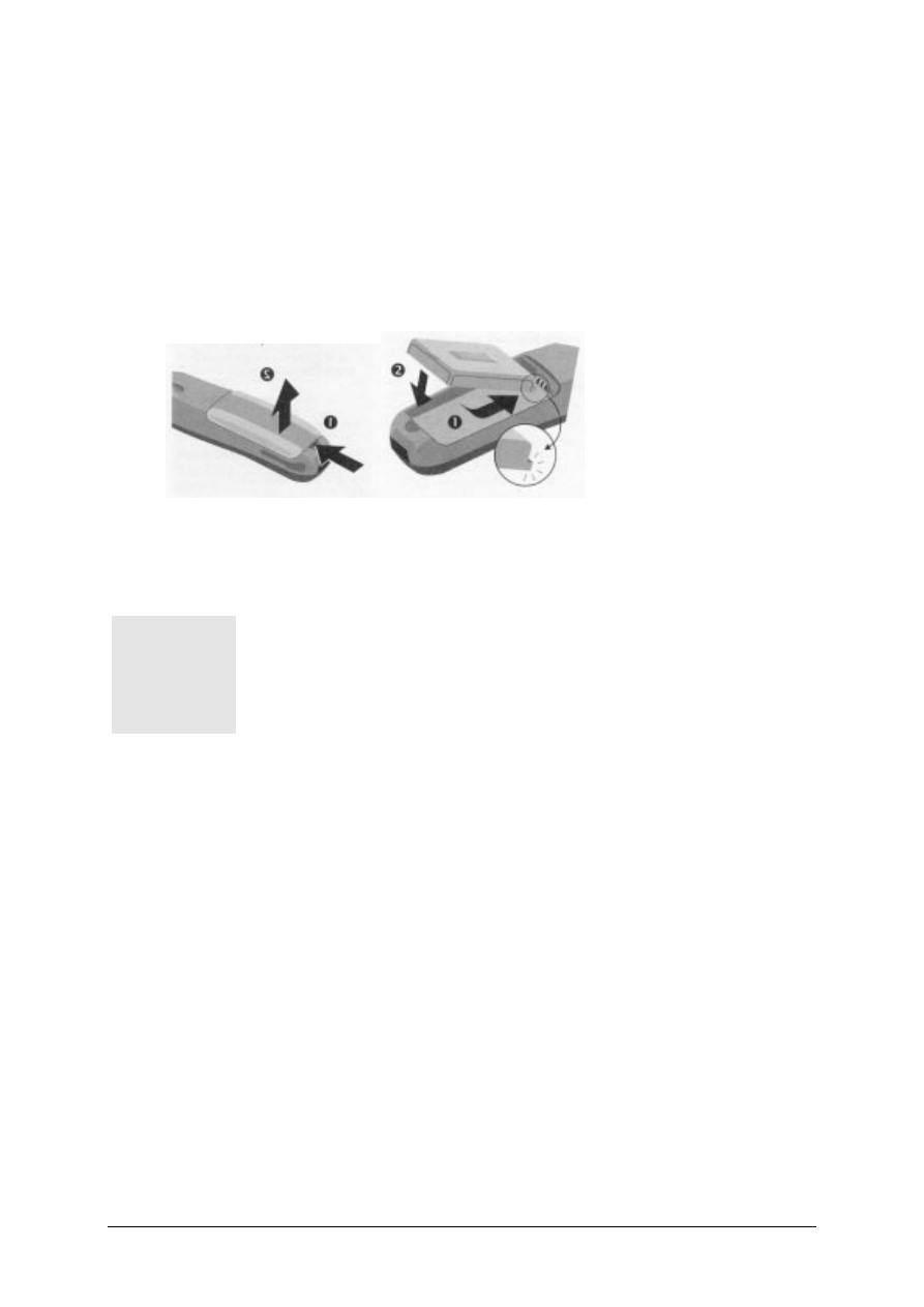
Subscriber Identity Module(SIM)
SIM is a smart card which has a computer and memory chip that is permanently installed in the
mobile equipment. It comes in either the size of a credit card or smaller version known as the
plug-in SIM.
The subscriber information, which includes a unique number called the International Mobile
Subscriber Identity (IMSI) is stored in the SIM card. SIM card identifies the subscriber to the
network.
FIGURE 1.3 INSERT SIM CARD
Figure 1.3 illustrates the steps for inserting the SIM card into the C35 series.
1
V1.0
4
To protect the SIM card from improper use, a security feature, a four digits personal identification
number (PIN), is built in. The PIN is stored in the card and can be changed by the subscriber.
PIN2 is required for additional funtions available with a special SIM card (Consult the operator for
more information about the PIN.
A code (PUK) is provided for unlocking the SIM card if the SIM card is blocked
Change PIN Procedures.
CHART 1.1 PIN CONTROL
SIM Application Toolkit
SIM Applications Toolkit (SAT) allows the flexibility to update the SIM, to change the services
and download new services over the air. In the SAT specification, the short message service is a
Β
MENU
SETUP
SECURITY
CODES
CHANGE PIN
CHANGE PIN2
{ENTER PIN NUMBER}
CHANGE
{ENTER NEW PIN} AND PRESS OK KEY.
{ENTER NEW PIN) AND PRESS OK KEY.
V1.0
5
key mechanism for personalizing the SIM in each user’s GSM phone. It is designed as a client-
server application. C35 series supports SAT Class 3 specification.
When active, the name of the service may appear in the menu, and there will be sub-menu if
more than one application is active. Figure 1.6 is the SAT icon.
FIGURE 1.4 SAT ICON
Extended GSM 900, E-GSM
This is a new standard that allows Network Operators to increase their capacity through an
extended frequency. The frequency range of E-GSM is as follows:
•
Mobile Transmit: 880 – 915 MHz
•
Mobile Receive: 925 – 960 MHz
C35 series is a GSM Phase 2 / Phase 2+ Dualband E-GSM / GSM 1800 mobile phone.
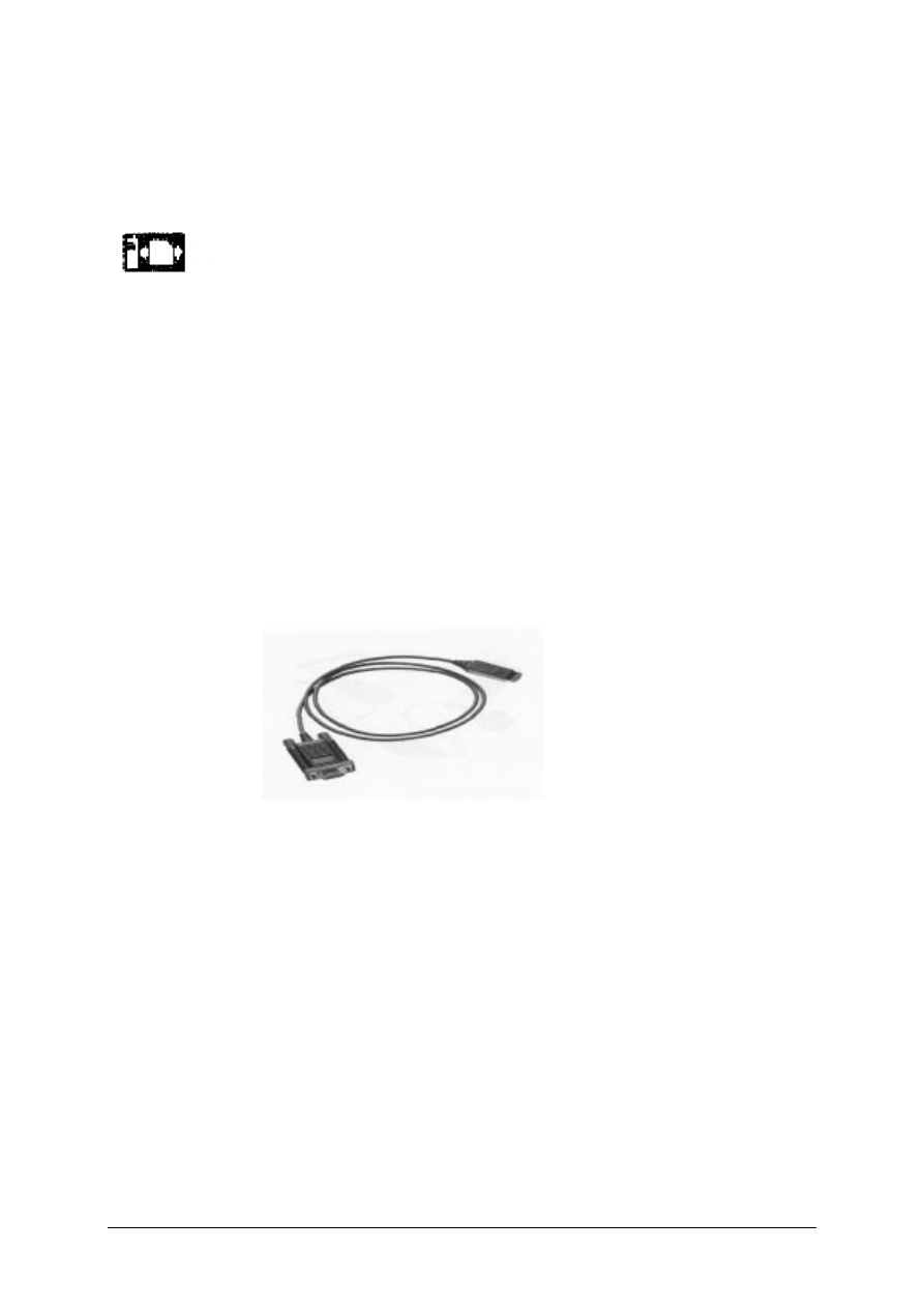
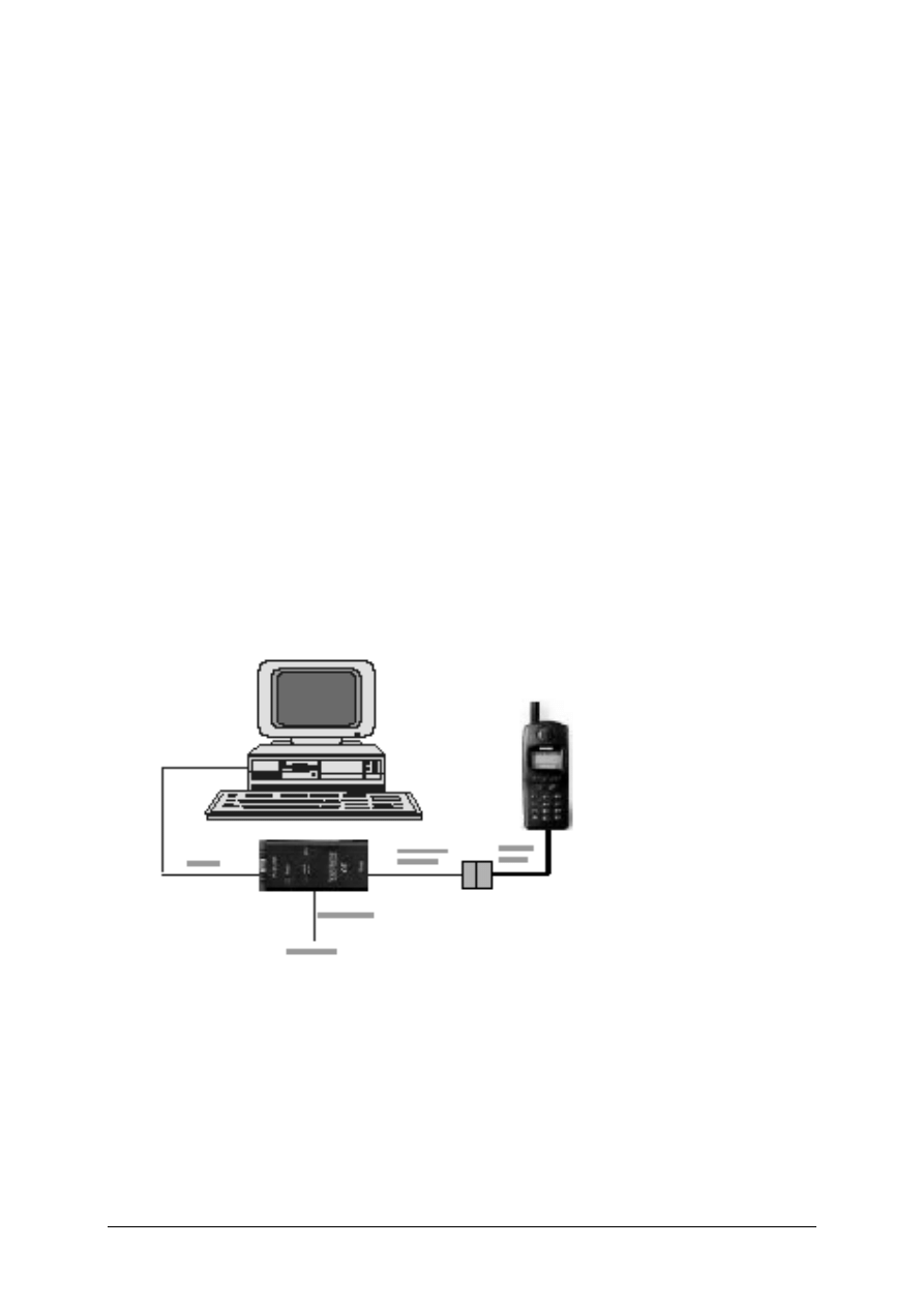
Built-in Modem.
C35i has an integrated modem for direct data communication using the data cable as shown in
Figure 1.5. C35 do not have the built-in soft modem for Data Service of GSM network.
FIGURE 1.5 DATA CABLE.

V1.0
6
Data Application Support
Modem driver conforms to V.25 command set, and transmission speed conforms ITU-T-
standard of V.22bis. (2400, 4800,and 9600 bits/sec).
Facsimile conforms to Service Class 1, group 3 and operate at 2400, 4800, 7200 and 9600 bit/s.
Data services via GSM network up to 9600 bps, and remote control using cellular AT commands
for C35i only.
Internet access via the C35i is possible with the inclusion of Wireless Application Protocol (WAP)
browser 1.1 .

V1.0
7
Level 2 Service Guide
Introduction
The chapter is intended to help you carry out repair up to Level 2 on the C35 series mobile
phone.
The repair for international version and Asian variants are identical unless otherwise noted,
therefore the description herein is confined to C35 only.
All repairs have to be carried out in an environment set up
according to ESD regulations defined in international standards.
ESD procedure is available from your Service Manager. Ask for
ASC/T001/98
Chapter
2

V1.0
8
C35 & C35i Technical Information
System
GSM Phase 2/Phase2+, Dual Band
EGSM 900, Class 4(2 Watt)
GSM 1800, Class 1(1 Watt)
Operating Voltage
3.6V
Size(LxWxH)
118 x 46 x 21 mm(without antenna)
Volume
88cm
3
including battery (approx)
Weight
116g including battery (approx)
Battery(Standard)
NiMH, 500mAH(Standard)
Li-Ion, 600mAH(Optional)
Standby time
1
50 to 180 hours (standard battery)
Talk time
1
90 to 300 minutes (standard battery)
Charging Time
Up to 1.5 hours with Rapid Charger
SIM support
Plug in card 1.8 V or 3V
Antenna
Non - retractable,
λ
/2, helical fixed.
Speech codec
Triple rate
Enhance Full Rate
Full Rate
Half Rate
Display
101 x 54 pixel graphical display with up to 5 lines
12 x 12 font size for Chinese
Keypad
12 numeric keys(10 numeric, #, *)
4 function keys(Send, End-ON/OFF, Menu, Phonebook)
2 multifunctional softkeys
Key Sound
Click/DTMF/None
Key Lock
Activation and Deactivation by #-key or
Automatic.
1
Actual time dependent on the network.

V1.0
9
Dialing
10 redial numbers,
Last 10 incoming with date/time stamp
Last 10 outgoing calls
Last 10 missed calls with date/time stamp
Ringer
On/Beep/Off
Up to 22 melodies and 5 ringing volume settings
(Melody Composer, Crescendo Ringing)
Volume
Adjustable in 4 levels during call via softkey
Silent Alert
Built-in vibrator
Phone Book
Storage depends on the SIM card capacity
Storage of up to 100 list in the phone (VIP)
SMS Support
MT, MO, CB
Predictive Text Input, Tegic T9.
Supplementary
Call Forwarding, Call Hold, Call Wait,
Services
Multiparty Conference, CLIP, CLIR, AoCC
AoCI, FDN, LND USSD and SAT.
Ciphering
A5/1 and A5/2 supported
PIN control
PIN 1 & 2 Code Control
Phone code
4 to 8 digit code
Network function
Automatic and manual network selection
Chipset
Siemens E – GOLD
WAP Browser
1
Version 1.1
Other Features
Clock / Alarm
Alarm List
2
Built-in modem
3
Calculator
4
Currency Converter
4 Games
7 User Profiles
1
Only for Model C35i.
2
Not available in C35 International version.
3
Not available in C35 International version.
4
Not available in C35 International version.

V1.0
10
Accessories:
1. Standard
Battery
L36880-N4001-A100
2. Optional
Battery
L36880-N4001-A101
3. Standard Charger
L36280-Z4-CXXX (Country Variant)
4. Travel Charger
L36880-N4001-A103 (EU) / A104 (UK)
Similar to standard charger with an universal input voltage from 90 ~ 240V
4. Desk Top Charger
L36880-N4001-A102
5. Belt
Clip
L36880-N4001-A113
6. Headset
L36880-N4001-A123
7. Antenna
Cradle
L36880-N4001-A110
8. Car Charger Cable
L36880-N4001-A108
9. Car Kit Portable
1
L36880-N3015-A117
10. Car Kit Comfort
L36880-N4001-A111
11. Car Handset
2
L36880-N3015-A123
12. Designer Cases
L36880-N4001-A119
13. Soft Data Link 3.0
L36880-N4001-A122 (Not for 3508i)
14. Data Cable
3
L36880-N3101-A102
15. Car Kit Professional Voice
L36880-N4001-A124
16. Data Cable Professional
4
L36880-N3101-A112
1
Same as C25(88)
2
Same as C25(88)
3
Same as C25(88)
4
Same as C25(88)
V1.0
11
General Information
Due to different requirements of the markets, the C35 series has different variants, which
broadly classified under International version and Asian version. Marketing name for
international version is C35 or C35i, whereas Asian version is named 3508 or 3508i.
The 3508 series is equipped with a graphic display which enable the telephone to display
CHINESE characters, either in Traditional font or Simplified font, beside the standard English.
Difference between C35(08) and C35(08)i
C35(08)i mobile software has WAP Browser 1.1 incorporated thus enabling user to surf the
Internet and it have built-in soft modem for GSM Data Service.
The differences between the C35 and C35i are the hardware and software. The memory size of
C35 is 16MB and that of C35I is 32MB.
There are also two variants for 3508, one without the WAP browser is 3508 and that with WAP
browser version 1.1 is 3508i. The different for ASIAN version is only mobile software.
Wireless Application Protocol, WAP.
Wireless Application Protocol takes a client-server approach that uses the in-built micro-browser
to make a request, in wireless markup language (WML), for information or service. The request
is passed to a WAP Gateway which then retrieves the information from a Internet server, in
HTML format, and translate it into WML. The requested information is then sent to from the
WAP Gateway to WAP client (mobile) using the available and most appropriate mobile network
bearer services.
Wireless Protocol Stack.
Wireless Application Environment (WAE)
Wireless Session Protocol (WSP)
Wireless Transaction Protocol (WTP)
Wireless Transport Layer Security (WTLS)
Wireless Datagram Protocol (WDP)
Bearers e.g. Data, SMS, USSD
TABLE 1..1 WAP PROTOCOL STACK
1. Wireless
Application
Environment
Defines the user interface on the phone. WAE contains the WML,WML script and the
wireless telephony application (WTA).

V1.0
12
2. Wirelss
Session
Protocol
Link the WAE to two session services – one connection oriented operating above the WTP
and a connectionless service operating above WDP.
3. Wireless Transaction Protocol
Runs on top of the datagram service and part of the standard suite of TCP/IP protocols, to
provide a simplified protocol suitable for low bandwidth mobile station.
4. Wireless Transport Layer Security
WTLS incorporates security features that are based upon the established Transport layer
Security (TLS) protocol standard, that include data integrity checks, privacy on the WAP
Gateway to client leg and authentication.
5. Wireless Datagram Protocol
Allows WAP to be bearer independent by adapting the transport layer of the under-laying
bearer. WDP presents a consistent data format to the higher layer on the WAP stack.
V1.0
13
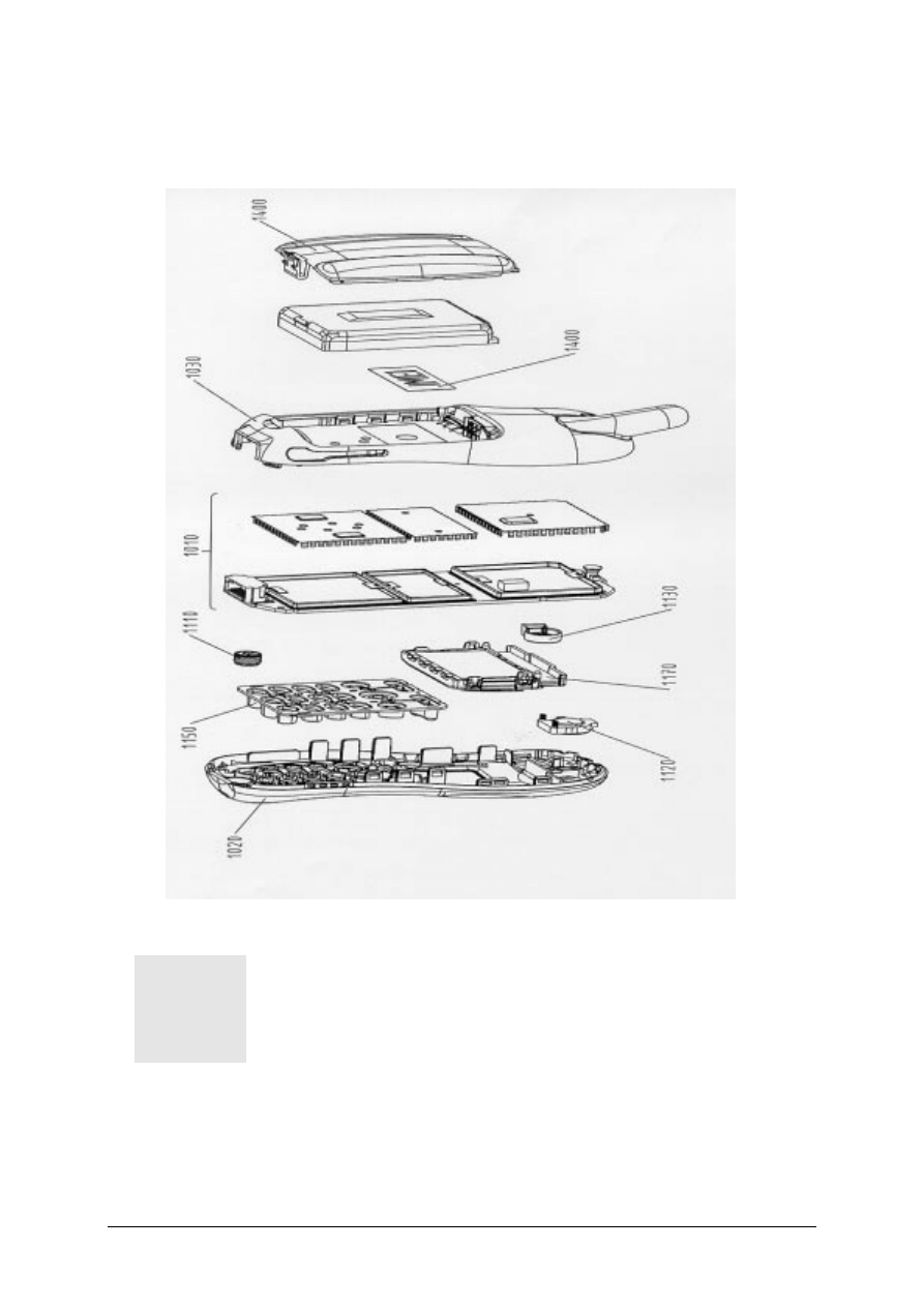
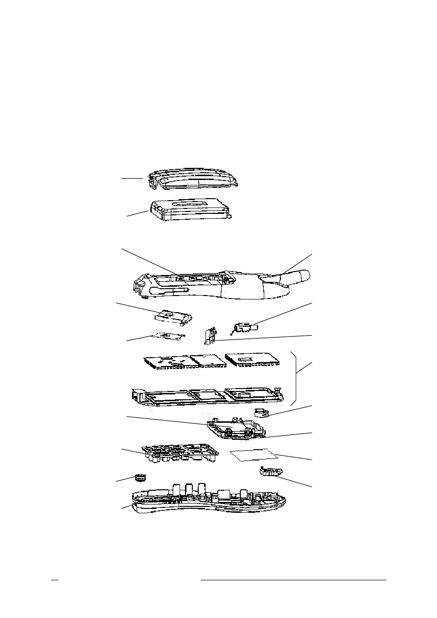
C35 Series Mechanical Diagram
FIGURE 2.1 C35 MECHANICAL DIAGRAM.
Please take note that the number(s) used here IS NOT the part
number, DO NOT used it in your spare parts purchase order.
A l w a y s r e f e r t o t h e S E R V I C E P A R T P R I C E L I S T
f o r y o u r s p a r e p a r t o r d e r .
1

V1.0
14
Mechanical Concept
Note: All numbers refer to mechanical drawing in Figure 2.1.
The mechanical concept of the C35 differs in various points from the one of the other Siemens
mobile telephones.
The first thing you will experience is how the housing is locked. In C35 no screws are used to
keep the housing closed. Also inside the telephone no screws are used anymore. To open the
housing, which is kept closed by catches only, a special opening tool has been defined.
For
details on disassembly tool please refer to Photo 2.3 in this chapter.
Inside, the C35 consists of just one board (1010) which carries display module(1170), control
part and RF section of the mobile.
The display module (1170) is connected to the board by a flexible cable which is inserted into a
plug. In case the display is defective electrically or mechanically it can be exchanged very easily.
C35 does have an external connector of a new type. Since S6 a so called “Molex”-connector
was used, which also offered the possibility to connect an external antenna to it. The new
“Lumberg”-connector which is used in C35 does not feature such a connection, because the
connector for external antenna is located at the back side of the upper end of the mobile, close
to the internal antenna (1130). As a consequence of this there is no need anymore for a RF
cable mounted to the board nor for a RF plug on it to connect this cable. This improves RF-
properties of the mobile and lowers production costs.
To be able to do measurements on and software update of the telephone, an adapter cable
between Molex and Lumberg connector will be available.
See photos in Additional Tools of
Chapter 3.
C35 series antenna is of a snap-in type which inserted into the lower case shell (1030). The
antenna can only be changed by opening up the C35 phone.
The C35 is a dual-band mobile operating on GSM900 and
GSM1800, the antenna is an integral part of the lower housing.
The keypad (1150), the microphone (1110) and the loudspeaker (1120) are mounted into the
upper case shell (1020). Make sure that the microphone and the earphone contact springs are
not dirty or damaged during repair process.
The dust protection frame and the display window are included in the display module(1170).
1
V1.0
15
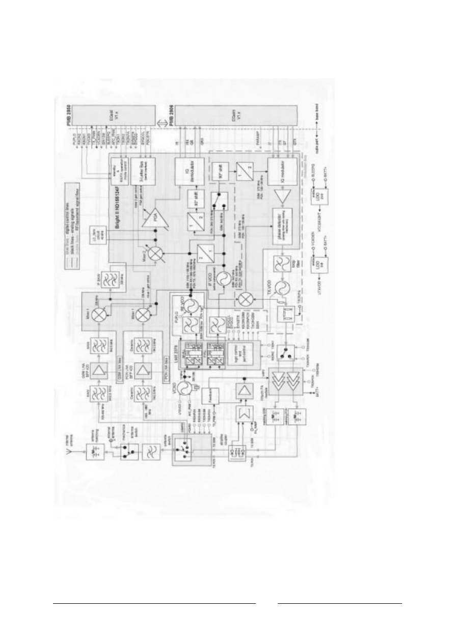
Hardware Concept – Block Diagram
FIGURE 2.2 C35 BLOCK DIAGRAM.

V1.0
16
Hardware Description
The handset consists of the following major integrated circuits:
1) E-GOLD – PMB2851E
This IC is a combination of microprocessor, signal processor and real-time clock.
The microprocessor part of this component is responsible for controlling the keyboard, SIM-
Card, Flash and RAM. Furthermore it controls the power saving, power up/power down of the
RF module and sets the amplification of the PA.
The signal processor part of PMB 2851E is responsible for processing the Rx I/Q signals
(filtering, equalizing, speech and channel decoding).
Furthermore it does the speech and channel encoding and the GSMK modulation of the Tx
I/Q signals. The Voice CODEC part is used to realize advanced features regarding coding of
the speech signal. These are:
•
Halfrate-Encoding
•
Halfrate-Decoding
•
Enhanced Fullrate Encoding
•
Enhanced Fullrate Decoding
•
Voice Activity Detection
•
Comfort Noise
2) GAIM – PMB2906
The GAIM (GAIM = GSM Analog Interfacing Module) provides the interface between the
analogue and its digital representation signals (Base-band I/Q, Voice-band, PA-control,
Voltage & Temperature Measurement - Charging control).
3) 13Mhz Ref Oscillator Circuit -
This circuit provides the following main functions:
•
Generate 13Mhz clock signal for Logic Circuits – SIN13M.
•
Generate 13Mhz reference signal for the PLL circuits for the Tx & Rx of GSM RF signal.
•
Received the frequency steering control AFC_PNM from the HiGOLD IC for fine tuning
of the Tx & Rx frequency.
•
Temperature dependent resistor sited near the 13MHz oscillator measure the
environment temperature.

V1.0
17
4)
Power Supply ASIC – D0767BA
This circuit provides the following main functions:
•
Control of switch on of the Mobile phone by ON/OFF button, Ext Power (Charger) or real
time clock.
•
Watchdog monitor – switch off the mobile phone if no proper Watchdog signal send from
HiGOLD IC.
•
Voltage supply to the logic circuits – 2.90V, 2.65V & 1.92V, Simcard & real time clock in
HiGOLD IC.
•
Switch on the linear regulator to supply the 2.8V for the13Mhz Oscillator circuit.
•
RESET signal for the logic circuit.
•
Charge control signal for switching the charge FET.
•
Low battery detector.
•
Over voltage protection.
5) Receiver Circuit – Bright II HD155124F
This circuit provides the following main functions:
•
Low Noise Amplifier (LNA) with a fixed amplification of +20dB to amplify the input RF
signal.
•
Mixer to mix down the RF signal to the Intermediate Frequency (IF)
•
Programmable IF amplifier with a dynamic range of 60dB ( -10dB ~+50dB in steps of
2dB).
•
Mixer to mix down the IF signal to the baseband, generating and inphase (I) and a
quadrature (Q) signal and feed the GAIM IC base-band signal, RX I/Q for the decoding
of the digital signal for the HiGOLD IC.
6) Transmitter Circuit – Bright II HD155124F
The GAIM IC generate the MOD I/Q base-band signal under the control of the HiGOLD IC
and feed the IQ modulator of the Bright II IC. The Bright II IC provides the IF synthesizer,
the I/Q modulator, prescaler to regulate the dual-band TX-VCO and feed the modulated GSM
signal to the PA.
The telephone support only 1.8V and 3V SIM card
For user with 5V SIM card, he need to upgrade the SIM card
through his service provider/network operator
1

V1.0
18
Power Supply Concept
The C35 has two main power inputs:
1. Battery voltage(3.6V) connected at the battery contact
2. Charging voltage(6.5V) delivered by the different charger type(see Accessory List) via the
Lumberg connector at the bottom of the telephone.
Since the battery voltage is supplying the power supply ASIC, it is always needed to operate the
phone.
You cannot switch on the handset if the battery voltage is not present.
From the battery voltage, all other supply voltages are derived and controlled by the power
supply ASIC.
The RF power amplifier is directly connect to the battery, a bad battery with high internal
resistance can cause malfunction of the C35 phone.
The Logic module uses 1.92V, 2.65V & 2.9V generated by voltage regulators inside the ASIC.
Furthermore, the ASIC generates the supply voltage for the SIM card and the RESET signal for
the logic devices.
The ASIC also checks the presence of the watchdog signal from the microprocessor and
provides the switching on functionality (ON_OFF button or Ignition signal).
Wrong polarity or battery voltage setting that exceed the +6.5V
could damage the phone.
Over-voltage Condition
•
Battery voltage
If the supply voltage rises above 6.2V, the phone will switch off and it cannot be switched on
again before the voltage is lower than 6.2V.
If the supply voltage rises above 7V, the phone can be damaged
•
Charging
Current
The charging current must not rise above 1A or a track fuse in the
phone will blow. As a result charging the battery will no longer by
possible.
1
1
V1.0
19
Be careful with NON-original SIEMENS accessories or chargers. Make sure that
the charging current is limited to value below 1A.
Battery
C35 series uses a Nickel Metal Hyride (NiMH) 500mAH battery pack as standard battery. It also
support the Lithium Ion 600mAH battery pack (For S35i phone) as optional battery for customer
want longer talk time.
PHOTO 2.32 C35 SERIES INSERTING BATTERY.
For C35, BATT+ has a voltage level from +3.0V to 5.5V, and a BATT_TEMP contact is used for
detecting abnormal increase in temperature of the battery.
If the temperature is too high or too low, there is a high probability
that the battery is not charged. To enable the charging process
again, battery and phone needs to cools down or warm up. Battery
replacement is not required.
A v o i d s h o r t i n g t h e b a t t e r y t e r m i n a l s .
Short Circuit Protection
For the Nickel Metal Hydride battery, a polyswitch in the battery pack protecting the battery from
short circuit and it should reset by itself after some time removing the short circuit.
For the Lithium Ion battery, it is short-circuit protected by an electronics fuse. The fuse will be
activated in case a too high current is drawn. This fuse will not reset automatically.
The resetting of the L-ion battery fuse can be done with either of the following procedures:
1. Insert the battery into the C35 and then connect the rapid charger to the phone. Wait for
approximately 10 second, then the mobile can be turned on again.
2. Plug the battery separately into the desktop charger. The fuse is reset immediately.
3. Insert the battery into the C35 and put the phone into the desktop charger. Wait for
approximately 10 second, then the mobile can be switched on.
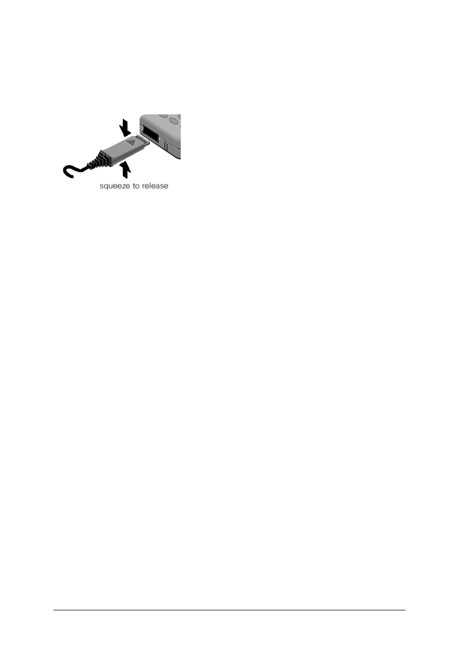
Charging
The battery can be charged when it is inserted into the phone. The charging process is
completely controlled by the mobile. Charging can be done with any of the following accessory:
1
V1.0
20
1. Rapid
charger
2. Travel
charger
3. Car
charger
4. Desktop
charger
PHOTO 2.33 INSERT CHARGER
Photo 2.33 shows the correct way of inserting and removing the charger plug.
Deep Discharge Battery
In case of a deeply discharged battery, the voltage of the battery is too low to operate the
charging circuit and the display controller, the phone can not be turned on and the normal
charging process can not be started. No charging symbol is visible in the display.
In this case, charging the battery is divided into two different steps, which have to be run
subsequently:
a) Trickle charge for C35 Phone
Trickle charge mode is automatically started if the battery voltage is below 3.0V when the
charger is connected to the mobile. The charging current in Trickle mode is appr. 10mA.
Trickle charge mode has to last minimum until the battery voltage has exceeded 3.2V,
then the phone will switch on and the charging icon appear. During trickle charge the
charging symbol will not be visible and the telephone can not be turned on. This is
because the battery voltage is too low to operate the telephone.
Action:
Insert battery into handset and connect travel charger to the telephone. If within 4 hours
the battery voltage is high enough again, the charging symbol will come up.
If the battery is discharged very deeply, the symbol may not come up and the trickle
charge time possibly has to be extended up to 24 hours.
b) Normal charge
When the battery voltage is above the a.m. value (e.g. by trickle charge) the mobile will
start the normal charging mode and show a charging symbol in the display. * Always
normal charge a new battery or a deep discharged battery for more then 12 hours before
first use.
Action:
Connect charger to the telephone (
see section on Charging).
V1.0
21
The charging symbol will come up as an indication that the normal charging process has
been started by the mobile.
Mobile Phone C35 Spare Parts Level 2
SIM Card Reader
with
Card Holder
L36334-Z97-C111
SIM Card Holder
L36334-Z97-C112
Display module
L36851-Z1508-A51
Keypad
L36158-A33-B75
Microphone
L36254-Z6-C82
Upper Case Shell
L36158-A33-B....
Antenna
L36158-A33-B161
Vibra-Alert Unit
L36453-Z5-C77
Battery Contact Spring
L36334-Z97-C113
RF Control Board
L36880-Q4050-B201
Buzzer Sealing
L36158-A33-C260
Display Cover
L36851-A33-C101
Display Sealing
L36158-A33-C103
Earphone
L36212-Z3-C34
Battery Cover
L36158-A33-B....
Battery NI-MH
L36145-K1310-X125
Lower Case Shell
L36880-A33-B....
L36158-A33-B....see Spare Part
V1.0
22
Disassemble the C35
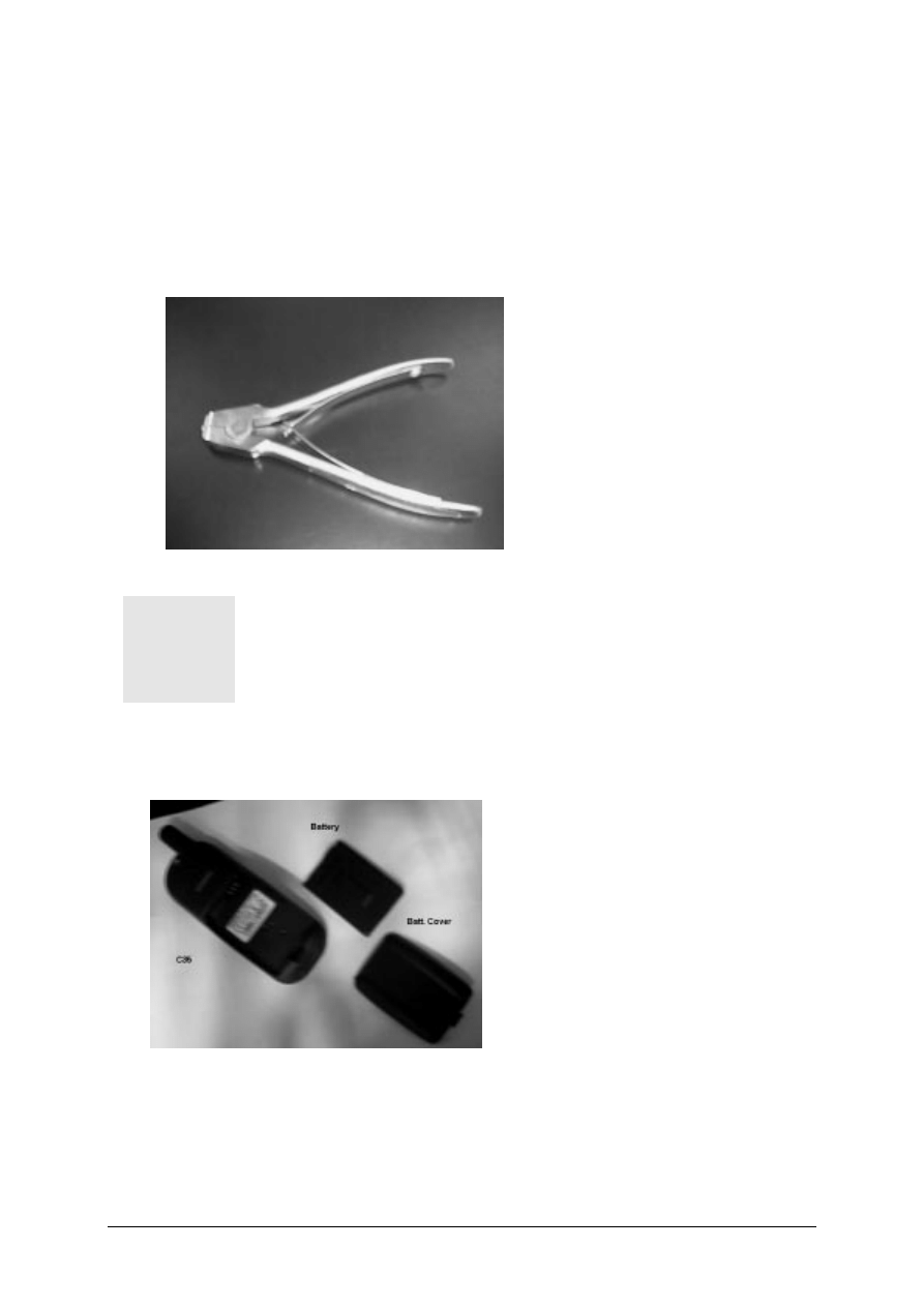
A case opener is needed to disengage the latch of the C35 casing.
PHOTO 2.3 C35 CASE OPENER
The part number for this mandatory tool is F30032-P46-A1
Refer to ANNEX B of Chapter 3 for Service Equipment List.
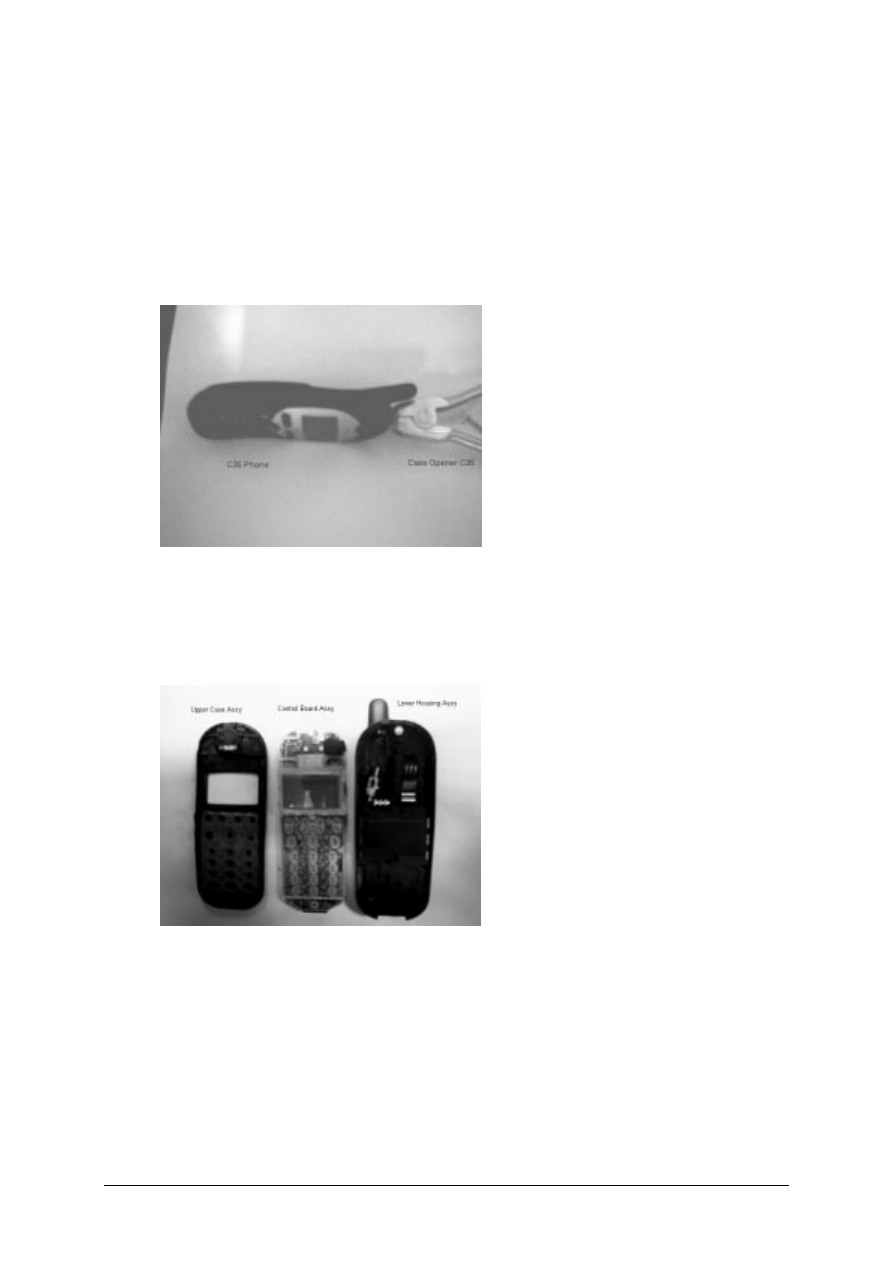
STEP 1:
Remove the battery cover then the battery as shown in PHOTO 2.4
PHOTO 2.4 DISASSEMBLE C35 – STEP 1
1
V1.0
23
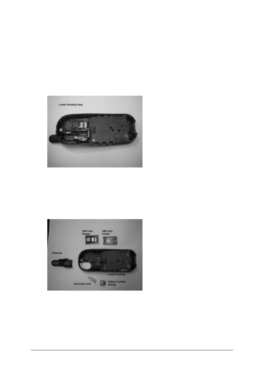
STEP 2:
Open the housing with the opening tool and carefully pull the lower housing section off as
illustrated in PHOTO 2.5
PHOTO 2.5 DISASSEMBLE C35 – STEP 4
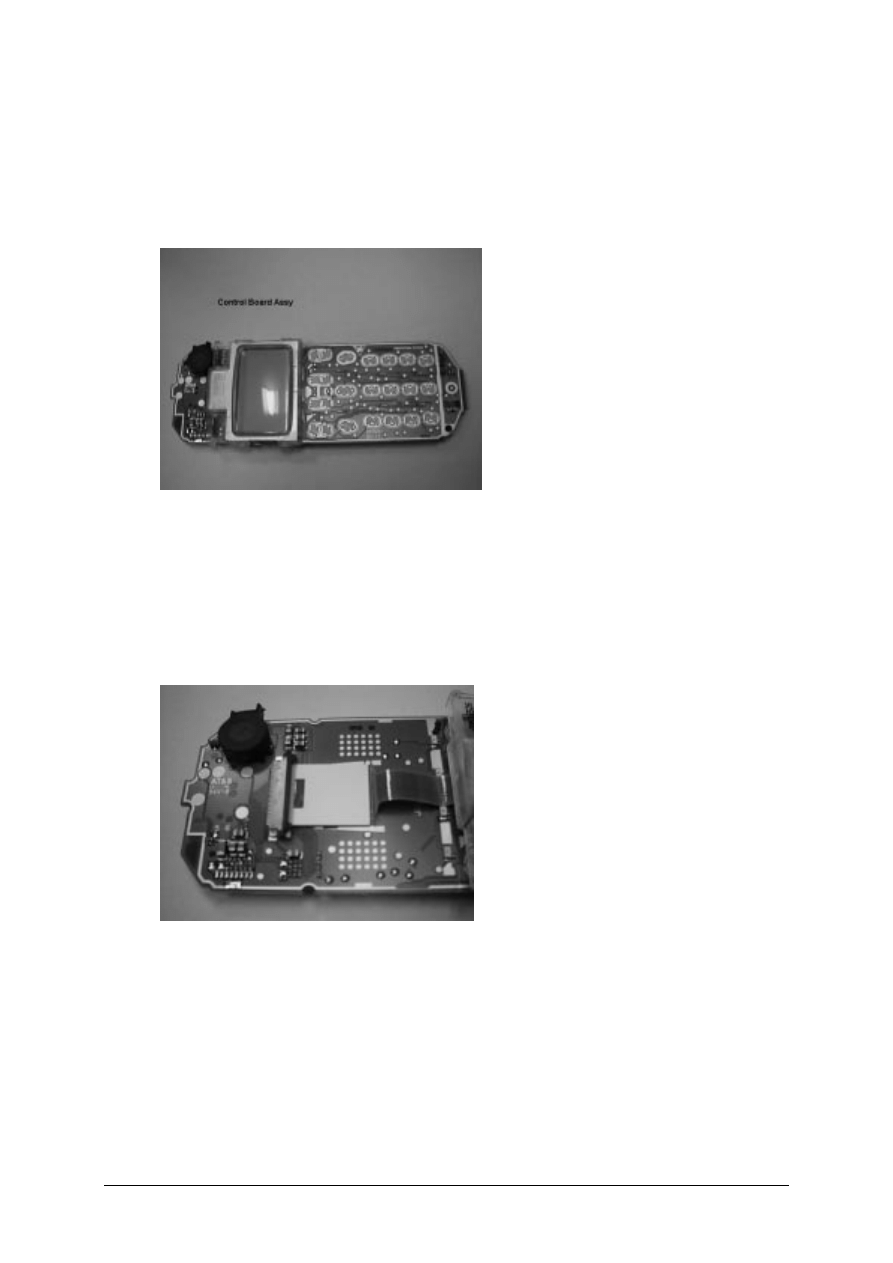
STEP 3:
Use the Case Opener carefully disengaged the catches of the Lower housing and Upper
housing to separate the housing and the Control Board Assembly as in PHOTO 2.6
PHOTO 2.6 DISASSEMBLE C35 – STEP 3
V1.0
24
Disassemble/Assemble of the Lower Housing Assembly
STEP 1:
Open the housing with the opening tool and carefully pull the lower housing section off as
illustrated in PHOTO 2.7
PHOTO 2.7 Lower Housing Assy – STEP 1
STEP 2:
Remove in sequence by hand the SIM Card Holder, SIM Card Reader, Battery Contact Spring,
Vibra-Alert Unit and the Antenna as illustrated in PHOTO 2.8
PHOTO 2.8 Disassembly Lower Housing – STEP 2
For Remove/Install the Antenna, watch out for the two catches on the Lower Housing. For install
of the other parts, watch out for the guide notches. For the assembly of the Lower Housing just
reverse the sequence for the disassembly.
V1.0
25
Disassemble/Assemble the Control Board Assembly
STEP 1:
Open the housing with the opening tool and carefully pull the lower housing section off as
illustrated in PHOTO 2.9
PHOTO 2.9 Control Board Assy – STEP 1
STEP 2:
Unlock the catches of the Display Module from the Control Board and move the display module
to the lower part of the PCB. Lift up carefully the retaining clip of the display connector on the
Control Board as illustrated in PHOTO 2.10
PHOTO 2.10 Disassemble Control Board Assy – STEP 2
V1.0
26
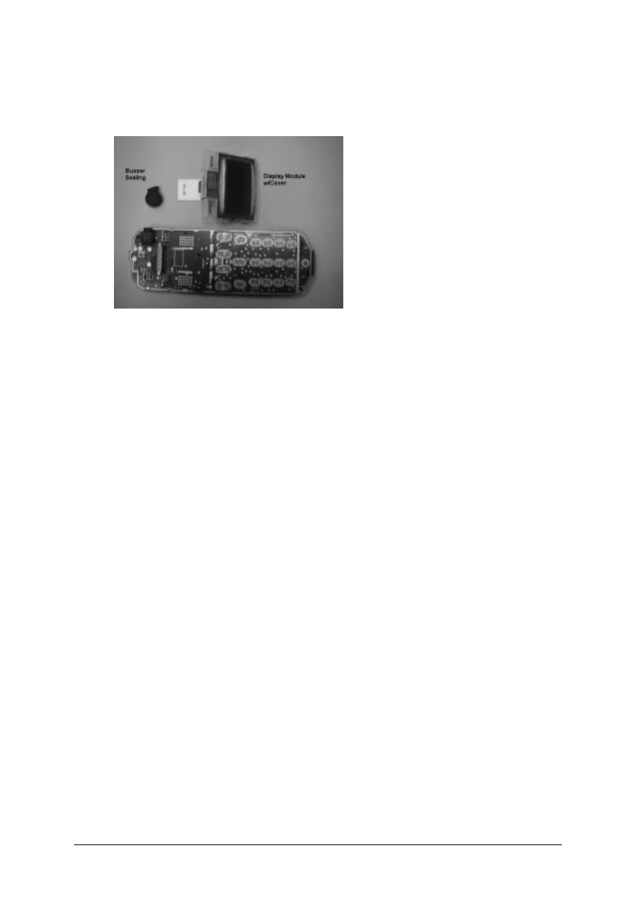
STEP 3:
Remove the Display Module and the Buzzer Sealing from the Control Board as illustrated in
PHOTO 2.11
PHOTO 2.11 Disassemble Control Board Assy – STEP 2
For Remove/Install the display module, watch out for the catches on the display module and the
guide hole of the PCB. For the assembly of the Control Board assembly just reverse the
sequence for the disassembly.
V1.0
27
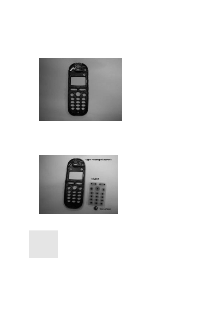
Disassemble/Assemble of the Upper Housing Assembly
STEP 1:
Open the housing with the opening tool and carefully pull the lower housing section off as
illustrated in PHOTO 2.12
PHOTO 2.12 Upper Housing Assy – STEP 1
STEP 2:
Remove the Keypad by hand and use a fine point metal tweezers to remove the microphone as
illustrated in PHOTO 2.13
PHOTO 2.13 Disassemble Upper Housing – STEP 2
The loudspeaker is glued to the upper housing section by a foam
covered with glue on both sides. When you remove it, the foam
will be damaged. Please use new loudspeaker for assembling
Upper Housing Assembly.
For assembly of a new Upper Housing install a new earphone first, watch out for the orientation.
For install of the other parts just reverse the sequence for the disassembly.
1
V1.0
28
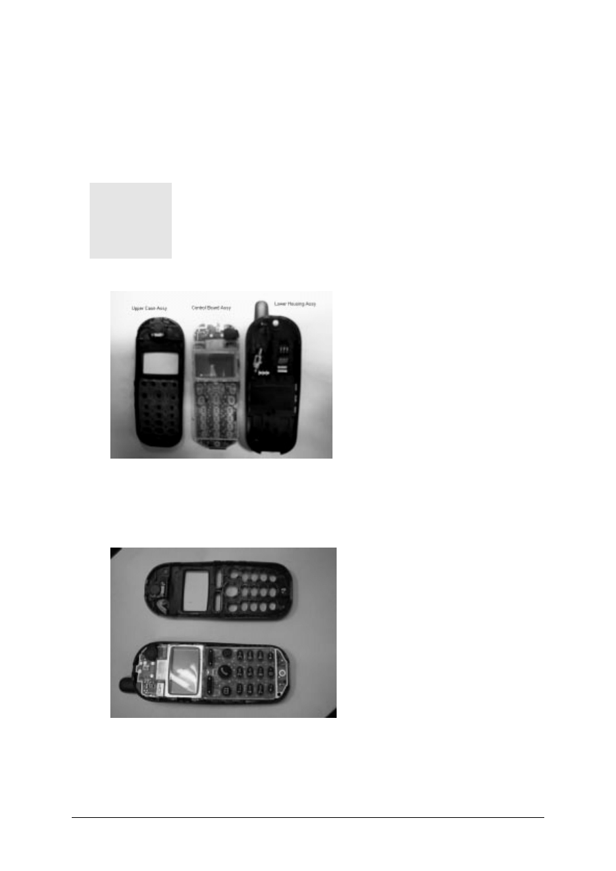
Assemble the C35
STEP 1:
Check that the Lower Housing Assembly, Control Board Assembly and Upper Housing
Assembly are in good order. Check if the Buzzer sealing was installed on the Control Board.
N e w U p p e r a n d L o w e r C a s i n g m u s t b e u s e d . A l l
c o n t a c t p i n s m u s t n o t b e d i r t y , d a m a g e d o r b e n t !
I f a n y p a r t i s n o t O . K p l e a s e r e p l a c e i t w i t h a n e w
p a r t .
STEP 2:
Place the Control Board Assembly in the Lower Housing Assembly and then place the keypad
on top of the Control Board as illustrated in PHOTO 2.15. You may insert a battery in this step to
test that the phone can be switch on.
PHOTO 2.15 ASSEMBLE C35 – STEP 2
1
V1.0
29
STEP 3:
Close the device by putting on the Upper casing section as illustrated in PHOTO 2.16. Hold the
phone and use both hands to close the casing starting from the catches at the top part near the
antenna, watch out for leaving any finger marking on the display screen.
D o n o t p l a c e t h e p h o n e o n t h e
t a b l e t o c l o s e u p t h e h o u s i n g a s
t h e A n t e n n a m a y b e d a m a g e .
A L L C A T C H E S M U S T E N G A G E
C O M P L E T E L Y !
PHOTO 2.16 ASSEMBLE C35 – STEP 3
STEP 4:
Remove old IMEI label from the old housing using a hair-dryer for re-use of the IMEI label or
paste the new IMEI label supplied for control board replacement. Insert the battery and put back
the battery cover. Ready for testing.
PHOTO 2.17 ASSEMBLE C35 – STEP 4
1
V1.0
30
RS232 Port
Adaptor-Cable -Bootadptor
Bootadptor
AC Adaptor
Mobile Software Programming
Model before C25 and C35, software used for the mobile are similar except for their differences
in the language group. Customer specific values (e.g. ringing tones etc) are seldom, but there
were some, were included in the common mobile software.
C25 and C35 has changed. There is still a common mobile software available which is divided
into language groups. However, this software does not contain the specific settings, such as
ringing tones, greeting text, short dial list etc., required by the operator(s) or service provider(s).
Therefore, it is not uncommon to have some menu item(s) differ in different variants or are not
visible at all. These settings are stored in different memory area of the mobile and will be
activated depending on the customer specific model or variant of the phone by a separate test
step during the production process.
Due to this separation of common mobile software and customer specific initialization, it is
possible to fulfill the demands of the market requiring customization and flexibility.
As a consequence the software programming process in the LSO is divided into two different
steps as followed:
1. Software update to actual version and appropriate language group
2. Programming of CUSTOMER SPECIFIC INITIALIZATION
Mobile Software Updating
The software of the mobile, C35 series, is loaded from a PC directly. Hardware interconnection
between the mobile and the PC is shown in Figure 2.6
FIGURE 2.6 C35 SERIES SOFTWARE PROGRAMMING SETUP
Because of the new type of external connector used in C35 (Lumberg type) an additional
adaptor cable between mobile and boot adaptor is required. Table 2.1 listed all the hardware
requirements

V1.0
31
If you use the C35 battery dummy, then make sure that the power supply voltage is correctly
adjusted 4.0V & 3A current rating.
Description
Part No.
Adaptor-Cable-Bootadaptor, C35/C35
V30146-A5004-D
Boot Adaptor
L24857-F1006-A30
IBM Compatible PC – Pentium
-
TABLE 2.1 EQUIPMENT LIST FOR SOFTWARE PROGRAMMING.
V1.0
32
SOFTWARE IS A DOS-BASED PROGRAM, IT IS
ADVISABLE TO DO THE SOFTWARE UPGRADE IN DOS
ENVIRONMENT.
Languague Groups
There are over 20 languages for the C35i series in total. These languages are divided into
groups as follows
C35i / 3508i
Group
Languages
1
English, German, French, Italian, Dutch, Swedish,
Finnish, Norwegian, Danish.
2
English, German, French, Italian, Dutch, Swedish,
Finnish, Norwegian, Danish.
3
English, German, French, Italian, Spanish, Catalan,
Portugese, Dutch.
4
English, German, Hungarian, Polish, Russian, Bulgrian,
Czech, Slovakian.
5
English, French, Italian, Arabic, Greek, Turkish, Hebrew,
Bahasan Malaysia, Bahasan Indonesia.
8
English2, Chinese Simplified, Chinese Traditional.
Note: Tegic- T9 Input method support in for the languages BOLD.
TABLE 2.2 SOFTWARE LANGUAGE GROUPS.
T h i s i n f o r m a t i o n i s s u b j e c t t o c h a n g e !
Contact your Service Manager for the order number of the
right version of mobile software for your market.
The mobile software file is named using this convention:
e.g.
C3i_0501
Î
Version = 05; Language Group = 1
C3i_0506
Î
Version = 05; Language Group = 6.
1
1
C35_(Version)(LG).EXE
V1.0
33
This executable file needs a definition or init file, named SWUP.INI, to define the message
language preferences and the hardware communication port set up.
The content of this file consists of the following text:
Where x is the number that corresponds to the serial port that is used, either 1, 2 or 3.
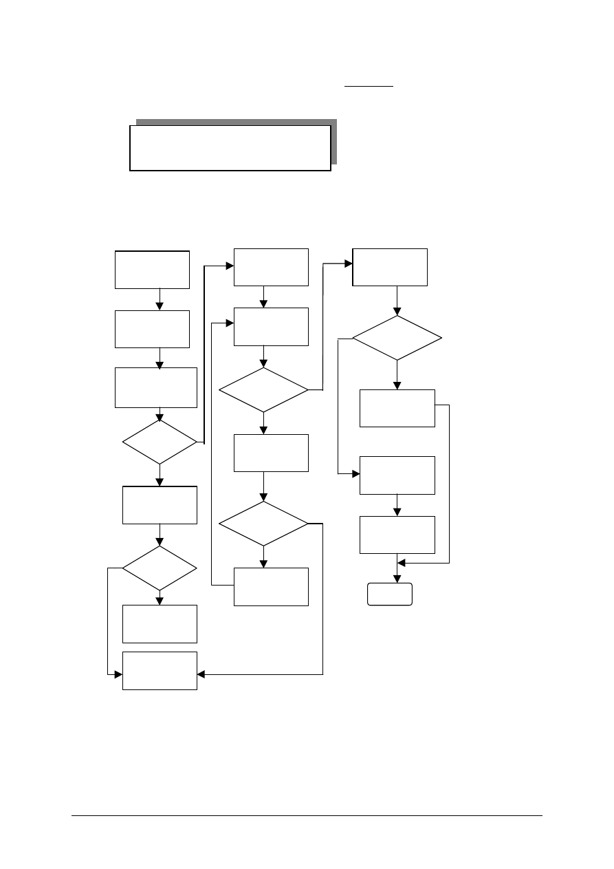
Flow chart 2.1 illustrates the software programming process.
FLOWCHART 2.1 SOFTWARE PROGRAMMING. PROCESS
No
Yes
Yes
No
No
Yes
Yes
No
Yes
No
Plug in the Boot
Adaptor to the
PC and Mobile
Connect the AC
adaptor to the
Boot Adaptor
Power up Boot
Adaptor &
Check LED
OK
?
Check AC
Adaptor
OK
?
Faulty AC
Adaptor
Faulty Boot
Adaptor
Power up the PC
in DOS
environment
Execute the
“Mobile S/W”
Error
?
Check
H/W setup =
S/W settings.
OK
?
Software
upgrading in
progress
Correct settings.
Error
?
Test Mobile
Take note of error
and repeat
process again
Feedback Error
to ICP CD ASC
END
Language=English
COM=x
V1.0
34
Customer Specific Initialization
Refer to the Customization Guide
L S O h a s t o m a k e s u r e t h a t a f t e r r e p a i r t h e
c u s t o m e r g e t s t h e m o b i l e w i t h c o r r e c t v a r i a n t
s p e c i f i c i n i t i a l i z a t i o n .
F o r m o r e i n f o r m a t i o n a b o u t t h e c o n f i g u r a t i o n
t o o l , r e f e r t o S e r v i c e I n f o r m a t i o n d a t e d 3 0
t h
A p r i l 1 9 9 9 , o r c o n t a c t y o u r S e r v i c e M a n a g e r .
International Mobile Equipment Identity, IMEI
The mobile equipment is uniquely identified by the International Mobile Equipment Identity, IMEI,
which consists of 15 digits. Type approval granted to a type of mobile is allocated 6 digits. The
final assembly code is used to identify the final assembly plant and is assigned with 2 digits. 6
digits have been allocated for the equipment serial number for manufacturer and the last digit is
spare.
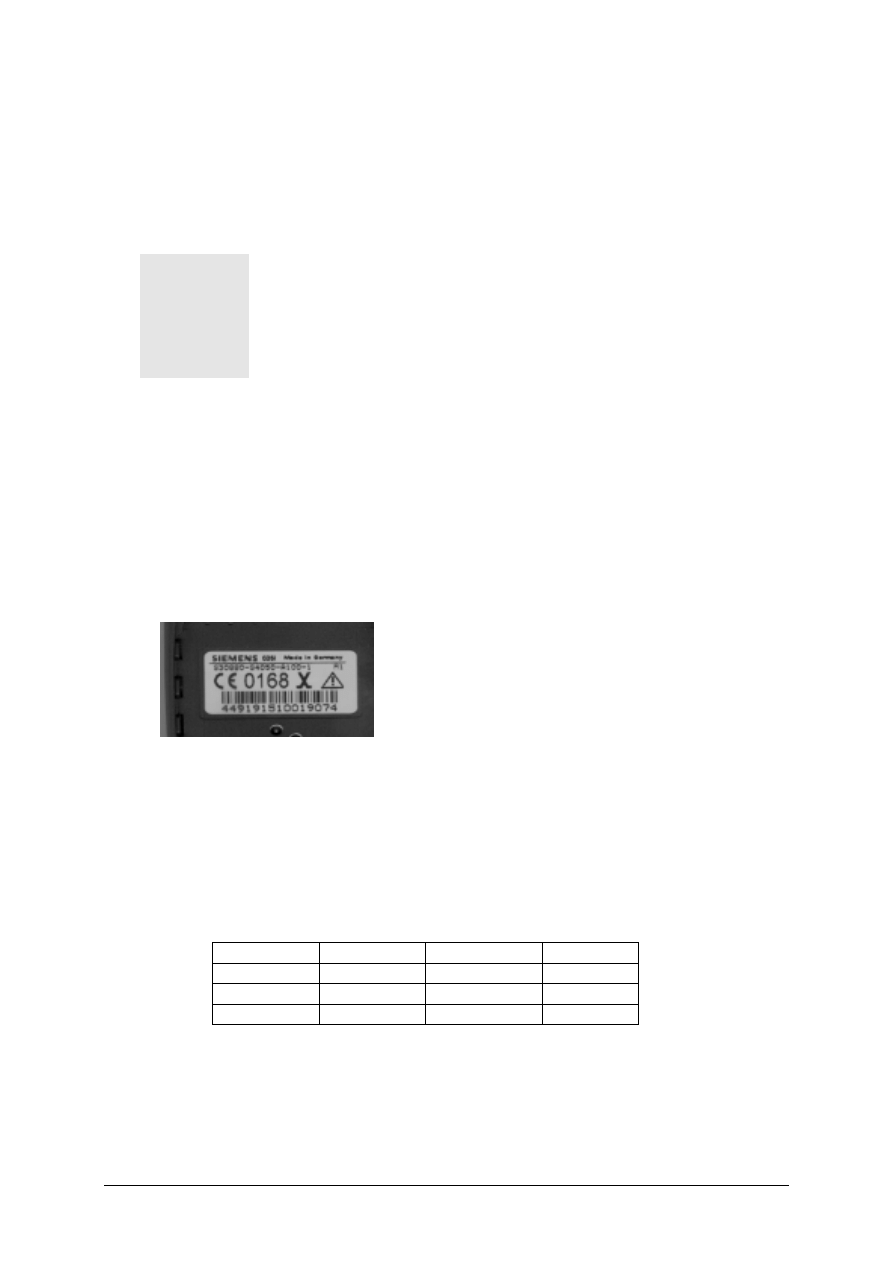
C35 series IMEI label is accessible by removing the battery. It is illustrated in Photo 2.18.
PHOTO 2.18 C35 SERIES IIMEI LABEL
Re-use of IMEI label is possible by using a hair-dryer to remove the IMEI label.
On this IMEI label, Siemens has also includes the date code for production or service, which
conforms to the industrial standard DIN EN 60062. The date code comprises of 2 characters:
first character denotes the Year and the second character denotes the Month. Fr example, the
IMEI above show date code M1.
Year
Date Code
Month
Date Code
1999
L
December
D
2000
M
January
1
2001
N
February
2
TABLE 2.3 DIN EN 60062 DATE CODE
V1.0
35
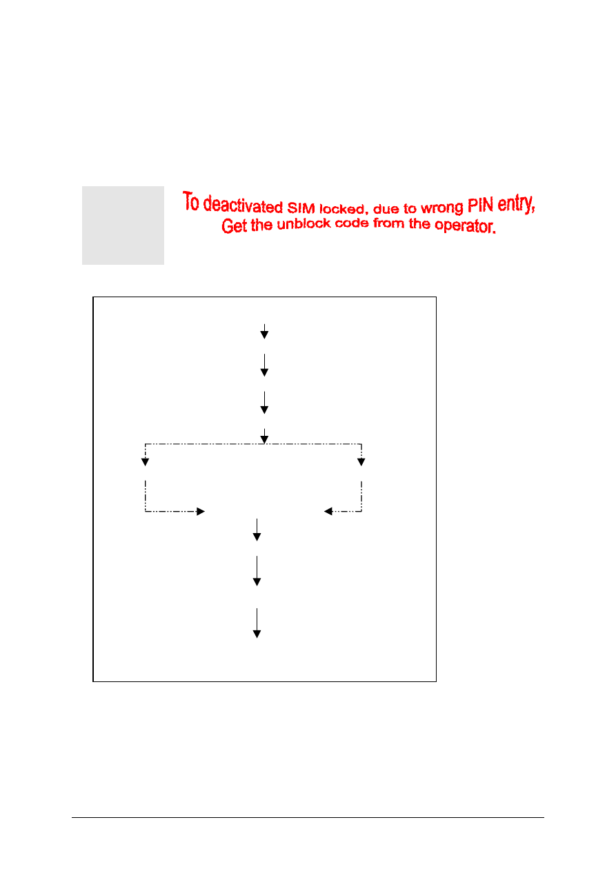
Phone Unblocking
When the phone is disable due to wrong entry of PHONECODE, it can be re-activated by
entering the right unblocking code. This unblocking code is derived from the IMEI number of the
mobile.
The unblocked code, also known as Master Phone Code, has to be entered in the following
format:
* # 0 0 0 3 * - - - - - - - - #
The Master Phone Code can be obtained by:
1. Fax to Siemens Hotline in Germany
Siemens AG
ICP CD SH
World Service Center, Bocholt, Germany
+49-2871-91-3007
2. Fax to Siemens Hotline in Singapore
Siemens Advanced Engineering Pte Ltd
ICP CD ASC
Ms Ginny Siew
+65-842-6641
3. Internet Solution
A password protected homepage where LSO can enter IMEI number of a disable phone. The
generated Master Code will then be presented for unblocking purpose. This service is offered to
all LSOs.
V1.0
36
PHOTO 2.19 INTERNET PAGE
PHOTO 2.20 INTERNET PAGE: MASTER PHONE CODE
Contact your Service Manager for more information regarding
setting up of the INTERNET SOLUTION & its installation
procedure, ASC/T002/98.
1
V1.0
37
Siemens Service Equipment
U S E R M A N U A L
Introduction
Every LSO repairing Siemens handset must ensure that the quality standards are observed.
Siemens has developed an automatic testing system that will perform all necessary
measurements. This testing system is known as
S i e m e n s M o b i l e S e r v i c e E q u i p m e n t
Using this system vastly simplifies the repair of the phones and will make sure that:
1. All possible faults are detected
2. Set which pass the test will be good enough to return to customer.
Starting from the P35 Series, Siemens will introduce a simpler and faster testing platform for
testing a repaired Siemens mobile phone. The testing platform are either base on R&S CMD
53/55 or CTS55 GSM test set.
There is also test software under development for testing with the Wavetek 4201S and the 4107
GSM test set.
A Level 2.5 service software is also under development for more elaborate testing for the repair
for the P35 series mobile phone.
THE LSO WILL HAVE TO PURCHASE THE SYSTEM, CHOOSING BETWEEN
THE COMPLETE PACKAGE OR SUB-SET OF IT
.
A F U L L Y A U T O M A T I C T E S T P R O C E D U R E I S O N L Y
P O S S I B L E I F T H E C O M P L E T E S Y S T E M I S
I N S T A L L E D .
Make sure that your CTS firmware is Version 3.01 or higher. For CMD
55 it must be Version 4.03 and higher. Please check with the Service
Info SB_0500 for the CTS/CMD Hardware Options.
Chapter
3
1
1
V1.0
38
R&S CMD55 Test Station
R&S CTS55 Test Station
V1.0
39
Wavetek 4201S Test Station
Other equipment
One Pentium MMX Window 95/98 PC with a serial port to connect to the GSM test set through
the PC serial cable provided for the GSM test set.
One Test SIM card and a fully charged battery for used with the mobile phone model.
Additional RF connector will be needed for setup using Wavetek 4107 test set and Wavetek
Antenna Coupler.
For LSO Test Station setup base on the Wavetek 4107 test set, you need a TNC(male) to
SMA(female) connector. For the Wavetek Antenna Coupler, you need a TNC(female) to
SMA(female) connector. The part number for the connectors will be announced soon.
For Wavetek GSM test set
For Wavetek Antenna Coupler
V1.0
40
Software Installation
Before executing the test software, it is important to ensure that the software configuration
matches that of the hardware set up. Each GSM Tester will have a specific test software. The
test software are name CMD
_
GO, CTS
_
GO and for Wavetek test set, CAT4200 respectively.
First, copy the installation software for the specific GSM tester to a temporary directory on the
harddisk of the Window PC and then Run the Setup from the first sub directory – Disk1 for
CMD_GO test software.
After the installation for the test software, RUN the Test software and check the configuration
setting for the Serial port.
V1.0
41
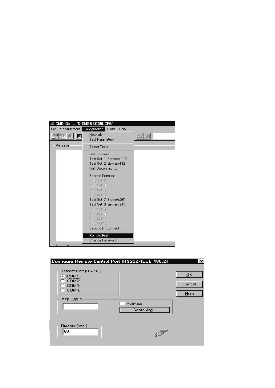
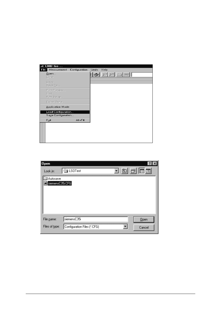
Configuring the test software
For each model of the P35 series mobile phone, Siemens will distribute the testing configuration
file for the specific test station. For testing the phone, just go to the File menu and select Load
Configuration.
V1.0
42
Running the test sequence
Make sure that your CTS firmware is Version 3.01 or higher. For
CMD 55 it must be Version 4.03 and higher. Please check with the
Service Info SB_0500 for the CTS/CMD Hardware Options.
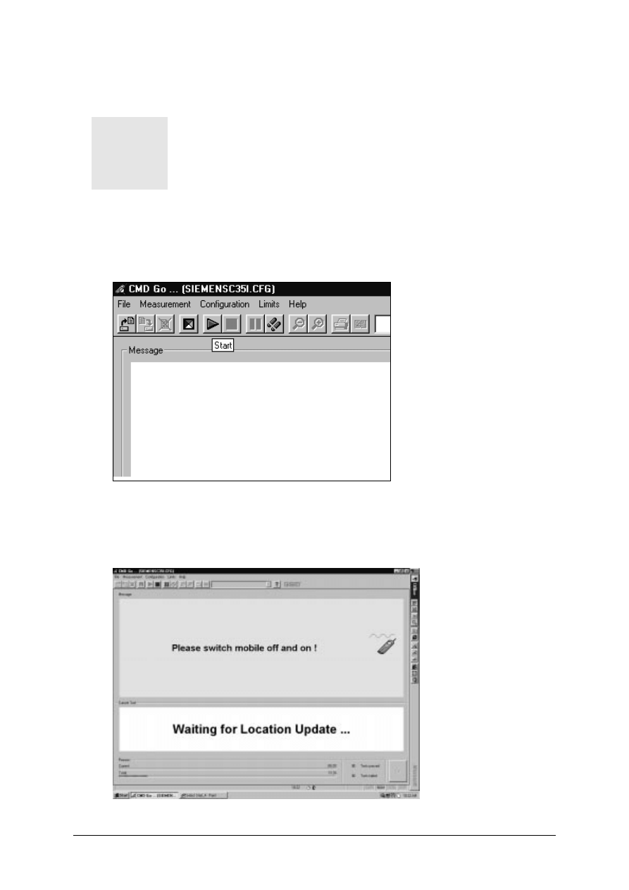
Insert a Test SIM card and a fully charged battery into the Siemens mobile phone and place it
onto the phone holder on the Antenna Coupler. Switch the RF switch to INT ANT position and
select the Start button to run the test sequence in the configuration file.
Follow the instruction on the screen and switch on the phone. The mobile phone will start
Network Search and doing Location Update to the GSM test set through the off-air signal from
Antenna Coupler.
1
V1.0
43
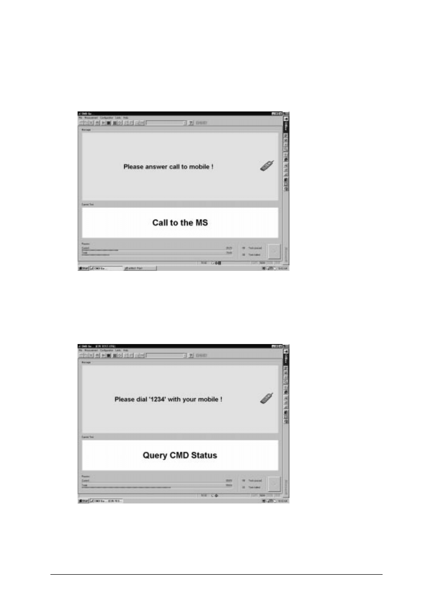
Next, the GSM test set will initial a call to the mobile phone through the Antenna Coupler. Press
the Call key when the mobile phone ring, and the GSM test set will start Tx Power
measurements on the GSM and GSM1800 channel specified by the configuration setting.
Next, the GSM test set will end the call to the mobile phone and the screen will prompt for
Dialing from the mobile phone. At this test step, please move the mobile phone to the Antenna
Cradle and switch the RF switch to EXT ANT position. Once the mobile phone log to the GSM
test set, dial 1234 and the Send key.
V1.0
44
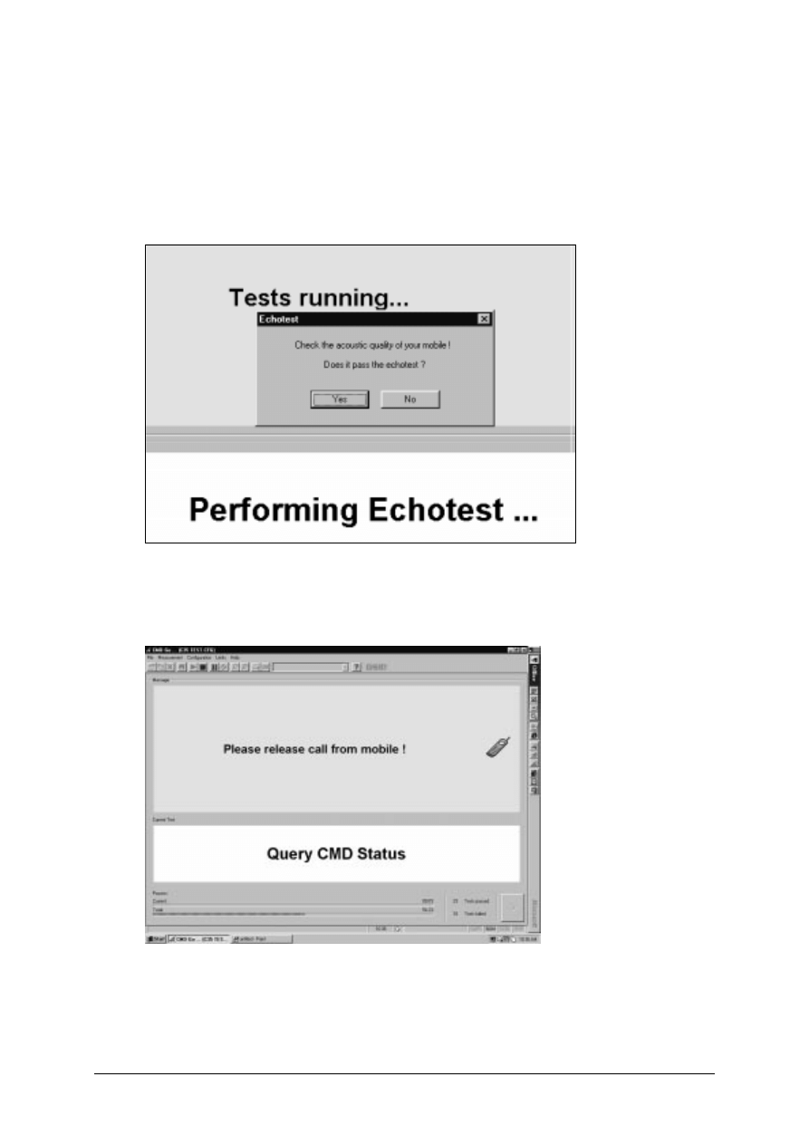
The GSM test set will make Tx Power measurements, Rx BER measurement, Echo Loop test
on the GSM and GSM1800 channel specified by the configuration setting. There will be 2 Echo
Loop Back test for checking the speech quality – one for GSM and one for GSM1800. Speak
into the mobile phone when prompted and listen the voice after appr. 1 second and check the
speech quality. If not O.K, it may be microphone or the earphone defective.
The last test is Disconnect Call from the mobile phone. Press the End Call key and the test
sequence will end.
V1.0
45
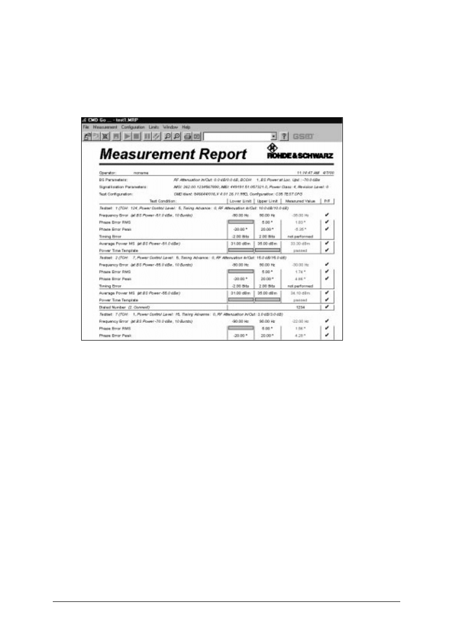
A measurement report screen will show up and a hardcopy can be printed if a printer is
connected to the PC. To close the measurement report screen, click the third button from the
left.
Once the mobile phone pass all the test steps, please make a check for all the key and the
display. After this we can confirm on the proper functioning of the mobile phone after repair and
return the phone back to the customer.
V1.0
46
ANNEX A
Cable Specifications
1. PC to NGSM(Power Supply)
Depending on the type of serial connector that is used by the PC. The cable layout for both
9pins and 25pin are listed below:
Computer:
Sub-D 25 pins
NGSM:
Sub-D 25 pins
TxD
Pin 2
RxD
Pin 3
RxD
Pin 3
TxD
Pin 2
RTS
Pin 4
DCD
Pin 8
DCD
Pin
8
RTS Pin
4
CTS
Pin 5
DTR
Pin 20
DSR
Pin 6
DTR
Pin 20
DTR
Pin 20
CTS
Pin 5
DTR
Pin 20
DSR
Pin 6
GND
Pin 7
GND
Pin 7
TABLE A.1 D25 TO D25 CONNECTION
Computer:
Sub-D 9 pins
NGSM:
Sub-D 25 pins
TxD
Pin 2
RxD
Pin 3
RxD
Pin 3
TxD
Pin 2
RTS
Pin 7
DCD
Pin 8
DCD
Pin
1
RTS Pin
4
CTS
Pin 8
DTR
Pin 20
DSR
Pin 6
DTR
Pin 20
DTR
Pin 4
CTS
Pin 5
DTR
Pin 4
DSR
Pin 6
GND
Pin 5
GND
Pin 7
TABLE A.2 D9 TO D25 CONNECTION
2. PC to CMD 53 or CTS 55
Depending on the type of connector used for the PC serial interface, two different type of
cables can be used:
Computer:
Sub-D 25 pins
CMD / CTS:
Sub-D 9 pins
TxD
Pin 2
RxD
Pin 2
RxD
Pin 3
TxD
Pin 3
DSR
Pin 6
DTR
Pin 4
GND Pin 7
GND
Pin 5
DTR
Pin 20
DSR
Pin 6
CTS
Pin 5
RTS
Pin 7
RTS
Pin 4
CTS
Pin 8
TABLE A.3 D25 TO D9 CONNECTION
V1.0
47
Computer:
Sub-D 9 pins
CMD / CTS:
Sub-D 9 pins
RxD
Pin 3
TxD
Pin 2
TxD
Pin 2
RxD
Pin 3
DSR
Pin 6
DTR
Pin 4
GND Pin 5
GND
Pin 5
DTR
Pin 4
DSR
Pin 6
CTS
Pin 8
RTS
Pin 7
RTS
Pin 7
CTS
Pin 8
TABLE A.4 D9 TO D9 CONNECTION
3. PC to Adaptor Box
Computer:
Sub-D 9 pins
Adaptorbox:
Sub-D 9 pins
TxD
Pin 2
RxD
Pin 3
RxD
Pin 3
TxD
Pin 2
DTR
Pin 4
DSR
Pin 6
GND
Pin 5
GND Pin 5
DSR
Pin 6
DTR
Pin 4
RTS
Pin 7
CTS
Pin 8
CTS
Pin 8
RTS
Pin 7
TABLE A.5 D9 TO D9 CONNECTION
V1.0
48
Jumper Settings of NGSM(Power Supply
Internal dip switches of the power supply, NGSM 32/10, must be set correctly to ensure
proper communication between PC and the NGSM. These switches are set up by Siemens
and tested before delivery, hence it is not necessary to change it normally.
These switches are located under the left side of the cover of the NGSM.
Position
OFF ON OFF OFF
ON OFF OFF ON
Switch No.
1
2
3
4
5
6
7
8
TABLE A.6 SWITCH SETTINGS
Test SIM card Information
For testing purposes, in combination with the Rohde & Schwarz GSM tester, CMD or CTS, it is
mandatory to use the enclosed test SIM card.
If you do not use this test SIM card, you will encounter difficulties in getting correct measurement
for the Bit Error Rate.
When the SIM card simulation is set to ‘1’ in the INI file, then this
test SIM card is not needed at all
There are two different PIN numbers stored in the SIM card. The PINs and their respective
Master-PIN are:
PIN 1
12 34
Master-PIN 1
76 54 32 10
PIN 2
56 78
Master-PIN 2
98 76 54 32
TABLE A.7 D25 TO D25 CONNECTION
1
V1.0
49
ANNEX B
Service Equipment List
All purchases of jigs, tools and test equipment must be order directly from Siemens Germany. Attach the
standard form with your purchase order and send it to ICP CD SL and ICP CD ST.
Order?
(
:
:
=Yes)
Pos.
No.
Name
Siemens
Partnumber
Special testequipment for use with CMD 53
1
GSM Tester CMD 53 incl. Options B1, B4, B30
F30032-P1-A1
11
RF-Switch
F30032-P27-A1
12
Powersupply for RF-Switch
V24851-Z2607-A1
13
RF-cable SMA(m)
↔
FME(f)
F30032-P30-A1
14
RF-cable SMA(m)
↔
SMA(m)
F30032-P31-A1
15
RF-cable SMA(m)
↔
SMA(f)
F30032-P32-A1
Special testequipment for use with CTS 55
10
GSM-Tester CTS 55 incl. Options B1,B7,K6,K9,K18
F30032-P24-A1
11
RF-Switch
F30032-P27-A1
12
Powersupply for RF-Switch
V24851-Z2607-A1
13
RF-cable SMA(m)
↔
FME(f)
F30032-P30-A1
14
RF-cable SMA(m)
↔
SMA(m)
F30032-P31-A1
15
RF-cable SMA(m)
↔
SMA(f)
F30032-P32-A1
Testequipment for use with CTS 55 or CMD 53
16
Test-SIM-Card (plug-in type)
F30032-P2-A1
17
RS 232 cable PC
↔
CMD / CTS (9pins.)
F30032-P3-A1
21
Printer incl. parallel cable
F30032-P7-A1
22
Test jig incl. aerial coupler “new”
F30032-P8-A1
23
Connector N
↔
FME(m)
F30032-P11-A1
24
User manual test software CMD / CTS
F30032-P13-A1
25
Disk with test software CMD / CTS
F30032-P19-A1
Antenna Cradle C35/S35/M35
L36880-N4001-A110
For use with C25/ C35 SW Upgrade Station
26
Boot Adapter incl. AC-Adapter, serial cable & Mobile
connection cable. Need nos 41 for C35.
L24857-F1006-A30
43
Adapter-Cable-Bootadapter C25/C35
V30146-A5004-D
Opening -Tools for use with C25/C35
44
Case opener C35
F30032-P46-A1
Battery Analyser
45
CADEX Tester C7000
F30032-P49-A1
46
Universal Adapter
F30032-P59-A1
TABLE B.1 SERVICE EQUIPMENT ORDER FORM
For detail information, contact your Service Manager

V1.0
50
/HYHO 5HSDLU 'RFXPHQW
Introduction
The C/M/S35 product family consists of 5 different dualband handsets (GSM-900 and GSM-
1800), which can easily be distinguished from the second block of the part number printed on
the IMEI label. There also exist Asian variants of C/M/S35 named 3508 / 3518 / 3568
respectively. All information below also applies to the Asian variants unless otherwise noted.
Partnumber on IMEI label:
1) C35 / 3508:
S30880-S4000-Xxxx
2) C35i / 3508i:
S30880-S4050-Xxxx
Same as C35 / 3508 but with additional WAP and fax/data capabilities
3) M35 / 3518:
S30880-S4200-Xxxx
4) M35i / 3518i:
S30880-S4250-Xxxx
Same as M35 / 3518 but with additional WAP and fax/data capabilities
5) S35i / 3568i:
S30880-S4100-Xxxx
This manual is intended to help you carry out repairs on level 2.5, meaning limited component
repairs. Failure highlights are documented and should be repaired in the local workshops.
It must be noted that all repairs have to be carried out in an environment set up according to the
ESD (Electrostatic Discharge Sensitive Devices) regulations defined in international standards.
All repairs have to be carried out in an environment set up
according to ESD regulations defined in international standards.
ESD procedure is available from your Service Manager. Ask for
ASC/T001/98
Chapter
4
1
V1.0
51
Fault code listed must be used for LSO reporting purpose.
Fault Description
Fault Code
Part Number
If you have any questions regarding the repair procedures or spare parts do not hesitate to
contact our technical support team in Kamp-Lintfort, Germany:
Tel.: +49 2842 95 4666
Fax: +49 2842 95 4302
e-mail: dominik.schnoor@klf.siemens.de
This manual is intended to help you carry out repair on Level 2.5, i.e. limited component repair.
Failure highlighted in this document should be repaired in the local workshop.
V1.0
52
$QWHQQD &RQQHFWRU
Affected Units
Type:
C/M/S35
Affected IMEIs / Date Codes:
All / All
Affected SW-Versions:
All
Fault Code for LSO reporting:
3ANC
Fault Description
Fault Symptoms for customers:
Network Search when using the external antenna (carkit)
No location update possible on external antenna (carkit)
Fault Symptom on GSM-Tester:
Output power problems on the external antenna
No location update possible
Component Information
The Antenna Connector is a mechanical switch operated by the RF plug of a carkit or, for testing
purposes, of an RF clip.
Normally the RF signal goes to and comes from the internal antenna. Whenever an RF plug is
plugged into the antenna connector the connection to the internal antenna is opened and the
connection to the external antenna socket is made. See drawing below.
From
Power
Amplifier/
T
To / From
Internal
Antenna

V1.0
53
3ULRULW\
........
Mandatory
_
........
Repair
........
Optional
........
Not Yet Defined
Repair Documentation
Description of procedure:
D I AG N O S I S
Check the output power of the handset with the LSO testprogram.
Especially watch the external antenna power!
R E P AI R B Y C O M P O N E N T C H AN G E
Use hot air blower to remove defective connector
Avoid excessive heat!
Watch surrounding components!
Resolder new connector afterwards.
R E P AI R B Y S W - B O O T I N G
Not possible!
T E S T
Retest handset after repair as described above.
List of needed material
C O M P O N E N T S
X35 antenna connector
Attention: This is not the same connector as C25/S25 !!!
Part-Number: L36334-Z93-C272
V1.0
54
J I G S AN D T O O L S
Hot Air Blower
Soldering Iron
S P E C I AL T O O L S
None
W O R K I N G M AT E R I AL S
Desolder Wick / Braid
Solder
'UDZLQJV
Figure 1: X35 Board Antenna Connector Side (Top View)

V1.0
55
5LQJHU
Affected Units
Type:
C/M/S35
Affected IMEIs / Date Codes:
All / All
Affected SW-Versions:
All
Fault Code for LSO reporting:
3RIN
Fault Description
Fault Symptoms for customers:
Problems with the handset ringer. No ringer tone audible.
Fault Symptom on GSM-Tester:
Handset fails ringer test.
Priority:
........
Mandatory
_
........
Repair
........
Optional
........
Not Yet Defined

V1.0
56
Repair Documentation
Description of procedure:
D I AG N O S I S
Visually check the ringer. Watch for physical damage or dry joints.
R E P AI R B Y C O M P O N E N T C H AN G E
Resolder dry soldering joints.
If the ringer is physically damaged use hot air blower or wick to remove defective
connector.
Avoid excessive heat!
Watch surrounding components!
Resolder new ringer afterwards.
R E P AI R B Y S W - B O O T I N G
Not possible!
T E S T
Retest handset after repair.
List of needed material
C O M P O N E N T S
Ringer P35:
Part-Number: L36178-Z2-C26
J I G S AN D T O O L S
Hot Air Blower
Soldering Iron
V1.0
57
S P E C I AL T O O L S
None
W O R K I N G M AT E R I AL S
Desolder Wick / Braid
Solder
Flux
Drawings
Figure 1: X35 Board Ringer Side
Figure 2: X35 Ringer (B800) Placement (Top View)

V1.0
58
%RWWRP &RQQHFWRU /XPEHUJ
Affected Units
Type:
C/M/S35
Affected IMEIs / Date Codes:
All / All
Affected SW-Versions:
All
Fault Code for LSO reporting:
3LUC
Fault Description
Fault Symptoms for customers:
Charging problems.
Problems with external loudspeaker or microphone when
using a car kit.
Problems with accessories connected at the bottom
connector.
Problems with SW booting.
Fault Symptom on GSM-Tester:
This problem cannot be detected with a GSM-Tester.
Priority:
........
Mandatory
_
........
Repair
........
Optional
........
Not Yet Defined

V1.0
59
Repair Documentation
Description of procedure
D I AG N O S I S
Visually check the bottom connector. Watch for dry joints!
R E P AI R B Y C O M P O N E N T C H AN G E
Use hot air blower remove defective bottom connector.
Avoid excessive heat!
Watch surrounding components!
Resolder new bottom connector afterwards.
R E P AI R B Y S W - B O O T I N G
Not possible!
T E S T
Retest handset after repair.
List of needed material:
C O M P O N E N T S
Bottom Connector X35
Part-Number: L36334-Z93-C262
J I G S AN D T O O L S
Hot Air Blower
Soldering Iron
S P E C I AL T O O L S
None
V1.0
60
W O R K I N G M AT E R I AL S
Desolder Wick / Braid
Solder
Drawings
Figure 1: X35 Board Bottom Connector Side
Figure 2: X35 Bottom Connector Placement (Top View)
Table 1: X35 Bottom Connector Pin Description
Pin 12
Pin 1
V1.0
61
Pin
Name
IN/OUT
Notes
1
GND
2
SB
I/O
Charger coding and
charger control.
3
POWER
I
Charging Current
4
FBatt+
O
Power supply for the
accessories.
5
TX
O
Serial interface
6
RX
I
Serial interface
7
ZUB_CLK
I/O
Clock line for
accessory bus
Use as DTC In data
operation
8
ZUB_DATA I/O
Data line for
accessory bus.
Use as CTS in data
operation
9
GND_MIC
For external
microphone
10
HF_MIC
I
External microphone
11
AUDO
O
Trigger for external
loudspeaker
12
GNDA
For external
loudspeaker

V1.0
62
'LVSOD\ &RQQHFWRU
Affected Units
Type:
C/M/S 35
Affected IMEIs / Date Codes:
All / All
Affected SW-Versions:
All
Fault Code for LSO reporting:
3DIC
Fault Description
Fault Symptoms for customers:
Display problems, like missing lines or columns on the
LCD or display contrast problems.
Fault Symptom on GSM-Tester:
Display test fails.
3ULRULW\
........
Mandatory
_
........
Repair
........
Optional
........
Not Yet Defined

V1.0
63
Repair Documentation
Description of procedure:
D I AG N O S I S
Visually check the status of the display connector. Watch for oxidation
and dry solder joints.
Mechanically check the opening / closing mechanism.
R E P AI R B Y C O M P O N E N T C H AN G E
Use hot air to remove defective connector
Avoid excessive heat!
Watch surrounding components!!
Resolder new connector afterwards
R E P AI R B Y S W - B O O T I N G
Not possible!
T E S T
Retest handset after repair.

V1.0
64
List of needed material
C O M P O N E N T S
D I S P L AY C O N N E C T O R
Part-Number: L36195-Z26-C629
J I G S AN D T O O L S
Soldering Iron
Hot Air Blower
S P E C I AL T O O L S
None
W O R K I N G M AT E R I AL S
Desolder Wick / Braid
Solder
V1.0
65
Drawings
Figure 1: X35 board display connector side
Figure 2: X35 display connector placement (Top View)

V1.0
66
.H\ERDUG /('V
Affected Units
Type:
C/M/S 35
Affected IMEIs / Date Codes:
All / All
Affected SW-Versions:
All
Fault Code for LSO reporting:
3LED
Fault Description
Fault Symptoms for customers:
Keyboard Illumination not working.
Fault Symptom on GSM-Tester:
This fault cannot be detected with a GSM-Tester
Priority:
........
Mandatory
_
........
Repair
........
Optional
........
Not Yet Defined

V1.0
67
Repair Documentation
Description of procedure:
D I AG N O S I S
Use the diode test function of a multimeter to check the status of the
diode.
The typical voltage drop on the diode is 1.7V when testing the diode
function with the multimeter.
R E P AI R B Y C O M P O N E N T C H AN G E
Use soldering iron to remove defective diode
Avoid excessive heat!
Watch surrounding components!
Resolder new diode afterwards.
R E P AI R B Y S W - B O O T I N G
Not possible!
T E S T
Retest handset after repair.
List of needed material
C O M P O N E N T S
LED keyboard X35
Part-Number: L36840-L2031-D670
J I G S AN D T O O L S
Hot Air Blower
Soldering Iron
V1.0
68
S P E C I AL T O O L S
None
W O R K I N G M AT E R I AL S
Desolder Wick / Braid
Solder
Drawings
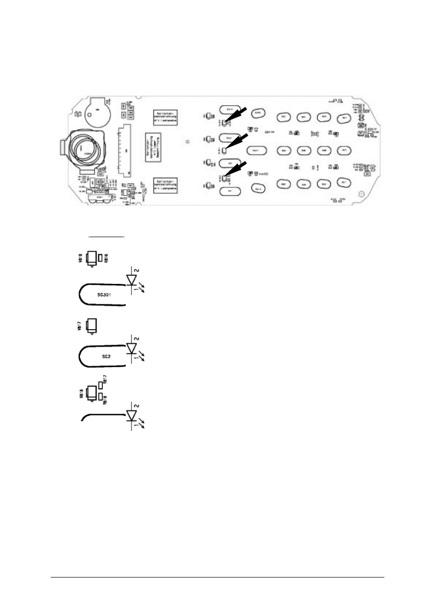
Figure 1: X35 board keyboard LED Side
Figure 2: X35 keyboard LED placement and polarity (top view)

V1.0
69
'LVSOD\ /('V
Affected Units
Type:
C/M/S 35
Affected IMEIs / Date Codes:
All / All
Affected SW-Versions:
All
Fault Code for LSO reporting:
3LED
Fault Description
Fault Symptoms for customers:
Display Illumination not working.
Fault Symptom on GSM-Tester:
This fault cannot be detected with a GSM-Tester
Priority:
........
Mandatory
_
........
Repair
........
Optional
........
Not Yet Defined

V1.0
70
Repair Documentation
Description of procedure:
D I AG N O S I S
Use the diode test function of a multimeter to check the status of the
diode.
The typical voltage drop on the diode is 1.7V when testing the diode
function with the multimeter.
Attention: There are two different types of display LEDs, one for
C/M35 and one for S35! Also they use different placement location,
see drawings 1 and 3.
R E P AI R B Y C O M P O N E N T C H AN G E
Use soldering iron to remove defective diode
Avoid excessive heat!
Watch surrounding components!
Resolder new diode afterwards.
R E P AI R B Y S W - B O O T I N G
Not possible!
T E S T
Retest handset after repair.
List of needed material
C O M P O N E N T S
Display LED S35
Part-Number: L36840-L2048-D670
Display LED C/M35
Part-Number: L36840-L2047-D670
J I G S A N D T O O L S
Hot Air Blower
Soldering Iron
V1.0
71
S P E C I AL T O O L S
None
W O R K I N G M AT E R I AL S
Desolder Wick / Braid
Solder
Drawings
Figure 1: C/M35 board display LED Side
Figure 2: C/M35 board display LED placement and polarity
V1.0
72
Figure 3: S35 board display LED side
Figure 4: S35 board display LED placement and polarity

V1.0
73
,QIUDUHG 'LRGHV
Affected Units
Type:
S 35
Affected IMEIs / Date Codes:
All / All
Affected SW-Versions:
All
Fault Code for LSO reporting:
3INF
Fault Description
Fault Symptoms for customers:
No infrared connection possible.
Fault Symptom on GSM-Tester:
This fault cannot be detected with a GSM-Tester.
Priority:
........
Mandatory
_
........
Repair
........
Optional
........
Not Yet Defined

V1.0
74
Repair Documentation
Description of procedure:
D I AG N O S I S
Visually check the status of the IrDa module. Watch for dry solder joints.
Use a reference infrared port (eg. from a notebook) to check the IrDa
function. If the notebook recognizes the S35, the infrared function is ok.
R E P AI R B Y C O M P O N E N T C H AN G E
Use hot air to remove defective infrared module.
Avoid excessive heat!
Watch surrounding components!!
Resolder new module afterwards
R E P AI R B Y S W - B O O T I N G
Not possible!
T E S T
Retest handset after repair.

75
List of needed material
C O M P O N E N T S
I N F R A R E D M O D U L E S 3 5
Part-Number: L36810-U6030-D670
J I G S AN D T O O L S
Soldering Iron
Hot Air Blower
S P E C I AL T O O L S
None
W O R K I N G M AT E R I AL S
Desolder Wick / Braid
Solder
76
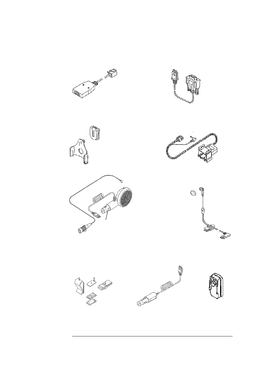
ANNEX C
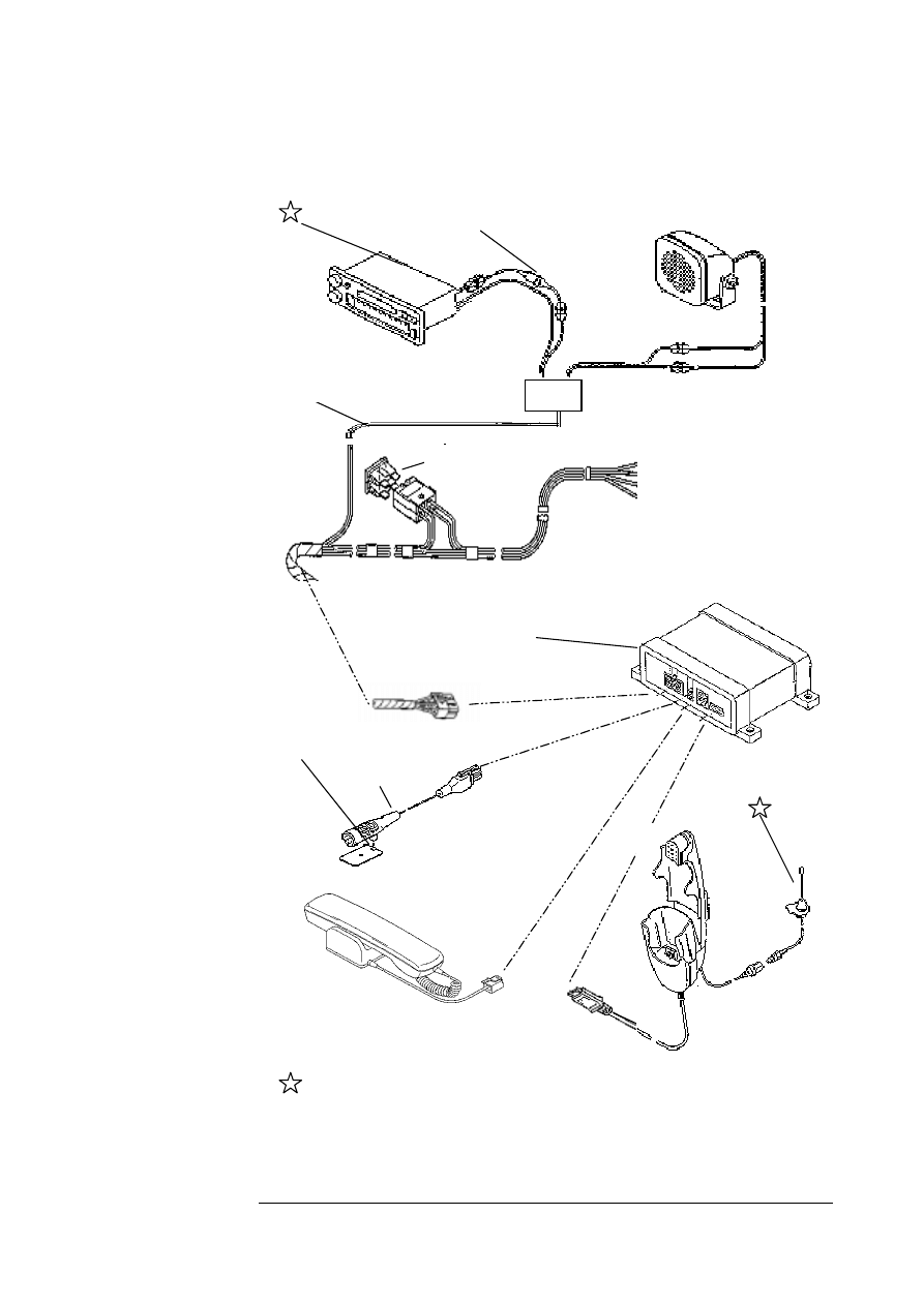
PC Adaptor Cable & Accessories C35
Belt Clip
L36880-N4001-A113
Car Kit Portable Handsfree Set
L36880-N3015-A117
Car Charger Cable 10,8-24V
L36880-N4001-A108
Adapter Cable E-Box-PC
L36880-N3101-A112
Adapter Cable PC-Mobilephone
L36880-N3101-A102
Headset
L36880-N4001-A123
Microphone Accessories Kit
L36158-A98-C6
Car Holder
L36158-A24-C25
Car Kit Portable Handsfree Microphone
L36254-Z6-C75
VDA Adaptercable
L36880-N4001-A121
12 V

77
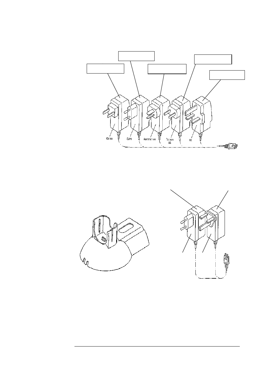
78
Power Plug for C35, M35 , S35
Desktop Charger
L36880-N4001-A102
Travel Charger 90-240 V
Travel Charger 90-240V
L36880-N4001-A103
L36880-N4001-A104
Eur
UK
Power Plug
L36280-Z4-C325
L36280-Z4-C321
L36280-Z4-C323
L36280-Z4-C324
L36280-Z4-
C322
79
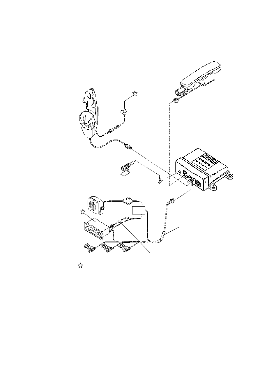
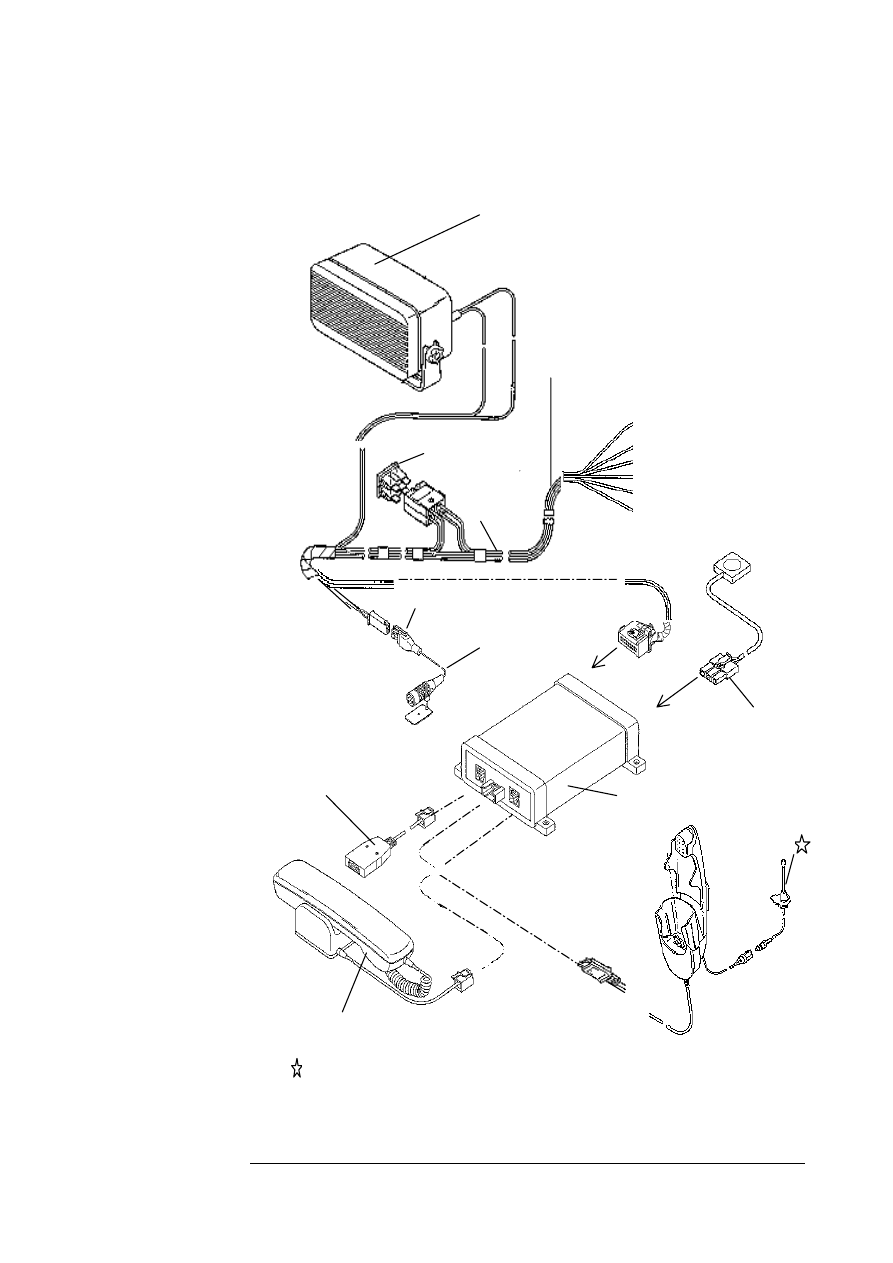
Car installation kit Ratio unit C35, M35 & S35
Handsfree Microphone
L36880-N4001-A116
1RW LQFOXGHG LQ RXU 6WDQGDUG 'HOOLYU\
O
Handset
L36880-N3015-A123
Cradle Comfort
L36158-A37-B1
Connection Box
Ratio
Con. Cable Battery
Comfort
L36146-A2053-D
Phone In Adapter
L36880-N3015-A137
80
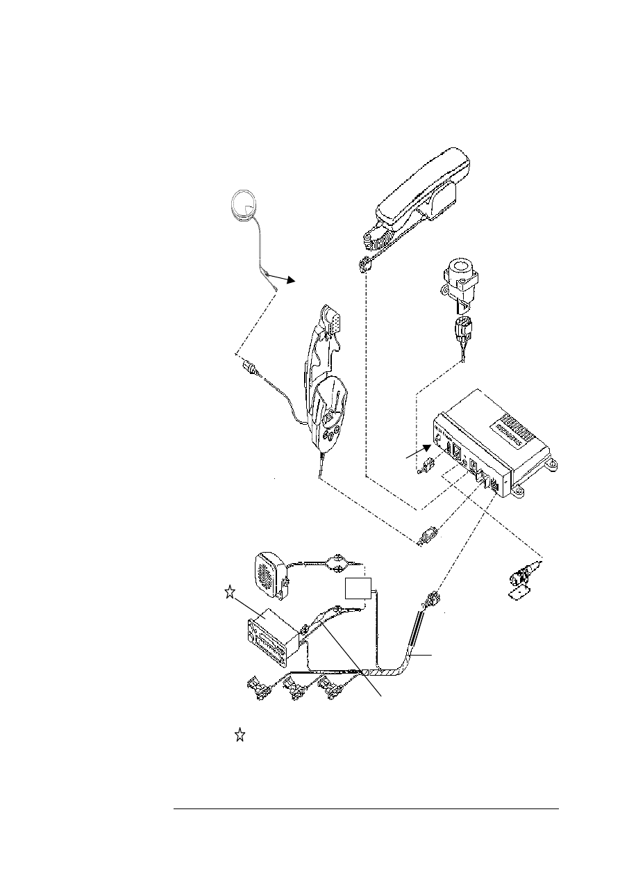
Car installation kit hands free unit C35, M35, S35
Radio Mute
black
Battery
red
Battery Ground
brown
Ignition
violet
Handsfree Microphone
L36254-Z6-C76
Connection Box
L36880-S2001-A100
3m
Handset
L36880-N3015-A123
Handsfree Loudspeaker
L36104-F3090-X902
Phone In Adaptor
L36880-N3015-A137
1RW LQFOXGHG LQ RXU 6WDQGDUG 'HOOLYU\ 3URJUDP
Fuses 3A
1,8m
Con. Cable Battery Comfort
L36146-A4013-D
OR
Cradle Comfort
L36158-A37-B1
81
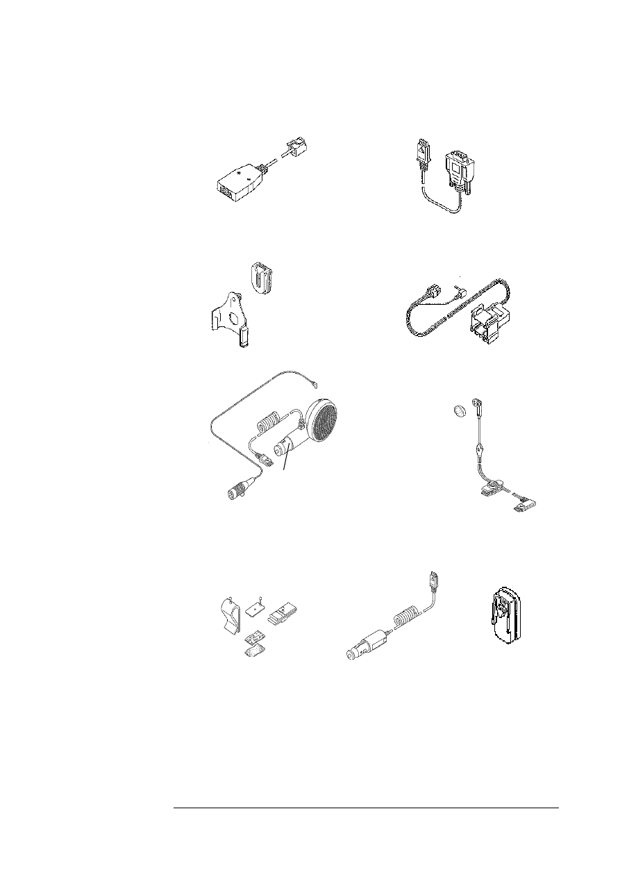
Carkit installation kit hand free unit Professional C35, M35, S35
Handsfree Loudspaker
L36104-F3090-X901
Fuses 3A
1,9m
Handset
L36880-N3015-
A123
3m
Radio Mute
black
Lights Dimmer
yellow
Automatic Antenna
white
Battery
red
Battery ground
brown
Ignition
violet
Adapter Cable E-Box-PC
L36880-N3101-A112
Con. Cable Battery
L36146-A1030-D
Push to talk
cable
L36146 A4012 D
Handfree Microphone
L36254-Z6-C63
Connection Box engl.
L36880-N3101-A110
Cradle Comfort
L36158-A37-B1
Not included in our Standard
82
Carkit installation Comfort GPS C35, M35, S35
Handsfree Microphone
L36880-N4001-A116
Antenna
Crash Sensor
L36880-N4001-A115
1RW LQFOXGHG LQ RXU 6WDQGDUG
Handset
L36880-N3015-
A123
O
Con. Cable Battery
L36146-A2053-D
Connection Pox GPS
L36880-S4001-A4
Car Cradle Telematic
L36158-A37-B6
Con. Pox
Combi Antenna GPS
L36851-Z1901-A46
Handsfree Loudspeaker
L36104-F3090-X902
Phone In Adapter
L36880-N3015-A137
83
PC Adaptar Cable & Accessory C35, M35, S35
Belt Clip
L36880-N4001-A113
Car Kit Portable Handsfree Set
L36880-N3015-A117
Car Charger cable 10, 8 – 24V
L36880-N4001-A108
Adaptor Cable E-Box -PC
L36880-N3101-A112
Adapter Cable PC-Mobilephone
L36880-N3101-A102
Headset
L36880-N4001-A123
Microphone Accessories Kit
L36158-A98-C6
Car Holder
L36158-A24-C25
Car Kit Portable Handsfree Microphone
L36254-Z6-C75
VDA Adaptercable
L36880-N4001-A121
12 V

84
References:
1. Mouly M. & Pautet M-B. (1992)
The GSM System for Mobile Communications, A
comprehensive overview of the European Digital Cellular Systems France:
Published by authors.
2. Scourias,
J
Overview of the Global System for Mobile Communications University
of Waterloo: Published by author.
3. - (1998)
GSM Introduction Published by Wavetek Wireless Communication
Division.
4. Barnes, N
SIM Application Toolkit, Article by author on ETSI Website.
5. Mehrotra A, (1994),
Cellular Radio Analog and Digital System, Artech House Inc,
USA.
6. IrDA(Infrared
Data
Association),
Serial Infrared Physical Layer Link Specification,
Version 1.1, October 15, 1995.
Disclaimer: This content is subjected to change without notice.
Copyright
2000 Siemens Advanced Engineering Pte Ltd
ICP CD Asia Service Center,
164, Kallang Way, #04-22, Kolam Ayer Industrial Estate, Singapore 349248
Author: Tan Guan San.
Phone +65-8454822 • Fax +65-8426641
First Print: April, 00
Revised Print:
The reproduction and transmission of this document to unauthorized parties is not permitted
without written authority. Offender will be liable for damages.
Wyszukiwarka
Podobne podstrony:
sm S25 lvl V10
Program studiów SM IE
2015 06 podst SM
EMP7700 ASM E B SM
Flaminio Costa VS ENEL, stosunki międzynarodowe, sm iii rok
SM ściąga, Politologia WSNHiD, Licencjat, V SEMESTR, Stosunki międzynarodowe
SM ćwiczenia ściaga II
M5 Modelowanie i symulacja silnika wrzecionowego SM
Program wymagania z audycji muzycznych kl IV do VI SM I stopień
347 671 1 SM
Leczenie przyczynowe sm
5163 15354 1 SM
50 54 1 SM
2. Zasada praw. zaufania, Notatki SM, Notatki SM, SMobsługa ruchu semestr V, postepowanie celna
Formizm sm, Dziennikarstwo
Ser Gouda, 1---Eksporty-all, 1---Eksporty---, 4---towary-PL+world, PL-towary-all, 3---milk-products,
ISCW V10 Vol2
więcej podobnych podstron