
400LF–01
–
AUTOMATIC TRANSMISSION / TRANS
AUTOMATIC TRANSAXLE ASSY (ATM)
40–1
1351
Author:
Date:
2004 COROLLA (RM1037U)
AUTOMATIC TRANSAXLE ASSY (ATM)
PRECAUTION
1.
The automatic transaxle is composed of highly precision–finished parts, necessitating careful
inspection before reassembly because even a small nick could cause fluid leakage or affect
the performance. The instructions here are organized so that you work on only one component
group at a time. This will help avoid confusion from similar–looking parts of different sub–as-
semblies being on your workbench at the same time. The component groups are inspected and
repaired from the converter housing side. As much as possible, complete the inspection, repair
and reassembly before proceeding to the next component group. If a defect is found in a certain
component group during reassembly, inspect and repair this group immediately. If a compo-
nent group cannot be assembled because parts are being ordered, be sure to keep all parts of
the group in a separate container while proceeding with disassembly, inspection, repair and
reassembly of other component groups.
Recommended ATF: T–IV
2.
All disassembled parts should be washed clean and any fluid passages and holes should be
blown through with compressed air.
3.
Dry all parts with compressed air–never use shop rags.
4.
When using compressed air, always aim away from yourself to prevent accidentally spraying
ATF or kerosene on your face.
5.
The recommended automatic transaxle fluid or kerosene should be used for cleaning.
6.
After cleaning, the parts should be arranged in the correct order for efficient inspection, repairs,
and reassembly.
7.
When disassembling a valve body, be sure to match each valve together with the correspond-
ing spring.
8.
New discs for the brakes and clutches that are to be used for replacement must be soaked in
ATF for at least 15 minutes before reassembly.
9.
All oil seal rings, clutch discs, clutch plates, rotating parts, and sliding surfaces should be
coated with ATF prior to reassembly.
10.
All gaskets and rubber O–rings should be replaced.
11.
Do not apply adhesive cements to gaskets and similar parts.
12.
Make sure that the ends of a snap ring are not aligned with one of the cutouts and are installed
in the groove correctly.
13.
If a worn bushing is to be replaced, the sub–assembly containing the bushing must also be re-
placed.
14.
Check thrust bearings and races for wear or damage. Replace if necessary.
15.
Use petroleum jelly to keep parts in place.
16.
When working with FIPG material, you must observe the following.
Using a razor blade and a gasket scraper, remove all the old packing (FIPG) material from the
gasket surface.
Thoroughly clean all components to remove all the loose material.
Clean both sealing surfaces with a non–residue solvent.
Parts must be reassembled within 10 minutes of application. Otherwise, the packing (FIPG) ma-
terial must be removed and reapplied.
400LG–01
D25120
Add if hot
OK if hot
40–2
–
AUTOMATIC TRANSMISSION / TRANS
AUTOMATIC TRANSAXLE FLUID (ATM)
1352
Author:
Date:
2004 COROLLA (RM1037U)
AUTOMATIC TRANSAXLE FLUID (ATM)
ON–VEHICLE INSPECTION
1.
CHECK THE FLUID LEVEL
HINT:
Drive the vehicle so that the engine and transaxle are at normal
operating temperature.
Fluid temperature: 70 – 80
°
C (158 – 176
°
F)
(a)
Park the vehicle on a level surface and set the parking
brake.
(b)
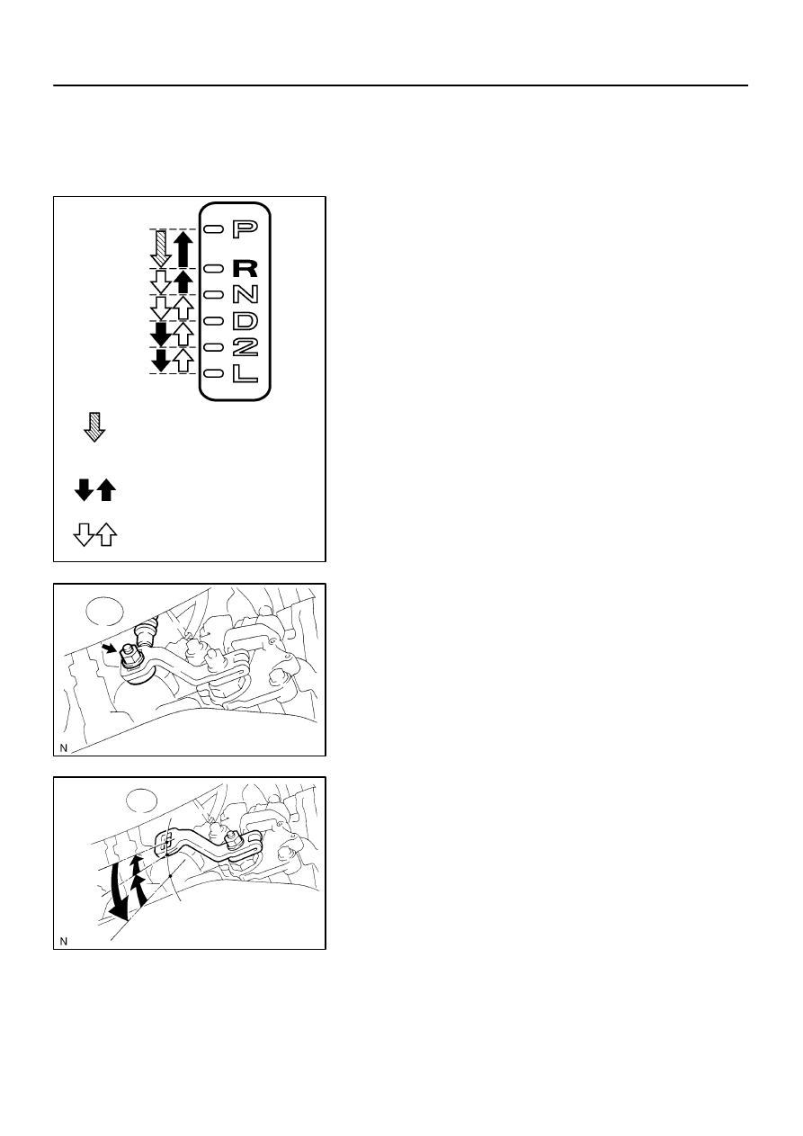
With the engine idling and the brake pedal depressed,
shift the shift lever into all ranges from P to L position and
return to P position.
(c)
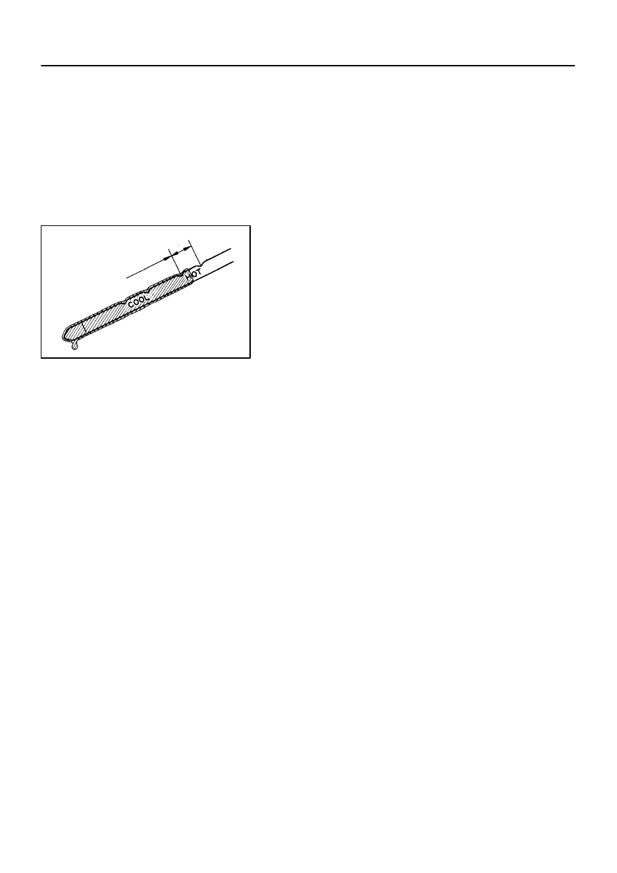
Pull out the dipstick and wipe it clean.
(d)
Push it back fully into the pipe.
(e)
Pull it out and check that the fluid level is in the HOT posi-
tion.
If there are leaks, it is necessary to repair or replace O–rings,
FIPGs, oil seals, plugs or other parts.
400LH–01
C80159
C96147
D25124
D09957
–
AUTOMATIC TRANSMISSION / TRANS
PARK/NEUTRAL POSITION SWITCH ASSY (ATM)
40–3
1353
Author:
Date:
2004 COROLLA (RM1037U)
PARK/NEUTRAL POSITION SWITCH ASSY (ATM)
REPLACEMENT
1.
REMOVE BATTERY
2.
REMOVE BATTERY CARRIER
(a)
Remove the 4 bolts and battery carrier.
3.
DISCONNECT FLOOR SHIFT CABLE TRANSMISSION
CONTROL SHIFT
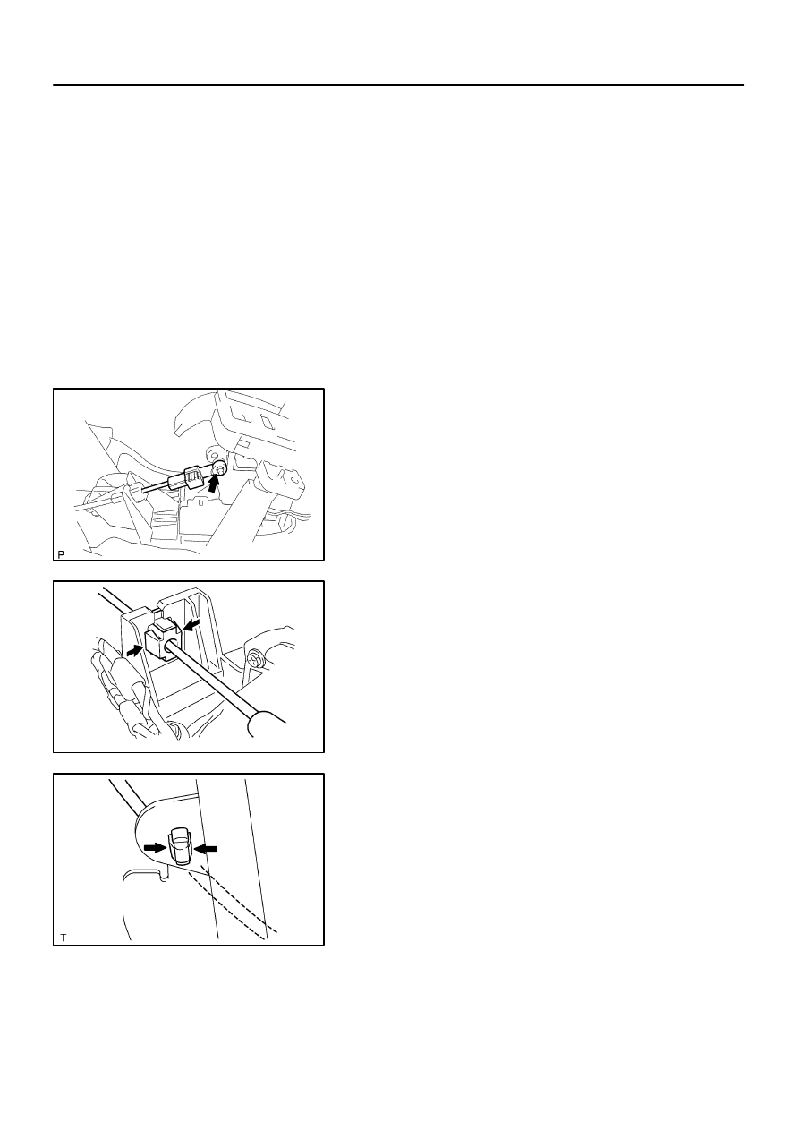
(a)
Remove the nut from the control shaft lever.
(b)
Disconnect the control cable from the control shaft lever.
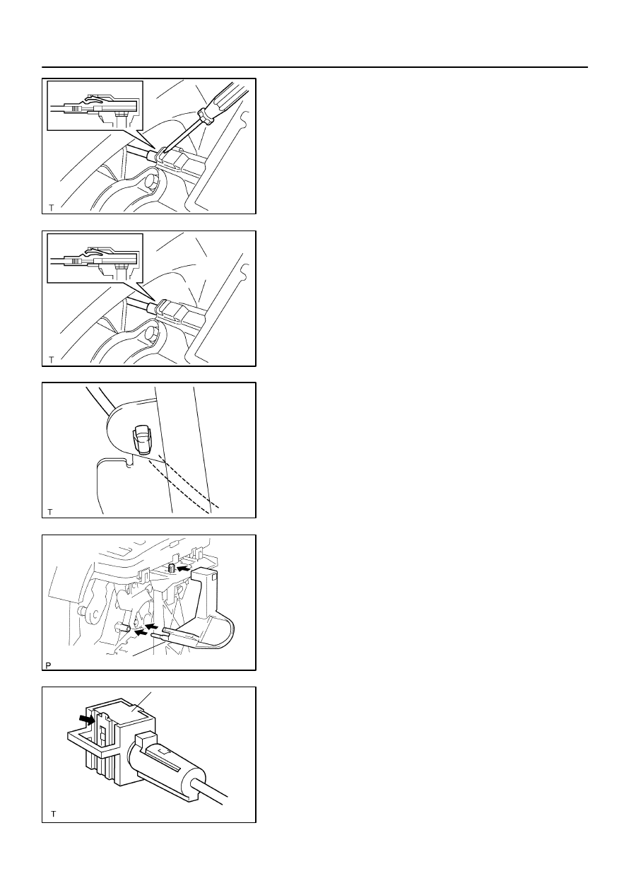
(c)
Remove the clip and disconnect the control cable from
the control cable bracket.
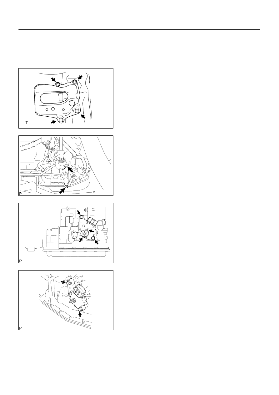
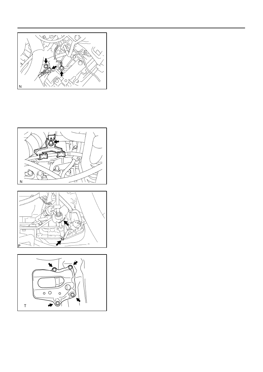
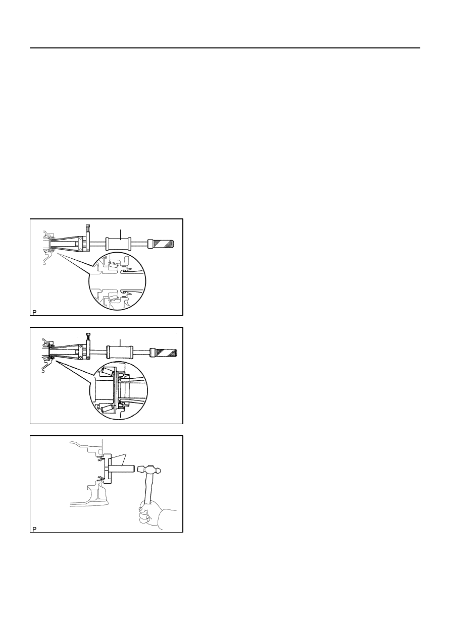
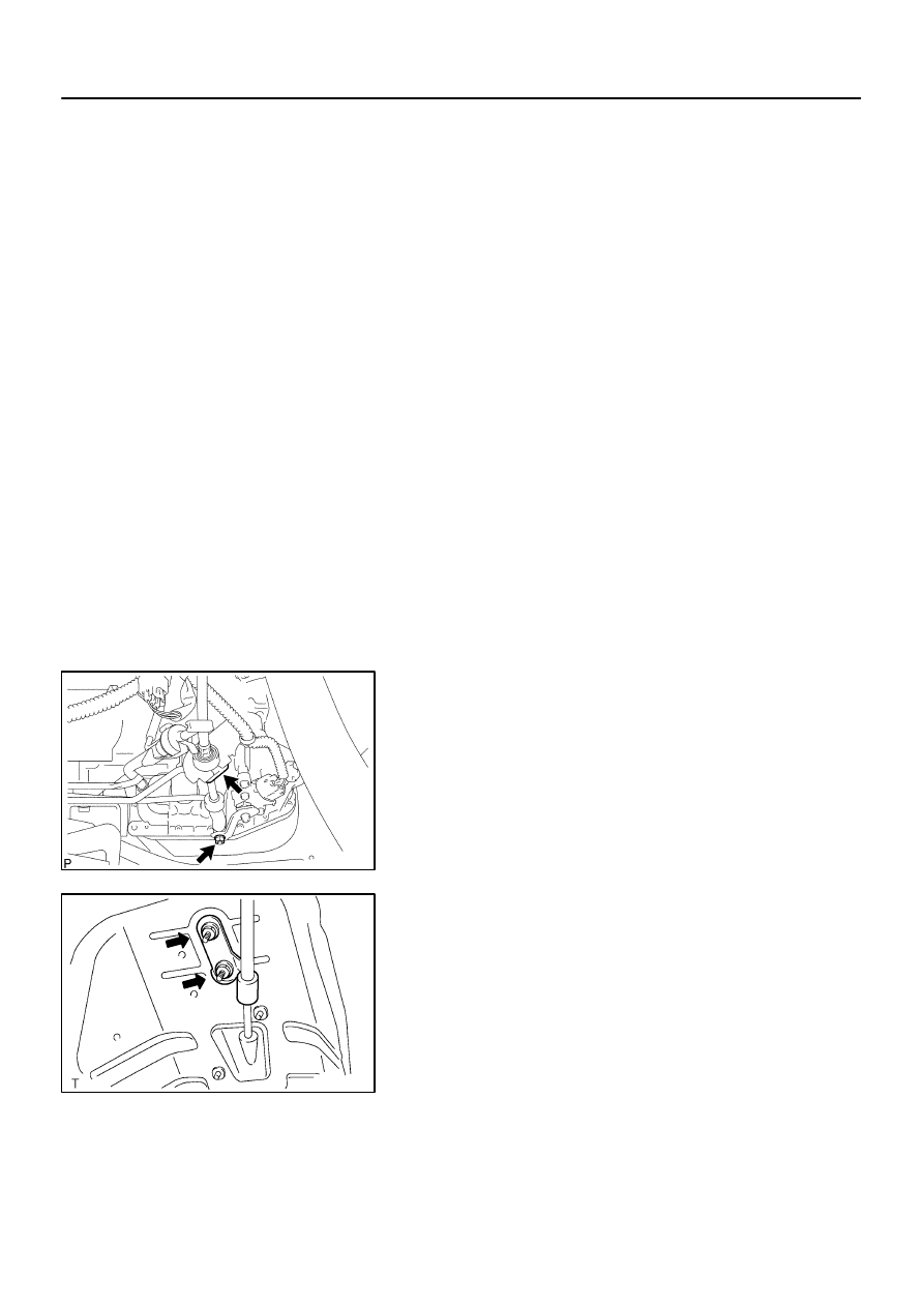
4.
REMOVE PARK/NEUTRAL POSITION SWITCH ASSY
(a)
Disconnect the park/neutral position switch connector.
(b)
Remove the nut, washer and control shaft lever.
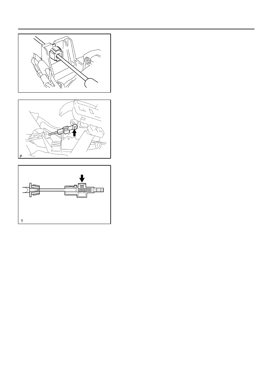
(c)
Pry out the lock plate and remove the manual valve shaft
nut.
(d)
Remove the 2 bolts and pull out the park/neutral position
switch.
5.
INSTALL PARK/NEUTRAL POSITION SWITCH ASSY
(a)
Install the park/neutral position switch to the manual valve
shaft.
(b)
Temporarily install the 2 bolts.
(c)
Place a new lock plate and tighten the nut.
Torque: 5.5 N
⋅
m (56 kgf
⋅
cm, 49 in.
⋅
lbf)
(d)
Temporarily install the control shaft lever.
D25126
D08584
Groove
Neutral
Basic Line
D08585
D25125
C96147
40–4
–
AUTOMATIC TRANSMISSION / TRANS
PARK/NEUTRAL POSITION SWITCH ASSY (ATM)
1354
Author:
Date:
2004 COROLLA (RM1037U)
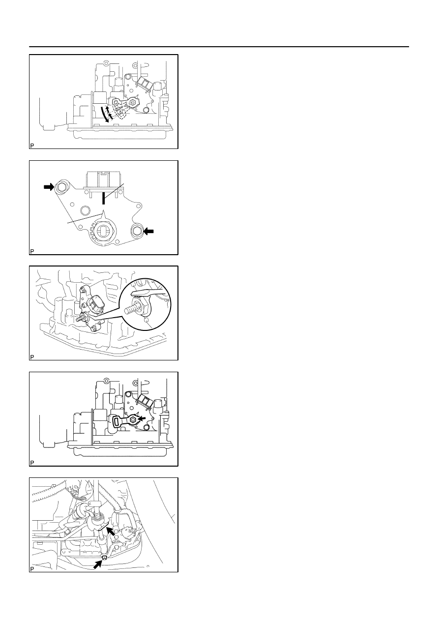
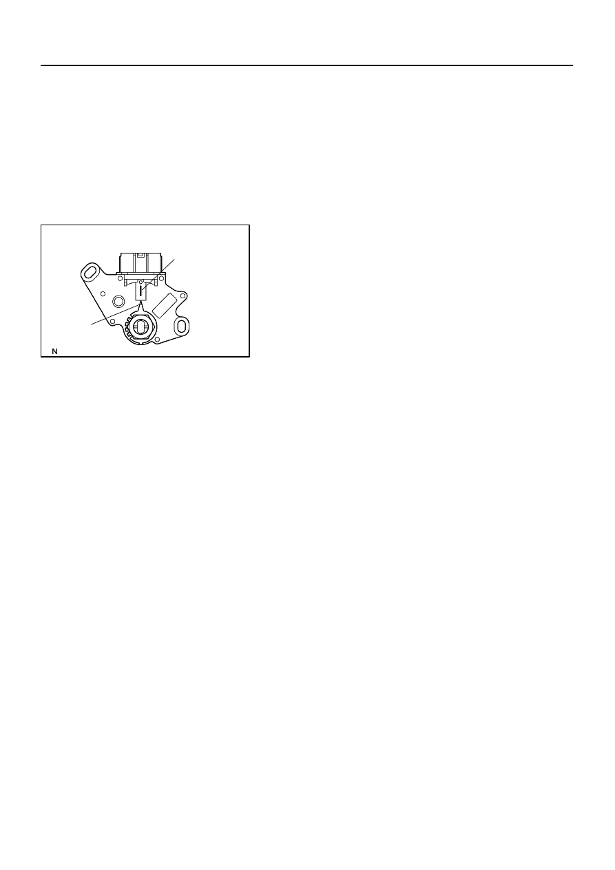
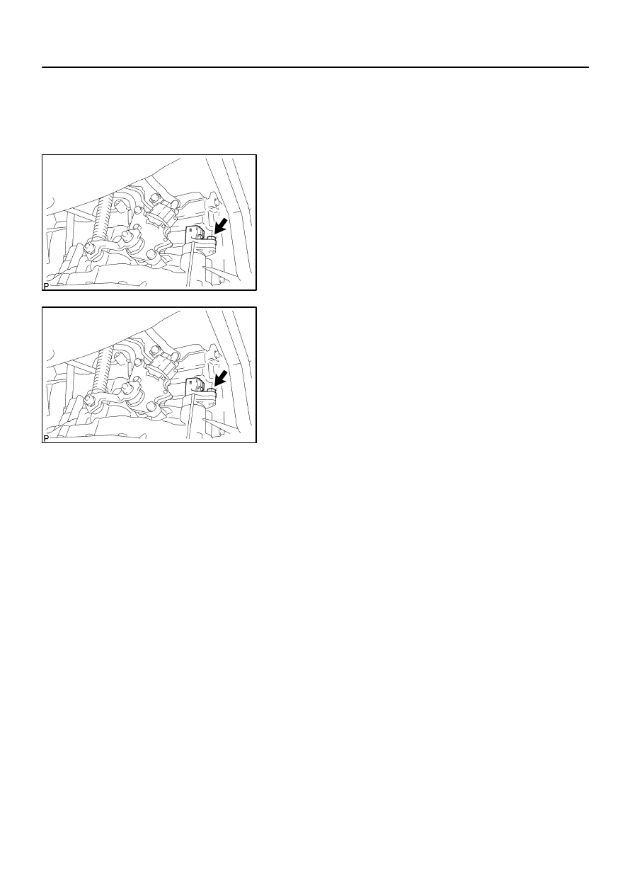
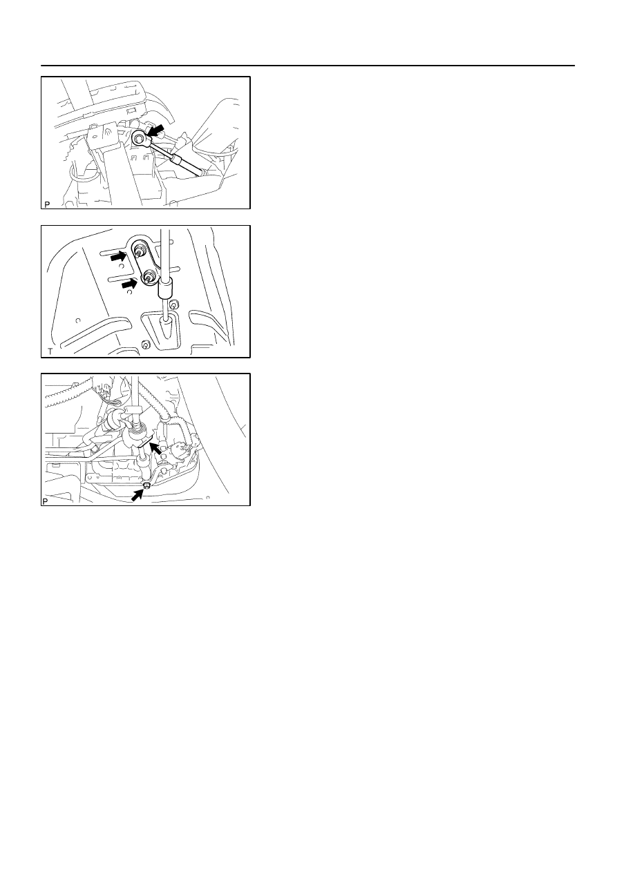
(e)
Turn the lever counterclockwise until it stops, then turn it
clockwise 2 notches.
(f)
Remove the control shaft lever.
(g)
Align the groove with neutral basic line.
(h)
Hold the switch in position and tighten the 2 bolts.
Torque: 5.5 N
⋅
m (56 kgf
⋅
cm, 49 in.
⋅
lbf)
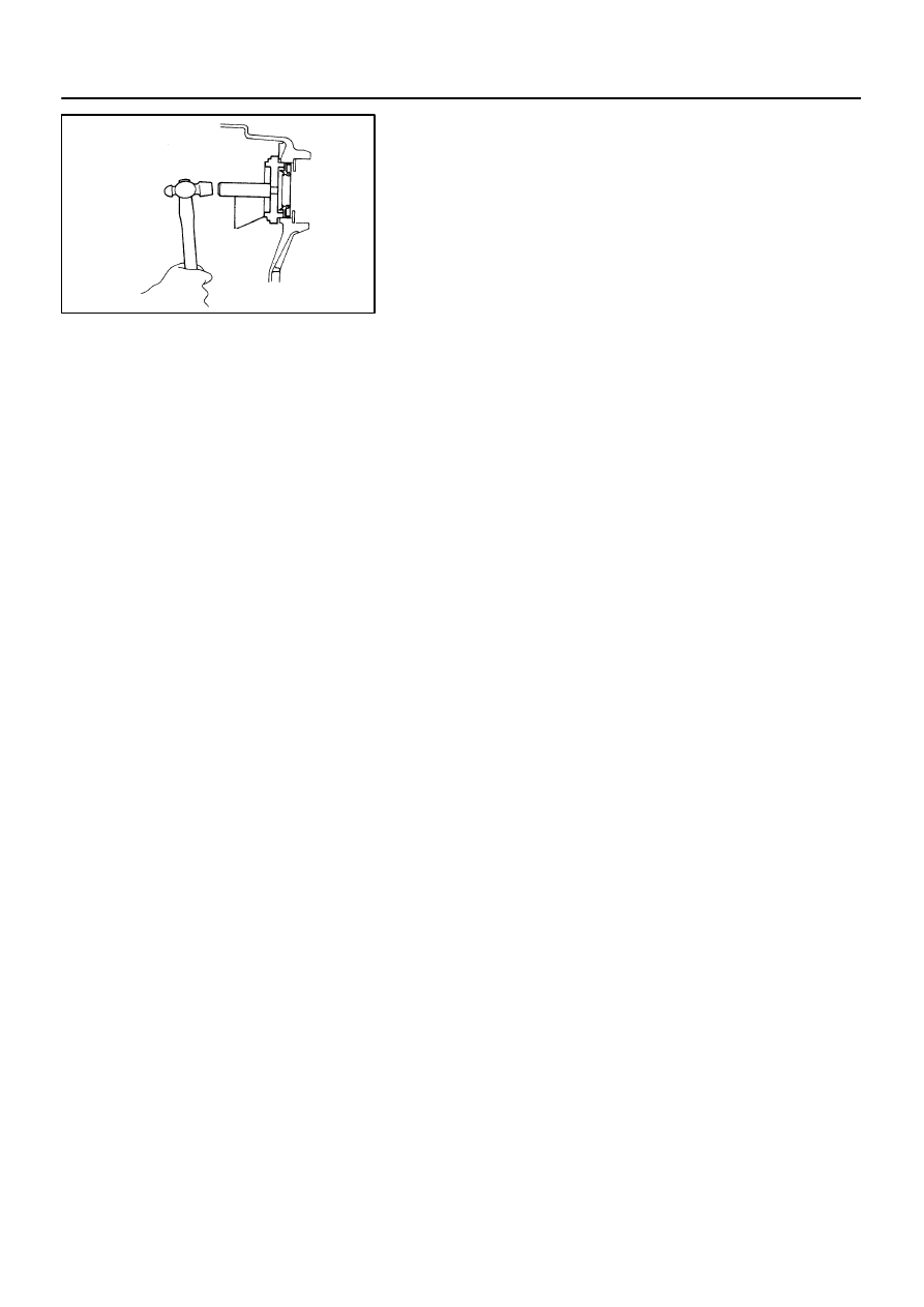
(i)
Using a screwdriver, stake the nut with the lock plate.
(j)
Install the control shaft lever, washer and nut.
Torque: 12.5 N
⋅
m (127 kgf
⋅
cm, 9 ft
⋅
lbf)
(k)
Connect the park/neutral position switch connector.
6.
INSTALL FLOOR SHIFT CABLE TRANSMISSION
CONTROL SHIFT
(a)
Temporarily install the control cable to the control shaft le-
ver with nut.
(b)
Install the control cable and clip to the bracket.
C80159
–
AUTOMATIC TRANSMISSION / TRANS
PARK/NEUTRAL POSITION SWITCH ASSY (ATM)
40–5
1355
Author:
Date:
2004 COROLLA (RM1037U)
7.
INSTALL BATTERY CARRIER
(a)
Install the battery carrier and 4 bolts.
Torque: 13 N
⋅
m (132 kgf
⋅
cm, 10 ft
⋅
lbf)
8.
ADJUST SHIFT LEVER POSITION (See page
40–44
)
9.
INSPECT SHIFT LEVER POSITION (See page
40–44
)
10.
INSPECT PARK/NEUTRAL POSITION SWITCH ASSY (See page
40–6
)
400LI–01
D25514
Neutral
Basic Line
Groove
40–6
–
AUTOMATIC TRANSMISSION / TRANS
PARK/NEUTRAL POSITION SWITCH ASSY (ATM)
1356
Author:
Date:
2004 COROLLA (RM1037U)
ADJUSTMENT
1.
INSPECT PARK/NEUTRAL POSITION SWITCH ASSY
(a)
Apply the parking brake and turn the ignition switch ON.
(b)
Depress the brake pedal and check that the engine starts only when the shift lever is set in N or P posi-
tion and it does not start in the other position.
(c)
Check that the back–up light comes on and the reverse warning buzzer sounds only when the shift
lever is set in R position and these do not function in the other positions.
If a failure is found, check the park/ neutral position switch for continuity.
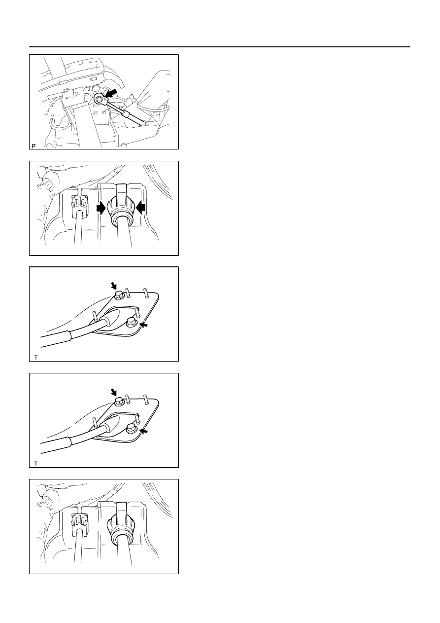
2.
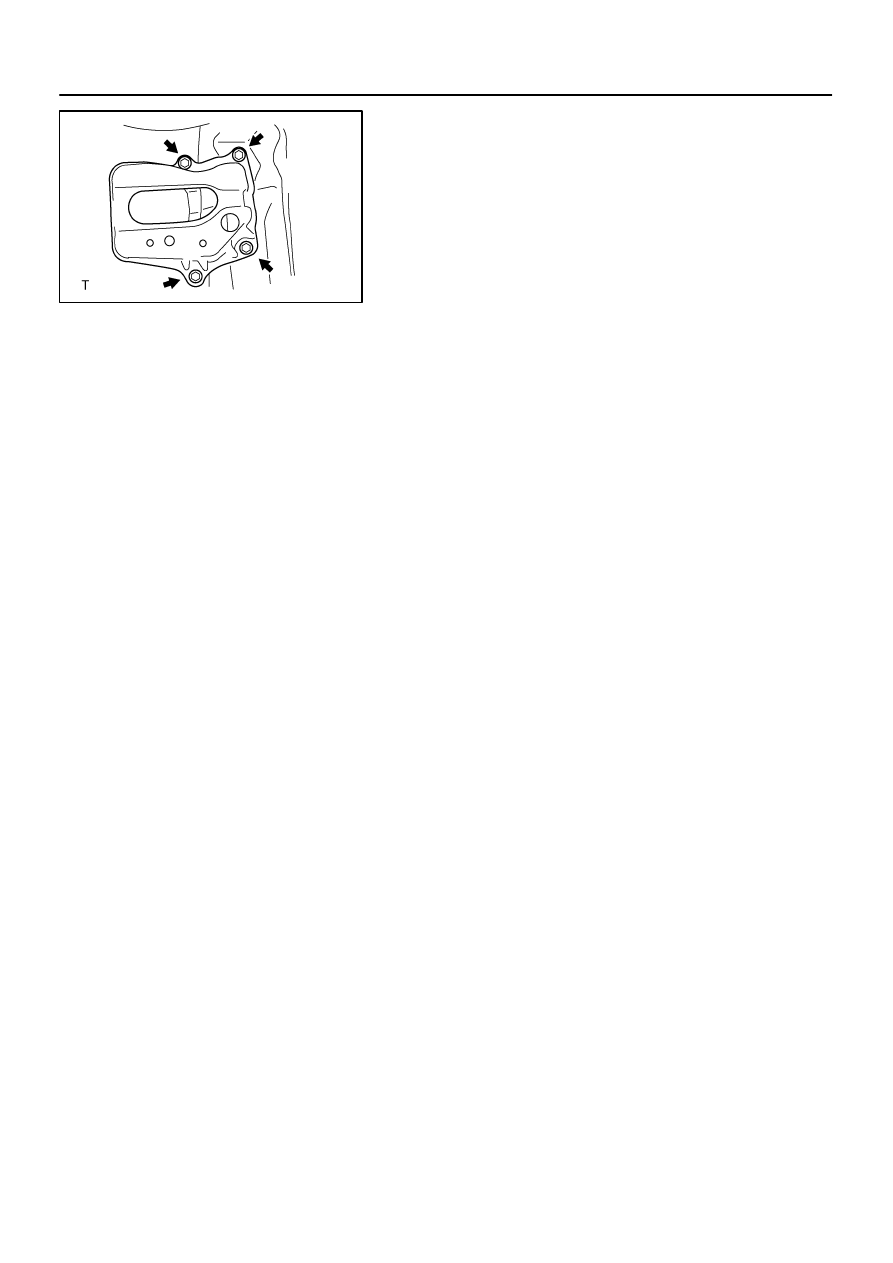
ADJUST PARK/NEUTRAL POSITION SWITCH ASSY
(a)
Loosen the 2 bolts of park/ neutral position switch and set
the shift lever to the N position.
(b)
Align the groove and neutral basic line.
(c)
Hold the switch in position and tighten the 2 bolts.
Torque: 5.5 N
⋅
m (56 kgf
⋅
cm, 49 in.
⋅
lbf)
(d)
After adjustment, perform the inspection described in
step 1.
400LJ–01
C95348
N
⋅
m (kgf
⋅
cm, ft
⋅
lbf)
: Specified torque
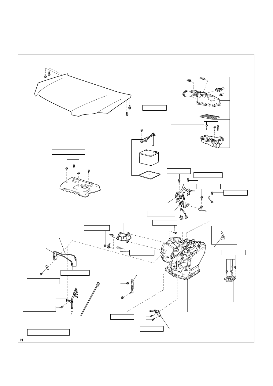
Non–reusable part
ATF Level Gauge
O–ring
Transmission Oil Filler
Tube Sub–assy
Transmission Control Cable
Bracket No.1
Automatic Transaxle Assy
Battery Carrier
Floor Shift Cable Transmission
Control Shift
Clip
Oil Cooler Inlet Tube No.1
Oil Cooler Outlet
Tube No.1
Starter Assy
12.75 (130, 9)
13 (132, 10)
39 (400, 29)
25.5 (260, 19)
13 (132, 10)
13 (132, 10)
39 (400, 29)
5.5 (56, 49 in.
⋅
lbf)
34.5 (350, 25)
5.5 (56, 49 in.
⋅
lbf)
12 (122, 9)
12 (122, 9)
Hood Sub–assy
12 (122, 9)
10 (102, 7)
13 (132, 10)
Air Cleaner Assy
7.0 (71, 62 in.
⋅
lbf)
Battery
Cylinder Head
Cover No.2
7.0 (71, 62 in.
⋅
lbf)
Control Cable Support
w/o ABS:
Speedometer sensor
connector
–
AUTOMATIC TRANSMISSION / TRANS
AUTOMATIC TRANSAXLE ASSY (ATM)
40–7
1357
Author:
Date:
2004 COROLLA (RM1037U)
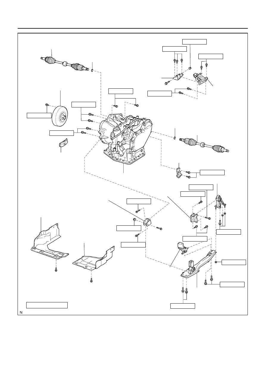
AUTOMATIC TRANSAXLE ASSY (ATM)
COMPONENTS
C95349
N
⋅
m (kgf
⋅
cm, ft
⋅
lbf)
: Specified torque
Non–reusable part
Engine Under Cover RH
Engine Under Cover LH
Engine Mounting Member
Sub–assy Center
Engine Mounting
Bracket RR
Engine Mounting Insulator RR
52 (530, 38)
64 (652, 47)
52 (530, 38)
52 (530, 38)
39 (398, 29)
Automatic Transaxle Assy
Flywheel Housing Under Cover
Transmission Case Protector
Front Drive Shaft Assy LH
Snap Ring
Engine Mounting
Bracket LH
Engine Mounting
Insulator LH
Snap Ring
Front Drive Shaft Assy RH
Torque Converter Clutch Assy
x 6
64 (650, 47)
46 (470, 34)
23 (235, 17)
52 (530, 38)
52 (530, 38)
80 (815, 59)
52 (530, 38)
18 (182, 14)
28 (285, 20)
64 (652, 47)
87 (887, 64)
Front Suspension Member Dynamic
Damper
Engine Mounting Bracket FR
64 (652, 47)
64 (652, 47)
52 (530, 38)
40–8
–
AUTOMATIC TRANSMISSION / TRANS
AUTOMATIC TRANSAXLE ASSY (ATM)
1358
Author:
Date:
2004 COROLLA (RM1037U)
400LK–02
C80159
C96147
C95750
–
AUTOMATIC TRANSMISSION / TRANS
AUTOMATIC TRANSAXLE ASSY (ATM)
40–9
1359
Author:
Date:
2004 COROLLA (RM1037U)
REPLACEMENT
1.
REMOVE HOOD SUB–ASSY
2.
REMOVE CYLINDER HEAD COVER NO.2
3.
REMOVE BATTERY
4.
REMOVE BATTERY CARRIER
(a)
Remove the 4 bolts and battery carrier.
5.
REMOVE AIR CLEANER ASSEMBLY WITH HOSE
6.
REMOVE FLOOR SHIFT CABLE TRANSMISSION
CONTROL SHIFT
(a)
Remove the nut from the control shaft lever.
(b)
Disconnect the control cable from the control shaft lever.
(c)
Remove the clip and disconnect the control cable from
the control cable bracket.
7.
REMOVE TRANSMISSION CONTROL CABLE
SUPPORT
(a)
Disconnect the wire harness clamp and control cable
from the control cable support.
(b)
Remove the bolt and control cable support.
8.
REMOVE TRANSMISSION CONTROL CABLE BRACKET NO.1
(a)
Remove the 2 bolts and control cable bracket.
C93666
C93643
D09961
C93646
SST
40–10
–
AUTOMATIC TRANSMISSION / TRANS
AUTOMATIC TRANSAXLE ASSY (ATM)
1360
Author:
Date:
2004 COROLLA (RM1037U)
9.
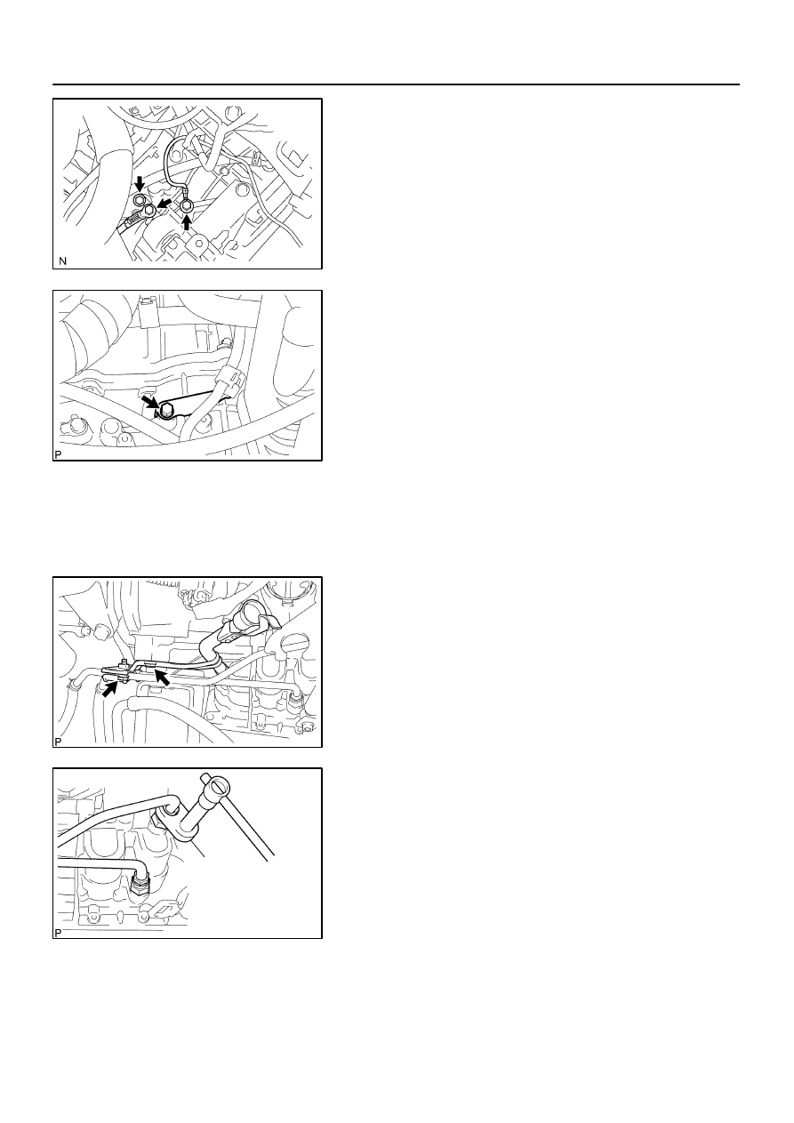
DISCONNECT WIRE HARNESS
(a)
Remove the 2 bolts and disconnect the 2 wire harnesses.
(b)
Remove the bolt and disconnect the wire harness clamp
bracket.
(c)
Remove the bolt and disconnect the wire harness clamp
bracket.
10.
DISCONNECT CONNECTOR
(a)
Disconnect the transmission wire connector.
(b)
Disconnect the park/neutral position switch connector.
(c)
w/o ABS:
Disconnect the speedometer sensor connector.
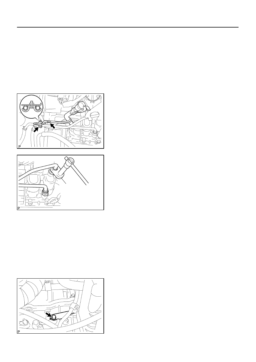
11.
REMOVE TRANSMISSION OIL FILLER TUBE
SUB–ASSY
(a)
Remove the ATF lever gauge.
(b)
Remove the 2 bolts, oil cooler tube clamp and oil filler
tube.
(c)
Remove the O–ring from the oil filler tube.
12.
DISCONNECT OIL COOLER INLET TUBE NO.1
(a)
Using SST, disconnect the oil cooler inlet tube No. 1.
SST
09023–12700
13.
DISCONNECT OIL COOLER OUTLET TUBE NO.1
(a)
Using SST, disconnect the oil cooler outlet tube No. 1.
SST
09023–12700
D25372
Front
Rear
No. 1
Engine Hanger
No. 2
Engine Hanger
D09964
–
AUTOMATIC TRANSMISSION / TRANS
AUTOMATIC TRANSAXLE ASSY (ATM)
40–11
1361
Author:
Date:
2004 COROLLA (RM1037U)
14.
DISCONNECT OXYGEN SENSOR CONNECTOR
(a)
Remove the foot rest.
(b)
Pull up the floor carpet.
(c)
Disconnect the oxygen sensor connector.
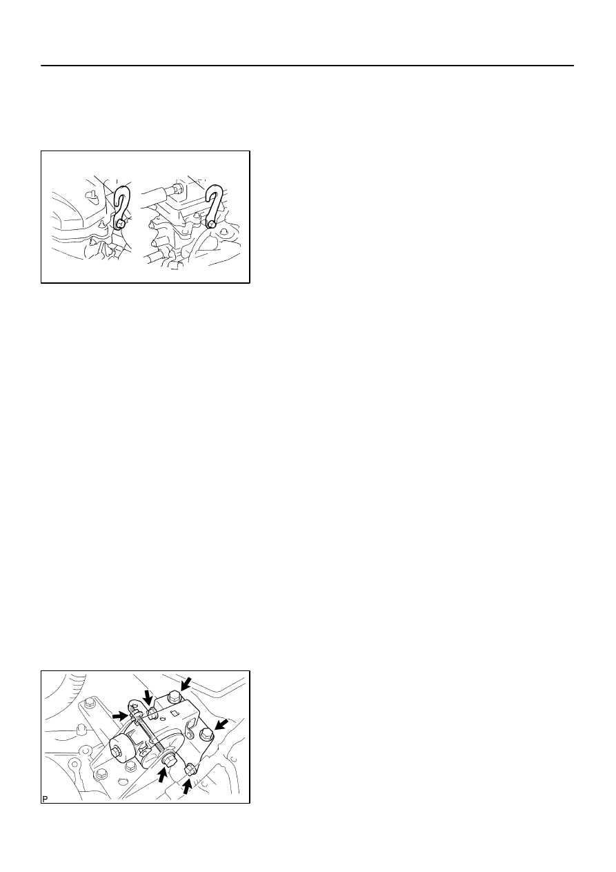
15.
SUSPEND ENGINE ASSY
(a)
Disconnect the 2 PCV hoses.
(b)
Install the No.1 and No.2 engine hangers in the correct
direction.
Parts No.:
No.1 engine hanger: 12281–22021
No.2 engine hanger: 12281–15040
Bolt: 91512–B1016
Torque: 38 N
⋅
m (387 kgf
⋅
cm, 28 ft
⋅
lbf)
(c)
Attach the engine chain hoist to the engine hangers.
CAUTION:
Do not attempt to hang the engine by hooking the chain to
any other parts.
16.
REMOVE FRONT WHEELS
17.
REMOVE ENGINE UNDER COVER RH
18.
REMOVE ENGINE UNDER COVER LH
19.
DRAIN AUTOMATIC TRANSAXLE FLUID
(a)
Remove the drain plug and gasket, and drain ATF.
(b)
Install a new gasket and drain plug.
Torque: 17.5 N
⋅
m (178 kgf
⋅
cm, 13 ft
⋅
lbf)
20.
REMOVE EXHAUST PIPE ASSY FRONT (See page
15–2
)
21.
REMOVE FRONT DRIVE SHAFT ASSY RH (See page
30–6
)
SST
09520–01010, 09520–24010 (09520–32040)
22.
REMOVE FRONT DRIVE SHAFT ASSY LH (See page
30–6
)
SST
09520–01010, 09520–24010 (09520–32040)
23.
REMOVE AUTOMATIC TRANSMISSION CASE PROTECTOR
(a)
Remove the 2 bolts and case protector.
24.
REMOVE STARTER ASSY
(a)
Remove the nut and disconnect the starter wire.
(b)
Disconnect the connector.
(c)
Remove the 2 bolts and starter.
25.
SUPPORT AUTOMATIC TRANSAXLE ASSY
(a)
Support the automatic transaxle with a transmission jack.
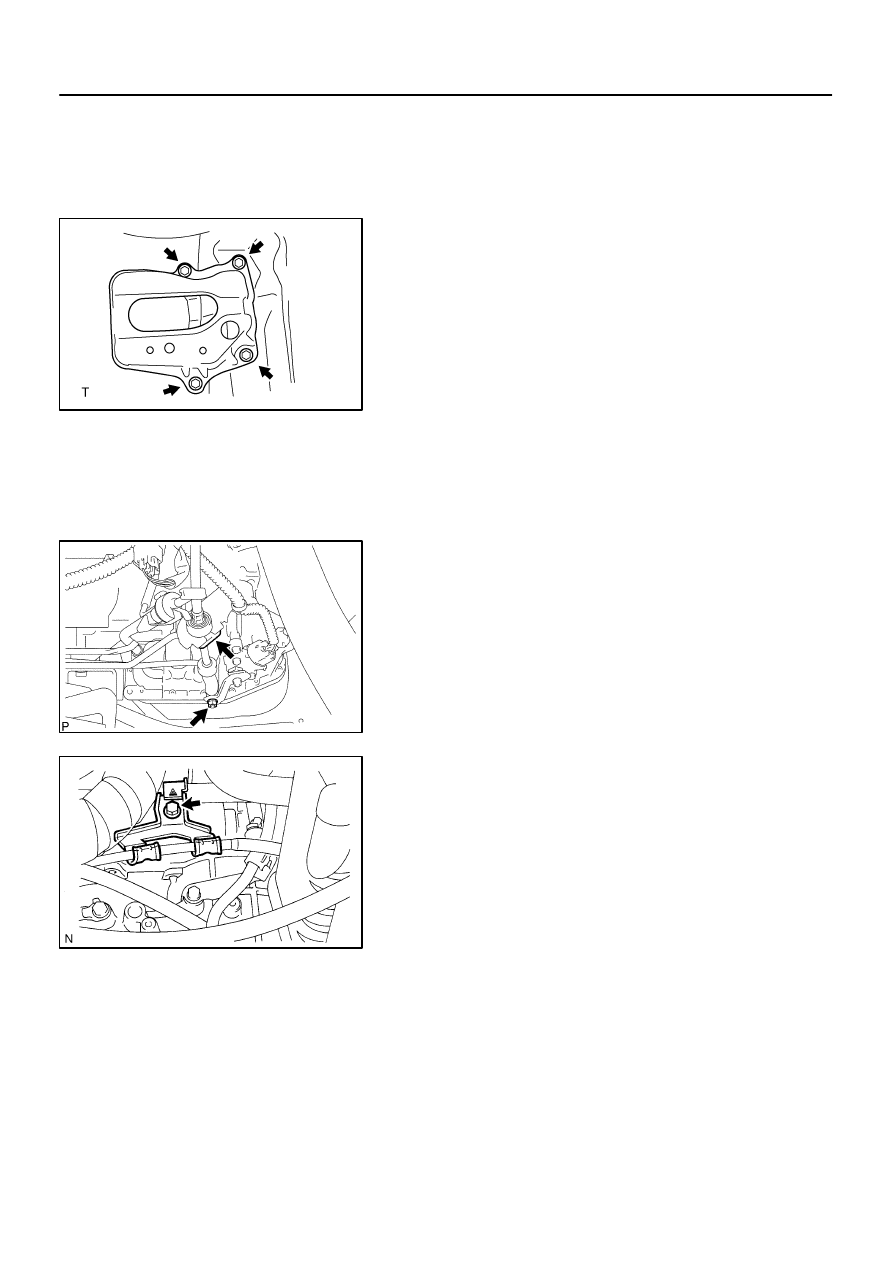
26.
REMOVE TRANSVERSE ENGINE ENGINE
MOUNTING INSULATOR
(a)
Remove the 5 bolts, nut and engine mounting insulator
LH.
D09965
C80192
C80167
C80166
C95354
40–12
–
AUTOMATIC TRANSMISSION / TRANS
AUTOMATIC TRANSAXLE ASSY (ATM)
1362
Author:
Date:
2004 COROLLA (RM1037U)
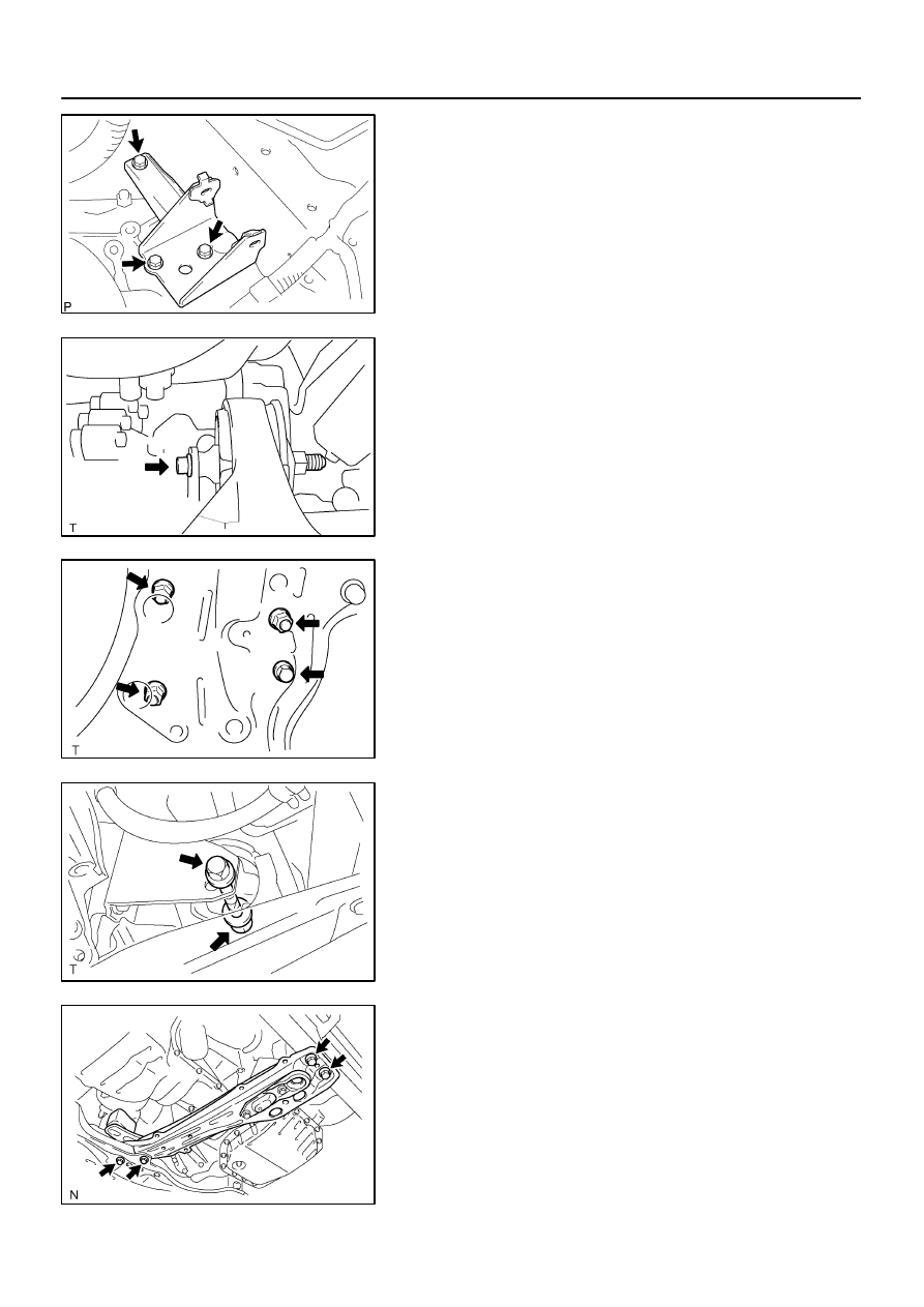
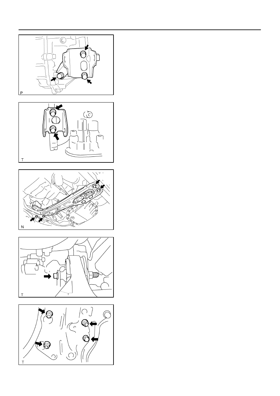
27.
REMOVE TRANSVERSE ENGINE ENGINE
MOUNTING BRACKET
(a)
Remove the 3 bolts and engine mounting bracket LH.
28.
REMOVE TRANSVERSE ENGINE ENGINE
MOUNTING INSULATOR
(a)
Remove the bolt from the engine mounting bracket RR.
(b)
Remove the 3 nuts, bolt and engine mounting insulator
RR from the suspension member.
29.
REMOVE TRANSVERSE ENGINE ENGINE
MOUNTING INSULATOR
(a)
Remove the bolt and nut from the engine mounting brack-
et FR.
30.
REMOVE ENGINE MOUNTING MEMBER SUB–ASSY
CENTER
(a)
Remove the 4 bolts, dynamic damper and member sub–
assy center with engine mounting insulator FR.
C80172
C93645
F00478
D09966
–
AUTOMATIC TRANSMISSION / TRANS
AUTOMATIC TRANSAXLE ASSY (ATM)
40–13
1363
Author:
Date:
2004 COROLLA (RM1037U)
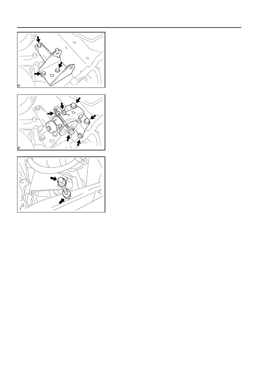
31.
REMOVE TRANSVERSE ENGINE ENGINE
MOUNTING BRACKET
(a)
Remove the 2 bolts and engine mounting bracket FR.
32.
REMOVE TRANSVERSE ENGINE ENGINE
MOUNTING BRACKET
(a)
Remove the 3 bolts and engine mounting bracket RR.
33.
REMOVE FLYWHEEL HOUSING UNDER COVER
34.
REMOVE AUTOMATIC TRANSAXLE ASSY
(a)
Turn the crankshaft to gain access and remove the 6 bolts
while holding the crankshaft pulley bolt with a wrench.
(b)
Remove the 6 bolts.
(c)
Separate and remove the automatic transaxle.
35.
REMOVE TORQUE CONVERTER CLUTCH ASSY
36.
INSPECT TORQUE CONVERTER CLUTCH ASSY (See page
40–20
)
SST
09350–32014 (09351–32010, 09351–32020)
C63993
C65911
D09966
A
B
C
F00478
40–14
–
AUTOMATIC TRANSMISSION / TRANS
AUTOMATIC TRANSAXLE ASSY (ATM)
1364
Author:
Date:
2004 COROLLA (RM1037U)
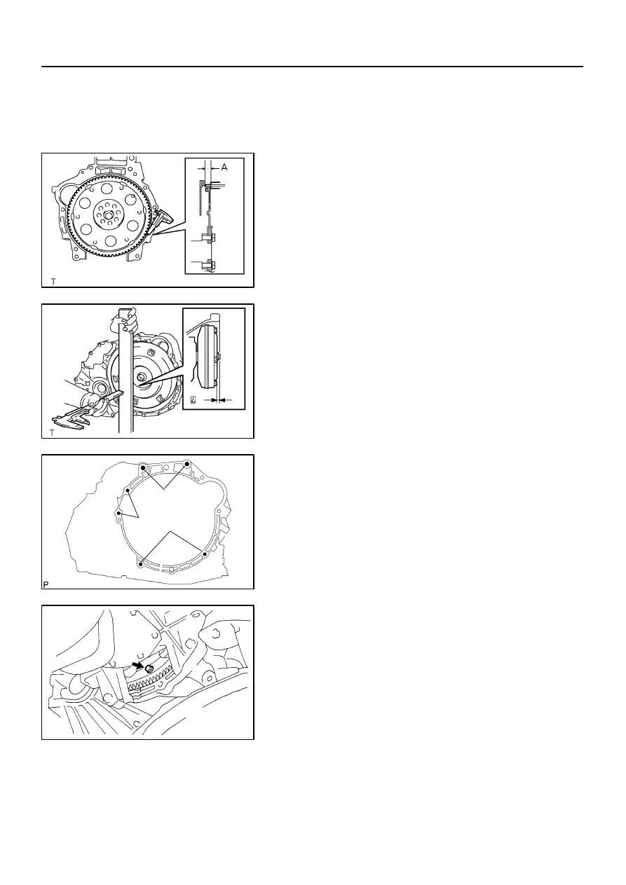
37.
INSTALL TORQUE CONVERTER CLUTCH ASSY
(a)
Install the torque converter clutch to the automatic trans-
axle.
(b)
Using vernier calipers, measure the dimension ”A” be-
tween the transaxle fitting part and the converter fitting
part of the drive plate.
(c)
Using vernier calipers and a straight edge, measure the
dimension ”B” shown in the illustration and check that ”B”
is greater than ”A” measured in (b).
Standard: A + 1 mm or more
NOTICE:
Do not add the thickness of straight edge.
38.
INSTALL AUTOMATIC TRANSAXLE ASSY
(a)
Install the automatic transaxle and 6 bolts to the engine.
Torque:
Bolt A: 64 N
⋅
m (650 kgf
⋅
cm, 47 ft
⋅
lbf)
Bolt B: 46 N
⋅
m (470 kgf
⋅
cm, 34 ft
⋅
lbf)
Bolt C: 23 N
⋅
m (235 kgf
⋅
cm, 17 ft
⋅
lbf)
(b)
Install the 6 torque converter mounting bolts.
Torque: 28 N
⋅
m (285 kgf
⋅
cm, 20 ft
⋅
lbf)
HINT:
First install yellowish green colored bolt and then the 5 bolts.
39.
INSTALL FLYWHEEL HOUSING UNDER COVER
C93645
C80172
C95354
A
B
A
B
C80192
C80167
–
AUTOMATIC TRANSMISSION / TRANS
AUTOMATIC TRANSAXLE ASSY (ATM)
40–15
1365
Author:
Date:
2004 COROLLA (RM1037U)
40.
INSTALL TRANSVERSE ENGINE ENGINE MOUNTING
BRACKET
(a)
Install the engine mounting bracket RR and 3 bolts to the
automatic transaxle.
Torque: 64 N
⋅
m (652 kgf
⋅
cm, 47 ft
⋅
lbf)
41.
INSTALL TRANSVERSE ENGINE ENGINE MOUNTING
BRACKET
(a)
Install the engine mounting bracket FR and 2 bolts to the
automatic transaxle.
Torque: 64 N
⋅
m (652 kgf
⋅
cm, 47 ft
⋅
lbf)
42.
INSTALL ENGINE MOUNTING MEMBER SUB–ASSY
CENTER
(a)
Install the dynamic damper, member sub–assy center
with engine mounting insulator FR and 4 bolts.
Torque:
Bolt A: 39 N
⋅
m (398 kgf
⋅
cm, 29 ft
⋅
lbf)
Bolt B: 52 N
⋅
m (530 kgf
⋅
cm, 38 ft
⋅
lbf)
43.
INSTALL TRANSVERSE ENGINE ENGINE MOUNTING
INSULATOR
(a)
Install the engine mounting insulator RR and bolt to the
engine mounting bracket RR.
Torque: 87 N
⋅
m (887 kgf
⋅
cm, 64 ft
⋅
lbf)
(b)
Tighten the 3 nuts and bolt.
Torque: 52 N
⋅
m (530 kgf
⋅
cm, 38 ft
⋅
lbf)
D09965
D09964
A
A
A
A
B
B
C80166
40–16
–
AUTOMATIC TRANSMISSION / TRANS
AUTOMATIC TRANSAXLE ASSY (ATM)
1366
Author:
Date:
2004 COROLLA (RM1037U)
44.
INSTALL TRANSVERSE ENGINE ENGINE MOUNTING
BRACKET
(a)
Install the engine mounting bracket LH and 3 bolts to the
automatic transaxle.
Torque: 52 N
⋅
m (530 kgf
⋅
cm, 38 ft
⋅
lbf)
45.
INSTALL TRANSVERSE ENGINE ENGINE MOUNTING
INSULATOR
(a)
Install the engine mounting insulator LH, 5 bolts and nut.
Torque:
Bolt A: 52 N
⋅
m (530 kgf
⋅
cm, 38 ft
⋅
lbf)
Bolt B: 80 N
⋅
m (815 kgf
⋅
cm, 59 ft
⋅
lbf)
Nut B: 80 N
⋅
m (815 kgf
⋅
cm, 59 ft
⋅
lbf)
46.
INSTALL TRANSVERSE ENGINE ENGINE MOUNTING
INSULATOR
(a)
Install the bolt and nut to the engine mounting bracket FR.
Torque: 52 N
⋅
m (530 kgf
⋅
cm, 38 ft
⋅
lbf)
47.
INSTALL STARTER ASSY
(a)
Install the starter and 2 bolts.
Torque: 39 N
⋅
m (400 kgf
⋅
cm, 29 ft
⋅
lbf)
(b)
Connect the connecter.
(c)
Install the starter wire and nut.
Torque: 13 N
⋅
m (132 kgf
⋅
cm, 10 ft
⋅
lbf)
48.
INSTALL AUTOMATIC TRANSMISSION CASE PROTECTOR
(a)
Install the case protector with the 2 bolts.
Torque: 18 N
⋅
m (182 kgf
⋅
cm, 14 ft
⋅
lbf)
49.
INSTALL FRONT DRIVE SHAFT ASSY LH (See page
30–6
)
50.
INSTALL FRONT DRIVE SHAFT ASSY RH (See page
30–6
)
51.
INSTALL EXHAUST PIPE ASSY FRONT (See page
15–2
)
52.
INSTALL ENGINE UNDER COVER LH
53.
INSTALL ENGINE UNDER COVER RH
54.
INSTALL FRONT WHEELS
Torque: 103 N
⋅
m (1,050 kgf
⋅
cm, 76 ft
⋅
lbf)
55.
INSTALL OXYGEN SENSOR CONNECTOR
(a)
Connect the oxygen sensor connector.
(b)
Install the floor carpet and foot rest.
D09962
C93646
SST
C93643
–
AUTOMATIC TRANSMISSION / TRANS
AUTOMATIC TRANSAXLE ASSY (ATM)
40–17
1367
Author:
Date:
2004 COROLLA (RM1037U)
56.
INSTALL TRANSMISSION OIL FILLER TUBE
SUB–ASSY
(a)
Temporarily install the oil cooler outlet tube No. 1.
(b)
Temporarily install the oil cooler inlet tube No. 1.
(c)
Coat a new O–ring with ATF, and install them to the oil filler
tube.
(d)
Install the oil filler tube to the automatic transaxle.
(e)
Install the oil cooler tube clamp and 2 bolts.
Torque: 5.5 N
⋅
m (56 kgf
⋅
cm, 49 in.
⋅
lbf)
(f)
Install the ATF lever gauge.
57.
INSTALL OIL COOLER INLET TUBE NO.1
(a)
Using SST, tighten the oil cooler inlet tube No. 1.
SST
09023–12700
Torque: 34.5 N
⋅
m (350 kgf
⋅
cm, 25 ft
⋅
lbf)
58.
INSTALL OIL COOLER OUTLET TUBE NO.1
(a)
Using SST, tighten the oil cooler outlet tube No. 1.
SST
09023–12700
Torque: 34.5 N
⋅
m (350 kgf
⋅
cm, 25 ft
⋅
lbf)
59.
CONNECT CONNECTOR
(a)
Connect the transmission wire connector.
(b)
Connect the park/neutral position switch connector.
(c)
w/o ABS:
Connect the speedometer sensor connector.
60.
INSTALL WIRE HARNESS
(a)
Install the wire harness clamp bracket and bolt.
Torque: 12.75 N
⋅
m (130 kgf
⋅
cm, 9 ft
⋅
lbf)
C93666
A
B
C
C95750
C96147
C80159
40–18
–
AUTOMATIC TRANSMISSION / TRANS
AUTOMATIC TRANSAXLE ASSY (ATM)
1368
Author:
Date:
2004 COROLLA (RM1037U)
(b)
Install the wire harness clamp bracket and 2 wire har-
nesses with the 3 bolts.
Torque:
Bolt A: 25.5 N
⋅
m (260 kgf
⋅
cm, 19 ft
⋅
lbf)
Bolt B: 10 N
⋅
m (102 kgf
⋅
cm, 7 ft
⋅
lbf)
Bolt C: 13 N
⋅
m (132 kgf
⋅
cm, 10 ft
⋅
lbf)
61.
INSTALL TRANSMISSION CONTROL CABLE BRACKET NO.1
(a)
Install the control cable bracket and 2 bolts.
Torque: 12 N
⋅
m (122 kgf
⋅
cm, 9 ft
⋅
lbf)
62.
INSTALL TRANSMISSION CONTROL CABLE
SUPPORT
(a)
Install the control cable support and bolt.
Torque: 12 N
⋅
m (122 kgf
⋅
cm, 9 ft
⋅
lbf)
(b)
Connect the control cable and wire harness to the control
cable support.
63.
INSTALL FLOOR SHIFT CABLE TRANSMISSION
CONTROL SHIFT
(a)
Temporarily install the control cable to the control shaft le-
ver with the nut.
(b)
Install the control cable and clip to the bracket.
64.
INSTALL BATTERY CARRIER
(a)
Install the battery carrier and 4 bolts.
Torque: 13 N
⋅
m (132 kgf
⋅
cm, 10 ft
⋅
lbf)
65.
INSTALL AIR CLEANER ASSEMBLY WITH HOSE
Torque: 7.0 N
⋅
m (71 kgf
⋅
cm, 62 in.
⋅
lbf)
66.
INSTALL CYLINDER HEAD COVER NO.2
Torque: 7.0 N
⋅
m (71 kgf
⋅
cm, 62 in.
⋅
lbf)

–
AUTOMATIC TRANSMISSION / TRANS
AUTOMATIC TRANSAXLE ASSY (ATM)
40–19
1369
Author:
Date:
2004 COROLLA (RM1037U)
67.
INSTALL HOOD SUB–ASSY
Torque: 13 N
⋅
m (130 kgf
⋅
cm, 10 ft
⋅
lbf)
68.
INSPECT HOOD SUB–ASSY (See page
75–1
)
69.
ADJUST HOOD SUB–ASSY (See page
75–1
)
70.
ADD AUTOMATIC TRANSAXLE FLUID
71.
INSPECT AUTOMATIC TRANSAXLE FLUID (See page
40–2
)
72.
ADJUST SHIFT LEVER POSITION (See page
40–44
)
73.
INSPECT SHIFT LEVER POSITION (See page
40–44
)
74.
INSPECT FRONT WHEEL ARIMENT (See page
26–5
)
75.
CHECK ABS SPEED SENSOR SIGNAL (W/ ABS) (See page
05–297
)
400LL–01
AT0953
SST
AT3306
Hold
Turn
Lock
Free
D25367
Sample showing minimum amount of
powders in ATF
Actual Size
40–20
–
AUTOMATIC TRANSMISSION / TRANS
TORQUE CONVERTER CLUTCH AND DRIVE
PLATE (ATM)
1370
Author:
Date:
2004 COROLLA (RM1037U)
TORQUE CONVERTER CLUTCH AND DRIVE PLATE (ATM)
INSPECTION
1.
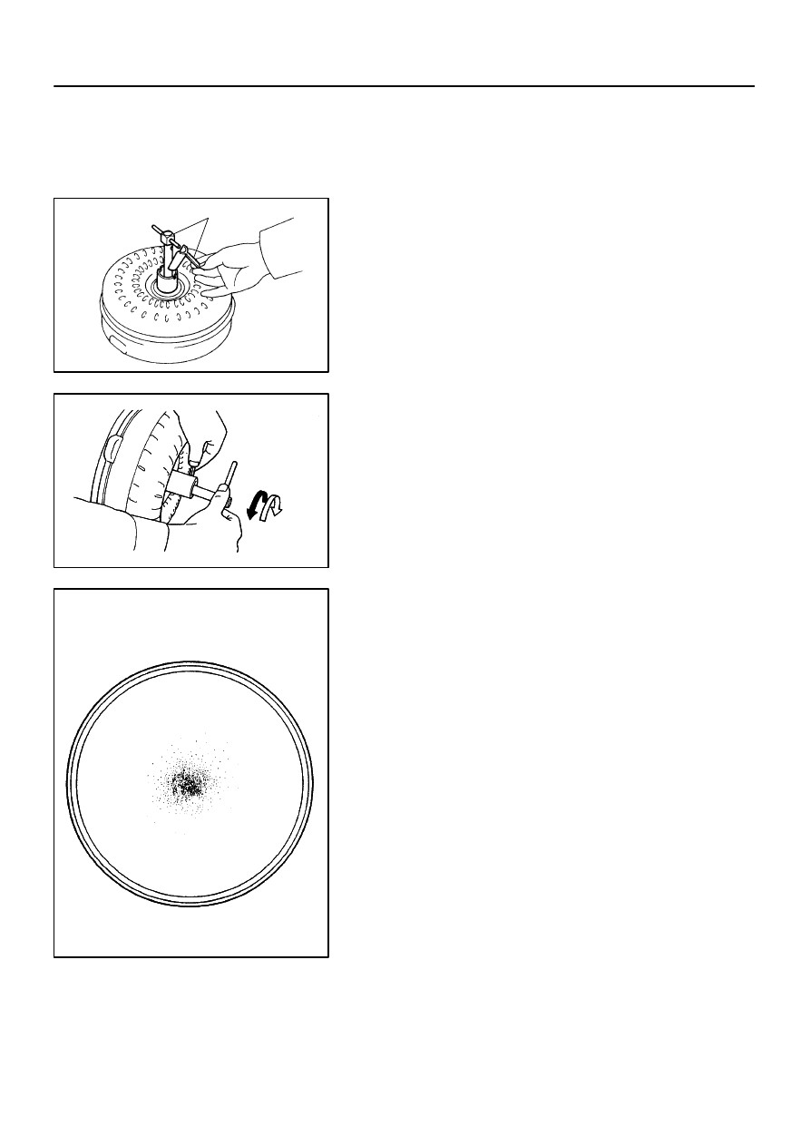
INSPECT TORQUE CONVERTER CLUTCH ASSY
(a)
Inspect the one–way clutch.
(1)
Set SST into the inner race of the one–way clutch.
SST
09350–32014 (09351–32010)
(2)
Set SST so that it fits in the notch of the converter
hub and outer race of the one–way clutch.
SST
09350–32014 (09351–32020)
(3)
With the torque converter clutch setting up on its
side, check that the one–way clutch locks when it is
turned counterclockwise, and rotates smoothly
clockwise.
If necessary, clean the torque converter clutch and retest the
one–way clutch.
Replace the torque converter clutch if the one–way clutch still
fails the test.
(b)
Determine the condition of the torque converter clutch
assy.
(1)
If the inspection result of the torque converter clutch
assy meets the following item, replace the torque
converter clutch.
Malfunction item:
Any metallic sound is heard from the torque convert-
er clutch during stall test or when the shift lever is in
neutral position.
One–way clutch is free or locked in both directions.
Fine powders exceeding the sample limit is identified
in ATF. (See the sample.)
HINT:
The sample shows the auto fluid of approx. 0.25 liters (0.26 US
qts, 0.22 Imp. qts) that is taken out from the removed torque
converter clutch
(c)
Replace the ATF in the torque converter clutch.
(1)
If the ATF is discolored and/or has a foul odor, com-
pletely stir the ATF in the torque converter clutch
and drain it with the face for installation facing up.
C11090
D25368
OK
NG
The Bottom is
Damaged
C81014
–
AUTOMATIC TRANSMISSION / TRANS
TORQUE CONVERTER CLUTCH AND DRIVE
PLATE (ATM)
40–21
1371
Author:
Date:
2004 COROLLA (RM1037U)
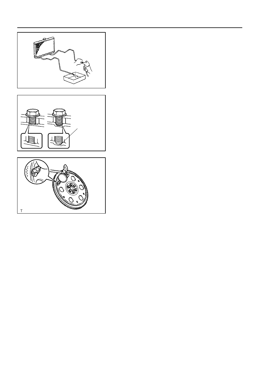
(d)
Clean and check the oil cooler and oil pipe line.
(1)
If the torque converter clutch is inspected or the ATF
is exchanged, clean the oil cooler and oil pipe line.
HINT:
Spray compressed air of 196 kPa (2 kgf/cm
2
, 28 psi) from
the inlet hose.
If plenty of fine powders are identified in the ATF, add new
ATF using a bucket pump and clean it again.
(2)
If the ATF is cloudy, inspect the oil cooler.
(e)
Prevent deformation of the torque converter clutch and
damage to the oil pump gear.
(1)
When any marks due to interference are found on
the end of the bolt for the torque converter clutch
and on the bottom of the bolt hole, replace the bolt
and the torque converter clutch.
(2)
All of the bolts should have the same length.
(3)
No missing spring washer.
2.
INSPECT DRIVE PLATE & RING GEAR SUB–ASSY
(a)
Set up a dial indicator and measure the drive plate runout.
(b)
Check the damage of the ring gear.
Maximum runout: 0.20 mm (0.0079 in.)
If the runout is not within the specification or ring gear is dam-
aged, replace the drive plate.
400LM–01
C95424
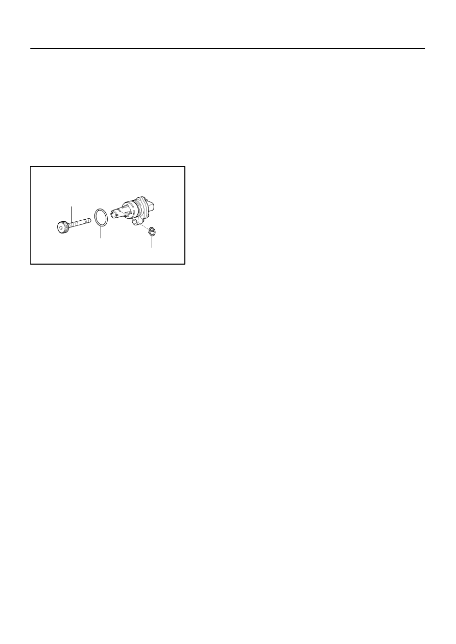
Driven Gear
O–ring
Clip
40–22
–
AUTOMATIC TRANSMISSION / TRANS
SPEEDOMETER SENSOR (ATM)
1372
Author:
Date:
2004 COROLLA (RM1037U)
SPEEDOMETER SENSOR (ATM)
REPLACEMENT
1.
REMOVE AIR CLEANER CASE
2.
REMOVE AIR CLEANER HOSE NO.1
3.
REMOVE SPEEDOMETER SENSOR
(a)
Disconnect the connector.
(b)
Remove the bolt and speedometer sensor assembly.
(c)
Remove the clip and driven gear from the speedometer
sensor.
4.
INSTALL SPEEDOMETER SENSOR
(a)
Coat a O–ring with ATF and install it to the speedometer
sensor.
(b)
Install the driven gear to the speedometer sensor with the
clip.
(c)
Install the speedometer sensor assembly with the bolt.
Torque: 11.3 N·m (115 kgf·cm, 9 ft
⋅
lbf)
(d)
Connect the connector.
5.
INSTALL AIR CLEANER HOSE NO.1
6.
INSTALL AIR CLEANER CASE
Torque: 7.0 N
⋅
m (71 kgf
⋅
cm, 62 in.
⋅
lbf)
400LN–01
D09967
AT0103
D25128
D25129
–
AUTOMATIC TRANSMISSION / TRANS
TRANSMISSION VALVE BODY ASSY (ATM)
40–23
1373
Author:
Date:
2004 COROLLA (RM1037U)
TRANSMISSION VALVE BODY ASSY (ATM)
REPLACEMENT
1.
REMOVE ENGINE UNDER COVER LH
2.
DRAIN AUTOMATIC TRANSAXLE FLUID
(a)
Remove the drain plug, gasket and drain ATF.
(b)
Install a new gasket and drain plug.
Torque: 17.5 N
⋅
m (178 kgf
⋅
cm, 13 ft
⋅
lbf)
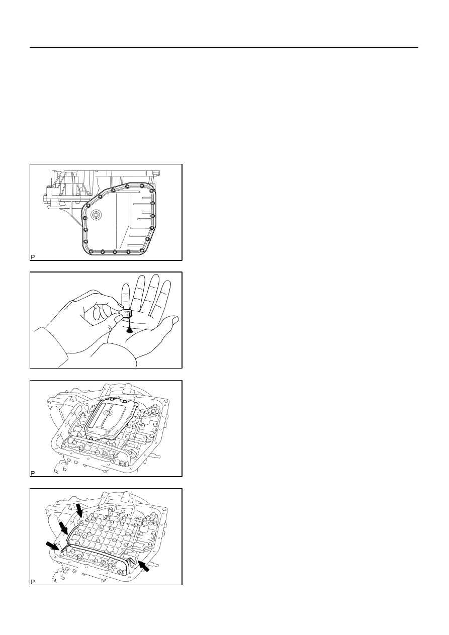
3.
REMOVE AUTOMATIC TRANSAXLE OIL PAN
SUB–ASSY
(a)
Remove the 18 bolts, oil pan and gasket.
NOTICE:
Some fluid will remain in the oil pan. Remove all pan bolts,
and carefully remove the oil pan assembly. Discard the
gasket.
(b)
Remove the 2 magnets from oil pan.
(c)
Examine particles in pan.
(1)
Remove the magnets and use them to collect any
steel chips. Look carefully at the chips and particles
in the pan and the magnet to anticipate what type
of wear you will find in the transaxle.
Steel (magnetic): bearing, gear and plate wear
Brass (non–magnetic): bearing wear
4.
REMOVE VALVE BODY OIL STRAINER ASSY
(a)
Remove the 3 bolts and oil strainer.
NOTICE:
Be careful as some fluid will come out with the oil strainer.
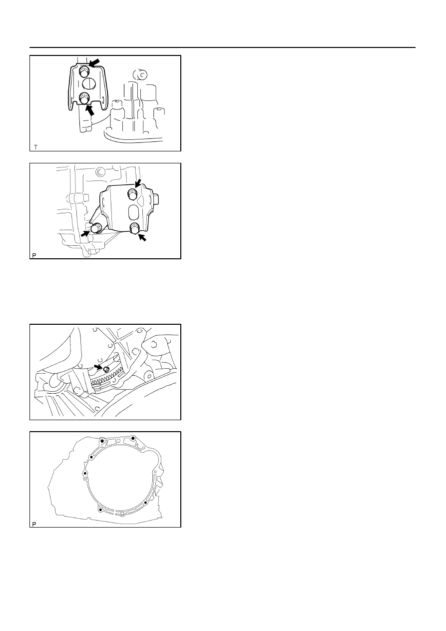
5.
REMOVE TRANSMISSION VALVE BODY ASSY
(a)
Disconnect the 4 solenoid connecters.
F00673
D25130
D25131
D25374
A
B
C
Line Pressure
Control Solenoid Assy (SLT)
Lock Plate
No.1 Solenoid Assy (S1)
Solenoid Assy
No.3 (SL)
No.2 Solenoid Assy (S2)
40–24
–
AUTOMATIC TRANSMISSION / TRANS
TRANSMISSION VALVE BODY ASSY (ATM)
1374
Author:
Date:
2004 COROLLA (RM1037U)
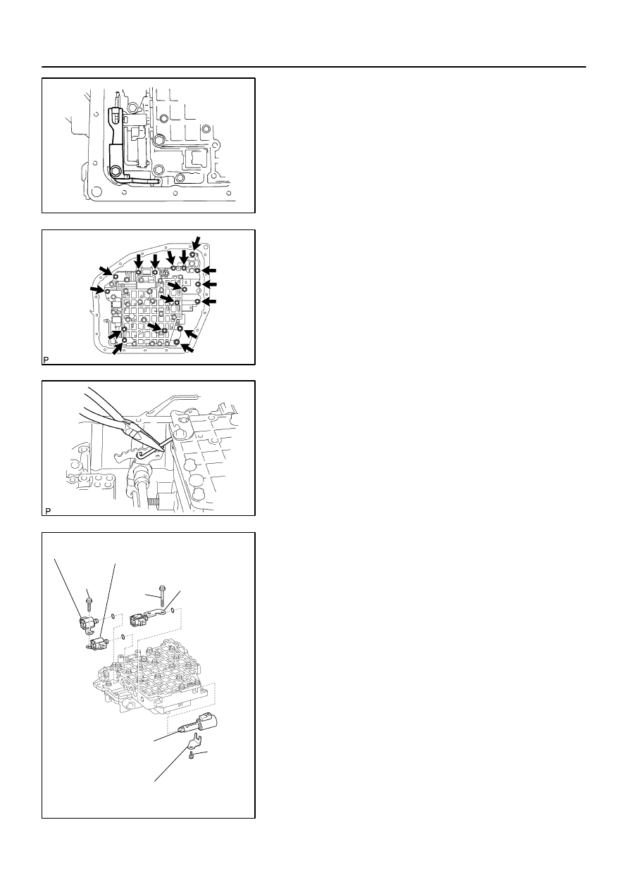
(b)
Remove the bolt and manual detent spring.
(c)
Remove the 17 bolts.
(d)
While disconnecting the manual valve connecting rod
from the manual valve lever, remove the valve body with
the manual valve together.
(e)
Remove the 2 bolts and 3 solenoid valves.
(f)
Remove the 3 O–rings from each of the solenoid valves.
(g)
Remove the bolt, lock plate and line pressure control
valve.
D25374
A
B
C
Line Pressure
Control Solenoid Assy (SLT)
Lock Plate
No.1 Solenoid Assy (S1)
Solenoid Assy
No.3 (SL)
No.2 Solenoid Assy (S2)
D25131
D25330
A
B
C
B
A
A
F00673
–
AUTOMATIC TRANSMISSION / TRANS
TRANSMISSION VALVE BODY ASSY (ATM)
40–25
1375
Author:
Date:
2004 COROLLA (RM1037U)
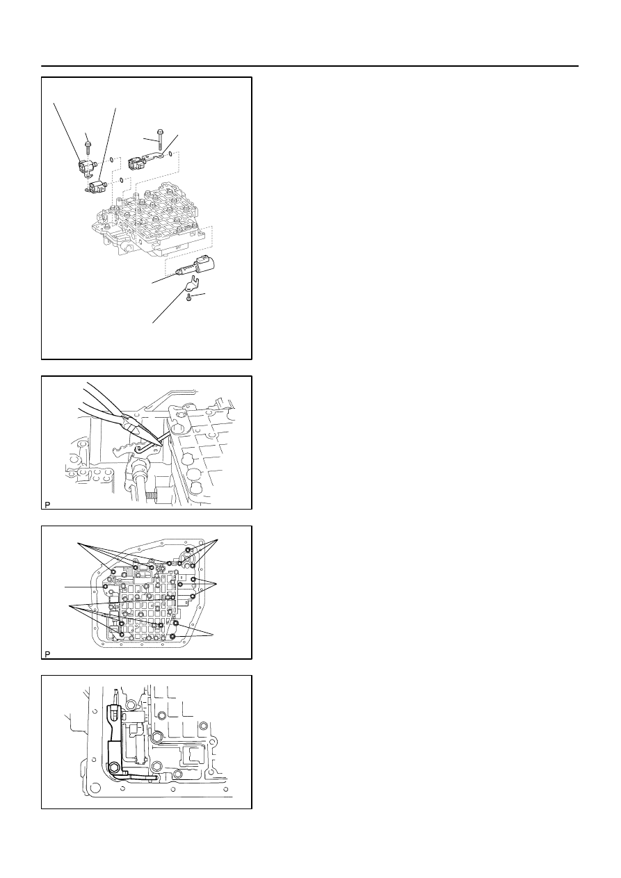
6.
INSTALL TRANSMISSION VALVE BODY ASSY
(a)
Coat 3 new O–rings with ATF and install them to each so-
lenoid valves.
(b)
Install the No.1 and No.2 solenoid valves with the bolt.
(c)
Install the No.3 solenoid valve with the bolt.
(d)
Install the line pressure control solenoid valve and lock
plate with the bolt.
Torque:
Bolt A: 11 N·m (110 kgf·cm, 8 ft·lbf)
Bolt B: 11 N·m (110 kgf·cm, 8 ft·lbf)
Bolt C: 6.5 N·m (66 kgf·cm, 58 in.
⋅
lbf)
Bolt length:
Bolt A: 25 mm (0.984 in.)
Bolt B: 60 mm (2.362 in.)
Bolt C: 12 mm (0.472 in.)
(e)
While connecting the manual valve connecting rod to the
manual valve lever, install the valve body with the manual
valve together.
(f)
Install the 17 bolts.
Bolt length:
Bolt A: 20 mm (0.79 in.)
Bolt B: 28 mm (1.10 in.)
Bolt C: 50 mm (1.97 in.)
Torque: 10 N·m (100 kgf·cm, 7 ft·lbf)
(g)
Install the manual detent spring and bolt.
Torque: 10 N·m (100 kgf·cm, 7 ft·lbf)
D25129
D25128
A
B
D08582
Magnet
D09967
40–26
–
AUTOMATIC TRANSMISSION / TRANS
TRANSMISSION VALVE BODY ASSY (ATM)
1376
Author:
Date:
2004 COROLLA (RM1037U)
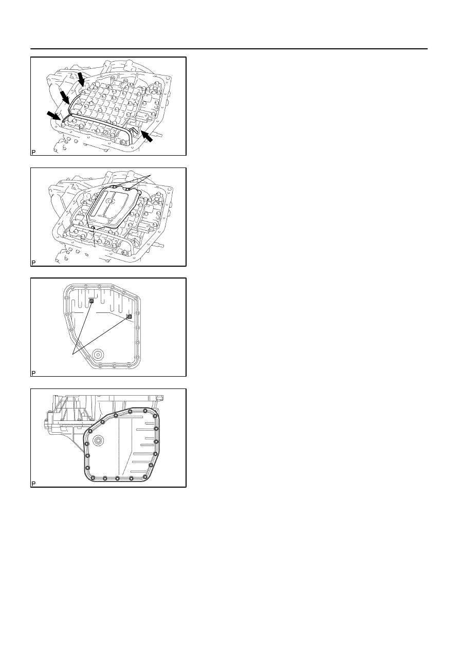
(h)
Connect the 4 solenoid connectors.
7.
INSTALL VALVE BODY OIL STRAINER ASSY
(a)
Install the oil strainer with the 3 bolts.
Bolt length:
A bolt: 12 mm (0.47 in.)
B bolt: 20 mm (0.79 in.)
Torque: 10 N·m (100 kgf·cm, 7 ft·lbf)
8.
INSTALL AUTOMATIC TRANSAXLE OIL PAN
SUB–ASSY
(a)
Install the 2 magnets to the oil pan.
(b)
Install a new gasket to the oil pan and install them to the
transaxle.
(c)
Install the 18 bolts.
Torque: 5.3 N·m (55 kgf·cm, 48 in.
⋅
lbf)
9.
INSTALL ENGINE UNDER COVER LH
10.
ADD AUTOMATIC TRANSAXLE FLUID
11.
INSPECT AUTOMATIC TRANSAXLE FLUID (See page
40–2
)
400LO–01
D09968
D09968
–
AUTOMATIC TRANSMISSION / TRANS
TRANSMISSION WIRE (ATM)
40–27
1377
Author:
Date:
2004 COROLLA (RM1037U)
TRANSMISSION WIRE (ATM)
REPLACEMENT
1.
REMOVE TRANSMISSION VALVE BODY ASSY (See page
40–23
)
2.
REMOVE TRANSMISSION WIRE
(a)
Disconnect the transmission wire connector.
(b)
Removal the bolt and transmission wire.
3.
INSTALL TRANSMISSION WIRE
(a)
Coat a O–ring with ATF.
(b)
Install the transmission wire and bolt.
Torque: 5.4 N
⋅
m (55 kgf
⋅
cm, 48 in.
⋅
lbf)
(c)
Connect the transmission wire connector.
4.
INSTALL TRANSMISSION VALVE BODY ASSY (See page
40–23
)
400LP–02
D25133
SST
Z02840
SST
D25134
SST
40–28
–
AUTOMATIC TRANSMISSION / TRANS
FRONT DIFFERENTIAL OIL SEAL (ATM)
1378
Author:
Date:
2004 COROLLA (RM1037U)
FRONT DIFFERENTIAL OIL SEAL (ATM)
REPLACEMENT
1.
REMOVE FRONT WHEELS
2.
REMOVE ENGINE UNDER COVER RH
3.
REMOVE ENGINE UNDER COVER LH
4.
DRAIN AUTOMATIC TRANSAXLE FLUID
(a)
Remove the drain plug, gasket and drain ATF.
(b)
Install a new gasket and drain plug.
Torque: 17.5 N
⋅
m (178 kgf
⋅
cm, 13 ft
⋅
lbf)
5.
REMOVE FRONT DRIVE SHAFT ASSY RH (See page
30–6
)
6.
REMOVE FRONT DRIVE SHAFT ASSY LH (See page
30–6
)
7.
REMOVE TRANSAXLE HOUSING OIL SEAL(RH)
(a)
Using SST, pull out the oil seal.
SST
09308–00010
8.
REMOVE TRANSAXLE CASE OIL SEAL(LH)
(a)
Using SST, pull out the oil seal.
SST
09308–00010
9.
INSTALL TRANSAXLE HOUSING OIL SEAL(RH)
(a)
Using SST and a hammer, drive in a new oil seal.
SST
09350–32014 (09351–32130, 09351–32150)
Oil seal drive in depth:
2.0
0.5 mm (0.079
0.020 in.)
(b)
Coat the lip of the oil seal with MP grease.
Z02841
SST
–
AUTOMATIC TRANSMISSION / TRANS
FRONT DIFFERENTIAL OIL SEAL (ATM)
40–29
1379
Author:
Date:
2004 COROLLA (RM1037U)
10.
INSTALL TRANSAXLE CASE OIL SEAL(LH)
(a)
Using SST and a hammer, drive in a new oil seal.
SST
09350–32014 (09351–32111, 09351–32130)
Oil seal drive in depth:
5.3
0.5 mm (0.209
0.020 in.)
(b)
Coat the lip of the oil seal with MP grease.
11.
INSTALL FRONT DRIVE SHAFT ASSY LH (See page
30–6
)
12.
INSTALL FRONT DRIVE SHAFT ASSY RH (See page
30–6
)
13.
INSTALL ENGINE UNDER COVER LH
14.
INSTALL ENGINE UNDER COVER RH
15.
INSTALL FRONT WHEELS
Torque: 103 N
⋅
m (1050 kgf
⋅
cm, 76 ft
⋅
lbf)
16.
ADD AUTOMATIC TRANSAXLE FLUID
17.
INSPECT AUTOMATIC TRANSAXLE FLUID (See page
40–2
)
18.
INSPECT AND ADJUST FRONT WHEEL ALIGNMENT (See page
26–5
)
19.
CHECK ABS SPEED SENSOR SIGNAL (W/ ABS) (See page
05–297
)
400LV–01
C63995
IG
E
STP
40–30
–
AUTOMATIC TRANSMISSION / TRANS
SHIFT LOCK SYSTEM (ATM)
1380
Author:
Date:
2004 COROLLA (RM1037U)
SHIFT LOCK SYSTEM (ATM)
ON–VEHICLE INSPECTION
1.
CHECK SHIFT LOCK OPERATION
(a)
Shift the shift lever to P position.
(b)
Turn the ignition switch to LOCK.
(c)
Check that the shift lever cannot be shifted to any other positions other than P.
(d)
Turn the ignition switch to ON, depress the brake pedal and check that the shift lever can be shifted
to any other positions.
2.
CHECK SHIFT LOCK RELEASE BUTTON OPERATION
(a)
Using a screwdriver, remove the shift lock release button cover.
(b)
When operating the shift lever with the shift lock release button pressed and the ignition key in ACC
or ON, check that the lever can be shifted to any other positions.
3.
CHECK KEY INTERLOCK OPERATION
(a)
Turn the ignition switch to ON.
(b)
Depress the brake pedal and shift the shift lever to any other positions other than P.
(c)
Check that the ignition key cannot be turned to LOCK.
(d)
Shift the shift lever to P position, turn the ignition key to LOCK and check that the ignition key can be
removed.
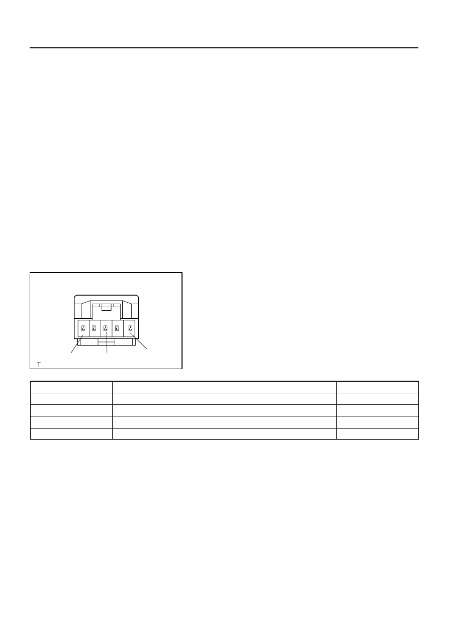
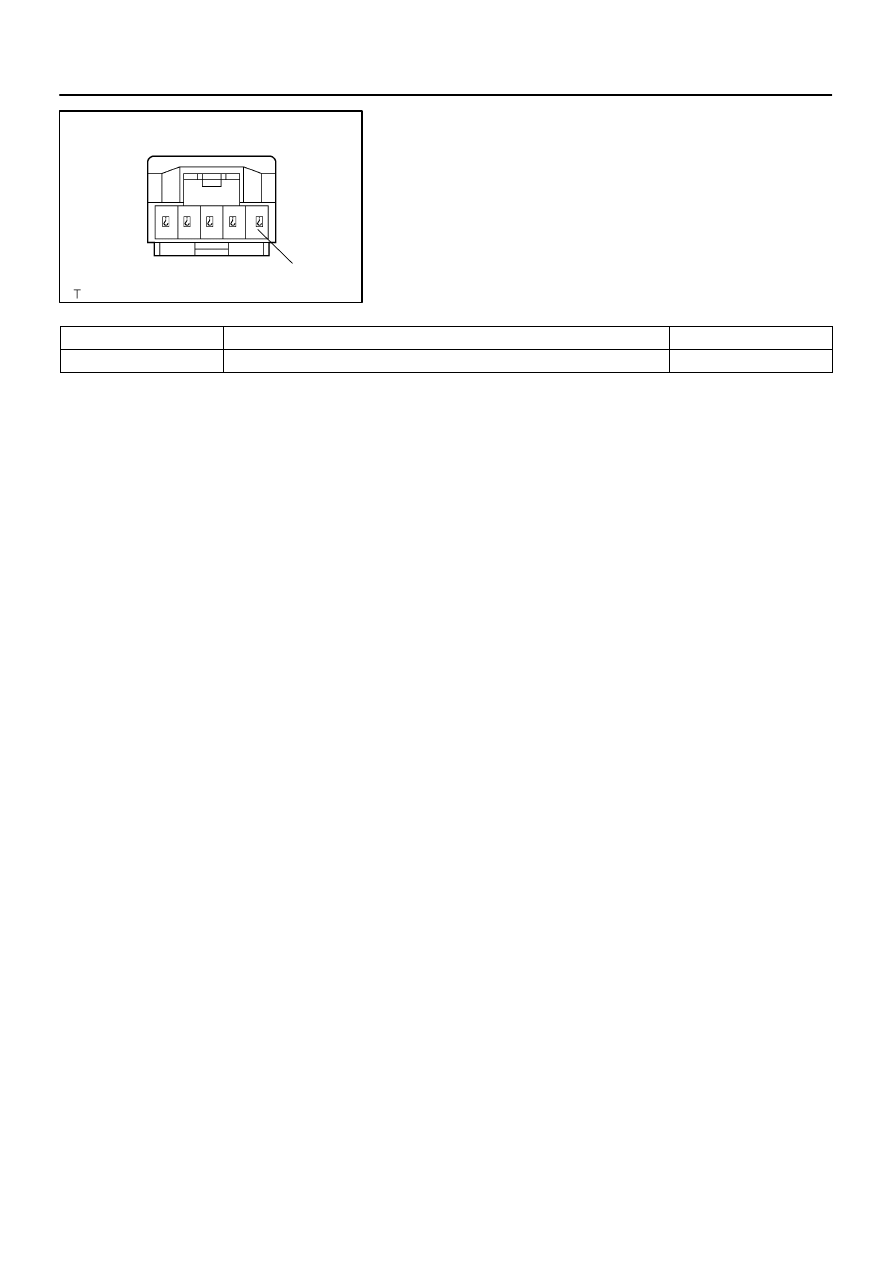
4.
INSPECT SHIFT LOCK CONTROL ECU
(a)
Using a voltmeter, measure the voltage at each terminal.
HINT:
Do not disconnect the shift lock control ECU connector.
Terminal
Measuring Condition
Voltage (V)
5 (IG) – 1 (E)
Ignition switch ON
10 – 14
5 (IG) – 1 (E)
Ignition switch OFF
0
3 (STP) – 1 (E)
Depress brake pedal
10 – 14
3 (STP) – 1 (E)
Release brake pedal
0
C63995
E
–
AUTOMATIC TRANSMISSION / TRANS
SHIFT LOCK SYSTEM (ATM)
40–31
1381
Author:
Date:
2004 COROLLA (RM1037U)
(b)
Using an ohmmeter, measure the resistance at terminal
E (1) and body ground.
Terminal
Measuring Condition
Specified Value
1 (E) – Body ground
Always
Continuity
400LQ–01
C95783
N
⋅
m (kgf
⋅
cm, ft
⋅
lbf)
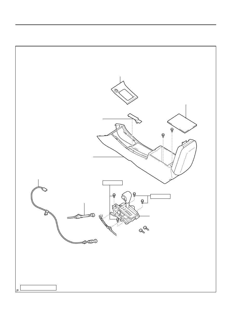
: Specified torque
Console Panel Upper
Parking Brake Hole Cover Sub–assy
Console Box Sub–assy Rear
Floor Shift Parking Lock Cable Assy
Floor Shift Cable Transmission
Control Shift
Floor Shift Assy
12 (122, 9)
12 (122, 9)
Console Box Carpet
40–32
–
AUTOMATIC TRANSMISSION / TRANS
FLOOR SHIFT ASSY (ATM)
1382
Author:
Date:
2004 COROLLA (RM1037U)
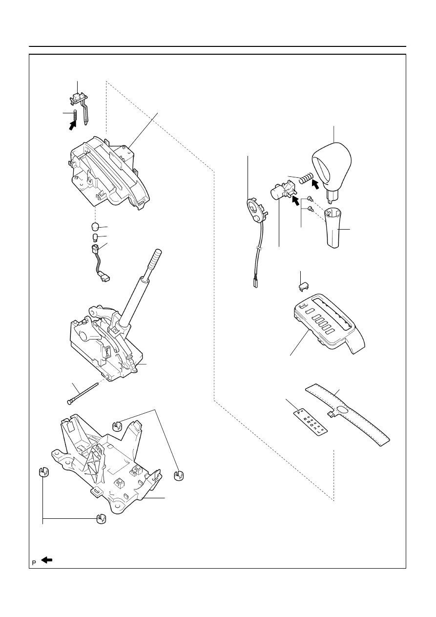
FLOOR SHIFT ASSY (ATM)
COMPONENTS
C93668
C93668
Apply MP grease
Precoated part
Spring
Position Indicator Housing Lower
Shift Lever Knob Sub–assy
Shift Lever
Knob Cover
Shift Lock Release Button
Cap
Bulb
Indicator Lamp Wire Sub–assy
Shift Lock Control
Unit Assy
Toggle Lever
Support Pin
Shift Lever Insert No.1
Shift Lever Plate Sub–assy
Shift Lever
Insert No.1
Control Position
Indicator Plate
Position Indicator
Slide Cover
Position Indicator Housing Upper
Transmission Control Switch
Shift Lock Release Button Cover
Spring
Shift Lever Knob Button
–
AUTOMATIC TRANSMISSION / TRANS
FLOOR SHIFT ASSY (ATM)
40–33
1383
Author:
Date:
2004 COROLLA (RM1037U)
400LR–01
C93669
C94276
C93670
C94278
40–34
–
AUTOMATIC TRANSMISSION / TRANS
FLOOR SHIFT ASSY (ATM)
1384
Author:
Date:
2004 COROLLA (RM1037U)
OVERHAUL
1.
REMOVE CONSOLE PANEL UPPER (See page
71–10
)
2.
REMOVE CONSOLE BOX CARPET (See page
71–10
)
3.
REMOVE PARKING BRAKE HOLE COVER SUB–ASSY (See page
71–10
)
4.
REMOVE CONSOLE BOX SUB–ASSY REAR (See page
71–10
)
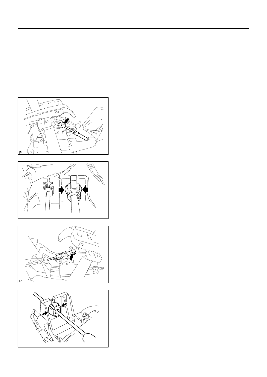
5.
DISCONNECT FLOOR SHIFT CABLE TRANSMISSION
CONTROL SHIFT
(a)
Remove the cable end from the rod of the floor shift as-
sembly.
(b)
Using a screw driver, disconnect the control cable from
the shift lever plate.
6.
DISCONNECT FLOOR SHIFT PARKING LOCK CABLE
ASSY
(a)
Remove the cable end from the lever pin of the floor shift
assembly.
(b)
Using a screw driver, disconnect the parking lock cable
from the floor shift assembly.
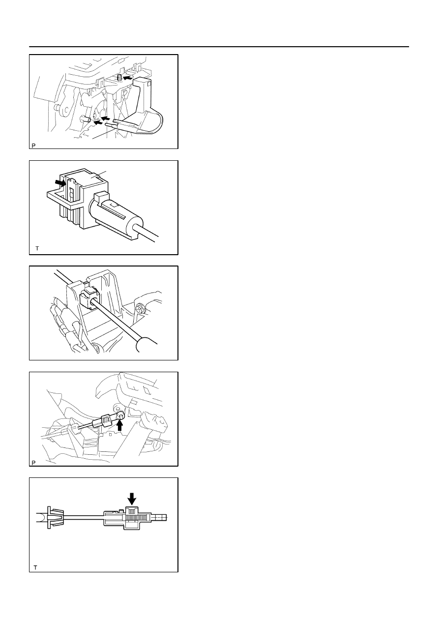
7.
REMOVE FLOOR SHIFT ASSY
(a)
Disconnect the 2 connector.
C93671
C93672
C95784
Secondary Locking Device
1
3
2
2
4
C93673
C93674
–
AUTOMATIC TRANSMISSION / TRANS
FLOOR SHIFT ASSY (ATM)
40–35
1385
Author:
Date:
2004 COROLLA (RM1037U)
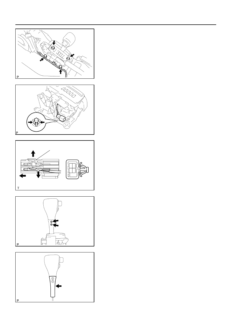
(b)
Disconnect the 2 wire harness clamps from the shift lever
assy.
(c)
Remove the 4 bolts and floor shift assy.
8.
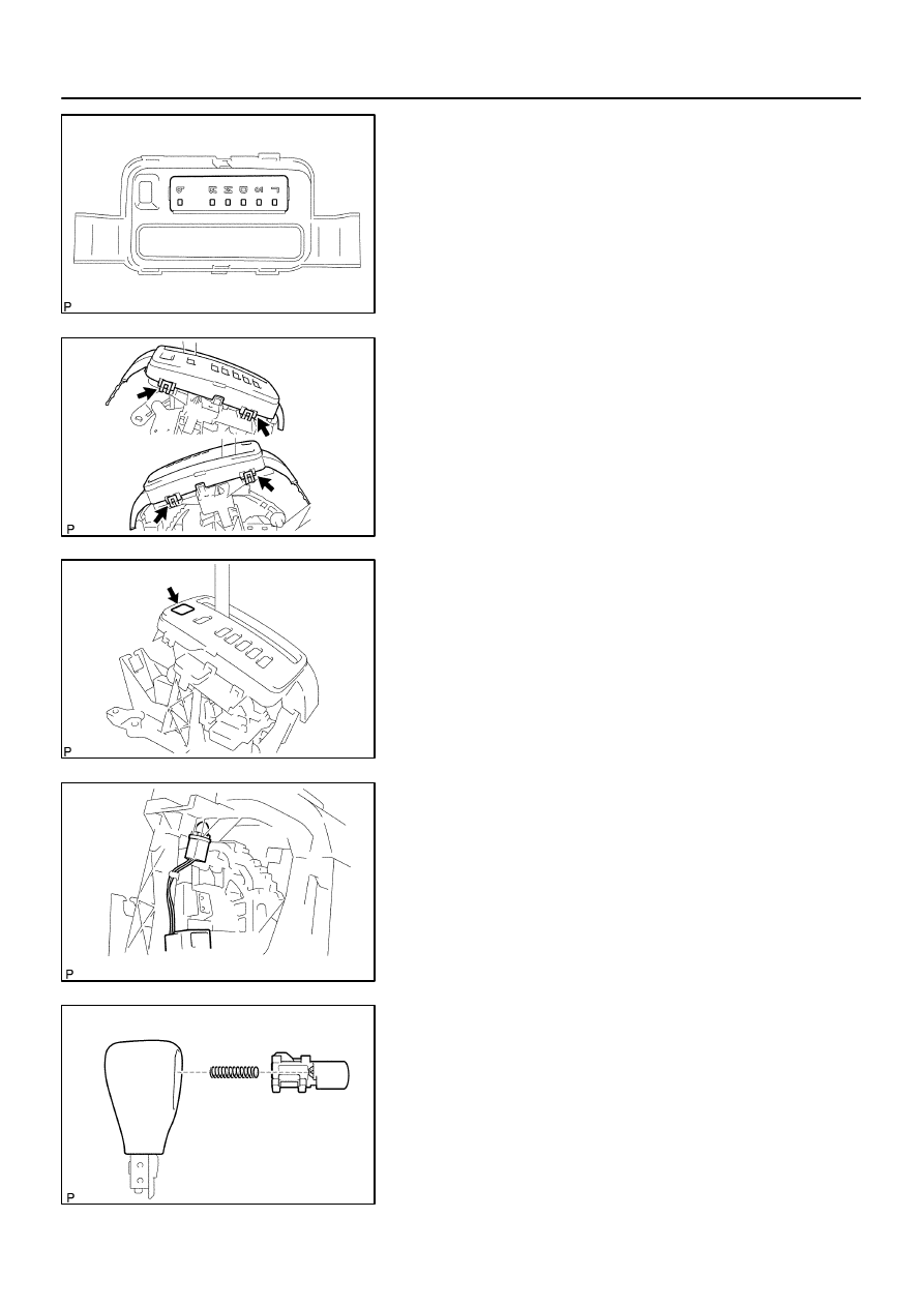
REMOVE FLOOR SHIFT SHIFT LEVER KNOB
SUB–ASSY
(a)
Releasing the lock by pressing the slick, disconnect the
indicator lamp wire connector from the shift lever plate.
(b)
Disengage the secondary locking device.
(c)
Using a small screwdriver, disengage the locking lug of
the terminals 2 and 4, and pull the terminals out from the
rear.
(d)
Disconnect the wire harness from the clamps.
(e)
Remove the 2 screws and shift lever knob sub–assembly.
NOTICE:
Pay attention not to apply unnatural load to transmission
control switch wire harness.
9.
REMOVE FLOOR SHIFT SHIFT LEVER KNOB COVER
(a)
Remove the shift lever knob cover.
C93675
C93676
C93677
C93678
C93679
40–36
–
AUTOMATIC TRANSMISSION / TRANS
FLOOR SHIFT ASSY (ATM)
1386
Author:
Date:
2004 COROLLA (RM1037U)
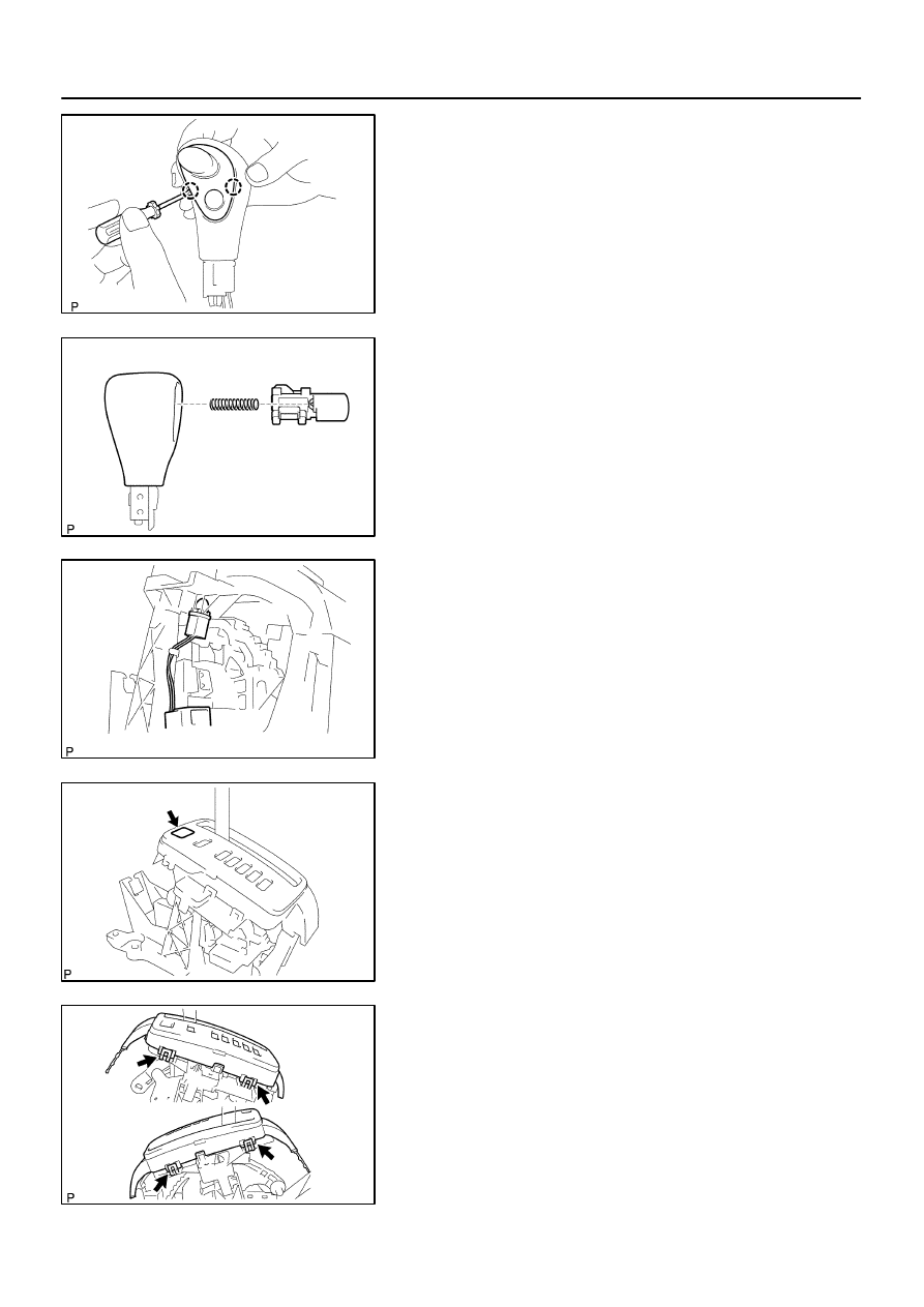
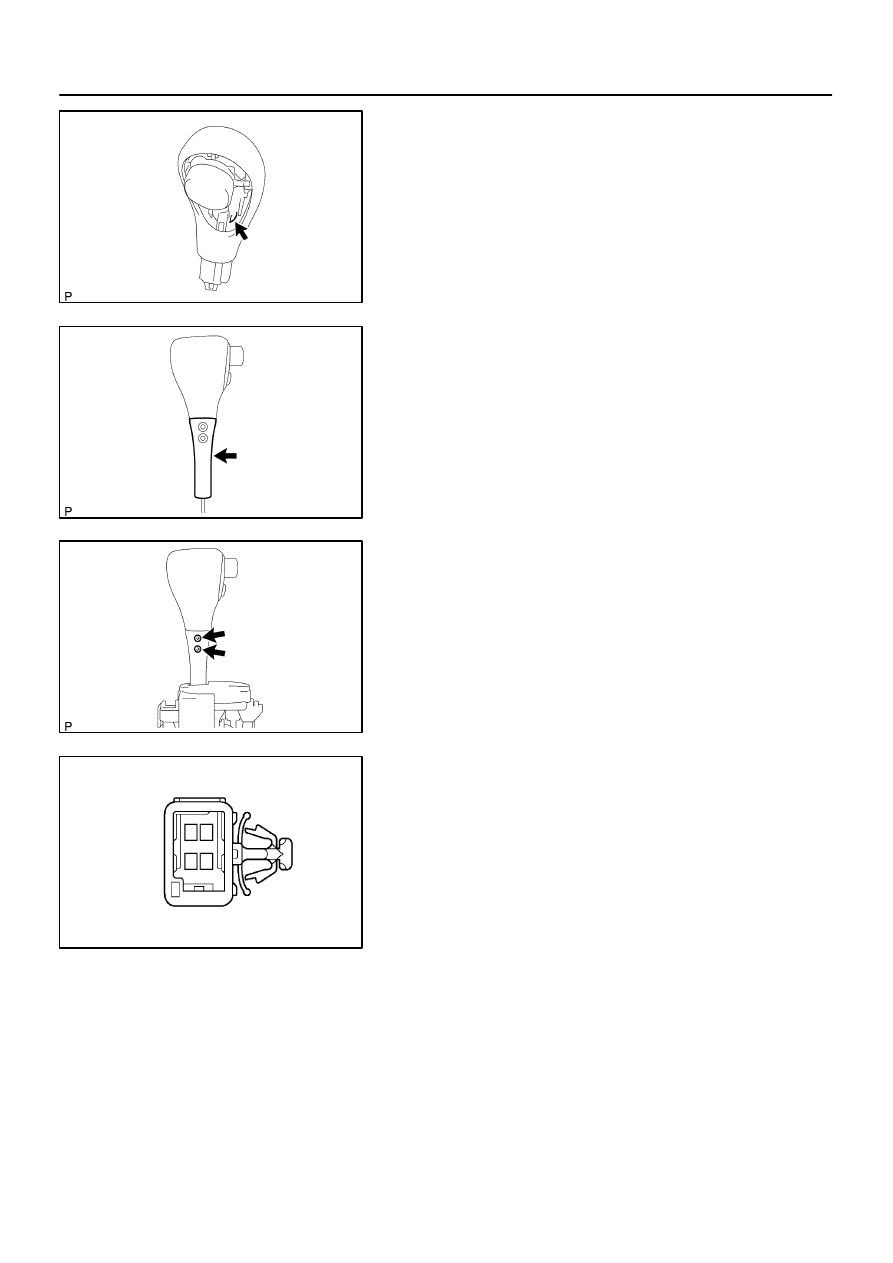
10.
REMOVE TRANSMISSION CONTROL SWITCH
(a)
Using a small screw driver, remove the transmission con-
trol switch.
11.
REMOVE SHIFT LEVER KNOB BUTTON
(a)
Remove the shift lever knob button and spring.
12.
REMOVE INDICATOR LAMP WIRE SUB–ASSY
(a)
Remove the indicator lamp wire sub–assy.
(b)
Remove the cap and bulb from the indicator lamp wire
sub–assy.
13.
REMOVE SHIFT LOCK RELEASE BUTTON COVER
(a)
Using a screwdriver, remove the shift lock release button
cover.
14.
REMOVE POSITION INDICATOR HOUSING UPPER
(a)
Using a screwdriver, release the 4 claws and remove the
position indicator housing upper.
C93680
C95340
C95341
C95342
C95343
Stopper
–
AUTOMATIC TRANSMISSION / TRANS
FLOOR SHIFT ASSY (ATM)
40–37
1387
Author:
Date:
2004 COROLLA (RM1037U)
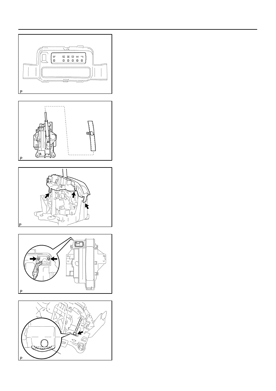
15.
REMOVE CONTROL POSITION INDICATOR PLATE
(a)
Remove the position indicator plate from the position indi-
cator housing upper.
16.
REMOVE POSITION INDICATOR SLIDE COVER
(a)
Remove the position indicator slide cover.
17.
REMOVE POSITION INDICATOR HOUSING LOWER
(a)
Using a screwdriver, release the 3 claws and remove the
position indicator housing lower.
18.
REMOVE SHIFT LOCK RELEASE BUTTON
(a)
Remove the shift lock release button and spring.
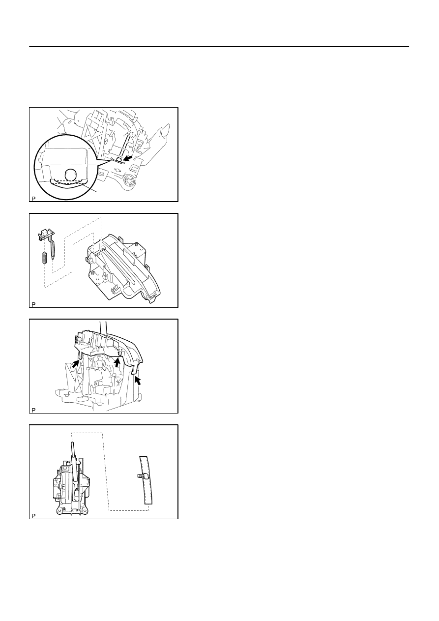
19.
REMOVE SHIFT LOCK CONTROL UNIT ASSY
(a)
Using a screwdriver, remove the toggle lever support pin
and shift lock control unit assy.
NOTICE:
Work so as not to damage the stopper position.
C95343
Stopper
C95344
C95341
C95340
40–38
–
AUTOMATIC TRANSMISSION / TRANS
FLOOR SHIFT ASSY (ATM)
1388
Author:
Date:
2004 COROLLA (RM1037U)
20.
REMOVE SHIFT LEVER INSERT NO.1
21.
INSTALL SHIFT LEVER INSERT NO.1
22.
INSTALL SHIFT LOCK CONTROL UNIT ASSY
(a)
Install the shift lock control unit assy and toggle lever sup-
port pin.
NOTICE:
Work so as not to damage the stopper position.
23.
INSTALL SHIFT LOCK RELEASE BUTTON
(a)
Apply MP grease on the shift lock release spring and shift
lock release button.
(b)
Install the shift lock release button and shift lock release
spring to the position indicator housing lower.
HINT:
Fit the claws securely.
24.
INSTALL POSITION INDICATOR HOUSING LOWER
(a)
Install the position indicator housing lower.
HINT:
Fit the claws securely.
25.
INSTALL POSITION INDICATOR SLIDE COVER
(a)
Install the position indicator slide cover.
C93680
C93679
C93678
C93677
C93676
–
AUTOMATIC TRANSMISSION / TRANS
FLOOR SHIFT ASSY (ATM)
40–39
1389
Author:
Date:
2004 COROLLA (RM1037U)
26.
INSTALL CONTROL POSITION INDICATOR PLATE
(a)
Install the position indicator plate to the position indicator
housing upper.
27.
INSTALL POSITION INDICATOR HOUSING UPPER
(a)
Install the position indicator housing upper.
HINT:
Fit the claws securely.
28.
INSTALL SHIFT LOCK RELEASE BUTTON COVER
(a)
Install the shift lock release button cover to the position in-
dicator housing upper.
29.
INSTALL INDICATOR LAMP WIRE SUB–ASSY
(a)
Install the bulb and cap to the indicator lamp wire sub–
assy.
(b)
Install the indicator lamp wire sub–assy.
30.
INSTALL SHIFT LEVER KNOB BUTTON
(a)
Apply MP grease to the spring and shift lever knob button.
(b)
Install the spring and shift lever knob button.
HINT:
Fit the claws securely.
C95345
C93674
C93673
2
4
C95819
40–40
–
AUTOMATIC TRANSMISSION / TRANS
FLOOR SHIFT ASSY (ATM)
1390
Author:
Date:
2004 COROLLA (RM1037U)
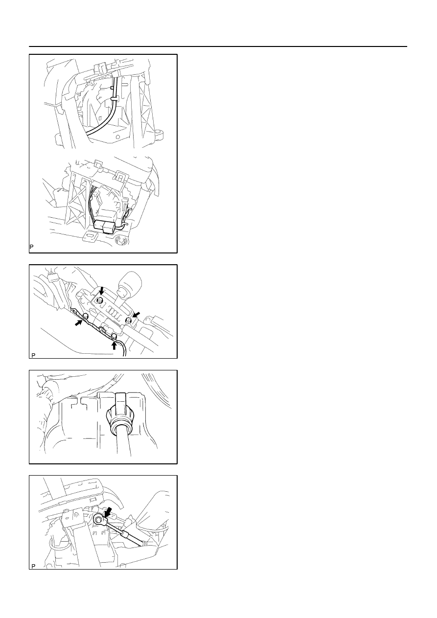
31.
INSTALL TRANSMISSION CONTROL SWITCH
(a)
Insert the wire harness into the shift lever knob from the
part shown by the arrow, and install the transmission con-
trol switch to the shift lever knob.
HINT:
Fit the claws securely.
32.
INSTALL FLOOR SHIFT SHIFT LEVER KNOB COVER
(a)
Install the shift lever knob cover.
33.
INSTALL FLOOR SHIFT SHIFT LEVER KNOB
SUB–ASSY
(a)
Install the shift lever knob sub–assembly with the 2
screws.
HINT:
Coat the threads of screws with sealant.
Sealant:
Part No. 08833–00080, THREE BOND 1344, LOCTITE
242 or equivalent
NOTICE:
Make sure not to catch wire harness.
(b)
Install the 2 terminals into the indicator lamp wire connec-
tor.
C95346
C93671
B
D
C
A
C95820
C93669
–
AUTOMATIC TRANSMISSION / TRANS
FLOOR SHIFT ASSY (ATM)
40–41
1391
Author:
Date:
2004 COROLLA (RM1037U)
(c)
Install the wire harness and connector as shown in the il-
lustration.
34.
INSTALL FLOOR SHIFT ASSY
(a)
Install the floor shift assy with the 4 bolts.
Torque: 12 N
⋅
m (122 kgf
⋅
cm, 9 ft
⋅
lbf)
HINT:
Tighten them in the order, A, B, C and D.
(b)
Connect the 2 wire harness clamps to the shift lever plate.
(c)
Connect the 2 connector.
35.
CONNECT FLOOR SHIFT CABLE TRANSMISSION
CONTROL SHIFT
(a)
Install the control cable to the shift lever plate.
HINT:
Fit the claws securely.
(b)
Install the cable end to the rod of the floor shift assy.
HINT:
Install it with the uneven surface facing upward.
C95347
Accessory tool
D25385
Lock Key
C94298
C93670
C63997
40–42
–
AUTOMATIC TRANSMISSION / TRANS
FLOOR SHIFT ASSY (ATM)
1392
Author:
Date:
2004 COROLLA (RM1037U)
36.
CONNECT FLOOR SHIFT PARKING LOCK CABLE
ASSY
(a)
Set the accessory tool.
(1)
Shift the shift lever to N position and turn the ignition
switch to ACC or ON.
(2)
Set the accessory tool to the shift lock control unit
assy as shown in the illustration.
Accessory tool parts No.: 33693–02010
HINT:
Only in the case of reusing the shift lock control unit assy.
(b)
Using a screwdriver, unlock the claw of the lock key of au-
tomatic adjustment parts.
(c)
Insert the slide cap into the through hole and install.
HINT:
Fit the claws securely.
(d)
Insert the lever pin into the hole in the cable end.
HINT:
Fit the claws securely.
(e)
Lock the lock key.
HINT:
At this time, the shift lever should be in N position and the igni-
tion key should be set to ACC or ON.
(f)
Remove the accessory tool.
Accessory tool parts No.: 33693–02010

–
AUTOMATIC TRANSMISSION / TRANS
FLOOR SHIFT ASSY (ATM)
40–43
1393
Author:
Date:
2004 COROLLA (RM1037U)
37.
CHECK KEY INTERLOCK OPERATION (See page
40–30
)
38.
CHECK SHIFT LOCK OPERATION (See page
40–30
)
39.
CHECK SHIFT LOCK RELEASE BUTTON OPERATION (See page
40–30
)
400LS–01
C95423
With the brake pedal depressed,
shift while holding the shift lever
knob button in. (The ignition
switch must be in ON position.)
Shift normally
Shift while holding the shift
lever knob button in.
D25118
D25119
40–44
–
AUTOMATIC TRANSMISSION / TRANS
FLOOR SHIFT ASSY (ATM)
1394
Author:
Date:
2004 COROLLA (RM1037U)
ADJUSTMENT
1.
INSPECT SHIFT LEVER POSITION
(a)
When shifting the shift lever to each position, make sure
that it moves smoothly, and the position indicator displays
correctly.
Positions which can be shifted without pressing the
shift lever knob button
R
→
N
→
D, L
→
2
→
D
→
N
Positions which can be operated only while pressing
the shift lever knob button
D
→
2
→
L, N
→
R
→
P
Positions which can be operated only while pressing
the shift lever knob button, ignition switch ON and
brake pedal depressed
P
→
R
(b)
Start the engine and make sure that the vehicle moves
forward when shifting the lever from N to D position, and
moves rearward when shifting to R position.
2.
ADJUST SHIFT LEVER POSITION
(a)
Loosen the nut on the control shaft lever.
(b)
Push the control shaft fully downward.
(c)
Return the control shaft lever 2 notches to N position.
(d)
Set the shift lever to N position.
(e)
While holding the shift lever lightly toward the R position
side, tighten the shift lever nut.
Torque: 12 N·m (122 kgf·cm, 9 ft·lbf)
(f)
Start the engine and make sure that the vehicle moves
forward when shifting the lever from N to D position and
moves rearward when shifting it to R position.
400LT–01
C96147
C80196
–
AUTOMATIC TRANSMISSION / TRANS
FLOOR SHIFT CABLE TRANSMISSION CONTROL
SHIFT (ATM)
40–45
1395
Author:
Date:
2004 COROLLA (RM1037U)
FLOOR SHIFT CABLE TRANSMISSION CONTROL
SHIFT (ATM)
REPLACEMENT
1.
PRECAUTION (See page
60–1
)
2.
DISCONNECT BATTERY NEGATIVE TERMINAL
3.
REMOVE PARKING BRAKE HOLE COVER SUB–ASSY (See page
71–10
)
4.
REMOVE CONSOLE PANEL UPPER (See page
71–10
)
5.
REMOVE CONSOLE BOX CARPET (See page
71–10
)
6.
REMOVE CONSOLE BOX SUB–ASSY REAR (See page
71–10
)
7.
REMOVE AIR BAG SENSOR ASSY CENTER (See page
60–38
)
8.
DISCONNECT OXYGEN SENSOR CONNECTOR
(a)
Remove the foot rest.
(b)
Pull up the floor carpet.
(c)
Disconnect the oxygen sensor connector.
9.
REMOVE FLOOR PANEL BRACE FRONT
(a)
Remove the 2 nuts and floor panel brace.
10.
REMOVE EXHAUST PIPE ASSY FRONT (See page
15–2
)
11.
REMOVE FRONT FLOOR HEAT INSULATOR NO.1
(a)
Remove the 3 nuts and heat insulator.
12.
REMOVE AIR CLEANER CASE
13.
REMOVE AIR CLEANER HOSE NO.1
14.
REMOVE FLOOR SHIFT CABLE TRANSMISSION
CONTROL SHIFT
(a)
Remove the nut from control shaft lever.
(b)
Disconnect the control cable from the control shaft lever.
(c)
Remove the clip and disconnect the control cable from
the control cable bracket.
(d)
Disconnect the control cable from the control cable sup-
port.
(e)
Remove the 2 nuts.
C93669
C94276
C80197
C80197
C94297
40–46
–
AUTOMATIC TRANSMISSION / TRANS
FLOOR SHIFT CABLE TRANSMISSION CONTROL
SHIFT (ATM)
1396
Author:
Date:
2004 COROLLA (RM1037U)
(f)
Remove the cable end from the rod of the floor shift as-
sembly.
(g)
Using a screw driver, disconnect the control cable from
the shift lever plate.
(h)
Remove the 2 bolts.
(i)
Pull out the control cable assy from the body.
(j)
Remove the retainer from the shift cable.
15.
INSTALL FLOOR SHIFT CABLE TRANSMISSION
CONTROL SHIFT
(a)
Install the retainer to the shift cable.
(b)
Pull in the control cable assy to the body.
(c)
Install the 2 bolts.
Torque: 5.0 N
⋅
m (50 kgf
⋅
cm, 43 in.
⋅
lbf)
(d)
Install the control cable to the shift lever plate.
C93669
C80196
C96147
–
AUTOMATIC TRANSMISSION / TRANS
FLOOR SHIFT CABLE TRANSMISSION CONTROL
SHIFT (ATM)
40–47
1397
Author:
Date:
2004 COROLLA (RM1037U)
(e)
Install the cable end to the rod of the floor shift assy.
HINT:
Install it with the uneven surface facing upward.
(f)
Install the control cable and 2 nuts.
Torque: 12 N
⋅
m (122 kgf
⋅
cm, 9 ft
⋅
lbf)
(g)
Connect the control cable to the control cable support.
(h)
Temporarily install the control cable to the control shaft le-
ver with the nut.
(i)
Install the control cable and clip to the bracket.
16.
INSTALL AIR CLEANER CASE
17.
INSTALL FRONT FLOOR HEAT INSULATOR NO.1
(a)
Install the heat insulator with the 3 nuts.
Torque: 5.5 N
⋅
m (56 kgf
⋅
cm, 49 in.
⋅
lbf)
18.
INSTALL EXHAUST PIPE ASSY FRONT (See page
15–2
)
19.
INSTALL FLOOR PANEL BRACE FRONT
(a)
Install the floor panel brace with the 2 nuts.
Torque: 29.6 N
⋅
m (302 kgf
⋅
cm, 22 ft
⋅
lbf)
20.
INSTALL OXYGEN SENSOR CONNECTOR
(a)
Connect the oxygen sensor connector.
(b)
Install the floor carpet and foot rest.
21.
INSTALL AIR BAG SENSOR ASSY CENTER (See page
60–38
)
22.
ADJUST SHIFT LEVER POSITION (See page
40–44
)
23.
INSPECT SHIFT LEVER POSITION (See page
40–44
)
24.
INSPECT SRS WARNING LIGHT (See page
60–8
)
400LU–02
C93670
C94278
C88567
40–48
–
AUTOMATIC TRANSMISSION / TRANS
FLOOR SHIFT PARKING LOCK CABLE ASSY (ATM)
1398
Author:
Date:
2004 COROLLA (RM1037U)
FLOOR SHIFT PARKING LOCK CABLE ASSY (ATM)
REPLACEMENT
1.
PRECAUTION (See page
60–1
)
2.
DISCONNECT BATTERY NEGATIVE TERMINAL
3.
PLACE FRONT WHEELS FACING STRAIGHT AHEAD
4.
REMOVE HORN BUTTON ASSY (See page
60–13
)
5.
REMOVE STEERING WHEEL ASSY
SST
09950–50013 (09951–05010, 09952–05010, 09953–05020, 09954–05021)
6.
REMOVE STEERING COLUMN COVER (See page
50–8
)
7.
REMOVE CONSOLE PANEL UPPER (See page
71–10
)
8.
REMOVE PARKING BRAKE HOLE COVER SUB–ASSY (See page
71–10
)
9.
REMOVE CONSOLE BOX CARPET (See page
71–10
)
10.
REMOVE CONSOLE BOX SUB–ASSY REAR (See page
71–10
)
11.
REMOVE FLOOR SHIFT PARKING LOCK CABLE
ASSY
(a)
Remove the cable end from the lever pin of the floor shift
assembly.
(b)
Using a screwdriver, disconnect the parking lock cable
from the floor shift assembly.
(c)
Disconnect the cable clamp.
(d)
Turn the ignition switch ACC or ON.
C80202
C81293
C88567
C95347
Accessory tool
D25385
Lock Key
–
AUTOMATIC TRANSMISSION / TRANS
FLOOR SHIFT PARKING LOCK CABLE ASSY (ATM)
40–49
1399
Author:
Date:
2004 COROLLA (RM1037U)
(e)
Using a screwdriver, remove the cable from the upper
bracket.
HINT:
Before disconnecting the cable, keep in mind each of the physi-
cal relationship between the connector and wire harness or oth-
er cables.
12.
INSTALL FLOOR SHIFT PARKING LOCK CABLE
ASSY
(a)
Turn the ignition switch ACC or ON.
(b)
Install the cable to the upper bracket.
HINT:
Connect the removed cable so that it will be the same physical
relationship you kept in mind before its disconnection.
(c)
Connect the cable clamp.
(d)
Set the accessory tool.
(1)
Shift the shift lever to N position and turn the ignition
switch to ACC or ON.
(2)
Set the accessory tool to the shift lock control unit
assy as shown in the illustration.
Accessory tool parts No.: 33693–02010
(e)
Using a screwdriver, unlock the claw of the lock key of au-
tomatic adjustment part.
C94298
C93670
C63997
40–50
–
AUTOMATIC TRANSMISSION / TRANS
FLOOR SHIFT PARKING LOCK CABLE ASSY (ATM)
1400
Author:
Date:
2004 COROLLA (RM1037U)
(f)
Insert the slide cap into the through hole and install.
(g)
Insert the lever pin into the hole in the cable end.
HINT:
Fit the claws securely.
(h)
Lock the lock key.
HINT:
At this time, the shift lever should be in N position and the igni-
tion key should be set to ACC or ON.
(i)
Remove the accessory tool.
Accessory tool parts No.: 33693–02010
13.
INSTALL STEERING WHEEL ASSY
14.
INSPECT STEERING WHEEL CENTER POINT
15.
INSTALL HORN BUTTON ASSY (See page
60–13
)
16.
INSPECT SRS WARNING LIGHT (See page
60–8
)
17.
CHECK KEY INTERLOCK OPERATION (See page
40–30
)
Wyszukiwarka
Podobne podstrony:
40 Automatic Transmission
40 Automatic Transmission Transaxle
40 Automatic Transmission Transaxle
Automatic Transmission parts ZF 4HP18
Automatic Transmission Life Time Oil Information
New planetary based hybrid automatic transmission with true on demand actuation
Automatyka transmitancja id 629 Nieznany (2)
diagnostics Automatic Transmission
diagnostics Automatic Transmission
G 2 0 DOHC Automatic Transmission System doc
2702 Automatic transmission fluid and filter change
6 Speed Automatic Transmission 6F35
2710 Automatic transmission, checking & correcting fluid level
01 Transmitancja op, MiBM Politechnika Poznanska, IV semestr, automatyka, egzamin, pierdoly, Automat
09 Transmitancja widmowa, MiBM Politechnika Poznanska, IV semestr, automatyka, egzamin, pierdoly, Au
transmit widmowa i charakt cz stotl(1), automatyka i robotyka, automatyka
więcej podobnych podstron