
1
MODELLING ROOM
ACOUSTICS
U. Peter Svensson
NTNU - Norwegian University of Science and
Technology, Trondheim, Norway
COMPUTER MODELLING
IN ROOM ACOUSTICS
• Principles
• Techniques: wave equation solving or
sound field decomposition (e.g.,
geometrical acoustics)
• Short history
• What is the state of the art?
• How accurate is computer modeling?

2
COMPUTER MODELLING
IN ROOM ACOUSTICS -
PRINCIPLE
Impulse response (IR) prediction
Numbers:
Parameter
values
Auralization:
Listen to the result
THE IMPULSE RESPONSE
Direct sound
Early reflections
Reverberation
The IR prediction/calculation methods come in two classes:
1. Solving the wave equation numerically, i.e., iteratingly one
time step after another
⇒
comp. load grows linearly with time
2. Sound field decomposition, i.e., find and add elementary
waves
⇒
comp.load grows (much) faster with time!

3
SOUND FIELD
DECOMPOSITION, 1
The real boundary is replaced by:
IS = Image sources. Represent specular reflections.
ES = Edge sources. Represent edge diffraction.
SS = Surface sources. Represent diffuse reflection/surface
scattering.
• The number of IS/ES/SS grows very fast with time!
• Boundary impedances possible - but only with plane wave
reflection coefficient.
IS
IS ES
ES
SS
SS
SS
Image Source Method,
Ray/Cone Tracing,
Edge diffraction
SOUND FIELD
DECOMPOSITION, 2
The boundary is pre-divided into surface patches that do not
need to be smaller than the wavelength.
• Easy to implement only-diffuse reflection (typically Lambert)
• Tricky, but possible, to implement specular reflection
R
S
Radiosity
4
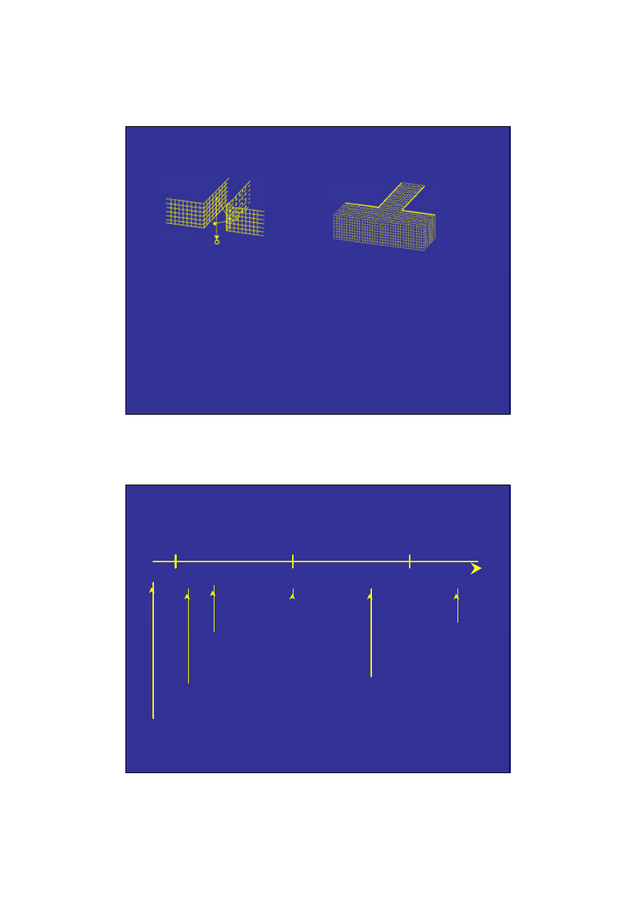
WAVE EQUATION SOLVING
The surface or the volume is divided into elements.
• The elements must be much smaller than
λ
⇒
Computational load for FDTD/FEM
∝
f
3
/ f
4
!
• All details must be modeled
• Source directivity is tricky with FEM/FDTD
R
S
BEM
FEM,
FDTD/DWG
COMPUTER MODELLING IN
ROOM ACOUSTICS - SOME
MILESTONES
1970 1980 1990
Ray tracing - Krokstad et al
(specular & diffuse)
Radiosity - Kuttruff
(only diffuse)
Image Source Method -
Juricic & Santon
(only specular)
Beam Tracing - Walsh et al
(specular + diffraction)
Time BEM -
Dohner et al
Hybrid method -
van Maercke
FDTD/DWG -
Botteldooren/
Savioja

5
COMPUTER MODELLING IN
ROOM ACOUSTICS - SOME
MILESTONES
1980 1990 2000
CATT-Acoustic,
Odeon, EASE
Ramsete
Software:
Other:
Bose Modeler
Raynoise
Epidaure
Ulysses
…
Round-Robin 1
- Vorländer
Round-Robin 2&3
- Bork
Systematic
evaluation:
RELATED FIELDS
Accurate
room
modeling
Loudspeaker system
modeling
Virtual
reality
Music
processing
Outdoor sound
propagation
Building
acoustics
(sound insulation)
Small rooms
(e.g., car cabins)
Industrial
buildings
(e.g., factories)

6
METHODS, 1
√
BEM
√
FEM
√
ISM + Ray/cone
tracing
Noise control
(small
rooms)
Room acoustics,
factories,
loudsp. systems
Sofar, mainly in research:
Beam tracing, Radiosity, ISM + Edge
diffraction, FDTD
METHODS, 2
FEM, BEM, FDTD
Comp. load grows very fast with
frequency (f
3
/ f
4
).
All details must be modeled!
FEM, FDTD
Source directivity tricky.
ISM + Ray/cone
Does not (yet) handle diffraction
tracing
Beam tracing
Does not (yet) handle scattering.
Radiosity
Does not (yet) handle diffraction.
Do not handle spherical reflection from
absorbers (or seat-dip effect)
7
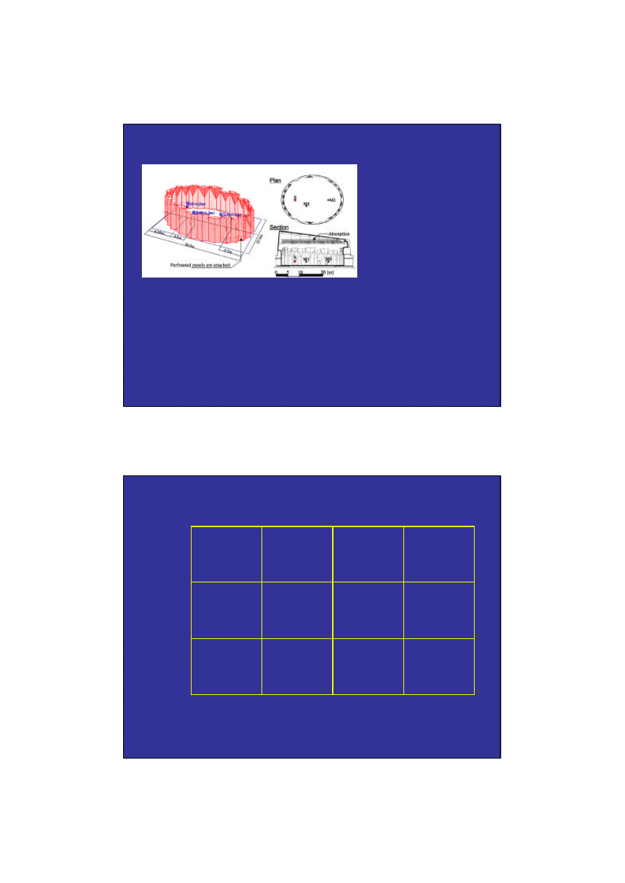
STATE-OF-THE-ART FDTD, 1
At ICA 2004, Sakamoto (Tokyo University) demonstrated
an FDTD calculation of a small concert hall (˜ 5000 m3)
up to 1.4 kHz. The model had >100 million elements, ran
on 8 PCs with 11 GB for 34 hours.
(From Sakamoto
et al, ICA 2004)
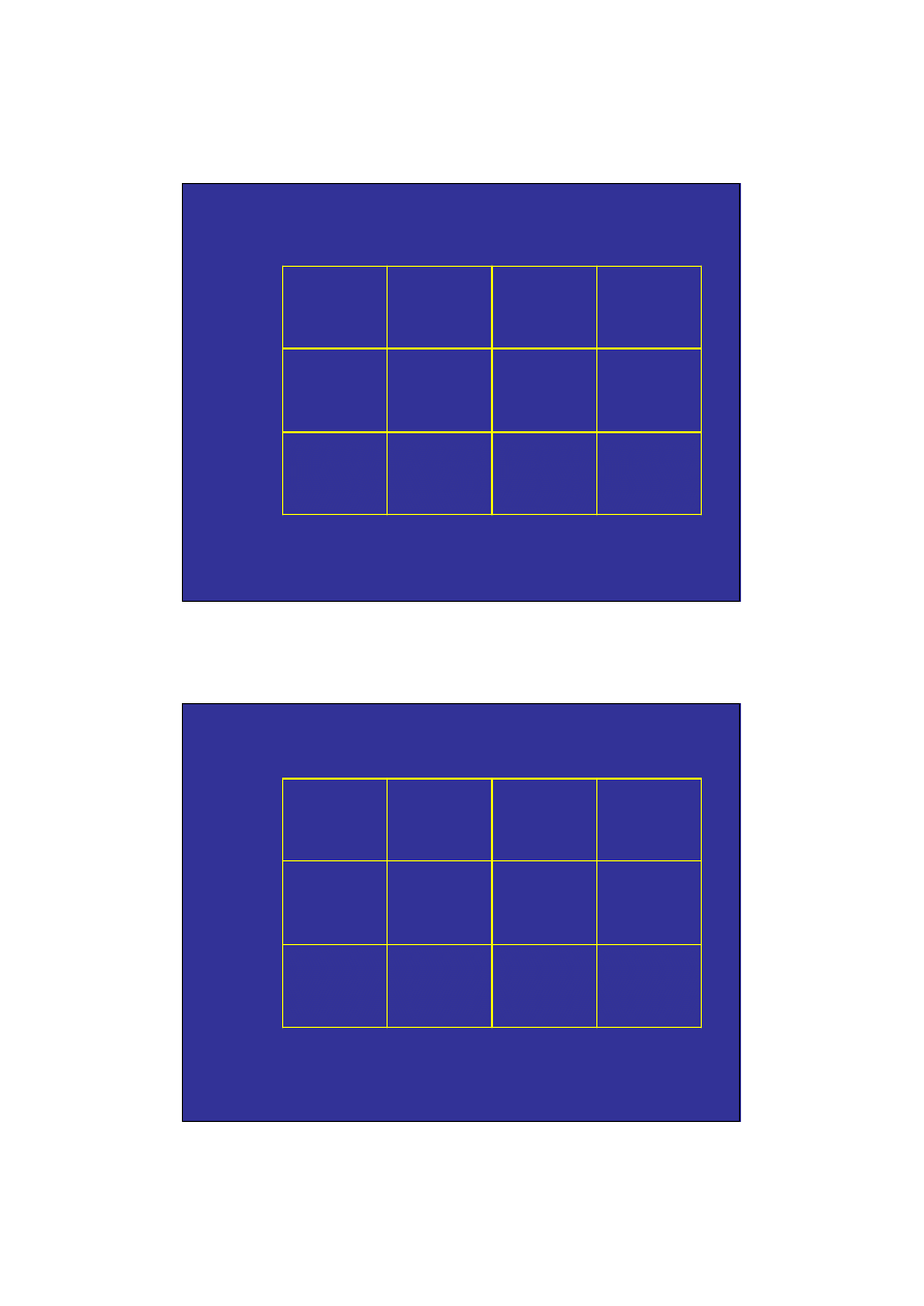
STATE-OF-THE-ART FDTD, 2
10 GB
1 day
1 kHz 2 kHz 4 kHz 8 kHz
5000 m
3
40000 m
3
160000 m
3
8
STATE-OF-THE-ART FDTD, 2
80 GB
2 days
80 GB
16 days
10 GB
1 day
1 kHz 2 kHz 4 kHz 8 kHz
5000 m
3
40000 m
3
160000 m
3
STATE-OF-THE-ART FDTD, 2
640 GB
4 days
640 GB
32 days
80 GB
2 days
640 GB
256 days
80 GB
16 days
10 GB
1 day
1 kHz 2 kHz 4 kHz 8 kHz
5000 m
3
40000 m
3
160000 m
3

9
STATE-OF-THE-ART FDTD, 2
300 TB
44 yrs
4.8 TB
64 days
640 GB
4 days
4.8 TB
512 days
640 GB
32 days
80 GB
2 days
4.8 TB
11 yrs
640 GB
256 days
80 GB
16 days
10 GB
1 day
1 kHz 2 kHz 4 kHz 8 kHz
5000 m
3
40000 m
3
160000 m
3
STATE-OF-THE-ART FDTD, 2
300 TB
44 yrs
4.8 TB
64 days
640 GB
4 days
4.8 TB
512 days
640 GB
32 days
80 GB
2 days
4.8 TB
11 yrs
640 GB
256 days
80 GB
16 days
10 GB
1 day
1 kHz 2 kHz 4 kHz 8 kHz
But, next time BNAM is in Finland, computers
are maybe 100 times faster, so 0.4 years instead
of 44 years!
5000 m
3
40000 m
3
160000 m
3
10
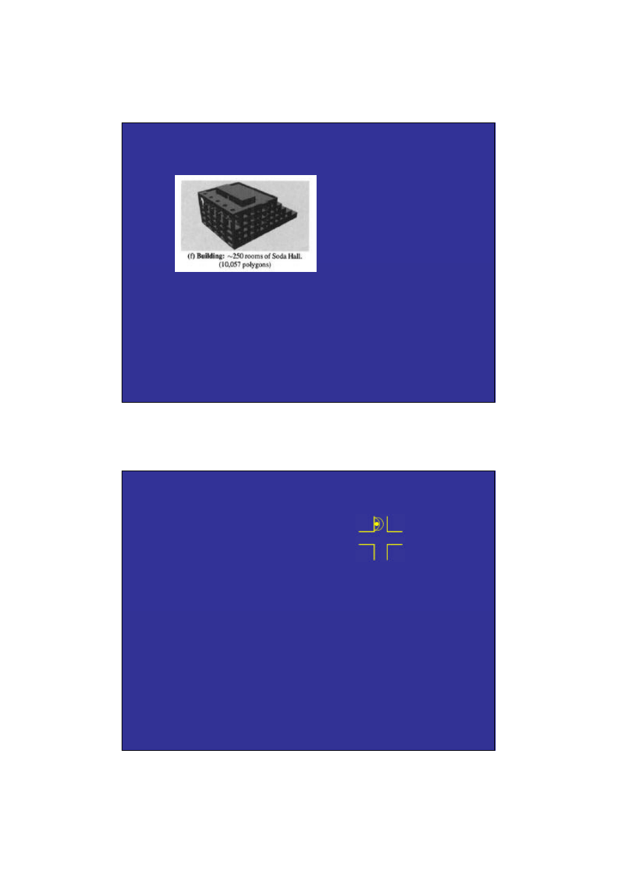
STATE-OF-THE-ART BEAM
TRACING
Beam tracing implements eighth order specular reflection
in a 10 000 plane model: 190 seconds preprocessing +
49 seconds, using 19 MB of memory on a PC.
(From Funkhouser
et al, JASA 2004)
Note! Only specular reflections - no scattering, no edge
diffraction (but edge diffraction has been demonstrated).
EXAMPLE, EDGE
DIFFRACTION
Streetcorner, omni-
directional sound source
Only specular
reflections
Specular reflections
and edge diffraction
QuickTime™ and a
MPEG-4 Video decompressor
are needed to see this picture.
QuickTime™ and a
MPEG-4 Video decompressor
are needed to see this picture.
Specular reflections give truncated wavefronts, which
is clearly wrong. The inclusion of edge diffraction can
be more or less important in rooms.
11
THE INPUT DATA
PROBLEM
Absorption
Now: 125 Hz - 4 kHz
Scattering
ISO scattering coefficient is coming
Scattering
Scattering function
Source directivity
We need shared and standardized data sets!
Advanced methods can never give better
output data than the quality of the input data!!
ROUND ROBIN I,
VORLÄNDER 1995
Auditorium at PTB
Only 1kHz band
14 different softwares
Findings:
• Specular + diffuse reflections needed for rev. tail
• 3 softwares were judged very reliable - within 1-2
JND for most parameters
• Importance of right input data
12
ROUND ROBIN II, BORK 2000
Concert hall, Elmia
125 Hz - 4 kHz bands
16 participants
Findings:
• Most parameters and softwares had similar accuracy
• Problems in 125 Hz band - diffraction or seat-dip
effect not modeled by any software
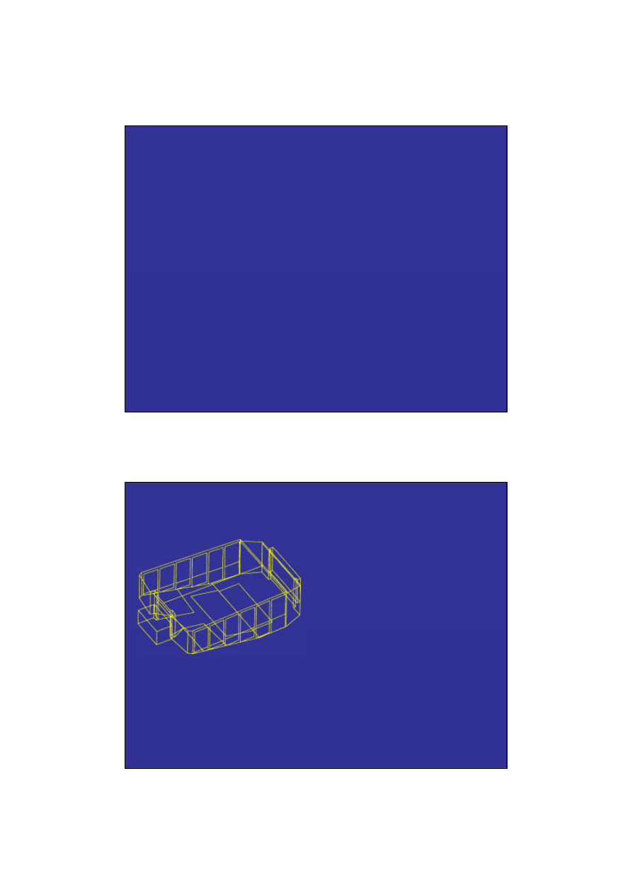
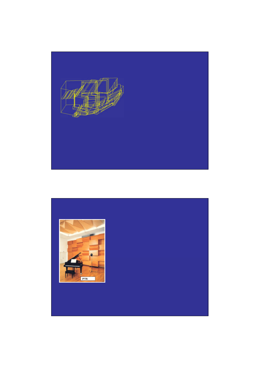
ROUND ROBIN III, BORK 2002
(From Bork 2002)
Studio at PTB
125 Hz - 4 kHz bands
Findings:
• Uncertainties in measurement of
lateral parameter - microphone
problems
• Large deviations between
measurements and simulations
for 125 Hz.

13
THE ULTIMATE
METHOD?
Time
Frequency
BEM/FEM/FDTD/DWG
ISM
+ ED
Ray/cone tracing
or radiosity
We would have liked a single method
- but it does not seem feasible!
CONCLUSIONS
Computer modeling of rooms clearly mature, with ISM+Ray/cone
tracing, but still some phenomena to take care of:
• Seat-dip effect
• Diffraction
• Scattering data/functions
• Source directivity (multi-channel recordings?)
• Source or receiver near absorbing surfaces.
Input data, and standardized format needed: scattering data,
source directivity.
Benchmarking/Round Robins very important. Need to continue -
even for auralization. Very important to control “nuisance factors”
in comparisons.
Advanced methods need good input data!!!

14
REFERENCES
A. Krokstad, S. Strøm, S. Sørsdal, “Calculating the acoustical room response by the use of a ray
tracing technique,” J. Sound Vib. 8, pp. 118-125 (1968).
H. Kuttruff, “Simulierte nachhallkurven in rechteckräumen mit diffusem Schallfeld,” Acustica 25, pp.
333-342 (1971).
H. Juricic, F. Santon, “Images et rayons sonores dans le calcul numérique des échogrammes,”
Acustica 28, pp. 77-89 (1973).
J. P. Walsh, “The Design of Godot: A System for Computer-Aided Room Acoustics Modeling and
Simulation,” Proc. of ICA, (1980).
J. L. Dohner, R. Shoureshi, R. J. Bernhard, “Transient analysis of three-dimensional wave propagation
using the boundary element method,” Int. J. for Num. Methods in Eng. 24, pp. 621-634 (1987).
D. Botteldooren, “Acoustical finite-difference time-domain simulation in a quasi-cartesian grid,” J.
Acoust. Soc. Am. 95, pp. 2313-2319 (1994).
L. Savioja, T. Rinne, T. Takala, “Simulation of room acoustics with a 3-D finite difference mesh,” in
Proc. Int. Computer Music Conf., (Aarhus, Denmark), pp. 463-466, (1994).
D. van Maercke, “Simulation of sound fields in time and frequency domain using a geometrical
model,” Proc. 12th Int. Cong. Acoust., Toronto, E11-7 (1986).
REFERENCES
M. R. Schroeder, “Digital simulation of sound transmission in reverberant spaces,” J. Acoust. Soc. Am.
47, pp. 424-
M. Vorländer, “International round robin on room acoustical computer simulations,” Proc. of the 15th
ICA, Trondheim , pp. 689-692 (1995).
I. Bork, “A comparison of room simulation software – The 2nd Round Robin on room acoustical
computer simulation,” Acustica/Acta Acustica 86, pp. 943-956 (2000).
I. Bork, “Simulation and measurement of auditorium acoustics - The round robins on room acoutical
simulation,” Proc. of the IOA 24, Pt4. (2002).
S. Sakamoto, T. Yokota, H. Tachibana, “Numerical sound field analysis in halls using the finite
difference time domain method,” Proc. of RADS 2004, Awaji, Japan, (2004).
T. Funkhouser, N. Tsingos, I. Carlbom, G. Elko, M. Sondhi, J. E. West, G. Pingali, P. Min, A. Ngan, “A
beam tracing method for interactive architectural acoustics,” JASA 115, pp. 739-756 (2004).
Wyszukiwarka
Podobne podstrony:
Claus Lynge Christensen Modelling Large Sound Sources in a Room Acoustical
Iannace, Ianniello, Romano Room Acoustic Conditions Of Performers In An Old Opera House
Nijs L , de Vries The young architect’s guide to room acoustics
IMPORTANCE OF EARLY ENERGY IN ROOM ACOUSTICS
Katz International Round Robin on Room Acoustical
Michael Vorlander Internationa Round Robin on Room Acoustical Computer Simulations
Munster B , Prinssen W Acoustic Enhancement Systems – Design Approach And Evaluation Of Room Acoust
Room Acoustics Acoustical Parameters Measurement
AJA Results of the NPL Study into Comparative Room Acoustic Measurement Techniques Part 1, Reverber
ROOM ACOUSTIC SIMULATION AND AURALIZATION – WESPAC8
AES Information Document For Room Acoustics And Sound Reinforcement Systems Loudspeaker Modeling An
New possibilities in room acoustics measuring
Nijs L , de Vries The young architect’s guide to room acoustics
Predicting Room Acoustical Behaviour with the ODEON
Dance, Shield Modelling of sound ®elds in enclosed spaces with absorbent room surfaces
Gardner The Virtual Acoustic Room
Dance, Shield Modelling of sound ®elds in enclosed spaces with absorbent room surfaces
Rindel MODELLING IN AUDITORIUM ACOUSTICS Sevilla 2002 Rindel 8p
więcej podobnych podstron