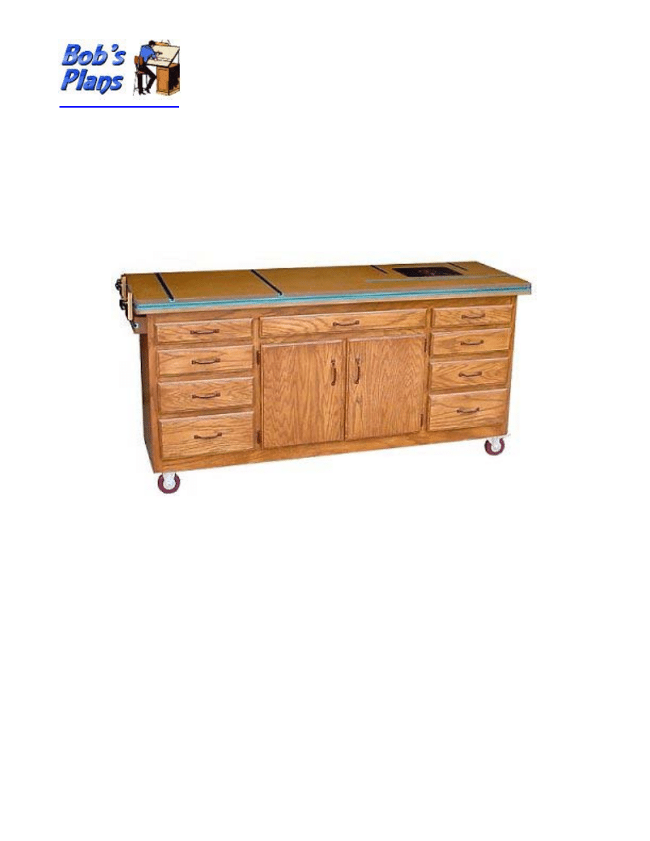
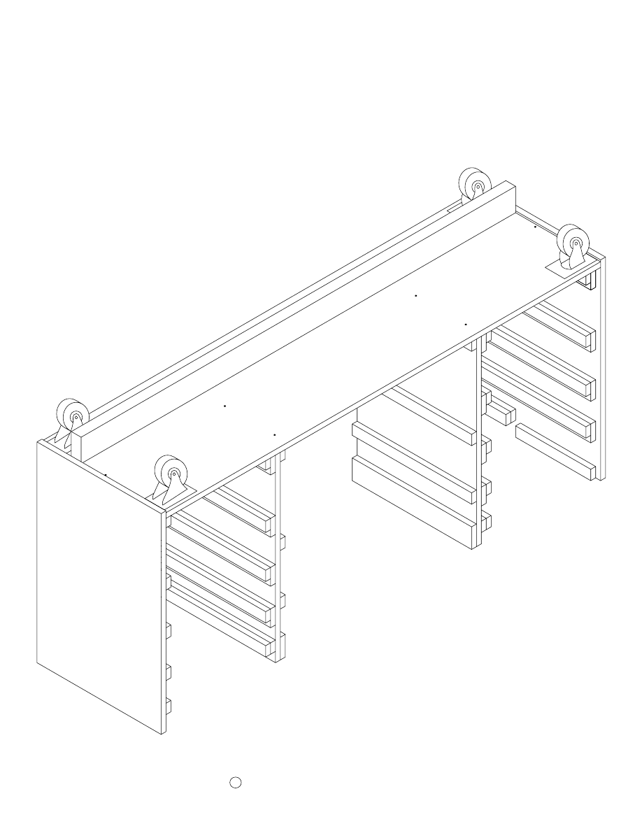
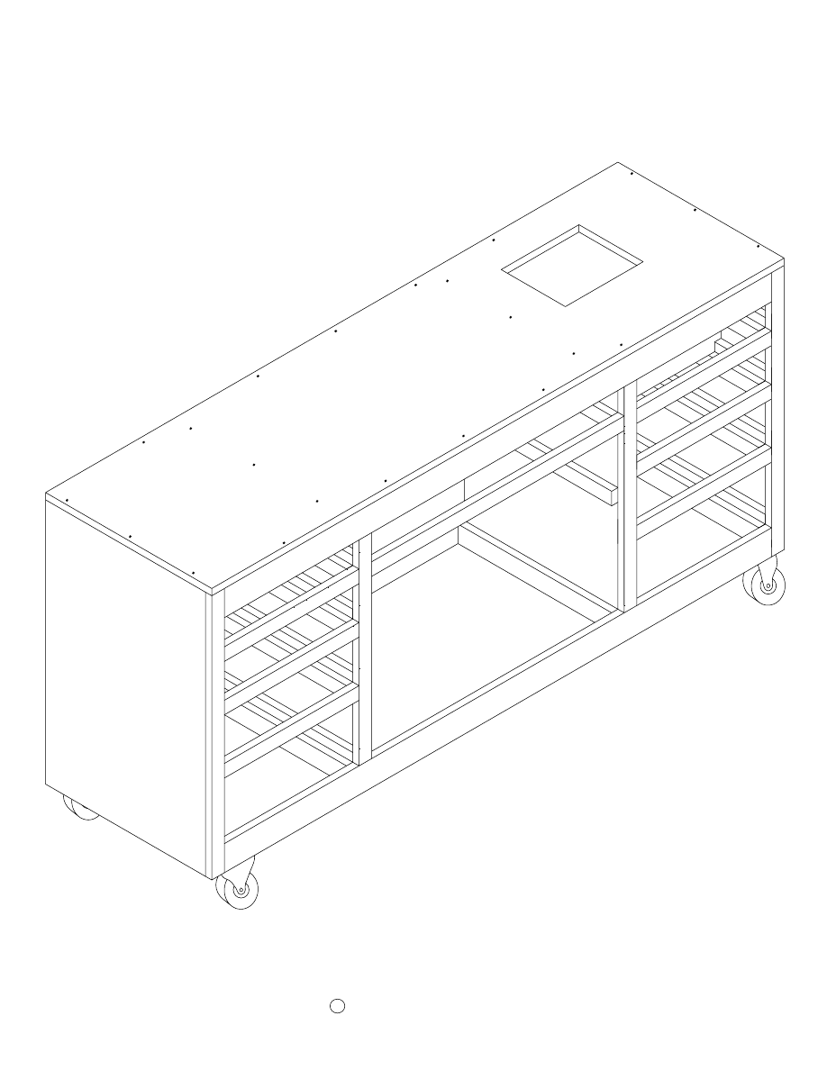
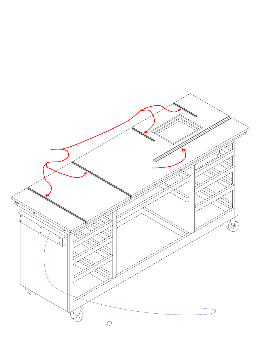
Garage Workbench Plans
Every home woodworker knows the importance of making efficient use of the available space in his or
her shop. This workbench is designed to provide the maximum functionality using the minimum
amount of space possible. It provides a work surface of about six feet by two feet and is about 35” in
height. Just the right size to provide ample work space for most projects.
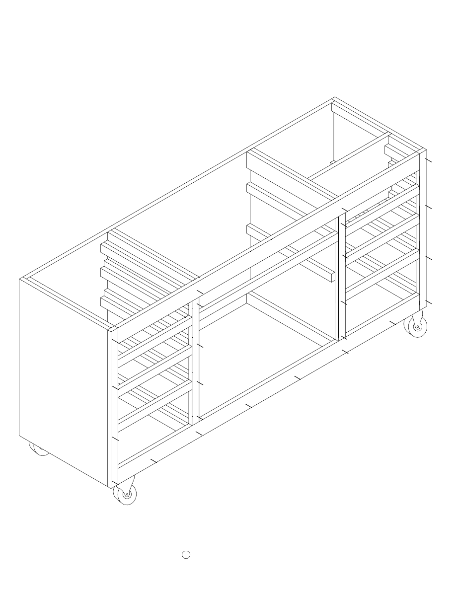
The features that make this workbench ideal for the home shop are the built in clamping system, the
built in router table, the nine drawers, the center cabinet space, and the mobility. The four inch casters
enable you to easily roll it into position when needed and roll it aside when it is not in use.
The top surface is made of two layers of 3/4” MDF. This provides an extremely flat work surface and
since it is also a router table, a flat work surface is a must. The T-track inlaid in the top and around the
edges makes the entire work surface a versatile clamping system that easily clamps very small or very
large work pieces.
Copyright © 2006 by Robert E. Reedy
All Rights Reserved
This document may not be reproduced in whole or in part without the express written consent of the author.

Table of Contents - 1
Dimensions Drawings
Materials List - 1 ......................................................................................................x
Materials List - 2 ......................................................................................................x
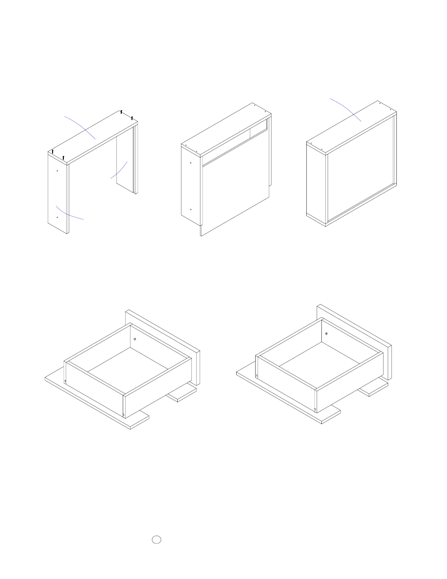
End and Center Panels ............................................................................................. 1
Base Dimensions & Layout ..................................................................................... 2
Back Dimensions & Layout .................................................................................... 3
Top Dimensions & Layout ...................................................................................... 4
Sub Top Dimensions & Layout .............................................................................. 5
Top Trim and T-Track ............................................................................................. 6
Drawer Slides, Stiffener, Misc. Small Parts ............................................................ 7
Drawer Fronts, Front Trim, and Doors ................................................................... 8
Drawer Boxes Dimensions ...................................................................................... 9
Router Bit Trays .................................................................................................... 10
Middle Shelf .......................................................................................................... 11

Table of Contents - 2
Assembly Instructions
Drawer Slides - Left Section - Left Panel ............................................................. 12
Drawer Slides - Left Section - Right Panel ........................................................... 13
Drawer Slides - Center Section - Left Panel ......................................................... 14
Drawer Slides - Center Section -Right Panel ........................................................ 15
Drawer Slides - Right Section - Left Panel ........................................................... 16
Drawer Slides - Right Section - Right Panel ......................................................... 17
Base to Panels ........................................................................................................ 18
Stiffener - Casters .................................................................................................. 19
Attach the Back ..................................................................................................... 20
Router Box Bottom & Shelf .................................................................................. 21
Router Box Front ................................................................................................... 22
Assemble the Face Frame ...................................................................................... 23
Attach the Face Frame ........................................................................................... 24
Attach the Leveling Blocks to the Panels .............................................................. 25
Attach the Front & Rear Leveling Blocks ............................................................. 26
Attach the Sub Top ................................................................................................ 27
Attach the Inner Trim ............................................................................................ 28
Attach the Middle Trim ......................................................................................... 29
Attach the Top ....................................................................................................... 30
Attach the Track to the Top ................................................................................... 31
Attach the Track to the Front & Ends ................................................................... 32
Attach the Lower Trim .......................................................................................... 33
Assemble the Drawer Boxes & Fronts .................................................................. 34
Assemble the Router Trays ................................................................................... 35
Attach Cabinet Doors ............................................................................................ 36
Attach Middle Door trim ....................................................................................... 37
Clamping System Parts ......................................................................................... 38
Assemble the EZ Mount Stop ............................................................................... 39
Clamping System Usage Instructions .................................................................... 40
Clamping System Illustrations .............................................................................. 41
Snapshots ............................................................................................................... 42
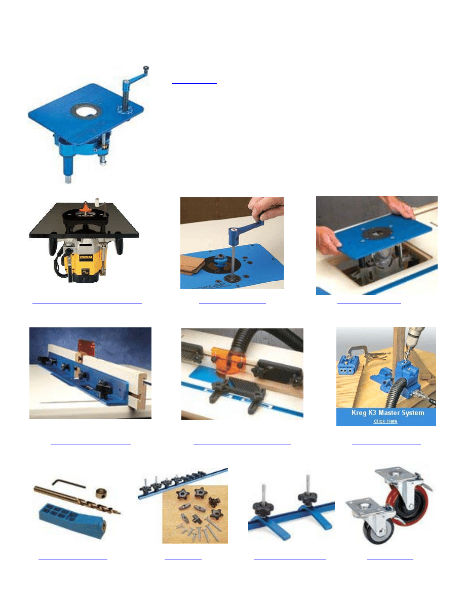
Tools and Accessories You’ll Need
Note: Images and underlined text are active web links.
Low Cost Lift for Plunge Routers
is precision-engineered to within .002" tolerance
and CNC-machined from 1" solid aluminum to eliminate bend-
ing and sagging.
Built-in insert adjusters allow for snugging the lift in your table
for a perfect fit, while the built-in leveling system will not wear
into the table's recessed opening
Plate measures 9-1/4" x 11-3/4" x 3/8". Adjustments are made
with a drop-in speed handle that's elevated from the table.

Materials List - 1
Qty
Size
Material
Item name
2
29 1/4” by 19”
3/4” Oak Plywood
End Panels
2
28 1/4” by 18 1/4”
3/4” Plywood
Middle Panels
1
66 1/2” by 19”
3/4” Plywood
Base
1
66 1/2” by 28 1/4”
3/4” Plywood
Back
1
72” by 24”
3/4” MDF Board
Top
1
68” by 19 3/4”
3/4” MDF Board
Sub Top
2
69 1/2” by 1 1/2”
3/4” Wood or Plywood
1st Front & Back Sub Top Trim
2
21 1/4” ” by 1 1/2”
3/4” Wood or Plywood
1st End Sub Top Trim
2
71” by 1 1/2”
3/4” Wood or Plywood
2nd Front & Back Sub Top Trim
2
22 3/4” by 1 1/2”
3/4” Wood or Plywood
2nd End Sub Top Trim
2
36”
1/2” by 3/4” T-Track
Front T-Track
5
24”
1/2” by 3/4” T-Track
End & Top T-Track
1
72” by 3/4” by 1/2”
1/2” Thick MDF or Wood
Front Lower T-Track Trim
2
24” by 3/4” by 1/2”
1/2” Thick MDF or Wood
End Lower T-Track Trim
17
18 1/4” by 1 1/2”
3/4” Wood
Drawer Supports
5
6” by 1 1/2”
3/4” Wood
Small Drawer Supports
10
18 1/4” by 2 1/2”
3/4” Wood
Drawer Side Guides
2
6” by 2 1/2”
3/4” Wood
Small Drawer Side Guides
4
18 1/4” by 3”
3/4” Wood
Lower Drawer Side Guides
6
18 1/4” by 2”
3/4” Wood
Lower Drawer Supports
2
14 1/2” by 2”
3/4” Wood
Lower Back Supports
1
27 1/2” by 2”
3/4” Wood
Center Lower Back Support
4
17 1/2” by 1 1/2”
3/4” Wood
17 1/2” Leveling Block
3
16 3/4” by 1 1/2”
3/4” Wood
16 3/4” Leveling Block
2
30” by 1 1/2”
3/4” Wood
30” Leveling Block
1
10 1/4” by 1 1/2”
3/4” Wood
10 1/4” Leveling Block
1
66 1/2”
2 by 4 (3 1/2” by 1 1/2”)
Stiffener
6
16” by 1 1/2”
3/4” thick wood or plywood
Drawer Trim
2
29 1/4” by 1 1/2”
3/4” thick wood or plywood
Vertical End Trim
1
30” by 1 1/2”
3/4” thick wood or plywood
Middel Trim
x

Materials List - 2
Qty
Size
Material
Item name
2
23 1/4” by 1 1/2”
3/4” thick wood or plywood
Vertical Divider Trim
2
65” by 3”
3/4” thick wood or plywood
Upper & Lower Trim
1
3 1/2” by 30 1/2”
3/4” thick wood or plywood
Center Drawer Front
2
3 1/2” by 16 1/2”
3/4” thick wood or plywood
Top Drawer Front
2
4 1/2” by 16 1/2”
3/4” thick wood or plywood
4 1/2” Drawer Front
2
5 1/4” by 16 1/2”
3/4” thick wood or plywood
5 1/4” Drawer Front
2
7” by 16 1/2”
3/4” thick wood or plywood
7” Drawer Front
2
19” by 14 3/4”
3/4” thick wood or plywood
Cabinet Doors
1
3/4” thick wood or plywood
Door Lip
1
17 1/2” by 11 1/2”
3/4” thick wood or plywood
Router Box Front
6
19” by 2 7/8”
3/4” thick wood or plywood
Top Drawer Sides
4
19” by 3 7/8”
3/4” thick wood or plywood
3 7/8” Drawer Sides
4
19” by 4 7/8”
3/4” thick wood or plywood
4 7/8” Drawer Sides
4
19” by 6 5/8”
3/4” thick wood or plywood
6 5/8” Drawer Sides
2
28 3/8” by 2 7/8”
3/4” thick wood or plywood
Center Drawer Ends
4
14 3/8” by 2 7/8”
3/4” thick wood or plywood
Top Drawer Ends
4
14 3/8” by 3 7/8”
3/4” thick wood or plywood
3 7/8” Drawer Ends
4
14 3/8” by 4 7/8”
3/4” thick wood or plywood
4 7/8” Drawer Ends
4
14 3/8” by 6 5/8”
3/4” thick wood or plywood
6 5/8” Drawer Ends
1
29 1/8” by 18 1/4”
1/4” Hardboard
Center Drawer Bottom
6
15 1/8”” by 18 1/4”
1/4” Hardboard
Drawer Bottom
2
6” by 2 7/8”
3/4” thick wood or plywood
Top Router Tray Sides
2
6” by 3 7/8”
3/4” thick wood or plywood
2nd Router Bit Trays
2
14 7/8” by 6”
1/2” thick material
Router Bit Trays
2
14 7/8” by 6”
1/4” thick material
Router Bit Bottoms
1
18 1/4” by 30”
3/4” plywood
Middle Shelf
xi
28 1/4"
18 1/4"
Middle Panels
(2 Required)
29 1/4"
19"
End Panel
(2 Required)
End and Center Panels
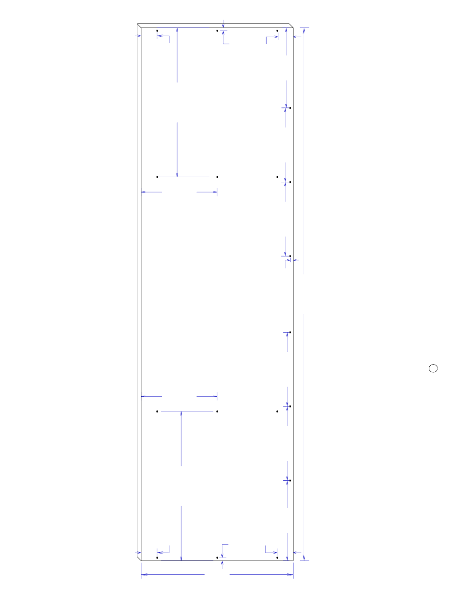
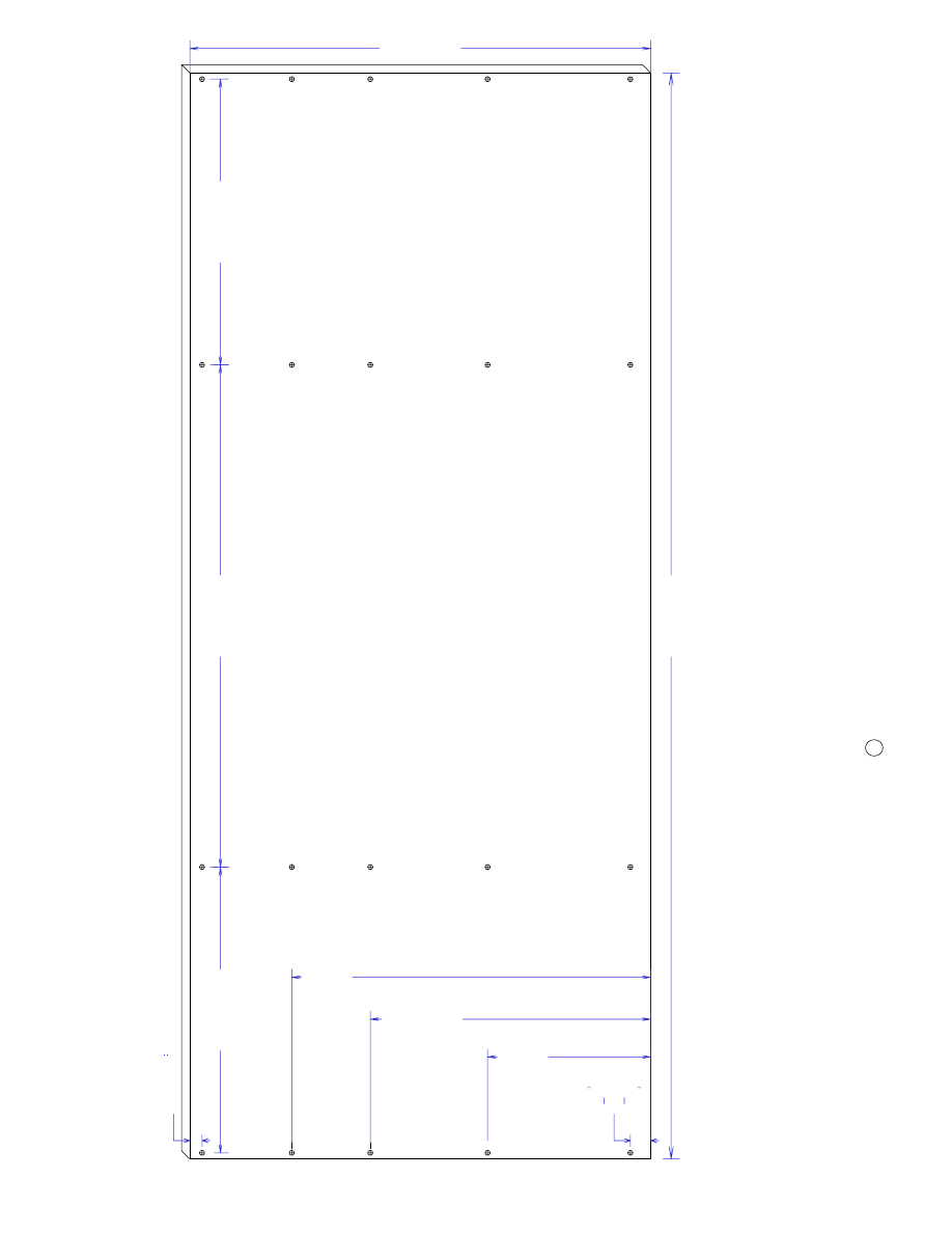
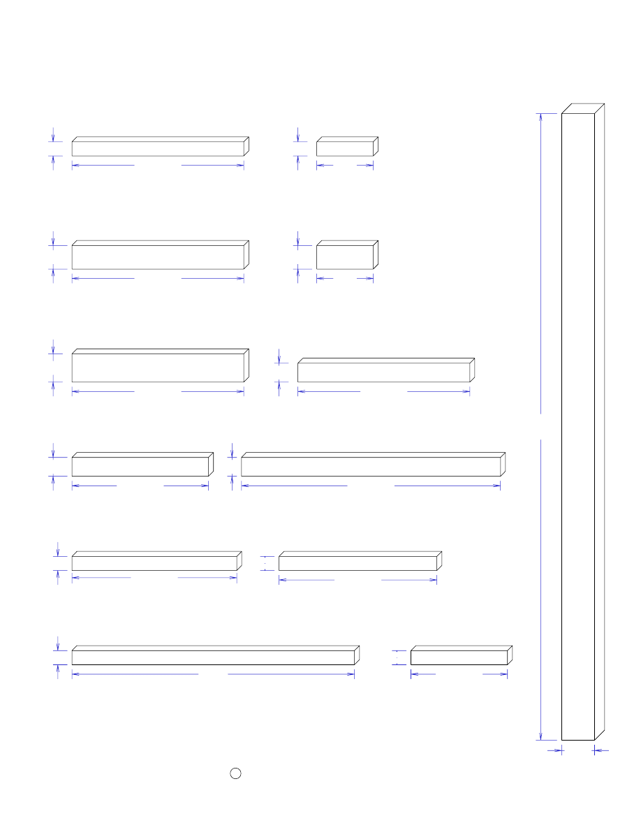
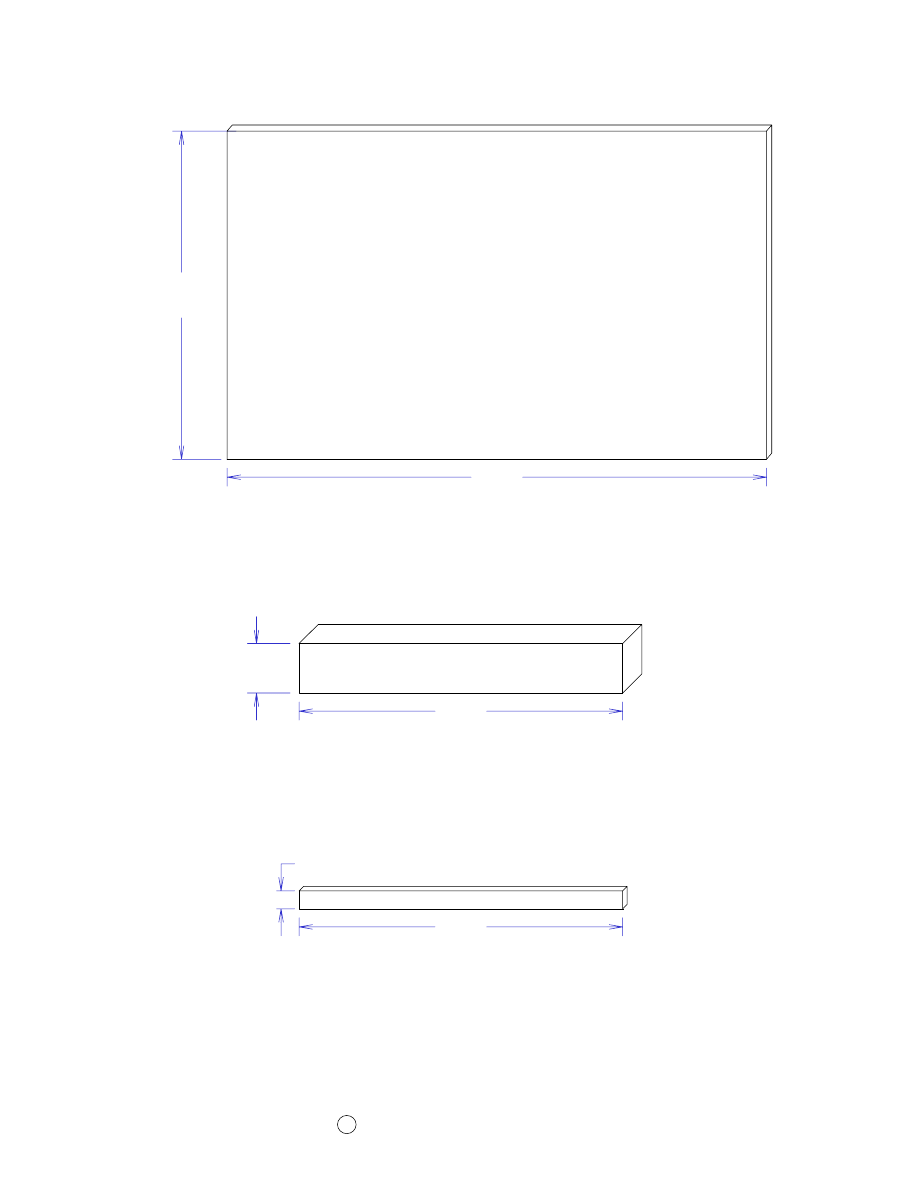
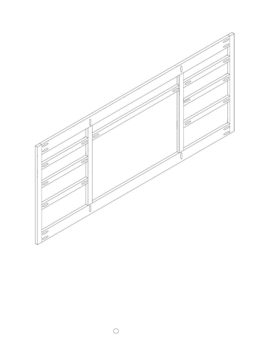
Page 1
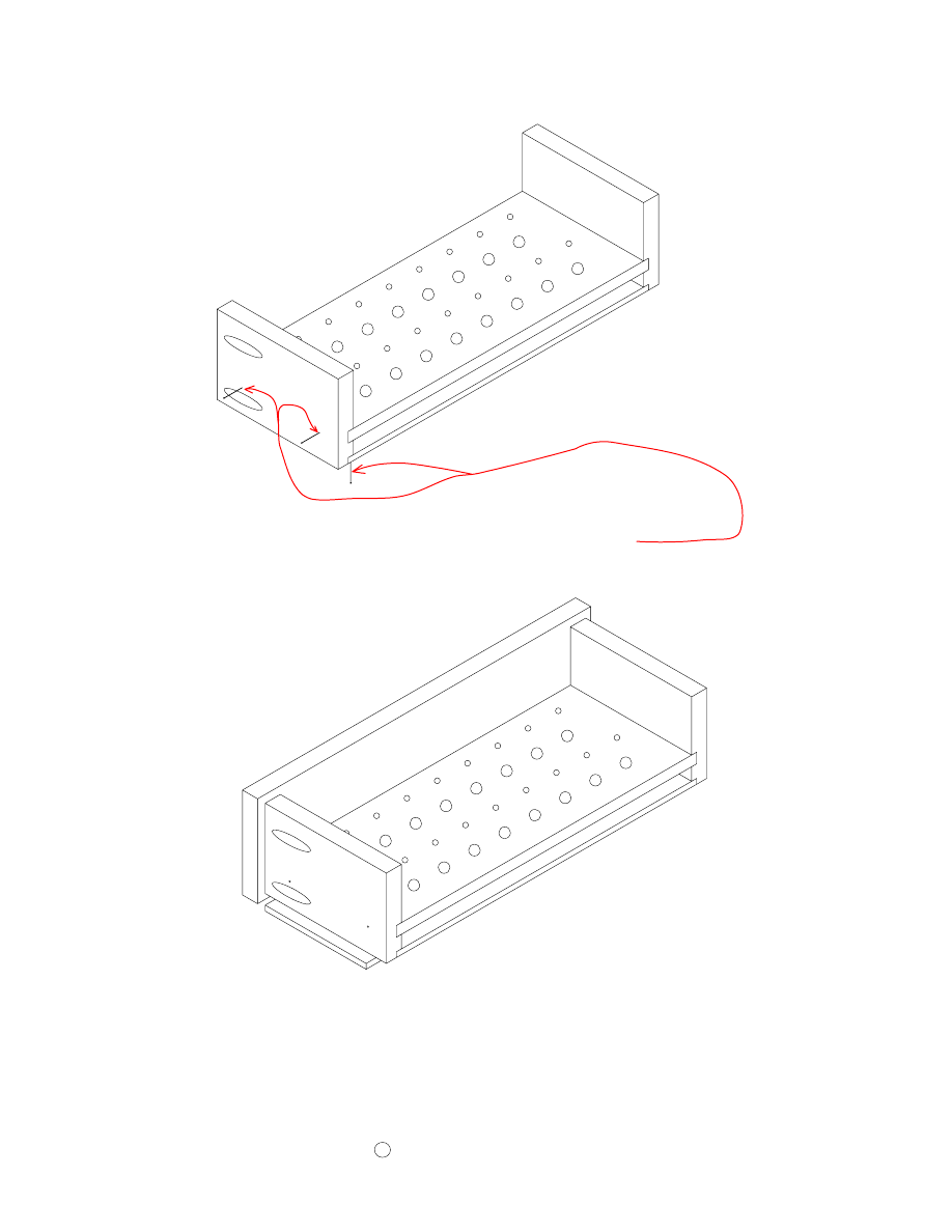
The two end panels are 1" taller than the center panels. This is because the
center panels sit on the top surface of the base and the end panels extend 1/4"
below the bottom surface of the base..
The end panels are also 3/4" wider than the center panels. This is so they will
be flush with the ends of the back section.
C
2006 by Robert E. Reedy, Vandalia, Ohio
Copyright
9 1/2"
9 1/2"
1
8
5
/8
"
19"
2
"
2
"
3
/8
"
2
"
3
/8
"
10"
9 1
/4
"
9 1/4
"
10"
9 1
/4
"
9 1/4"
3/8"
18
5/
8
"
2"
B
a
s
e
C
u
t
th
e
b
a
se
f
ro
m
3
/4
"
m
a
te
ri
a
l,
t
h
e
n
d
ri
ll
a
n
d
c
o
u
n
te
rs
in
k
h
o
le
s
fo
r
#
8
s
c
re
w
s
a
s
sh
o
w
n
i
n
th
e
d
ra
w
in
g
a
b
o
v
e
.
A
ll
t
h
e
s
c
re
w
s
a
ro
u
n
d
t
h
e
e
d
g
e
a
re
3
/8
"
fr
o
m
t
h
e
e
d
g
e
.
B
a
s
e
D
im
e
n
s
io
n
s
&
L
a
y
o
u
t
P
a
g
e
2
2
0
0
6
b
y
R
o
b
e
rt
E
.
R
e
e
d
y
,
V
a
n
d
a
lia
,
O
h
io
C
C
o
p
y
ri
g
h
t
66 1/2"
B
a
c
k
D
im
e
n
s
io
n
s
&
L
a
y
o
u
t
P
a
g
e
3
2
0
0
6
b
y
R
o
b
e
rt
E
.
R
e
e
d
y
,
V
a
n
d
a
lia
,
O
h
io
C
C
o
p
y
ri
g
h
t
B
a
c
k
1
7
1
/2
"
3
0
3
/4
"
1
7
1
/2
"
1 1/4"
3
/4
"
10"
17 1/8"
22"
28 1/4"
6
6
1
/2
"
C
u
t
th
e
b
ac
k
f
ro
m
3
/4
"
m
at
er
ia
l,
t
h
en
d
ri
ll
a
n
d
c
o
u
n
te
rs
in
k
h
o
le
s
fo
r
#
8
s
cr
ew
s
as
s
h
o
w
n
i
n
th
e
d
ra
w
in
g
a
b
o
v
e.
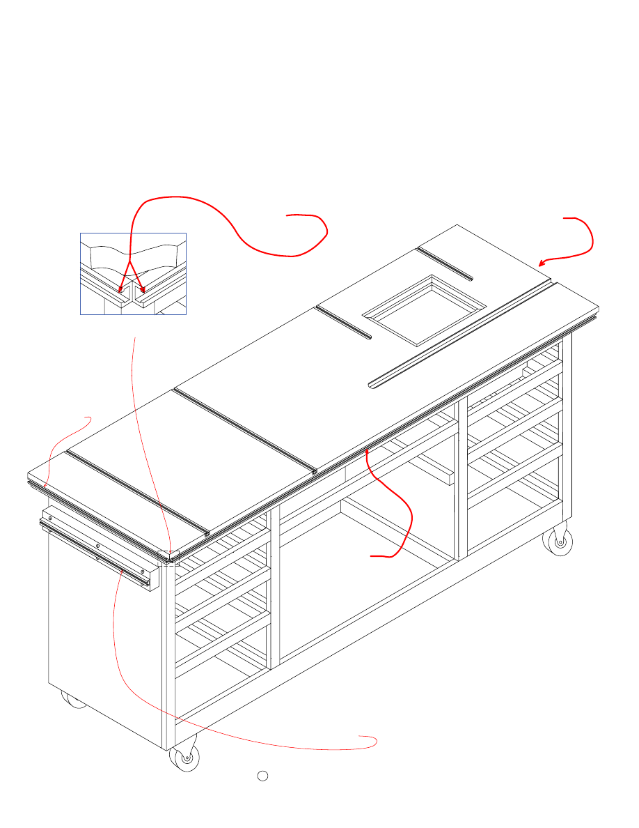
Top Dimensions and Layout
Page 4
Copyright
C
2006 by Robert E. Reedy, Vandalia, Ohio
T
h
is
d
ra
w
in
g
i
s
b
as
ed
o
n
a
9
1
/4
"
b
y
1
1
3
/4
"
ro
u
te
r
p
la
te
.
If
y
o
u
ar
e
u
si
n
g
a
d
if
fe
re
n
t
si
ze
p
la
te
,
y
o
u
w
il
l
n
ee
d
t
o
a
d
ju
st
t
h
e
si
ze
o
f
th
e
o
p
en
in
g
a
cc
o
rd
in
g
ly
.
T
h
e
ro
u
te
r
p
la
te
o
p
en
in
g
i
s
a
tw
o
s
te
p
p
ro
ce
ss
.
Y
o
u
m
u
st
c
u
t
an
i
n
n
er
o
p
en
in
g
t
h
at
l
ea
v
es
r
o
o
m
f
o
r
a
3
/4
"
w
id
e
li
p
a
ro
u
n
d
a
ll
f
o
u
r
ed
g
es
.
T
h
is
l
ip
i
s
w
h
at
t
h
e
ro
u
te
r
p
la
te
r
es
ts
u
p
o
n
.
F
ir
st
,
cu
t
th
e
in
n
er
o
p
en
in
g
c
o
m
p
le
te
ly
t
h
ro
u
g
h
t
h
e
to
p
.
If
y
o
u
'r
e
u
si
n
g
a
9
1
/4
"
b
y
1
1
3
/4
"
ro
u
te
r
p
la
te
,
th
is
i
n
n
er
o
p
en
in
g
s
h
o
u
ld
b
e
7
3
/4
"
b
y
1
0
1
/4
".
T
h
e
n
ex
t
st
ep
i
s
to
u
se
y
o
u
r
ro
u
te
r
to
c
re
at
e
th
e
li
p
a
ro
u
n
d
t
h
e
si
d
es
o
f
th
e
o
p
en
in
g
.
S
ee
t
h
e
d
et
ai
le
d
in
st
ru
ct
io
n
s
o
n
t
h
e
fo
ll
o
w
in
g
p
ag
e
fo
r
th
is
s
te
p
.
24"
72"
1
0
1
/8
"
1
0
1
/8
"
10 1/4"
7 3/4"
R
o
u
te
r
P
la
te
C
u
to
u
t
24"
7"
10"
6"
24"
F
e
n
c
e
T
-
T
ra
c
k
S
lo
t
T-Track & Miter Slot Cutout Dimensions
T
h
e
T
-T
ra
ck
a
n
d
m
it
er
g
au
g
e
sl
o
t
d
im
en
si
o
n
s
ar
e
b
as
ed
o
n
t
h
e
ce
n
te
r
o
f
th
e
sl
o
ts
.
H
o
w
ev
er
,
th
e
ex
ac
t
lo
ca
ti
o
n
o
f
th
es
e
it
em
s
is
st
ri
ct
ly
a
m
at
te
r
o
f
p
er
so
n
al
ch
o
ic
e.
30 1/2"
M
it
e
r
G
u
a
g
e
S
lo
t
If
y
o
u
w
il
l
b
e
u
si
n
g
a
re
ad
y
m
ad
e
ro
u
te
r
fe
n
ce
,
y
o
u
m
ay
n
ee
d
t
o
c
h
an
g
e
th
e
sp
ac
in
g
o
f
th
e
fe
n
ce
tr
ac
k
s
lo
ts
t
o
m
at
ch
y
o
u
r
fe
n
ce
.
T- Track Slot
T
-T
ra
ck
s
iz
es
v
ar
y
f
ro
m
b
ra
n
d
t
o
b
ra
n
d
.
T
h
e
m
o
st
c
o
m
m
o
n
s
iz
es
a
re
3
/4
"
w
id
e
b
y
1
/2
"
d
ee
p
o
r
3
/4
"
w
id
e
b
y
3
/8
"
d
ee
p
.
C
u
t
th
e
sl
o
ts
s
o
th
e
tr
ac
k
y
o
u
'r
e
u
si
n
g
i
s
fl
u
sh
w
it
h
t
h
e
to
p
su
rf
ac
e.
6 3/4"
17"
Sub Top Dimensions and Layout
Page 5
Drill and counter screwholes for #8 flathead screws in the locations shown below.
Copyright
C
2006 by Robert E. Reedy, Vandalia, Ohio
68"
19 3/4"
8"
R
o
u
te
r
B
o
x
C
u
to
u
t
18"
15 5/8"
N
o
te
:
T
h
is
d
ia
g
ra
m
i
s
b
a
s
e
d
o
n
a
9
1
/4
"
b
y
1
1
3
/4
"
ro
u
te
r
p
la
te
.
If
y
o
u
a
re
u
s
in
g
a
d
if
fe
re
n
t
s
iz
e
p
la
te
,
b
e
s
u
re
t
o
a
d
ju
s
t
th
e
o
p
e
n
in
g
s
iz
e
a
c
c
o
rd
in
g
ly
.
S
u
b
T
o
p
8 3/4"
10"
3
"
3
"
10"
3
"
3
"
3
"
3
"
1
1
/8
"
1
1
/8
"
1
1
/8
"
1
1
/8
"
S
u
b
T
o
p
S
c
re
w
H
o
le
L
a
y
o
u
t
S
c
re
w
H
o
le
L
a
y
o
u
t
R
o
u
te
r
B
o
x
C
u
to
u
t
19 3/8"
19 3/8"
14 5/8"
14 5/8"
9 1/2"
16"
26"
26"
16"
9 1/2"
2
0
0
6
b
y
R
o
b
e
rt
E
.
R
e
e
d
y
,
V
a
n
d
a
lia
,
O
h
io
C
C
o
p
y
ri
g
h
t
4
5
°
6
9
1
/2
"
4
5
°
1
s
t
F
ro
n
t
&
B
a
c
k
S
u
b
T
o
p
T
ri
m
(
2
R
e
q
u
ir
e
d
)
1 1/2"
T
h
e
S
u
b
T
o
p
t
ri
m
i
s
m
a
d
e
o
f
3
/4
"
th
ic
k
b
y
1
1
/2
"
h
ig
h
m
a
te
ri
a
l.
T
h
is
b
e
c
a
u
s
e
t
h
e
T
-T
ra
c
k
i
s
1
/2
"
b
y
3
/4
".
4
5
°
2
1
1
/4
"
4
5
°
1
s
t
E
n
d
S
u
b
T
o
p
T
ri
m
(
2
R
e
q
u
ir
e
d
)
1 1/2"
4
5
°
7
1
"
4
5
°
1 1/2"
2
n
d
F
ro
n
t
&
B
a
c
k
S
u
b
T
o
p
T
ri
m
(
2
R
e
q
u
ir
e
d
)
4
5
°
4
5
°
2
2
3
/4
"
1 1/2"
2
n
d
E
n
d
S
u
b
T
o
p
T
ri
m
(
2
R
e
q
u
ir
e
d
)
T
h
e
T
-T
ra
c
k
t
ri
m
i
s
m
a
d
e
o
f
1
/2
"
th
ic
k
b
y
3
/4
"
h
ig
h
m
a
te
ri
a
l.
T
h
is
b
e
c
a
u
s
e
t
h
e
T
-T
ra
c
k
i
s
1
/2
"
b
y
3
/4
".
3
/4
"
4
5
°
4
5
°
F
ro
n
t
T
-T
ra
c
k
T
ri
m
(
1
R
e
q
u
ir
e
d
)
7
2
"
3
/4
"
4
5
°
4
5
°
2
3
3
/4
"
E
n
d
T
-T
ra
c
k
T
ri
m
(
2
R
e
q
u
ir
e
d
)
3
5
1
/2
"
F
ro
n
t
T
-T
ra
c
k
(
2
R
e
q
u
ir
e
d
)
E
n
d
T
-T
ra
c
k
(
2
R
e
q
u
ir
e
d
)
23 1/4"
If
y
o
u
h
av
e
a
p
o
ck
et
h
o
le
j
ig
,
I
re
cc
o
m
m
en
d
d
ri
ll
in
g
p
o
ck
et
h
o
le
s
in
t
h
e
2
n
d
S
u
b
T
o
p
T
ri
m
p
ie
ce
s
as
s
h
o
w
n
.
T
h
es
e
p
o
ck
et
h
o
le
s
w
il
l
b
e
u
se
d
t
o
s
ec
u
re
t
h
e
T
o
p
t
o
t
h
e
S
u
b
T
o
p
.
T
h
e
ex
ac
t
lo
ca
ti
o
n
o
f
th
e
p
o
ck
et
h
o
le
s
is
n
o
t
cr
it
ic
al
.
T
h
e
im
p
o
rt
an
t
th
in
g
i
s
th
at
t
h
ey
d
o
n
o
t
li
n
e
u
p
w
it
h
t
h
e
sc
re
w
h
o
le
s
in
y
o
u
r
T
-T
ra
ck
.
If
y
o
u
d
o
n
o
t
h
av
e
a
p
o
ck
et
h
o
le
j
ig
,
th
e
T
o
p
c
an
b
e
se
cu
re
d
w
it
h
f
in
is
h
in
g
n
ai
ls
o
r
g
lu
e.
T
o
p
T
ri
m
&
T
-T
ra
c
k
P
a
g
e
6
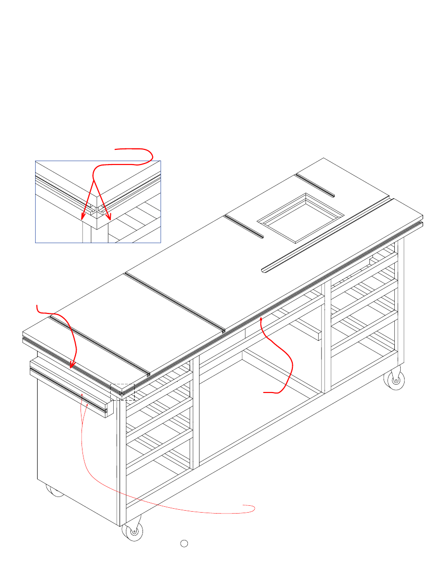
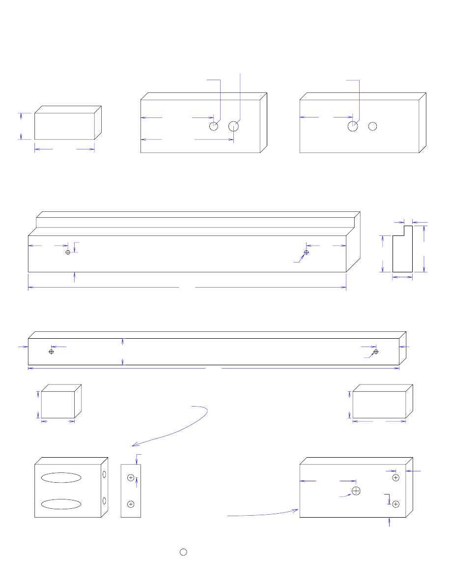
Center Lower Back Supports (1)
2"
27 1/2"
S
ti
ff
e
n
e
r
(M
a
k
e
t
h
e
s
ti
ff
e
n
e
r
fr
o
m
1
1
/2
"
th
ic
k
m
a
te
ri
a
l)
66 1/2"
3 1/2"
Copyright
C
2006 by Robert E. Reedy, Vandalia, Ohio
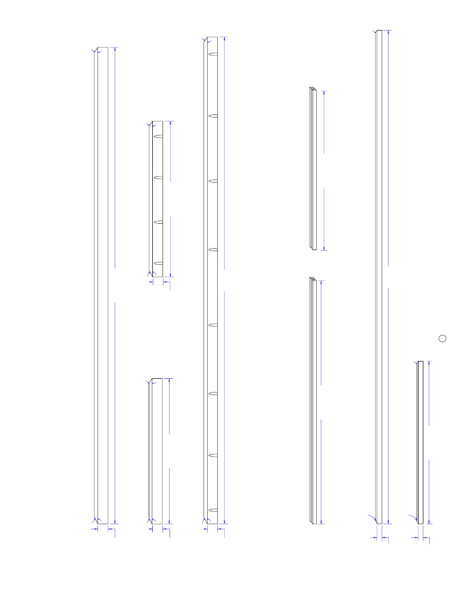
Drawer Slides / Stiffener / Misc Small Parts
18 1/4"
1 1/2"
Drawer Supports (17)
1 1/2"
6"
Small Drawer Supports (5)
2 1/2"
18 1/4"
Drawer Side Guides (10)
2 1/2"
6"
Small Drawer Side Guides (2)
18 1/4"
3"
Lower Drawer Side Guides (4)
2"
18 1/4"
Lower Drawer Supports (6)
Lower Back Supports (2)
2"
14 1/2"
1 1/2"
17 1/2"
17 1/2" Leveling Blocks (4)
16 3/4"
1 1/2"
16 3/4" Leveling Blocks (3)
30"
1 1/2"
30" Leveling Blocks (2)
1 1/2"
10 1/4" Leveling Block (1)
10 1/4"
Page 7
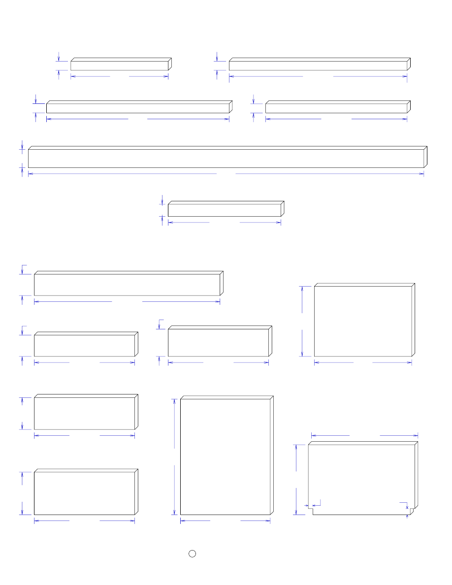
Drawer Fronts, Front Trim, and Doors
Copyright
C
2006 by Robert E. Reedy, Vandalia, Ohio
16 1/2"
7"
7" Drawer Fronts (2)
16 1/2"
5 1/4"
5 1/4" Drawer Fronts (2)
3 1/2"
Top Drawer Fronts (2)
16 1/2"
4 1/2" Drawer Fronts (2)
16 1/2"
4 1/2"
Cabinet Doors (2)
14 3/4"
19"
3 1/2"
30 1/2"
Center Drawer Front (1)
Router Box Bottom (1)
16"
11 1/2"
17 1/2"
11 1/2"
1"
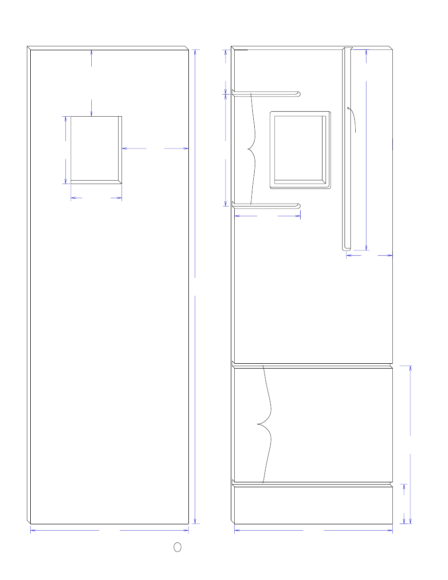
3/4"
Router Box Front (1)
Drawer Fronts Dimensions
Router Box Dimensions
Page 8
29 1/4"
1 1/2"
Vertical End Trim (2)
Drawer Trim (6)
1 1/2"
16"
Middle Trim (1)
1 1/2"
30"
23 1/4"
1 1/2"
Vertical Divider Trim (2)
Upper & Lower Trim (2)
65"
3"
18 1/2"
2"
Middle Door Trim (1)
2 7/8"
Center Drawer Ends (2)
28 3/8"
2 7/8"
14 3/8"
Top Drawer Ends (4)
14 3/8"
6 5/8"
6 5/8" Drawer Ends (4)
14 3/8"
3 7/8"
3 7/8" Drawer Ends (4)
14 3/8"
4 7/8"
4 7/8" Drawer Ends (4)
15 1/8"
Drawer Bottoms (6)
Center Drawer Bottom (1)
18 1/4"
29 1/8"
18 1/4"
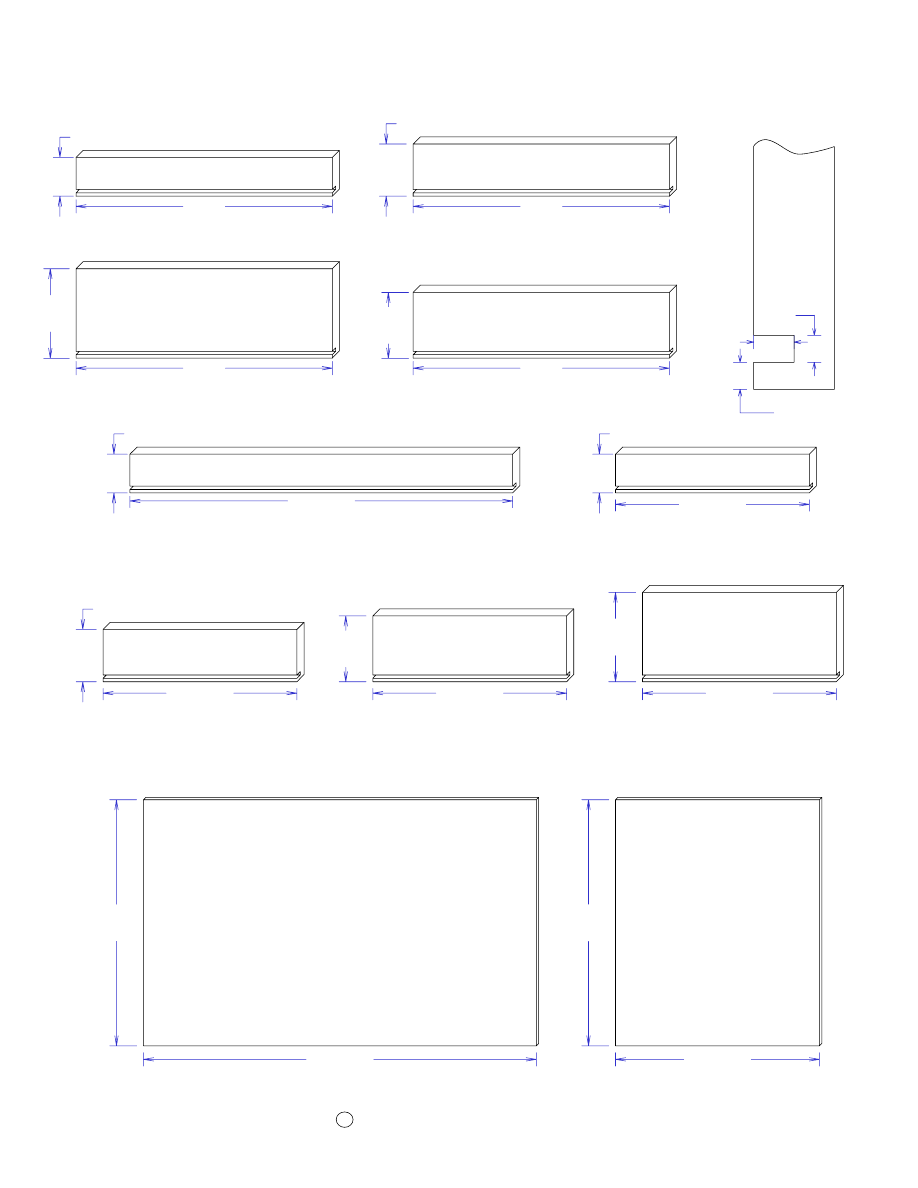
Drawer Boxes Dimensions
Page 9
C
2006 by Robert E. Reedy, Vandalia, Ohio
Copyright
Top Drawer Sides (6)
2 7/8"
19"
19"
6 5/8"
6 5/8" Drawer Sides (4)
3 7/8" Drawer Sides (4)
19"
3 7/8"
19"
4 7/8" Drawer Sides (4)
4 7/8"
1/4"
3/8"
1/4"
D
e
ta
il
V
ie
w
-
D
ra
w
e
r
B
o
tt
o
m
C
u
to
u
t
6"
2 7/8"
Top Router Tray Sides (2)
6"
3 7/8"
2nd Router Tray Sides (2)
3 7/8"
1 1/2"
1/4"
1/4"
1/2"
T
o
p
R
o
u
te
r
T
ra
y
S
id
e
s
(
E
n
d
V
ie
w
)
1/4"
1/2"
2 1/2"
3 7/8"
1/4"
2
n
d
R
o
u
te
r
T
ra
y
S
id
e
s
(
E
n
d
V
ie
w
)
The tray sides are made from 3/4" material. The heights of
the sides are 2 7/8" and 3 7/8" respectively. This provides
1/8" of top clearance in the drawer openings.
Cut 1/2" wide by 1/4" deep slots for the router trays in the sides as
shown. Then cut a 1/4" rabbit on the bottom of each side as shown. The
1/4" rabbits are for the bottoms. The bottoms are necessary so the router
bits cannot protude past the bottom of the drawer opening.
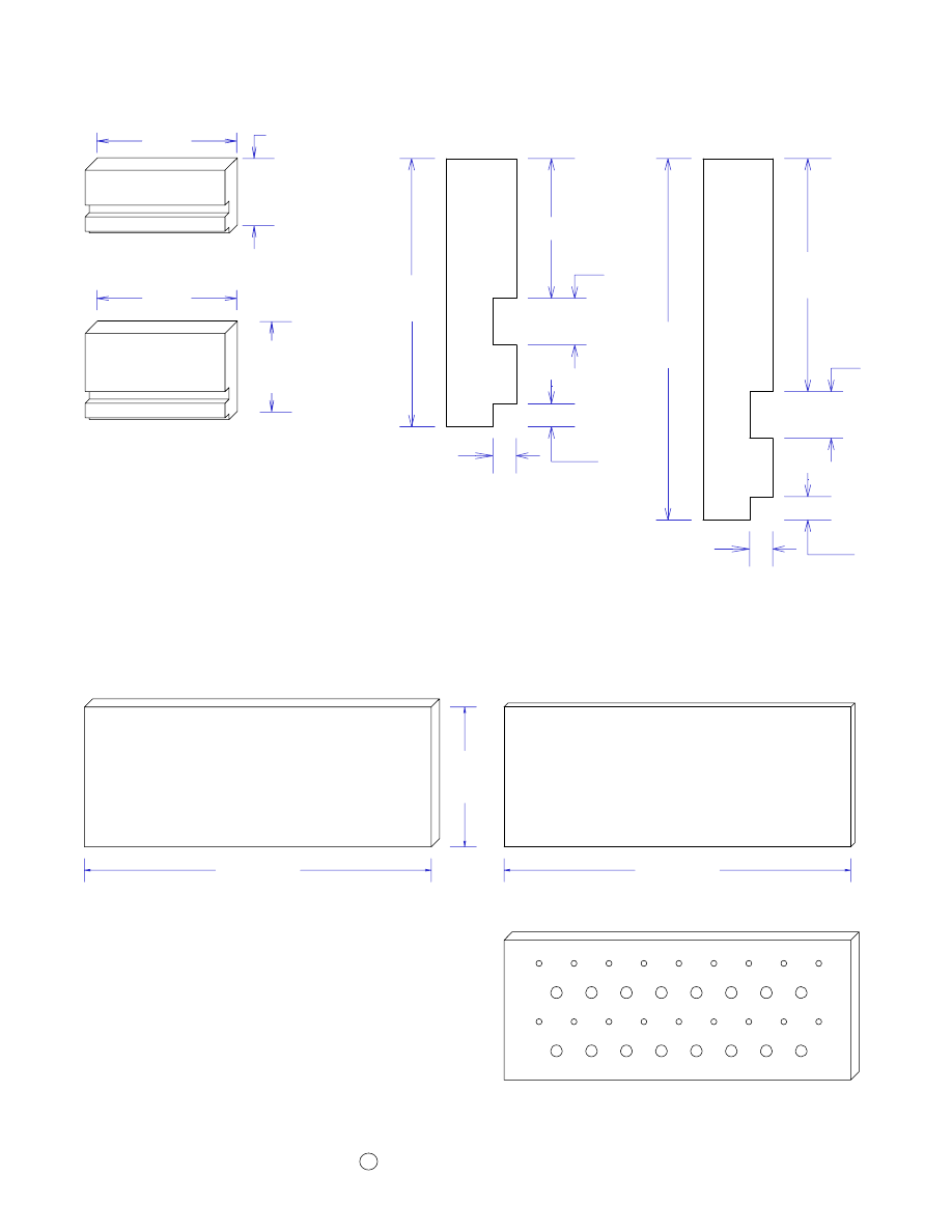
Router Bit Trays
Page 10
6"
14 7/8"
Cut two 6" by 14 7/8" router bits trays from
1/2" thick material and two bottoms from
1/4" thick material as shown above.
Drill several 1/4" and 1/2" holes for your
router bits in the 1/2" thick sections. The
exact location of the holes is strictly a matter
of preference. I put the holes about 1 1/2"
apart in the prototype.
Copyright
2006 by Robert E. Reedy, Vandalia, Ohio
C
14 7/8"
Router Bit Tray - Bottom (2)
1/4" thick material
Router Bit Tray (2)
1/2" thick material
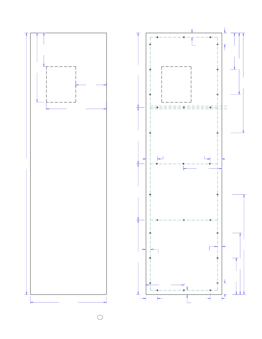
Middle Shelves Dimensions
Page 11
18 1/4"
Middle Shelf
30"
Copyright
2006 by Robert E. Reedy, Vandalia, Ohio
C
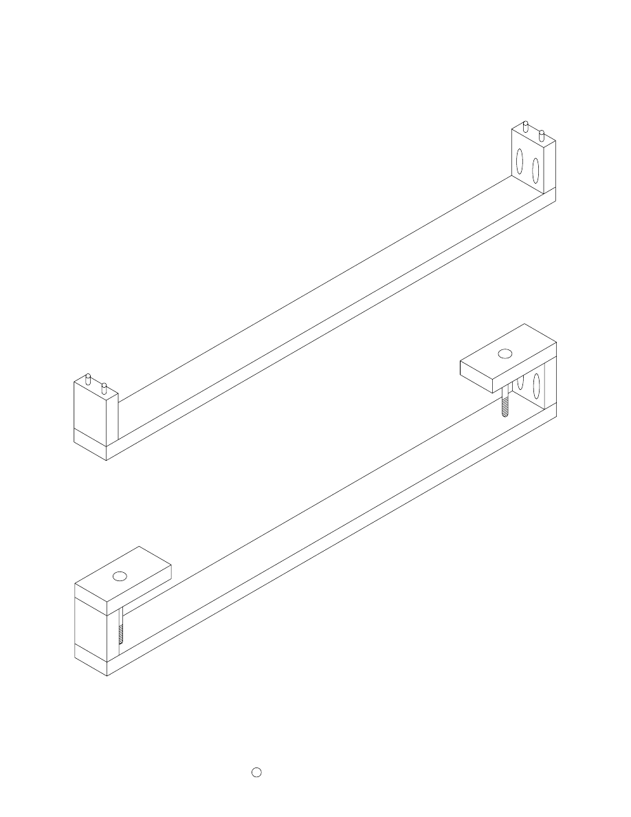
Lower Track Trim (2)
(Lower Track Trim is made of 1/2" thick material.)
18"
1"
18"
2 3/4"
Lower Track Support (2)
(Lower Track Support is made of 1 1/2" thick material.)
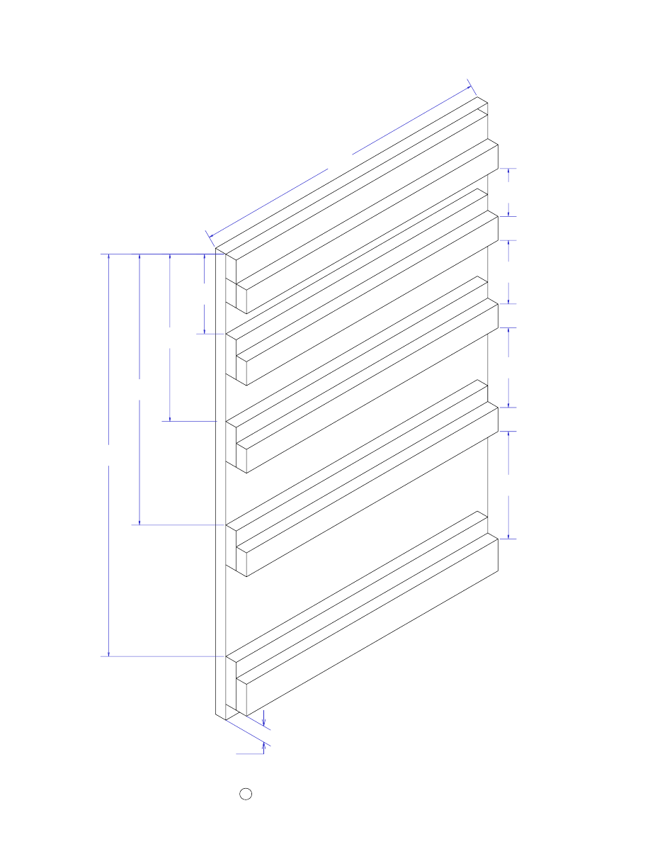
Attach Drawer Slides Left Section - Left Panel
Page 12
Copyright
2006 by Robert E. Reedy, Vandalia, Ohio
C
5"
17"
25 1/4"
19"
Le
ft E
nd
P
an
el
3"
4"
5"
6 3/4"
Dr
aw
er
Su
pp
ort
Dr
aw
er
Su
pp
ort
Lo
we
r D
raw
er
Su
pp
ort
Dr
aw
er
Su
pp
ort
Dr
aw
er
Sid
e G
uid
e
Dr
aw
er
Su
pp
ort
Le
ve
lin
g B
loc
k
1"
Lo
we
r D
raw
er
Sid
e G
uid
e
Dr
aw
er
Sid
e G
uid
e
Dr
aw
er
Sid
e G
uid
e
10 1/2"
Page 13
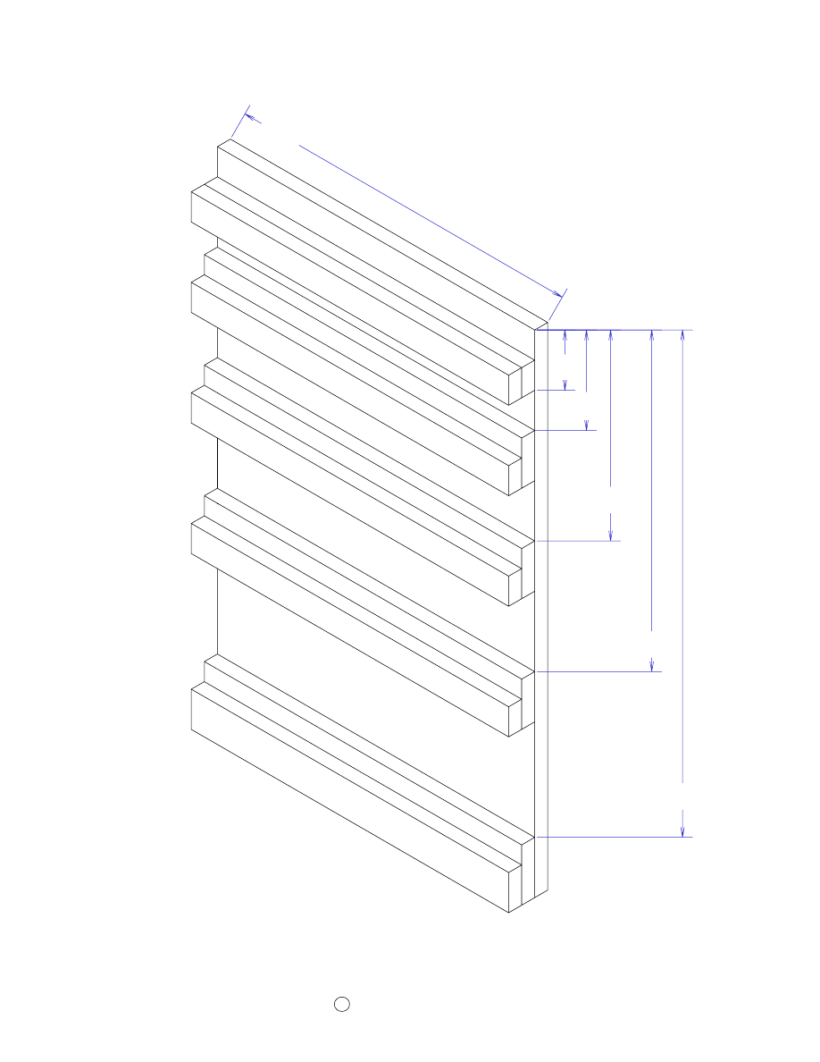
Attach Drawer Slides Left Section - Right Panel
5"
10 1/2"
17"
25 1/4"
3"
18 1/4"
Dra
wer
Su
ppo
rt
Dra
wer
Su
ppo
rt
Dra
wer
Su
ppo
rt
Low
er D
raw
er S
upp
ort
Dra
wer
Su
ppo
rt
Low
er D
raw
er S
ide
Gu
ide
Dra
wer
Sid
e G
uid
e
Dra
wer
Sid
e G
uid
e
Dra
wer
Sid
e G
uid
e
Copyright
2006 by Robert E. Reedy, Vandalia, Ohio
C
Dr
aw
er
Su
pp
ort
Dr
aw
er
Su
pp
ort
Le
ve
lin
g B
loc
k
6"
13 3/4"
26 1/4"
Lo
we
r D
raw
er
Su
pp
ort
3"
6 1/4"
11"
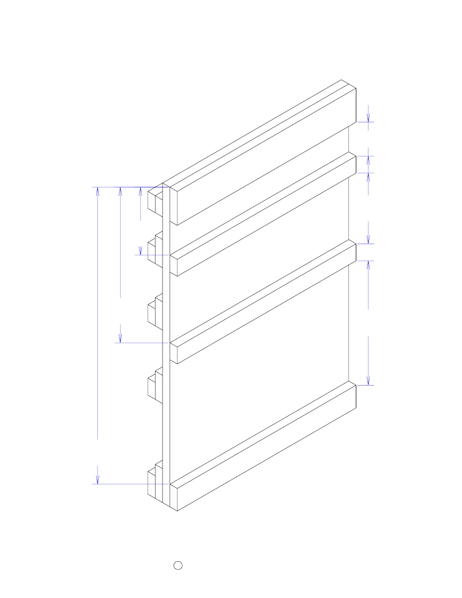
Attach Drawer Slides Center Section - Left Panel
Page 14
Copyright
2006 by Robert E. Reedy, Vandalia, Ohio
C
Left Inside Panel
Dra
wer
Su
ppo
rt
Dra
wer
Su
ppo
rt
Lev
elin
g B
lock
Low
er D
raw
er S
upp
ort
6"
13 3/4"
26 1/4"
Attach Drawer Slides Center Section - Right Panel
Copyright
2006 by Robert E. Reedy, Vandalia, Ohio
C
Right Inside Panel
Page 15
3"
3"
5"
10 1/2"
17"
25 1/4"
4"
Dr
aw
er
Sid
e G
uid
e
Dr
aw
er
Sid
e G
uid
e
Lo
we
r D
raw
er
Sid
e G
uid
e
Dr
aw
er
Su
pp
ort
Dr
aw
er
Su
pp
ort
Lo
we
r D
raw
er
Su
pp
ort
6"
Su
pp
ort
6"
Su
pp
ort
6"
Sid
e G
uid
e
Attach Drawer Slides - Right Section - Left Panel
Copyright
2006 by Robert E. Reedy, Vandalia, Ohio
C
Page 16
Right Section - Right Panel
3"
5"
10 1/2"
17"
25 1/4"
4"
5"
6 3/4"
Dra
wer
Sid
e G
uid
e
Dra
wer
Su
ppo
rt
Dra
wer
Sid
e G
uid
e
Dra
wer
Su
ppo
rt
Low
er D
raw
er S
ide
Gu
ide
Low
er D
raw
er S
upp
ort
6" S
upp
ort
6" S
ide
Gu
ide
6" S
upp
ort
6" L
eve
ler
1"
11 1
/2" L
eve
ler
Page 17
Attach Drawer Slides Right Section - Right Panel
Copyright
2006 by Robert E. Reedy, Vandalia, Ohio
C
Attach the Panels to the Base
Page 18
17 1/2"
30"
17 1/2"
Copyright
2006 by Robert E. Reedy, Vandalia, Ohio
C
Copyright
2006 by Robert E. Reedy, Vandalia, Ohio
C
St
iffe
ne
r
Attach the casters to the base as shown. Then position the stiffener as close
to the front as possible while still allowing clearance for the swival casters
to rotate. Mark the position of the stiffener, then drill about six holes for #8
wood screws through the base. Apply some glue and secure the stiffener to
the base with 2" #8 screws.
The screw heads will be inside cabinet below the drawers so it doesn't
matter if you use flathead or pan head screws..
Attach theStiffener & Casters to the Base
Page 19
At
tac
h t
he
ba
ck
to
th
e v
ert
ica
l p
an
els
an
d b
ase
w
ith
1
1/2
" #
8 f
lat
he
ad
sc
rew
s a
s s
ho
wn
.
Attach The Back
Page 20
Copyright
2006 by Robert E. Reedy, Vandalia, Ohio
C
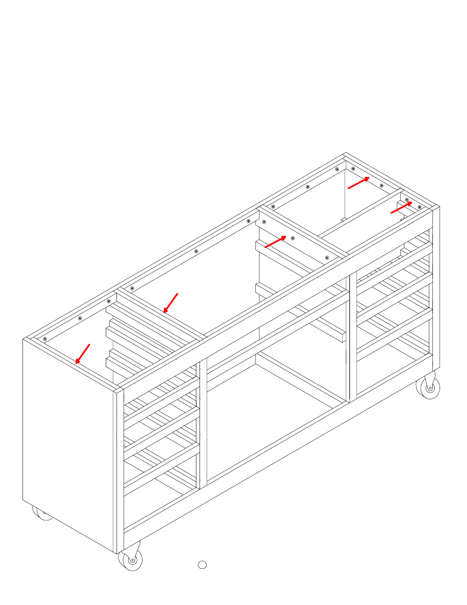
Attach the router box bottom to the
drawer slides.
Attach the middle shelf to the
supports.
Ro
ute
r B
ox
B
ot
tom
Mi
dd
le
Sh
elf
Attach the Router Box Bottom & Middle Shelf
Page 21
Copyright
2006 by Robert E. Reedy, Vandalia, Ohio
C
Copyright
2006 by Robert E. Reedy, Vandalia, Ohio
C
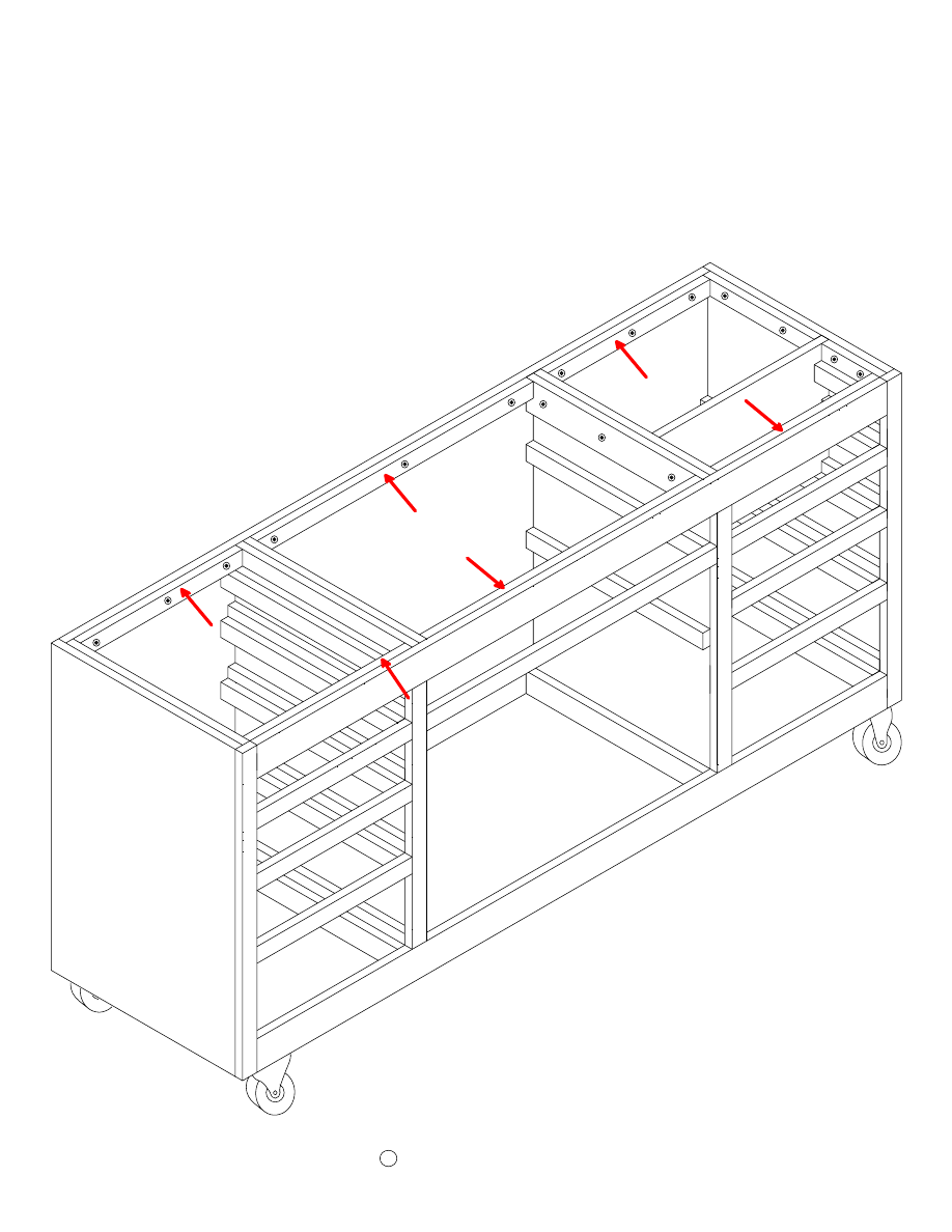
Attach the router box front to the
router box bottom and to the rear end
surface of the drawer slides.
Attach the Router Box Front
Page 22
Assemble the Face Frame
Page 23
Copyright
2006 by Robert E. Reedy, Vandalia, Ohio
C
Assemble the front trim pieces (face frame) as shown. Be sure the horizontal
drawer separator pieces are properly spaced so they line up with the drawer
slides.
The top of each piece of horizontal drawer separator trim should be flush with
the top of a drawer slide.
Pocket holes are the easiest way to join trim or face frames as they are often
called. if you don't have a pocket hole jig, you can use dowel joints.
Don't forget! The pocket holes go on
the back side of the face frame.
Copyright
2006 by Robert E. Reedy, Vandalia, Ohio
C
Attach the FaceFrame to the Cabinet
Page 24
Attach the assembled face frame to
the cabinet with finishing nails.
Then, countersink and fill the nail
holes with wood putty.
When all the blocks are level, tighten the screws and
recheck that they did not move.
Now, you are ready to attach the leveling blocks. This is the way you ensure that the top is perfectly flat
when the workbench is completed. First, drill three 1/4" diameter holes completely through each leveling
block, (the two shortest ones only need two holes). The exact location of the holes is not critical. Drill a
hole about 2" from each end and one in the middle of each leveling block. To keep the glue from setting
before you're finished, it's best to attach the end and center panel leveling blocks first and ensure they are
level with each other before attaching the front and rear ones.
After all the blocks are in place, use a
straight edge to ensure the top surfaces of all
the leveling blocks are level with each other.
If you have a four foot level, that would
work great.
Apply some glue to the mating faces and attach the end and center panel
leveling blocks using 1 1/2" #8 pan head screws with flat washers as
shown. Do not tighten the screws yet as the blocks must be leveled first.
Copyright
2006 by Robert E. Reedy, Vandalia, Ohio
C
The important thing is that the top surfaces
of the leveling blocks be level with each
other. This will provide a flat surface to
mount the sub top to.
Attach the Leveling Blocks to the End and Center Panels
Page 25
Copyright
2006 by Robert E. Reedy, Vandalia, Ohio
C
Attach the Front & Rear Leveling Blocks
Page 26
Apply glue to the mating surfaces and attach the front and rear leveling blocks as shown in the diagram.
Use your straight edge to ensure the tops are even with the tops of the end and center leveling blocks.
Then tighten the screws.
Copyright
2006 by Robert E. Reedy, Vandalia, Ohio
C
Attach the Sub Top with 1 1/2" #8
flathead screws. The Sub Top should
be flush to the edges of the cabinet
on all four sides.
Attach the Sub Top to the Cabinet
Page 27
Copyright
2006 by Robert E. Reedy, Vandalia, Ohio
C
Attach the Inner Sub Top Trim to the Sub Top
with 1 1/2" #8 flathead screws. Be sure the top
of the trim is flush with the top surface of the
Sub Top.
Attach the Inner Sub Top Trim
Page 28
Attach the Middle Trim to the Inner Sub Top Trim
Page 29
Copyright
2006 by Robert E. Reedy, Vandalia, Ohio
C
Attach the Middle Sub Top Trim to the Inner Sub Top
Trim with 1 1/2" #8 flathead screws. Be sure to space
these screws so they don't interfere with the screws in
the inner trim or the T-Track which will be attched to the
Middle Sub Top trim. The pocket holes will be used to
attach the edges of the top to the trim.
Attach the Top to the Sub Top
Page 30
Copyright
2006 by Robert E. Reedy, Vandalia, Ohio
C
Pocket Hole Screws
Attach the Top to the Sub Top with 1" #8 flathead screws through the cutouts for the T-Track and Miter
guage track. Secure the edges of the top with pocket hole screws through the holes you drilled through
the Inner Sub Top Trim. If you don't have a pocket hole jig, you can glue the Top to the Sub Top.
However, gluing it will make it much more difficult to replace the top in the future if you need to.
Note: The dimensions given in these plans are
based using T-Track that is 3/4" wide and 1/2"
thick. If your T-Track is a different size, you will
need to modify the thickness of the inner trim
accordingly.
Attach the T-Track & Miter track to the Top
Page 31
Copyright
2006 by Robert E. Reedy, Vandalia, Ohio
C
Attach the Lower Track Support to the left side
of the cabinet with six 2" #8 flathead screws.
Position this piece so it is 1" below the Sub Top
Trim and centered front to back.
Attach the T-Track to the top as shown with 1" #6 screws. Some manufacturers countersink the holes for
mounting the track and others do not. From my experience, I prefer flathead screws with countersunk
holes. This keeps the screw heads from interfering with the bolts sliding through the track. The track I
used for the prototype was designed for pan head screws, so I countersunk them on my drill press.
The miter guage track is not subject to much stress so you can glue it in the slot. If you use screws, be
sure the screw heads are below the surface so the miter guage does not hang up on them. I would not
reccommend polyurethane glues because they expand as they set up. The expanding glue would lift the
miter track up above the surface of the workbench top. A construction adhesive like liquid nails works
fine.
Top T-Track
Miter Guage Track
Attach the T-Track to the Edges of the Front and Ends
Page 32
Copyright
2006 by Robert E. Reedy, Vandalia, Ohio
C
Attach the edge T-Track on each end and along the front to the middle Sub Top Trim with 1" #6 screws.
Position this T-Track under the bottom surface of the Top as shown in the detail drawing.
T-Track joins at the corners like
this so you can slide the bolts in
and out.
End T-Track
Front T-Track
End T-Track
Detail
Attach the Lower T-Track to the Lower T-Track
Support. The T-Track should be centered top to
bottom.
Attach the Lower Front Trim to the Front and Ends
Page 33
Copyright
2006 by Robert E. Reedy, Vandalia, Ohio
C
Detail
Attach the Lower Top Trim on each end and along the front to the middle Sub Top Trim with 1 1/2"
finishing nails.
If you cut the top a little larger than the dimensions called for, you can trim it with your router and a
flush trimming bit. Use the Lower Top Trim for the bit bearing to follow.
The Lower Top Trim joins at
the corners like this.
Lower Trim
Attach the Lower Track Trim with finishing
nails.
Lower Trim
Step 2
Step 3
Left Side
Step 1
Right Side
Front
Back
Step 5
Step 4
Support the drawer boxes with 1/4" thick strips of wood and attach the drawer fronts
with 1 1/8" screws as shown. This is necessary because the bottom of the front must
be 1/4" below the bottom of the box so it will overlap the rear cabinet trim when
installed.
Apply a little glue to the mating surfaces and assemble the drawer boxes.
Assemble the front, back, and right side with finishing nails as shown in Step 1.
Insert the bottom as shown in Step 2. Attach the left side as shown in Step 3.
Assemble the Drawers
Page 34
Copyright
2006 by Robert E. Reedy, Vandalia, Ohio
C
Assemble the Router Bit Trays
Page 34
Copyright
C
2006 by Robert E. Reedy, Vandalia, Ohio
Attach the drawer fronts to the router tray fronts with pocket hole screws on each side as shown.
Don't forget to support the trays with 1/4" thick strips of wood while you attach the fronts. As with
the drawers, the bottom of the fronts must be 1/4" below the bottom of the trays so the fronts will
overlap the cabinet trim when installed.
Assemble the Router trays with finishing nails as shown above.

Attach the Cabinet Doors
Page 36
Copyright
2006 by Robert E. Reedy, Vandalia, Ohio
C
Attach the cabinet doors so the tops align with the tops of the
drawers and the sides align with the ends of the middle drawer as
shown above.
Attach the Middle Door trim
Page 37
Copyright
2006 by Robert E. Reedy, Vandalia, Ohio
C
Attach the Middle Door Lip to the back of either of the cabinet
doors so half of it is visible as shown. Attach it to the back of the
door with a couple of 1" wood screws. The left door is not
pictured in the drawing for clarity.
This piece serves as a door lip so there is no visible gap between
the doors.
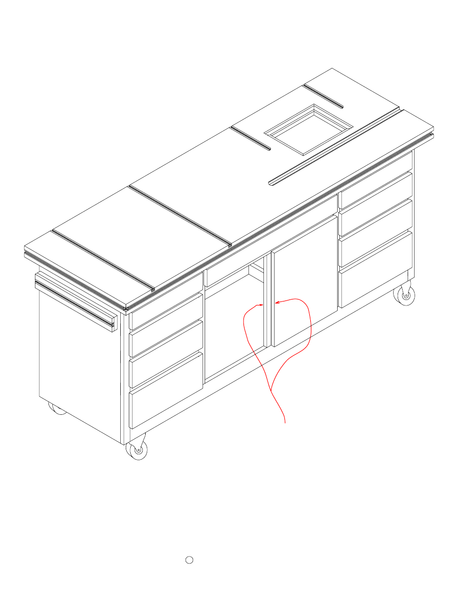
Now, you're ready to attach the Drawer and Door handles and your work bench is finished.
Clamping System Parts
Page 38
Copyright
C
2006 by Robert E. Reedy, Vandalia, Ohio
"
2
3/8" Button Hole
Clamp Jaw Layout (Side 2)
"
2 3/4
5/16" Bolt Hole
3/8" Button Hole
"
3 1/2
Clamp Jaw Layout (Side 1)
2"
4 1/2"
Clamp Jaws (2)
5/8"
3 1/2"
1 1/2"
2 3/4"
E
n
d
V
ie
w
3"
3"
1 1/2"
Rear Stop
Dia - 5/16"
24"
Dia - 5/16"
1 3/4"
1 3/4"
2"
28"
EZ Clamp Stop
Post (2)
2"
2 1/2"
Drill two pocket holes in each Post as shown below. Next, drill two
1/4" diameter holes in the end of each Post as shown. (The 1/4" holes
should only be 1/2" deep.)
2"
4"
Jaws (2)
1/2"
Posts
Dia - 5/16"
1/2"
3/8"
Jaws
"
2 1/4
Drill a 5/16" bolt through each jaw as
shown. Next, drill two 5/16" holes for the
dowel pins in each Jaw as shown. (The
dowel pin holes are 5/16" diameter so the
Jaws can pivot over the pins. These holes
should be 1/2" deep.)
Assemble the EZ Mount Stop
Page 39
Copyright
C
2006 by Robert E. Reedy, Vandalia, Ohio
Attach the Posts to the ends of the Stop Bar with pocket hole screws as
shown below. Next, cut four 7/8" long dowel pins from 1/4" dowel
rod. Apply some glue and insert a 1/4" dowel pin into each hole in the
ends of the Posts. (The dowel pins should protude about 3/8" from the
ends of the Posts.)
Place the Jaws over the protuding dowel pins as shown above. (Do not
glue the dowel pins to the Jaws as the Jaws must be allowed to pivot
in order to work as clamps.) Insert a 5/16 carriage bolt through the
holes as shown. (The carriage bolt should be 5" long. Secure the
pieces with a flat washer and knob.

Clamping System Usage
Page 40
Copyright
C
2006 by Robert E. Reedy, Vandalia, Ohio
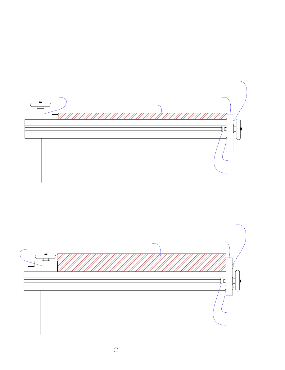
The T-Track clamping system provides a flexible way of clamping both large and small
work pieces. Most work pieces can be clamped using the two Clamp Jaws and the Rear
Stop. The Clamp Jaws are used with the T-Track that runs along the front edge of the
workbench. The Rear Stop is used with the T-Track that is embedded in the top surface of
the workbench.
For longer workpieces, you can use the the Clamp Jaws with the T-Track on the ends of the
workbench. The EZ Mount Stop may be secured anywhere along the workbench top. The
simple clamps on each end of the EZ Mount Stop grip the edge of the workbench top as
well as C-Clamps. This feature enables you to use the workbench as a large bar clamp for
gluing up boards.
You can make the clamping system grip the work piece even tighter by gluing strips of 100
grit sandpaper along the edges that contact the workpiece. The sandpaper requires much
less force than the surface of bare wood.
The button arrangement on the Clamp Jaws allows you to filp the Clamp Jaws over for
thicker work pieces. The drawings on the next two pages illustrates how the clamps work.
To clamp a work piece, position the workpiece so the edge protudes slightly over the edge
of the workbench top as shown. Then, position the Rear Stop against the workpiece and
tighten it to T-Track using the knobs. Next, tighten the Clamp Jaws against the workpiece
with the knobs and your work piece will be clamped just like with a vice.
For thinner workpieces, position the Clamp Jaws and Rear Stop as shown. If your
workpiece is thinner than 3/4", you can place strips of wood under the work piece so it is
slightly higher than the top edges of the Clamp Jaws.
For thicker workpieces, flip the Clamp Jaws so the second button is against the Lower
T-Track Trim and reverse the Rear Stop so the thicker edge is against the workpiece.
Using the Clamps
Page 41
Copyright
C
2006 by Robert E. Reedy, Vandalia, Ohio
Rear Stop
T-Track
Second Button
Button
Clamp Jaw
Workpiece
For thicker workpieces, flip the Clamp Jaw so the second button is against the Lower T-Track Trim
and reverse the Rear Stop so the thicker edge is against the workpiece.
T-Track
Button
Second Button
Clamp Jaw
Workpiece
Rear Stop
For thinner workpieces, position the Clamp Jaws and Rear Stop as shown.
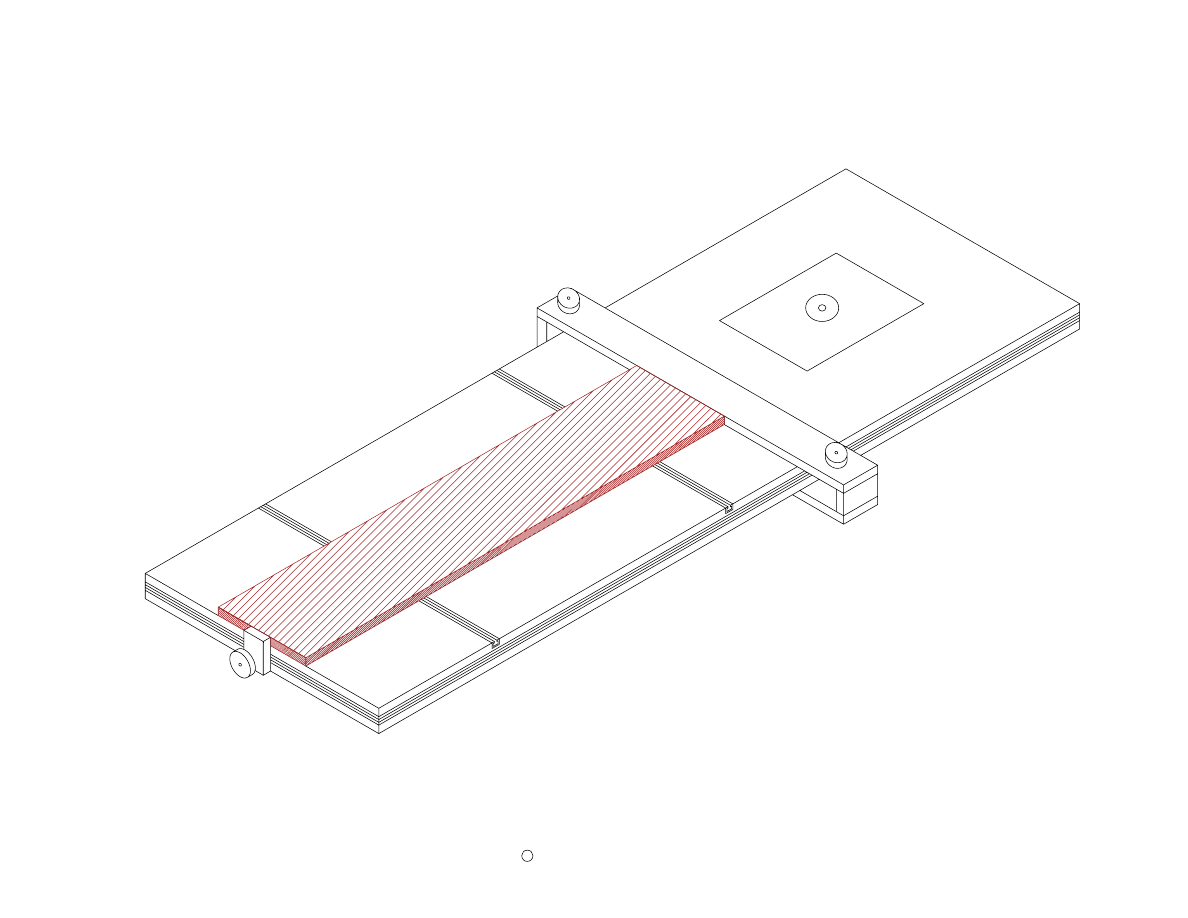
Clamping Long Workpieces
To clamp long work pieces, use the
Clamping Jaws and EZ Mount Stop as
shown.
Copyright c
by Robert E. Reedy, Vandalia, Ohio
Page 41
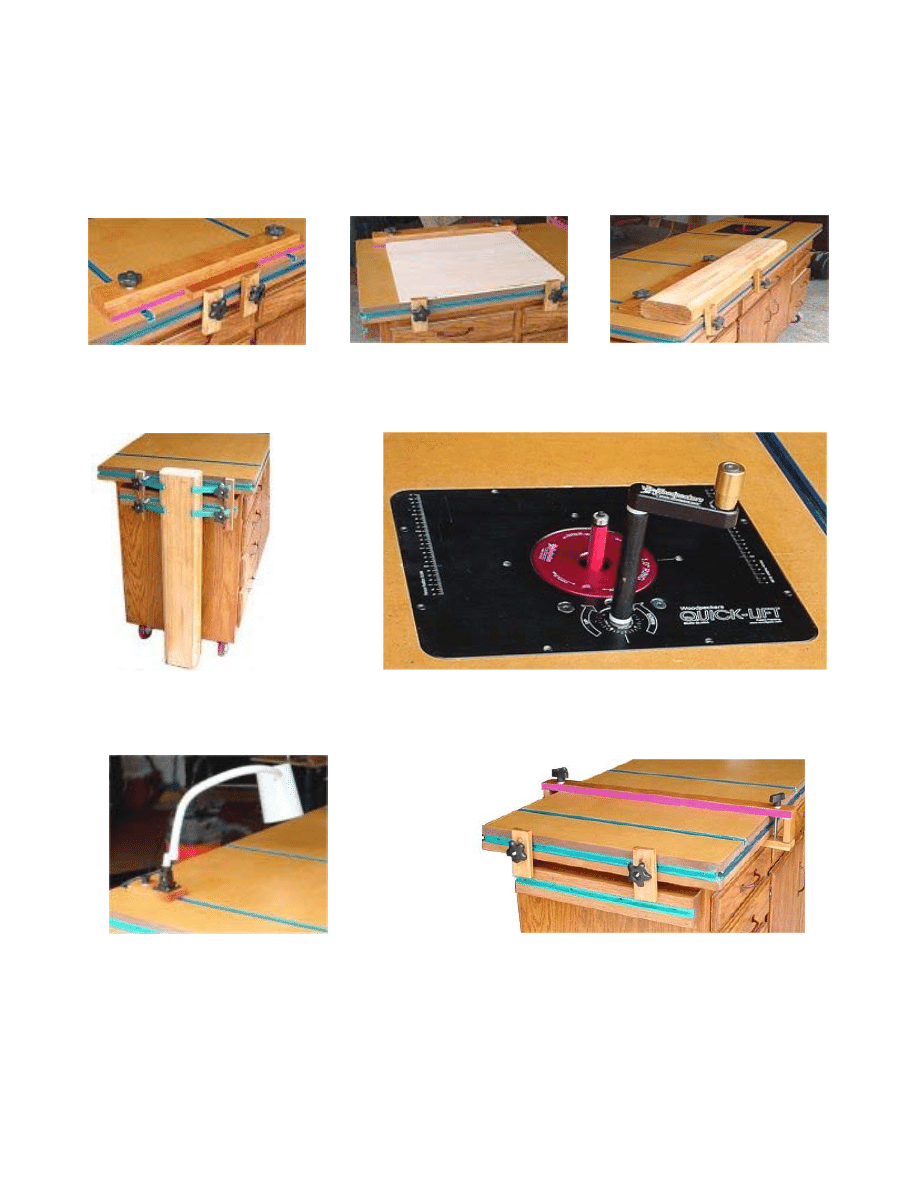
Snapshots
Clamping a small work piece
Clamping a large work piece
Clamping a thick work piece
Clamp a large work piece
Hold down clamps.
Close up view of the Woodpeckers Quick-Lift.
Clamping a work light.
Arranging the jaws for use with the EZ Mount Stop.
The purple edge is the 100 grit sandpaper used to
make the stop grip the work piece tighter.
Wyszukiwarka
Podobne podstrony:
Cwiczenie 6 WorkBench czwórniki pasywne
workbench
workbench
ANSYS Getting Started Tutorial Workbench
Do it Yourself Workbench id 137 Nieznany
Electronics Workbench 4 0 opis programu
WZÓR SPRAWOZDANIA ANSYS WORKBENCH=
Bauanleitung Instructions Workbee
(madera) Woodworking plans Workbench Popular Mechanics Hard Maple
(EBooks) DIY Woodwork Plans 10 Workbench Accessories
WorkBench workbench
Space Saver Workbench
Do it Yourself Workbench
Shop Notes WorkBench Top with Hold down Tracks
Developing your STM32VLDISCOVERY application using the IAR Embedded Workbench
WorkBench Monterey Potting Center
Woodwork Plans Workbench
Workbench1
więcej podobnych podstron