
HEATING AND AIR CONDITIONING
TABLE OF CONTENTS
page
page
DESCRIPTION AND OPERATION
SERVICE WARNINGS AND PRECAUTIONS . . . . . 1
COMPRESSOR - 2.5L VM DIESEL . . . . . . . . . . . . 3
COMPRESSOR CLUTCH - 2.5L VM DIESEL . . . . 3
REMOVAL AND INSTALLATION
SUCTION AND DISCHARGE LINE . . . . . . . . . . . . 4
COMPRESSOR - 2.5L VM DIESEL . . . . . . . . . . . . 6
COMPRESSOR CLUTCH - 2.5L VM DIESEL . . . . 8
DESCRIPTION AND OPERATION
SERVICE WARNINGS AND PRECAUTIONS
WARNING:
•
THE AIR CONDITIONING SYSTEM CONTAINS
REFRIGERANT UNDER HIGH PRESSURE. SEVERE
PERSONAL INJURY MAY RESULT FROM IMPROPER
SERVICE PROCEDURES. REPAIRS SHOULD ONLY
BE PERFORMED BY QUALIFIED SERVICE PERSON-
NEL.
•
AVOID BREATHING THE REFRIGERANT AND
REFRIGERANT OIL VAPOR OR MIST. EXPOSURE
MAY IRRITATE THE EYES, NOSE, AND/OR THROAT.
WEAR EYE PROTECTION WHEN SERVICING THE
AIR CONDITIONING REFRIGERANT SYSTEM. SERI-
OUS EYE INJURY CAN RESULT FROM DIRECT
CONTACT WITH THE REFRIGERANT. IF EYE CON-
TACT OCCURS, SEEK MEDICAL ATTENTION IMME-
DIATELY.
•
DO
NOT
EXPOSE
THE
REFRIGERANT
TO
OPEN
FLAME.
POISONOUS
GAS
IS
CREATED
WHEN
REFRIGERANT
IS
BURNED.
AN
ELEC-
TRONIC LEAK DETECTOR IS RECOMMENDED.
•
IF
ACCIDENTAL
SYSTEM
DISCHARGE
OCCURS, VENTILATE THE WORK AREA BEFORE
RESUMING
SERVICE.
LARGE
AMOUNTS
OF
REFRIGERANT RELEASED IN A CLOSED WORK
AREA WILL DISPLACE THE OXYGEN AND CAUSE
SUFFOCATION.
•
THE EVAPORATION RATE OF R-134a REFRIG-
ERANT AT AVERAGE TEMPERATURE AND ALTI-
TUDE
IS
EXTREMELY
HIGH.
AS
A
RESULT,
ANYTHING THAT COMES IN CONTACT WITH THE
REFRIGERANT WILL FREEZE. ALWAYS PROTECT
THE SKIN OR DELICATE OBJECTS FROM DIRECT
CONTACT WITH THE REFRIGERANT.
•
THE R-134a SERVICE EQUIPMENT OR THE
VEHICLE REFRIGERANT SYSTEM SHOULD NOT BE
PRESSURE TESTED OR LEAK TESTED WITH COM-
PRESSED AIR. SOME MIXTURES OF AIR AND
R-134a HAVE BEEN SHOWN TO BE COMBUSTIBLE
AT ELEVATED PRESSURES. THESE MIXTURES ARE
POTENTIALLY DANGEROUS, AND MAY RESULT IN
FIRE OR EXPLOSION CAUSING INJURY OR PROP-
ERTY DAMAGE.
XJ
HEATING AND AIR CONDITIONING
24 - 1

CAUTION:
•
Liquid refrigerant is corrosive to metal sur-
faces. Follow the operating instructions supplied
with the service equipment being used.
•
Never
add
R-12
to
a
refrigerant
system
designed to use R-134a. Damage to the system will
result.
•
R-12 refrigerant oil must not be mixed with
R-134a refrigerant oil. They are not compatible.
•
Do not use R-12 equipment or parts on the
R-134a system. Damage to the system will result.
•
Do not overcharge the refrigerant system. This
will cause excessive compressor head pressure
and can cause noise and system failure.
•
Recover the refrigerant before opening any fit-
ting or connection. Open the fittings with caution,
even after the system has been discharged. Never
open or loosen a connection before recovering the
refrigerant.
•
Do not remove the secondary retention clip
from any spring-lock coupler connection while the
refrigerant system is under pressure. Recover the
refrigerant before removing the secondary retention
clip. Open the fittings with caution, even after the
system has been discharged. Never open or loosen
a connection before recovering the refrigerant.
•
The refrigerant system must always be evacu-
ated before charging.
•
Do not open the refrigerant system or uncap a
replacement component until you are ready to ser-
vice the system. This will prevent contamination in
the system.
•
Before disconnecting a component, clean the
outside of the fittings thoroughly to prevent con-
tamination from entering the refrigerant system.
•
Immediately after disconnecting a component
from the refrigerant system, seal the open fittings
with a cap or plug.
•
Before connecting an open refrigerant fitting,
always install a new seal or gasket. Coat the fitting
and seal with clean refrigerant oil before connect-
ing.
•
Do not remove the sealing caps from a replace-
ment component until it is to be installed.
•
When installing a refrigerant line, avoid sharp
bends that may restrict refrigerant flow. Position the
refrigerant lines away from exhaust system compo-
nents or any sharp edges, which may damage the
line.
•
Tighten refrigerant fittings only to the specified
torque. The aluminum fittings used in the refriger-
ant system will not tolerate overtightening.
•
When disconnecting a refrigerant fitting, use a
wrench on both halves of the fitting. This will pre-
vent twisting of the refrigerant lines or tubes.
•
Refrigerant oil will absorb moisture from the
atmosphere if left uncapped. Do not open a con-
tainer of refrigerant oil until you are ready to use it.
Replace the cap on the oil container immediately
after using. Store refrigerant oil only in a clean, air-
tight, and moisture-free container.
•
Keep service tools and the work area clean.
Contamination of the refrigerant system through
careless work habits must be avoided.
COOLING SYSTEM REQUIREMENTS
To maintain the performance level of the heating-
air conditioning system, the engine cooling system
must be properly maintained. The use of a bug
screen is not recommended. Any obstructions in front
of the radiator or condenser will reduce the perfor-
mance of the air conditioning and engine cooling sys-
tems.
The engine cooling system includes the heater core
and the heater hoses. Refer to Group 7 - Cooling Sys-
tem for more information before the opening of, or
attempting any service to the engine cooling system.
REFRIGERANT HOSES/LINES/TUBES
PRECAUTIONS
Kinks or sharp bends in the refrigerant plumbing
will reduce the capacity of the entire system. High
pressures are produced in the system when it is oper-
ating. Extreme care must be exercised to make sure
that all refrigerant system connections are pressure
tight.
A good rule for the flexible hose refrigerant lines is
to keep the radius of all bends at least ten times the
diameter of the hose. Sharp bends will reduce the
flow of refrigerant. The flexible hose lines should be
routed so they are at least 80 millimeters (3 inches)
from the exhaust manifold. It is a good practice to
inspect all flexible refrigerant system hose lines at
least once a year to make sure they are in good con-
dition and properly routed.
There are two types of refrigerant fittings:
• All fittings with O-rings need to be coated with
refrigerant oil before installation. Use only O-rings
that are the correct size and approved for use with
R-134a refrigerant. Failure to do so may result in a
leak.
• Unified plumbing connections with gaskets can-
not be serviced with O-rings. The gaskets are not
reusable and new gaskets do not require lubrication
before installing.
Using the proper tools when making a refrigerant
plumbing connection is very important. Improper
tools or improper use of the tools can damage the
refrigerant fittings. Always use two wrenches when
loosening or tightening tube fittings. Use one wrench
24 - 2
HEATING AND AIR CONDITIONING
XJ
DESCRIPTION AND OPERATION (Continued)
to hold one side of the connection stationary, while
loosening or tightening the other side of the connec-
tion with a second wrench.
The refrigerant must be recovered completely from
the system before opening any fitting or connection.
Open the fittings with caution, even after the refrig-
erant has been recovered. If any pressure is noticed
as a fitting is loosened, tighten the fitting and
recover the refrigerant from the system again.
Do not discharge refrigerant into the atmosphere.
Use an R-134a refrigerant recovery/recycling device
that meets SAE Standard J2210.
The refrigerant system will remain chemically sta-
ble as long as pure, moisture-free R-134a refrigerant
and refrigerant oil is used. Dirt, moisture, or air can
upset this chemical stability. Operational troubles or
serious damage can occur if foreign material is
present in the refrigerant system.
When it is necessary to open the refrigerant sys-
tem, have everything needed to service the system
ready. The refrigerant system should not be left open
to the atmosphere any longer than necessary. Cap or
plug all lines and fittings as soon as they are opened
to prevent the entrance of dirt and moisture. All lines
and components in parts stock should be capped or
sealed until they are to be installed.
All tools, including the refrigerant recycling equip-
ment, the manifold gauge set, and test hoses should
be kept clean and dry. All tools and equipment must
be designed for R-134a refrigerant.
COMPRESSOR - 2.5L VM DIESEL
DESCRIPTION
The 2.5L diesel engine uses a Denso 10PA17 seven
cylinder, reciprocating wobble plate-type compressor.
This compressor has a fixed displacement of 150
cubic centimeters (9.375 cubic inches), and has both
the suction and discharge ports located on the com-
pressor cylinder head. A label identifying the use of
R-134a refrigerant is located on the compressor.
OPERATION
The compressor is driven by the engine through
the power steering pump main shaft. The power
steering pump is driven by the accessory drive belt.
The compressor is lubricated by refrigerant oil that
is circulated throughout the refrigerant system with
the refrigerant. The compressor draws in low-pres-
sure refrigerant vapor from the evaporator through
its suction port. It then compresses the refrigerant
into a high-pressure, high-temperature refrigerant
vapor, which is then pumped to the condenser
through the compressor discharge port.
The compressor cannot be repaired. If faulty or
damaged, the entire compressor assembly must be
replaced. The compressor clutch, pulley and clutch
coil are available for service.
COMPRESSOR CLUTCH - 2.5L VM DIESEL
DESCRIPTION
The compressor clutch assembly used on the diesel
engine is the same clutch used on most compressors
however, due to the different drive arrangement it
utilizes a drive cup that threads onto the clutch drive
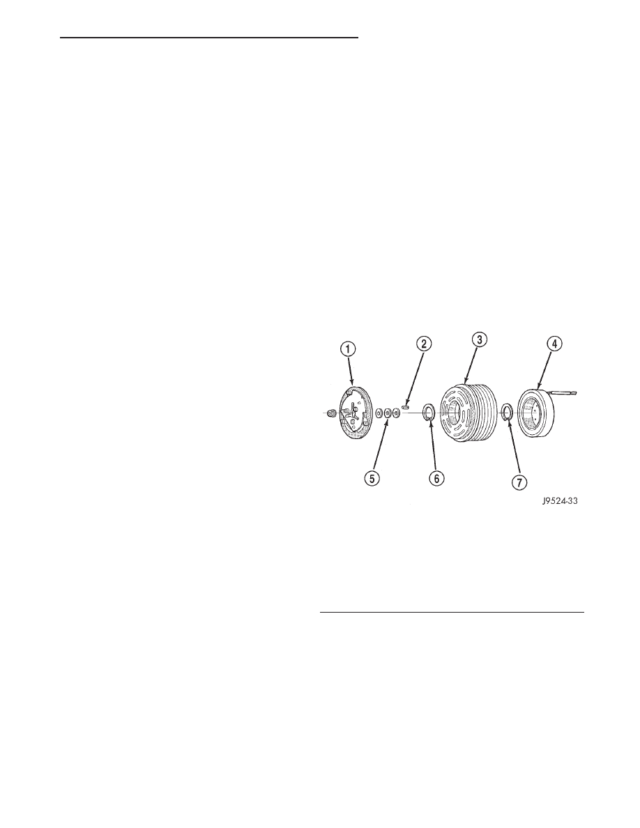
pulley. The basic compressor clutch assembly consists
of a stationary electromagnetic coil, a hub bearing
and pulley assembly, and a clutch plate (Fig. 1). The
electromagnetic coil unit and the hub bearing and
pulley assembly are each retained on the nose of the
compressor front housing with snap rings. The clutch
plate is keyed to the compressor shaft and secured
with a nut. These components provide the means to
engage and disengage the compressor from the
engine serpentine accessory drive belt.
OPERATION
When the clutch coil is energized, it magnetically
draws the clutch into contact with the pulley and
drives the compressor shaft. When the coil is not
energized, the pulley freewheels on the clutch hub
bearing, which is part of the pulley. The compressor
clutch and coil are the only serviced parts on the
compressor.
The compressor clutch engagement is controlled by
several components: the heater-A/C mode control
switch, the low pressure cycling clutch switch, the
dual function high pressure switch, the compressor
Fig. 1 Compressor Clutch – Drive Cup Not Shown
1 – CLUTCH PLATE
2 – SHAFT KEY
3 – PULLEY
4 – COIL
5 – CLUTCH SHIMS
6 – SNAP RING
7 – SNAP RING
XJ
HEATING AND AIR CONDITIONING
24 - 3
DESCRIPTION AND OPERATION (Continued)
clutch relay, and the Powertrain Control Module
(PCM). The PCM may delay compressor clutch
engagement for up to thirty seconds. Refer to Group
14 - Fuel System for more information on the PCM
controls.
REMOVAL AND INSTALLATION
SUCTION AND DISCHARGE LINE
Any kinks or sharp bends in the refrigerant plumb-
ing will reduce the capacity of the entire air condi-
tioning system. Kinks and sharp bends reduce the
flow of refrigerant in the system. A good rule for the
flexible hose refrigerant lines is to keep the radius of
all bends at least ten times the diameter of the hose.
In addition, the flexible hose refrigerant lines should
be routed so they are at least 80 millimeters (3
inches) from the exhaust manifold.
High pressures are produced in the refrigerant sys-
tem when the air conditioning compressor is operat-
ing. Extreme care must be exercised to make sure
that each of the refrigerant system connections is
pressure-tight and leak free. It is a good practice to
inspect all flexible hose refrigerant lines at least once
a year to make sure they are in good condition and
properly routed.
WARNING: REVIEW THE WARNINGS AND CAU-
TIONS IN THE FRONT OF THIS GROUP BEFORE
PERFORMING THE FOLLOWING OPERATION.
LEFT-HAND DRIVE
REMOVAL
(1) Disconnect and isolate the battery negative
cable.
(2) Recover the refrigerant from the refrigerant
system. See Refrigerant Recovery in this group for
the procedures.
(3) Unplug the wire harness connector from the
high pressure cut-off switch.
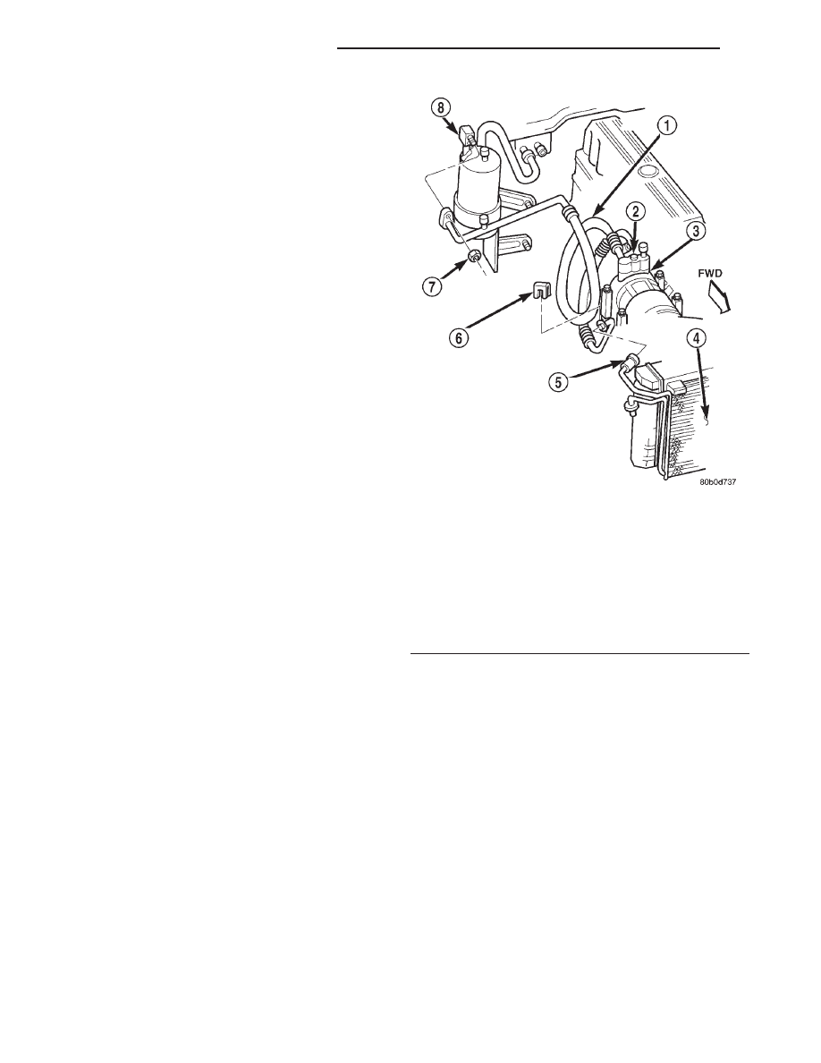
(4) Disconnect the discharge line refrigerant line
fitting from the condenser inlet tube (Fig. 2). See
Refrigerant Line Coupler in this group for the proce-
dures. Install plugs in, or tape over all of the opened
refrigerant line fittings.
(5) Remove the nut that secures the suction line
block fitting to the accumulator outlet. Install plugs
in, or tape over all of the opened refrigerant line fit-
tings.
(6) Remove the screw that secures the suction and
discharge line manifold to the compressor. Install
plugs in, or tape over all of the opened refrigerant
line fittings.
(7) Remove the suction and discharge line assem-
bly from the vehicle.
INSTALLATION
(1) Remove the tape or plugs from the suction and
discharge line manifold and the compressor. Install
the suction and discharge line manifold to the com-
pressor. Tighten the mounting screw to 28 N·m (250
in. lbs.).
(2) Remove the tape or plugs from the suction line
and the accumulator outlet block fittings. Install the
suction line to the accumulator outlet and tighten the
mounting nut to 9 N·m (80 in. lbs.).
(3) Remove the tape or plugs from the refrigerant
line fittings on the discharge line and the condenser
inlet tube. Connect the discharge line refrigerant line
coupler to the condenser inlet tube. See Refrigerant
Line Coupler in this group for the procedures.
(4) Plug in the wire harness connector to the high
pressure cut-off switch.
(5) Connect the battery negative cable.
Fig. 2 Suction and Discharge Line Remove/Install -
Left-Hand Drive
1 – SUCTION AND DISCHARGE LINE
2 – SCREW
3 – COMPRESSOR
4 – CONDENSER
5 – INLET
6 – CLIP
7 – HEX NUT
8 – ACCUMULATOR
24 - 4
HEATING AND AIR CONDITIONING
XJ
DESCRIPTION AND OPERATION (Continued)
(6) Evacuate the refrigerant system. See Refriger-
ant System Evacuate in this group for the proce-
dures.
(7) Charge the refrigerant system. See Refrigerant
System Charge in this group for the procedures.
RIGHT-HAND DRIVE - 2.5L ENGINE
REMOVAL
(1) Disconnect and isolate the battery negative
cable.
(2) Recover the refrigerant from the refrigerant
system. See Refrigerant Recovery in this group for
the procedures.
(3) Unplug the wire harness connector from the
high pressure cut-off switch.
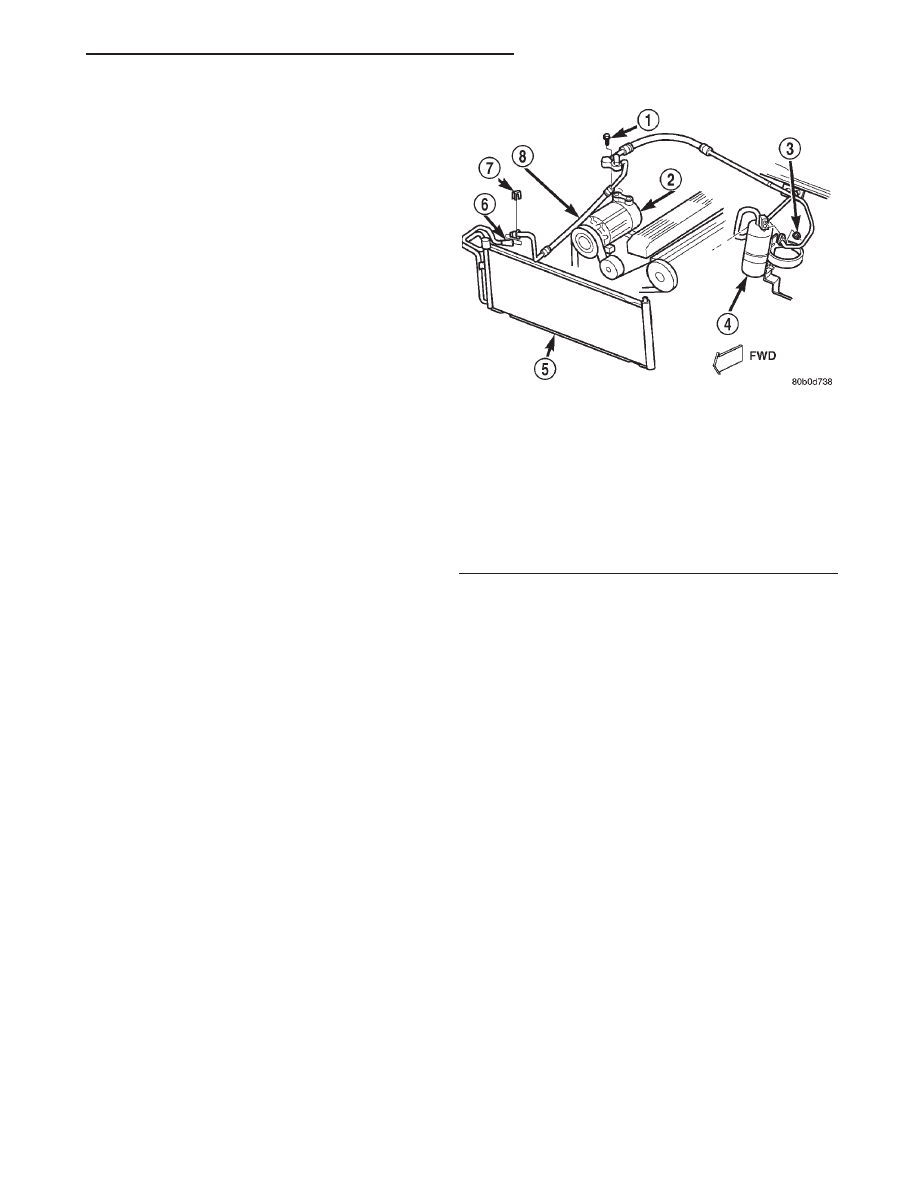
(4) Disconnect the discharge line refrigerant line
fitting from the condenser inlet tube (Fig. 3). See
Refrigerant Line Coupler in this group for the proce-
dures. Install plugs in, or tape over all of the opened
refrigerant line fittings.
(5) Remove the nut that secures the suction line
block fitting to the accumulator outlet. Install plugs
in, or tape over all of the opened refrigerant line fit-
tings.
(6) Remove the screw that secures the suction and
discharge line manifold to the compressor. Install
plugs in, or tape over all of the opened refrigerant
line fittings.
(7) Remove the suction and discharge line assem-
bly from the vehicle.
INSTALLATION
(1) Remove the tape or plugs from the suction and
discharge line manifold and the compressor. Install
the suction and discharge line manifold to the com-
pressor. Tighten the mounting screw to 28 N·m (250
in. lbs.).
(2) Remove the tape or plugs from the suction line
and the accumulator outlet block fittings. Install the
suction line to the accumulator outlet and tighten the
mounting nut to 9 N·m (80 in. lbs.).
(3) Remove the tape or plugs from the refrigerant
line fittings on the discharge line and the condenser
inlet tube. Connect the discharge line refrigerant line
coupler to the condenser inlet tube. See Refrigerant
Line Coupler in this group for the procedures.
(4) Plug in the wire harness connector to the high
pressure cut-off switch.
(5) Connect the battery negative cable.
(6) Evacuate the refrigerant system. See Refriger-
ant System Evacuate in this group for the proce-
dures.
(7) Charge the refrigerant system. See Refrigerant
System Charge in this group for the procedures.
Fig. 3 Suction and Discharge Line Remove/Install -
Right-Hand Drive 2.5L Engine
1 – SCREW
2 – COMPRESSOR
3 – HEX NUT
4 – ACCUMULATOR
5 – CONDENSER
6 – INLET
7 – CLIP
8 – SUCTION AND DISCHARGE LINE
XJ
HEATING AND AIR CONDITIONING
24 - 5
REMOVAL AND INSTALLATION (Continued)
RIGHT-HAND DRIVE - 4.0L ENGINE
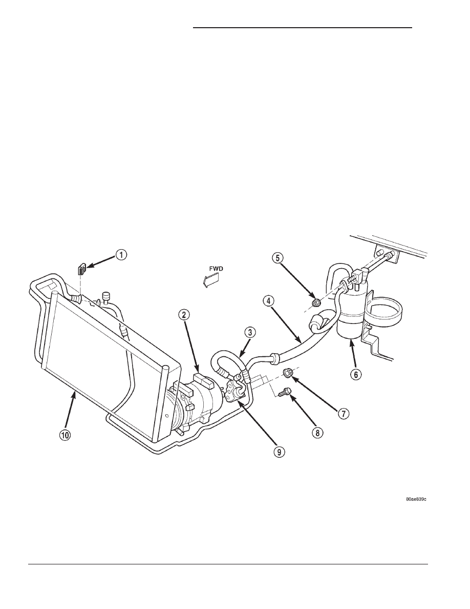
The suction and discharge lines for this model are
individual components and are secured to a manifold
block on the compressor with block fittings (Fig. 4).
There is also a jumper line installed between the dis-
charge line and the condenser inlet that is secured
with refrigerant line couplers at each end. Each of
these components is available as a separate service
part.
The suction and discharge line components can be
removed from or installed on the vehicle individually,
or as a unit. Otherwise, the service procedures are
the same as those for the other applications. Tighten
the additional mounting hardware as follows:
• Suction line to manifold block nut - 9 N·m (80
in. lbs.)
• Discharge line to manifold block nut - 9 N·m (80
in. lbs.)
• Manifold block to compressor screw - 28 N·m
(250 in. lbs.).
COMPRESSOR - 2.5L VM DIESEL
REMOVAL
(1) Disconnect the negative battery cable.
(2) Recover the refrigerant. See Refrigerant Recov-
ery in this group for the procedure.
(3) Disconnect the A/C compressor clutch electrical
connector (Fig. 5).
(4) Remove the suction and discharge refrigerant
line retaining bolts from the compressor and plug the
openings.
(5) Raise the vehicle on a hoist.
(6) Loosen all (4) H-block retaining bolts. Do not
remove at this time.
Fig. 4 Suction and Discharge Line Remove/Install - Right-Hand Drive 4.0L Engine
1 – CLIP
2 – COMPRESSOR
3 – DISCHARGE LINE
4 – SUCTION LINE
5 – NUT
6 – ACCUMULATOR
7 – NUT
8 – SCREW
9 – MANIFOLD BLOCK
10 – CONDENSER
24 - 6
HEATING AND AIR CONDITIONING
XJ
REMOVAL AND INSTALLATION (Continued)
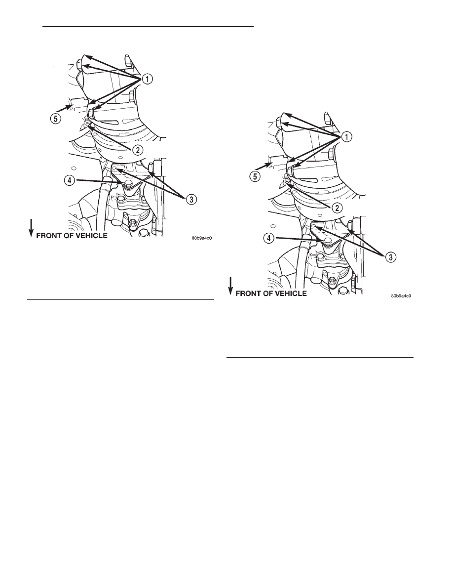
NOTE: Mark the H-Block position in relation to the
power steering pump so it may be reinstalled in the
same position.
(7) Remove the (2) H-block bolts from the power
steering pump side of the block (Fig. 5).
(8) Remove the serpentine drive belt. Refer to
Group 7, Cooling System for the procedure.
(9) Loosen, but do not remove, the coupler pinch
bolt and slide the coupler towards the pump (Fig. 5).
NOTE: There are 4 spacers located between the
engine block and the A/C compressor. The doweled
spacers are located in the front, undoweled in the
rear.
(10) Remove the (4) A/C compressor retaining bolts
(Fig. 5).
(11) Remove the compressor assembly from the
vehicle with H-Block attached.
CAUTION: Check the refrigerant oil level in the new
compressor prior to installation. See compressor oil
level in this group for a detailed procedure.
INSTALLATION
(1) Transfer the H-Block to the new compressor
and leave the bolts loose at this time.
(2) Lift the A/C compressor in position and install
the (4) spacers and retaining bolts (Fig. 6). Torque
the bolts to 33 N·m (25 ft. lbs.).
(3) Slide the drive coupler into its original position
and start the remaining (2) H-Block bolts (Fig. 6).
(4) Install the serpentine drive belt. See Group 7,
Cooling System for the procedure.
(5) Torque all H-Block retaining bolts to 33 N·m
(25 ft. lbs.).
(6) Lower the vehicle from the hoist.
(7) Install the suction and discharge refrigerant
lines on the compressor, making sure the o-rings are
well lubricated with refrigerant oil and free of tears.
(8) Connect the A/C compressor electrical connec-
tor (Fig. 6).
(9) Connect the negative battery cable.
(10) Charge the refrigerant system. See Refriger-
ant System Charge in this group for procedure.
Fig. 5 A/C Compressor Position & Orientation
1 – A/C COMPRESSOR MOUNTING BOLTS
2 – LEFT ENGINE MOUNT THROUGHBOLT NUT
3 – H BLOCK BOLTS
4 – COUPLER PINCH BOLT
5 – COMPRESSOR ELECTRICAL CONNECTOR
Fig. 6 A/C Compressor Position & Orientation
1 – A/C COMPRESSOR MOUNTING BOLTS
2 – LEFT ENGINE MOUNT THROUGHBOLT NUT
3 – H BLOCK BOLTS
4 – COUPLER PINCH BOLT
5 – COMPRESSOR ELECTRICAL CONNECTOR
XJ
HEATING AND AIR CONDITIONING
24 - 7
REMOVAL AND INSTALLATION (Continued)
COMPRESSOR CLUTCH - 2.5L VM DIESEL
REMOVAL
(1) Disconnect and isolate the battery negative
cable.
(2) Remove the compressor from the vehicle. Refer
to the procedure in this group.
(3) Unscrew the compressor drive cup from the
clutch pulley.
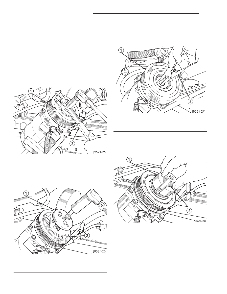
(4) Insert the two pins of the spanner wrench
(Special Tool C-4489) into the holes of the clutch
plate. Hold the clutch plate stationary and remove
the hex nut (Fig. 7).
(5) Remove the clutch plate with a puller (Special
Tool C-6461) (Fig. 8).
(6) Remove the compressor shaft key and the
clutch shims.
(7) Remove the external front housing snap ring
with snap ring pliers (Fig. 9).
(8) Install the lip of the rotor puller (Special Tool
C-6141-1) into the snap ring groove exposed in the
previous step, and install the shaft protector (Special
Tool C-6141-2) (Fig. 10).
Fig. 7 Clutch Nut Remove
1 – CLUTCH PLATE
2 – SPANNER
Fig. 8 Clutch Plate Remove
1 – CLUTCH PLATE PULLER
2 – CLUTCH PLATE
Fig. 9 External Snap Ring Remove
1 – PULLEY
2 – SNAP RING PLIERS
Fig. 10 Shaft Protector and Puller
1 – PULLER JAW
2 – SHAFT PROTECTOR
24 - 8
HEATING AND AIR CONDITIONING
XJ
REMOVAL AND INSTALLATION (Continued)
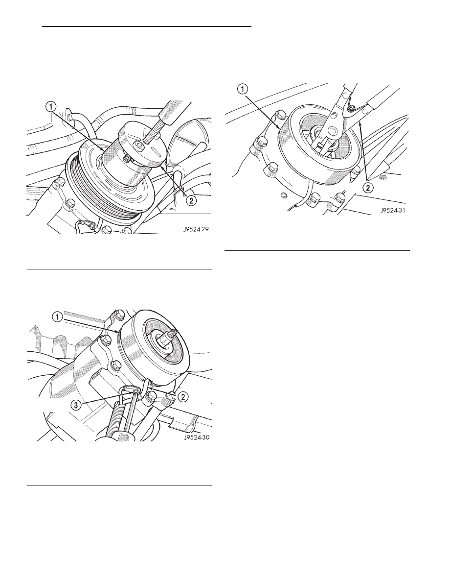
(9) Install the puller through-bolts (Special Tool
C-6461) through the puller flange and into the jaws
of the rotor puller and tighten (Fig. 11). Turn the
puller center bolt clockwise until the rotor pulley is
free.
(10) Remove the screw and retainer from the
clutch coil lead wire harness on the compressor front
housing (Fig. 12).
(11) Remove the snap ring from the compressor
hub and remove the clutch field coil (Fig. 13). Slide
the clutch field coil off of the compressor hub.
INSPECTION
Examine the friction surfaces of the clutch pulley
and the front plate for wear. The pulley and front
plate should be replaced if there is excessive wear or
scoring.
If the friction surfaces are oily, inspect the shaft
and nose area of the compressor for oil. Remove the
felt from the front cover. If the felt is saturated with
oil, the shaft seal is leaking and the compressor must
be replaced.
Check the clutch pulley bearing for roughness or
excessive leakage of grease. Replace the bearing, if
required.
INSTALLATION
(1) Install the clutch field coil and snap ring.
(2) Install the clutch coil lead wire harness retain-
ing clip on the compressor front housing and tighten
the retaining screw.
(3) Align the rotor assembly squarely on the front
compressor housing hub.
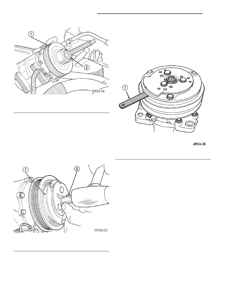
(4) Install the pulley bearing assembly with the
installer (Special Tool C-6871) (Fig. 14). Thread the
installer on the shaft, then turn the nut until the
pulley assembly is seated.
(5) Install the external front snap ring with snap
ring pliers. The bevel side of the snap ring must be
facing outward. Press the snap ring to make sure it
is properly seated in the groove.
Fig. 11 Install Puller Plate
1 – PULLER JAW
2 – PULLER
Fig. 12 Clutch Coil Lead Wire Harness
1 – COIL
2 – COIL WIRE
3 – RETAINER SCREW
Fig. 13 Clutch Field Coil Snap Ring Remove
1 – COIL
2 – SNAP RING PLIERS
XJ
HEATING AND AIR CONDITIONING
24 - 9
REMOVAL AND INSTALLATION (Continued)
CAUTION: If the snap ring is not fully seated in the
groove it will vibrate out, resulting in a clutch fail-
ure and severe damage to the front housing of the
compressor.
(6) Install the compressor shaft key and the origi-
nal clutch shims on the compressor shaft.
(7) Install the clutch plate with the driver (Special
Tool C-6463) (Fig. 15). Install the shaft hex nut and
tighten to 14.4 N·m (10.5 ft. lbs.).
(8) Check the clutch air gap with a feeler gauge
(Fig. 16). If the air gap does not meet the specifica-
tion, add or subtract shims as required. The air gap
specification is 0.41 to 0.79 millimeter (0.016 to 0.031
inch). If the air gap is not consistent around the cir-
cumference of the clutch, lightly pry up at the mini-
mum variations. Lightly tap down at the points of
maximum variation.
NOTE: The air gap is determined by the spacer
shims. When installing an original, or a new clutch
assembly, try the original shims first. When install-
ing a new clutch onto a compressor that previously
did not have a clutch, use 1.0, 0.50, and 0.13 milli-
meter (0.040, 0.020, and 0.005 inch) shims from the
clutch hardware package that is provided with the
new clutch.
(9) Reverse the remaining removal procedures to
complete the installation.
CLUTCH BREAK-IN
After a new compressor clutch has been installed,
cycle the compressor clutch approximately twenty
times (five seconds on, then five seconds off). During
this procedure, set the heater-A/C control to the
Recirculation Mode, the blower motor switch in the
highest speed position, and the engine speed at 1500
to 2000 rpm. This procedure (burnishing) will seat
the opposing friction surfaces and provide a higher
compressor clutch torque capability.
Fig. 14 Clutch Pulley Install
1 – PULLEY BEARING ASSEMBLY
2 – INSTALLER
Fig. 15 Clutch Plate Driver
1 – CLUTCH PLATE
2 – DRIVER
Fig. 16 Check Clutch Air Gap
1 – FEELER GAUGE
24 - 10
HEATING AND AIR CONDITIONING
XJ
REMOVAL AND INSTALLATION (Continued)
Document Outline
Wyszukiwarka
Podobne podstrony:
deon, 1c 2b 3b 4d 5a 6c 7d 8a 9b 10d 11b 12a 13b 14d 15c 16 b 17b 18d 19c 20b 21d 22d 23a 24a 25a 26
24a, Literatura pozwala możliwie najdokładniej poznać ten świat, zrozumieć i wyrazić
24a, Literatura pozwala możliwie najdokładniej poznać ten świat, zrozumieć i wyrazić
24a Metody badania materiałów półprzewodnikowych
poloznictwo 11 02 24a
SIMR-AN1-EGZ-2008-06-24a-rozw
Ćwicz. 24A, Studia, 1 rok, od Magdy, FIZYKA, Fizyka, Laborki z fizyki, moje laborki
24a
24A
24a, Politechnika Wrocławska, W-5 Wydział Elektryczny, Fizyka G2, fiza laborki, fiza kalit, fizyka l
24a UZDATNIANIE WODY DO CELÓW PRZEMYSŁOWYCH
24a ?danie zależności momentu obrotowego
exj 8q
24A
exj 6a
exj 6
exj 8qa
więcej podobnych podstron