
Exam Topics in this Chapter
58 IOS Specifics
CCIE.book Page 144 Thursday, March 6, 2003 9:25 AM

C
H
A
P
T
E
R
4
Cisco IOS Specifics and Security
This chapter covers the CCIE IOS Specifics blueprint. Unfortunately, the blueprint does not
detail the exact requirements, and IOS in general could mean the entire range of topics. We
cover topics that are actually possible topics in the written exam and common to the
Routing and Switching blueprint.
This chapter covers the following topics:
•
Cisco Hardware—This section covers the hardware components on a Cisco router,
namely the System Flash, nonvolatile RAM (NVRAM), and how files are saved to and
from a TFTP server.
•
show and debug Commands—This section covers the most common show and
debug commands used on Cisco routers to manage an IP network.
•
Password Recovery—This section covers how password recovery is completed on
Cisco IOS routers.
•
Basic Security on Cisco Routers—This section reviews some commands used to
ensure that Cisco routers are secured with basic passwords.
•
IP Access Lists— This section covers both standard and extended IP access lists and
their formats.
“Do I Know This Already?” Quiz
This assessment quiz’s purpose is to help you determine how to spend your limited study
time. If you can answer most or all these questions, you might want to skim the “Foundation
Topics” section and return to it later, as necessary. Review the “Foundation Summary”
section and answer the questions at the end of the chapter to ensure that you have a strong
grasp of the material covered. If you already intend to read the entire chapter, you do not
necessarily need to answer these questions now. If you find these assessment questions
difficult, you should read through the entire “Foundation Topics” section and review it until
you feel comfortable with your ability to answer all these and the Q & A questions at the
end of the chapter.
CCIE.book Page 145 Thursday, March 6, 2003 9:25 AM

146 Chapter 4: Cisco IOS Specifics and Security
Answers to these questions can be found in Appendix A, “Answers to Quiz Questions.”
1
What IOS command will display the System Flash?
a. show flash
b. show system flash
c. show memory
d. show process flash
2
The network administrator has forgotten the enable password and all passwords are
encrypted. What should the network administrator do to recover the password without
losing the current configuration?
a. Call the TAC and ask for a special back door password.
b. Call the TAC and raise a case to supply the engineering password.
c. Reboot the router, press the break key during the reload, and enter ROM mode and
change the configuration register.
d. Reboot the router, press the break key during the reload, enter ROM mode and change
the configuration register, and when the router reloads, remove the old configuration.
3
What is the enable password for the following router?
enable password Simon
a. More data required
b. Simon
c. simon or Simon
d. You cannot set the password to a name; it must also contain digits.
4
If the configuration register is set to 0x2101, where is the IOS image booted from?
a. slot0:
b. slot1:
c. Flash
d. ROM
e. TFTP server
CCIE.book Page 146 Thursday, March 6, 2003 9:25 AM

“Do I Know This Already?” Quiz 147
5
What IOS command will copy the running configuration to a TFTP server? (Select the
best two answers.)
a. copy running-config to tftp
b. write network
c. copy running-config tftp
d. write erase
6
What debug command allows an administrator to debug only packets from the network
131.108.0.0/16?
a. debug ip packet
b. terminal monitor
c. debug ip packet 1
d. access-list 1 permit 131.108.0.0
e. debug ip packet 1
f. access-list 1 permit 131.108.0.0 0.0.255.255
g. debug ip packet 1
h. access-list 1 permit 131.108.0.0 255.255.0.0
7
After entering debug ip packet, no messages appear on your Telnet session. What is the
likely cause?
a. OSPF routing is required.
b. The console port does not support debug output.
c. The terminal monitor command is required.
d. IP packets are not supported with the debug command.
8
To change the configuration register to 0x2141, what is the correct IOS command?
a. copy running-config register
b. configuration 0x2141
c. config 0x2141 register
d. config-register 0x2142
e. config-register 0x2141
CCIE.book Page 147 Thursday, March 6, 2003 9:25 AM

148 Chapter 4: Cisco IOS Specifics and Security
9
Where is the startup configuration stored on a Cisco router?
a. In the cam table
b. NVRAM
c. RAM
d. Flash
e. slot0:
10
Which of the following statements is true?
a. The enable secret command overrides the enable password command.
b. The enable command overrides the enable secret password command.
c. Enable passwords cannot be used when the secret password is used.
d. Both a and c are true.
11
A Cisco router has the following configuration:
line vty 0 4
login
What will happen when you Telnet to the router?
a. You will be prompted for the login password.
b. You will enter EXEC mode immediately.
c. You cannot access the router without the password set.
d. More configuration required.
12
A Cisco router has the following configuration:
line vty 0 4
no login
password cIscO
When a Telnet user tries to establish a remote Telnet session to this router, what will
happen?
a. You will be prompted for the login password cIscO.
b. You will enter EXEC mode immediately.
c. You cannot access the router without the password set.
d. More configuration required.
e. You will be prompted for the login password; password case does not matter.
CCIE.book Page 148 Thursday, March 6, 2003 9:25 AM

“Do I Know This Already?” Quiz 149
13
A Cisco router has the following configuration:
line vty 0 1
no login
password cisco
line vty 2 4
login
password ciSco
When a third Telnet session is established to a remote router with the preceding
configuration, what will happen?
a. You will be prompted for the login password, which is set to cisco.
b. You will be prompted for the login password, which is set to ciSco.
c. You will enter EXEC mode immediately.
d. You cannot access the router without the password set.
e. More configuration required.
14
Which of the following access lists will deny any IP packets sourced from network
131.108.1.0/24 and destined for network 131.108.2.0/24 and permit all other IP-based
traffic?
a. access-list 1 deny 131.108.1.0
b. access-list 1 deny 131.108.1.0 0.0.0.255
c. access-list 100 permit/deny ip 131.108.1.0 0.0.0.255 131.108.2.0 0.0.0.255
d. access-list 100 deny ip 131.108.1.0 0.0.0.255 131.108.2.0 0.0.0.255
e. access-list 100 permit ip any any
15
An administrator notices a router’s CPU utilization has jumped from 2 percent to 100
percent, and that a CCIE engineer was debugging. What IOS command can the network
administrator enter to stop all debugging output to the console and vty lines without
affecting users on the connected router?
a. no logging console debugging
b. undebug all
c. line vty 0 4
d. no terminal monitor
e. reload the router
CCIE.book Page 149 Thursday, March 6, 2003 9:25 AM

150 Chapter 4: Cisco IOS Specifics and Security
Foundation Topics
Cisco Hardware
Cisco routers consist of many hardware components. The main components of a Cisco router
include the following:
•
RAM
•
NVRAM
•
Flash
•
CPU
•
ROM
•
Configuration registers
•
Interfaces
Figure 4-1 illustrates the hardware components on Cisco routers.
Figure 4-1
Components of a Cisco Router
Each hardware component is vital for Cisco routers to operate properly. To help you prepare for
the CCIE Security written exam, the next few sections present the main concepts you need to
know about Cisco hardware components.
Random-Access Memory (RAM)
Read-Only
Memory (ROM)
Flash
Nonvolatile RAM
(NVRAM)
LAN, WAN,
Console, AUX Port
Router Interfaces
CCIE.book Page 150 Thursday, March 6, 2003 9:25 AM

Cisco Hardware 151
Random-Access Memory (RAM)
Routers use random-access memory (RAM) to store the current configuration file and other
important data collected by the router. This data includes the IP routing table and buffer
information. Buffers temporarily store packets before they are processed. All IOS processes,
such as routing algorithms (OSPF or BGP, for example), also run in RAM.
RAM information is lost if the router power cycles (when a router loses and regains power) or
is restarted by an administrator. To view a router’s current configuration, use the show running-
config IOS command. Before IOS version 10.3, administrators used the write terminal
command to show a router’s configuration. The write terminal command is still valid in
today’s IOS releases.
Cisco IOS is hardware-specific, and the image loaded on various router platforms varies from
platform to platform. For example, the image on a Cisco 4500 will not run on a Cisco 3600.
Also, IOS images contain certain features, such as IPX or DES encryption. For example, you
can load only IOS software that supports IP or IP plus DES encryption and so forth.
Please visit the following Cisco website for more details on Cisco IOS images and platform
requirements: www.cisco.com/warp/customer/130/choosing_ios.shtml.
Nonvolatile RAM (NVRAM)
Nonvolatile RAM (NVRAM) stores a copy of the router’s configuration file. The NVRAM
storage area is retained by the router in the event of a power cycle. When the router powers up
from a power cycle or a reboot (reload command), the IOS copies the stored configuration file
from the NVRAM to RAM. To view the configuration file stored in NVRAM, issue the show
startup-config command. In earlier versions of IOS (before version 10.3), the show config
command was used to view the configuration file stored in NVRAM. In IOS versions 11.0+,
both the show config and show startup-config commands will work.
System Flash
The System Flash is an erasable and programmable memory used to store the router’s IOS
image. Although Flash memory is always limited in size, it can contain multiple versions of
IOS. Therefore, you can delete, retrieve, and store new versions of IOS in the Flash memory
system. To view the Flash on a Cisco router, use the show flash IOS command. Example 4-1
displays the Flash filename on a router named R1.
CCIE.book Page 151 Thursday, March 6, 2003 9:25 AM

152 Chapter 4: Cisco IOS Specifics and Security
NOTE
On a high-performance router, such as Cisco 4500 series and 7500 series routers, you can make
the Flash system look like a file system and store many versions of IOS. The IOS command to
partition the System Flash is partition flash number-of-partition size-of-each-partition.
Example 4-1 shows that the IOS image, c2500-ajs40-l.12-17.bin, is currently stored on the
router’s on-board System Flash.
The Cisco 7500 series router provides the option of installing additional PCMCIA Flash
memory. If this additional memory is installed, the dir slot0: IOS command displays the IOS
image stored in slot0.
NOTE
The IOS image’s name conveys a lot of information, including the platform and feature sets.
For more information, go to www.cisco.com and search for “software naming convention.”
Central Processing Unit
The central processing unit (CPU) is the heart of a router, and every Cisco router has a CPU. A
CPU manages all the router’s processes, such as IP routing, and new routing entries, such as
remote IP networks learned through a dynamic routing protocol.
To view a CPU’s status, use the show process IOS command.
Example 4-2 shows a sample display taken from a Cisco IOS router.
Example 4-1
show flash Command
R1>show flash
System flash directory:
File Length Name/status
1 9558976 c2500-ajs40-l.12-17.bin
[9559040 bytes used, 7218176 available, 16777216 total]
16384K bytes of processor board System flash
Example 4-2
(Truncated) show process Command
R1>show process
CPU utilization for five seconds: 9%/7%; one minute: 9%;
five minutes: 10%
PID QTy PC Runtime (ms) Invoked uSecs Stacks TTY Proc
1 Csp 318F396 24456 1043 234 732/1000 0 Load Meter
2 M* 0 28 28 1000 3268/4000 0 EXEC
3 Lst 317D1FC 1304 175 5257 1724/2000 0 Check heap
...
c2500-ajs40-l.12-17.bin
CCIE.book Page 152 Thursday, March 6, 2003 9:25 AM

Cisco Hardware 153
The show process command displays the router utilization within the past five seconds, the past
one minute, as well as the average over the last five minutes. Details about specific processes
follow the CPU utilization statistics.
Read-Only Memory
Read-only memory (ROM) stores a scaled-down version of a router’s IOS in the event that the
Flash system becomes corrupted or no current IOS image is stored in Flash. ROM also contains
the bootstrap program (sometimes referred to as the rxboot image in Cisco documentation) and
a device’s power up diagnostics. You can perform only a software upgrade (that is, perform a
software image upgrade on the ROM) by replacing ROM chips because the ROM is not
programmable.
The bootstrap program enables you to isolate or rule out hardware issues. For example, you
might have a faulty Flash card and, subsequently, the router cannot boot the IOS image. The
power diagnostics program tests all the hardware interfaces on the router. ROM mode contains
a limited number of IOS commands, which enables the administrator or the Technical Assis-
tance Center (TAC) to help troubleshoot and ascertain any hardware or configuration issues on
a Cisco router. Cisco TAC is available 24 hours a day, seven days a week. You must pay Cisco
for this service and have a valid contract number to open any cases.
Unfortunately, not all Cisco routers have the same ROM code, so the commands might vary but
the principle remains the same. You can always issue the ? command in ROM mode to identify
the available commands used to troubleshoot a Cisco IOS-based router. Newer Cisco hardware
models now contain a new boot program stored in Boot Flash rather than in the ROM. The
program is a little more user-friendly. Menu-driven options are available to change the
configuration register, for example.
Example 4-3 provides all the available options on a Cisco 4000 router when the ? command is
used in ROM mode.
Example 4-3
? Command When in ROM Mode
> ?
? Types this display
$ Toggle cache state
B [filename] [TFTP Server IP address | TFTP Server Name]
Load and excutute system image from ROM or from TFTP server
C [address] Continue [optional address]
D /S M L V Deposit value V of size S into location L with
modifier M
E /S M L Examine location L with size S with modifier M
G [address] Begin execution
H Help for commands
I Initialize
K Displays Stack trace
L [filename] [TFTP Server IP address | TFTP Server Name]
continues
CCIE.book Page 153 Thursday, March 6, 2003 9:25 AM

154 Chapter 4: Cisco IOS Specifics and Security
The options in Example 4-3 include the ability to initialize a router with the i command after
you have finished ROM mode. ROM mode enables you to recover lost passwords by altering
the configuration registers (covered later in this chapter).
Configuration Registers
The configuration register is a 16-bit number that defines how a router operates on a power
cycle. These options include if the IOS will be loaded from Flash or ROM. Configuration
registers advise the CPU to load the configuration file from the NVRAM or to ignore the
configuration file stored in memory, for example. The default configuration register is displayed
as 0x2102. Table 4-1 displays the binary conversion from 0x2102.
Load system image from ROM or from TFTP server, but do not
begin execution
O Show software configuration register option settings
P Set break point
S Single step next instruction
T function Test device (? for help)
Table 4-1
0x2102 Binary Conversion
Bit Number
Value
15
0
14
0
13
1
12
0
11
0
10
0
9
0
8
1
7
0
6
0
5
0
4
0
3
0
2
0
1
1
0
0
Example 4-3
? Command When in ROM Mode (Continued)
CCIE.book Page 154 Thursday, March 6, 2003 9:25 AM

Cisco Hardware 155
The bits are numbered from right to left. In the preceding example, the value is displayed as
0x2102 (0010.0001.0000.0010). The function of the configuration register bits is determined
by their position, as follows:
•
Bits 0 through 3—Determines the boot option whether the router loads the IOS from the
Flash (binary value is 010) or from ROM (binary value is 000).
•
Bit 4—Reserved.
•
Bit 5—Reserved.
•
Bit 6—Tells the router to load the configuration from NVRAM if set to 1 and to ignore
the NVRAM if set to 0.
•
Bit 7— Referred to as the OEM (OEM = original equipment manufacturer) bit in Cisco
documentation and is not used.
•
Bit 8—Specifies whether to enter ROM mode without power cycling the router. If bit 8 is
set to 1 and the break key is issued while the router is up and running normally, the router
will go into ROM mode. This is a dangerous scenario because if this occurs, your router
immediately stops functioning.
•
Bit 9—Reserved.
•
Bit 10—Specifies the broadcast address to use, where 1 equals the use of all 0s for
broadcast at boot (in conjunction with bit 14). Bit 10 interacts with bit 14.
•
Bits 11 and 12—Set the console port’s baud rate. For example, if bits 11 and 12 are set to
00, the baud rate is 9600 bps. A baud rate of 4800 bps can be set when these bits are set
to 01. 10 sets the baud rate to 2400 bps, and 11 sets the baud rate to 1200 bps.
•
Bit 13—Tells the router to boot from ROM if the Flash cannot boot from a network, such
as a TFTP server. If bit 13 is set to 0 and no IOS is found, the router will hang. If bit 13 is
set to 1 and no IOS is found, the router boots from ROM.
•
Bit 14—Interacts with Bit 10 to define broadcast address.
•
Bit 15—Specifies to enable diagnostics display on startup and ignore the NVRAM.
To view the current configuration register, use the show version IOS command.
Example 4-4 displays the configuration register of a router, R1.
Example 4-4
(Truncated) show version Command
R1>show version
Cisco Internetwork Operating System Software
IOS (tm) 2500 Software (C2500-AJS40-L), Version 11.2(17)
, RELEASE SOFTWARE (fc1)
Copyright (c) 1986-1999 by Cisco Systems, Inc.
Compiled Tue 05-Jan-99 13:27 by ashah
Image text-base: 0x030481E0, data-base: 0x00001000
ROM: System Bootstrap, Version 5.2(8a), RELEASE SOFTWARE
continues
CCIE.book Page 155 Thursday, March 6, 2003 9:25 AM

156 Chapter 4: Cisco IOS Specifics and Security
The output from Example 4-4 displays the configuration register as 0x2102. The show version
command also displays other useful router information, such as the router’s uptime, the IOS
image in use, and the hardware configuration. To change the configuration register, use the
global configuration command, configure-register register-value. When a configuration
register is changed, use the show version command to ensure that the register has been changed
to the new value.
Table 4-2 displays common configuration register values you can use in day-to-day
troubleshooting of Cisco IOS routers.
Cisco Interfaces
Interfaces provide connections to a network. Interfaces include LANs, WANs, and management
ports (that is, console and auxiliary ports).
BOOTFLASH: 3000 Bootstrap Software (IGS-RXBOOT),
Version 10.2(8a), RELEASE SOFTWARE
R1 uptime is 6 days, 1 hour, 36 minutes
System restarted by reload
System image file is "flash:c2500-ajs40-l.112-17.bin", ..
..booted via flash
cisco 2520 (68030) processor (revision E) with 8192K/2048K byte
Processor board ID 02956210, with hardware revision 00000002
Bridging software.
SuperLAT software copyright 1990 by Meridian Technology Corp.
X.25 software, Version 2.0, NET2, BFE and GOSIP compliant.
TN3270 Emulation software.
Basic Rate ISDN software, Version 1.0.
1 Ethernet/IEEE 802.3 interface(s)
2 Serial network interface(s)
2 Low-speed serial(sync/async) network interface(s)
1 ISDN Basic Rate interface(s)
32K bytes of non-volatile configuration memory.
16384K bytes of processor board System flash (Read ONLY)
Configuration register is 0x2102
Table 4-2
Common Registers and Descriptions
Register Value
Description
0x2100
Boots the router using the system bootstrap found in ROM.
0x2102
Boots the router using Flash and NVRAM. This is the default setting.
0x2142
Boots the router using Flash and ignores NVRAM. This value is used to recover
passwords or modify configuration parameters.
Example 4-4
(Truncated) show version Command (Continued)
CCIE.book Page 156 Thursday, March 6, 2003 9:25 AM

Cisco Hardware 157
To view the current LAN or WAN interface, issue the show interface command. The show
interface command displays all LAN and WAN interfaces. To display information regarding
console or auxiliary ports, use the show line command. Figure 4-2 summarizes the available
IOS commands that administrators can use to view a router’s current configuration.
Figure 4-2
Interface IOS Commands
Now that you have reviewed Cisco routers’ hardware basics, it’s time to review how routers
operate. In addition to router operation, this chapter covers how administrators can manage
Cisco routers by saving and loading files to and from a TFTP server.
NOTE
Cisco routers can operate in a number of modes. Cisco defines them as follows:
•
ROM boot mode—When the router is in boot mode and loaded with a subset of the IOS
image, only a limited number of commands are available.
•
Configuration mode—Where you can make configuration changes. An example prompt
is Router1(config)#.
•
Interface configuration mode—Where you make configuration changes to interfaces
such as the Ethernet or Serial connections. Example prompt is Router1(config-if)#.
•
Initial configuration mode—When a router first boots up out of the box with no initial
configuration, you are prompted for basic system configuration details, such as name and
IP address assignment. The prompt looks like this:
Would you like to answer the initial configuration dialog? [yes/no]
Random-Access Memory (RAM)
show running-config
write terminal
show startup-config
show config
Read-Only
Memory (ROM)
Flash
Nonvolatile RAM
(NVRAM)
LAN, WAN,
Console, AUX Port
Router Interfaces
show flash
dir slot0.
show interfaces
CCIE.book Page 157 Thursday, March 6, 2003 9:25 AM

158 Chapter 4: Cisco IOS Specifics and Security
•
User EXEC mode—Basic IOS commands are permitted from the command-line
interface (CLI). An example prompt is R1>.
•
Privileged EXEC mode (also referred to as enabled mode)—Advance IOS commands
are permitted when the enable password or secret password is entered from the CLI. An
example prompt is R1#.
Saving and Loading Files
The configuration file can reside on the router’s NVRAM, RAM, or on a TFTP server. When a
router boots with the default configuration register (0x2102), the configuration file is copied
from NVRAM to RAM.
Network administrators typically save the configuration files to a TFTP server as a backup, in
case of a router failure.
To save a configuration file from RAM to NVRAM (after configuration changes are made), the
IOS command is copy running-config startup-config. The write terminal command will also
copy the running configuration to startup configuration. The write command is a legacy com-
mand from earlier releases of IOS still valid in today’s versions of IOS software.
Example 4-5 displays a successful configuration change on Ethernet 0/0, followed by a network
administrator in PRIV EXEC (privilege EXEC mode) mode saving the new configuration file
to NVRAM.
Table 4-3 summarizes the configuration file manipulation that can be performed on Cisco IOS
routers.
Example 4-5
Saving IOS Configurations Files
R1#configure terminal
Enter configuration commands, one per line. End with CNTL/Z.
R1(config)#interface ethernet 0/0
R1(config-if)#ip address 131.108.1.1 255.255.255.0
R1(config-if)#exit
R1#copy running-config startup-config
Destination filename [startup-config]?
Building configuration...
[OK]
R1#
CCIE.book Page 158 Thursday, March 6, 2003 9:25 AM

show and debug Commands 159
show and debug Commands
Cisco IOS CLI has an enormous amount of show and debug commands available to the
privileged EXEC user. This section covers the show and debug commands most often used to
manage Cisco IOS devices.
Router CLI
Cisco IOS routers allow network administrators access to a wide range of show and debug
commands. The show command displays various information about the router’s state of play,
such as the Ethernet collisions on a particular interface or a router’s configuration file. Only a
subset of show commands is available when in User EXEC mode. The full range is available
when in privilege EXEC mode (PRIV EXEC mode).
The debug command is a more advanced IOS command that allows the administrator to view
the router’s analyses of packets or buffering mechanisms and is used only to troubleshoot a
device or complete network. The debug command is very CPU-intensive.
show Commands
The best method to appreciate the use of show commands is to display sample output from a
Cisco IOS router.
Table 4-3
Cisco IOS File Manipulations
IOS Command
Meaning
copy running-config startup-config
Copies the configuration file from RAM to NVRAM.
write memory
Copies the running configuration to NVRAM. (Superseded by
the new command, copy running-config startup-config.)
copy startup-config running-config
Copies the configuration file from NVRAM to RAM.
write terminal
Displays the current configuration file in RAM. (Superseded
by the new command, show running-config.)
show config
Displays the current configuration file in NVRAM.
(Superseded by the new command, show startup-config.)
copy running-config tftp
Copies the configuration file stored in RAM to a TFTP server.
Can also be copied to an FTP or RCP server.
copy tftp running-config
Copies a configuration file from a TFTP server to the running
configuration.
CCIE.book Page 159 Thursday, March 6, 2003 9:25 AM

160 Chapter 4: Cisco IOS Specifics and Security
Example 4-6 displays a list of truncated show commands available from the CLI on a Cisco
router in PRIV EXEC mode.
Example 4-6
show Commands
R1#show ?
access-expression List access expression
access-lists List access lists
accounting Accounting data for active sessions
adjacency Adjacent nodes
aliases Display alias commands
arp ARP table
async Information on terminal lines used as router
interfaces
backup Backup status
bgp BGP information
bridge Bridge Forwarding/Filtering Database [verbose]
buffers Buffer pool statistics
caller Display information about dialup connections
cef Cisco Express Forwarding
class-map Show QoS Class Map
clock Display the system clock
configuration Contents of Non-Volatile memory
connection Show Connection
context Show context information
controllers Interface controller status
cops COPS information
crypto Encryption module
debugging State of each debugging option
derived-config Derived operating configuration
dhcp Dynamic Host Configuration Protocol status
diag Show diagnostic information for port
adapters/modules
dial-peer Dial Plan Mapping Table for, e.g. VoIP Peers
dialer Dialer parameters and statistics
dialplan Voice telephony dial plan
diffserv Differentiated services
dlsw Data Link Switching information
dnsix Shows Dnsix/DMDP information
docsis Show DOCSIS
drip DRiP DB
dspu Display DSPU information
dxi atm-dxi information
entry Queued terminal entries
environment Environmental monitor statistics
exception exception informations
file Show filesystem information
flash: display information about flash: file system
frame-relay Frame-Relay information
fras FRAS Information
fras-host FRAS Host Information
gateway Show status of gateway
history Display the session command history
CCIE.book Page 160 Thursday, March 6, 2003 9:25 AM

show and debug Commands 161
hosts IP domain-name, lookup style, nameservers, and host
table
html HTML helper commands
idb List of Hardware Interface Descriptor Blocks
interfaces Interface status and configuration
ip IP information (show ip route follows)
ipv6 IPv6 information
key Key information
line TTY line information
llc2 IBM LLC2 circuit information
lnm IBM LAN manager
local-ack Local Acknowledgement virtual circuits
location Display the system location
logging Show the contents of logging buffers
memory Memory statistics
mgcp Display Media Gateway Control Protocol information
microcode show configured microcode for downloadable hardware
modemcap Show Modem Capabilities database
mpoa MPOA show commands
ncia Native Client Interface Architecture
netbios-cache NetBIOS name cache contents
ntp Network time protocol
num-exp Number Expansion (Speed Dial) information
parser Display parser information
pas Port Adaptor Information
pci PCI Information
policy-map Show QoS Policy Map
ppp PPP parameters and statistics
printers Show LPD printer information
privilege Show current privilege level
processes Active process statistics
protocols Active network routing protocols
registry Function registry information
reload Scheduled reload information
rmon rmon statistics
route-map route-map information
running-config Current operating configuration
sessions Information about Telnet connections
sgbp SGBP group information
snmp snmp statistics
spanning-tree Spanning tree topology
srcp Display SRCP Protocol information
ssh Status of SSH server connections
ssl Show SSL command
stacks Process stack utilization
standby Hot standby protocol information
startup-config Contents of startup configuration
tcp Status of TCP connections
tech-support Show system information for Tech-Support
terminal Display terminal configuration parameters
traffic-shape traffic rate shaping configuration
continues
Example 4-6
show Commands (Continued)
CCIE.book Page 161 Thursday, March 6, 2003 9:25 AM

162 Chapter 4: Cisco IOS Specifics and Security
This section briefly covers the highlighted commands in Example 4-6.
Example 4-7 displays sample output from the most widely used IOS command, show ip route.
users Display information about terminal lines
version System hardware and software status
vlans Virtual LANs Information
vtemplate Virtual Template interface information
whoami Info on current tty line
Example 4-7
show ip route Command
R1#show ip route
Codes: C - connected, S - static, I - IGRP, R - RIP, M - mobile, B - BGP
D - EIGRP, EX - EIGRP external, O - OSPF, IA - OSPF inter area
N1 - OSPF NSSA external type 1, N2 - OSPF NSSA external type 2
E1 - OSPF external type 1, E2 - OSPF external type 2, E - EGP
i - IS-IS, L1 - IS-IS level-1, L2 - IS-IS level-2, ia - IS-IS inter area
* - candidate default, U - per-user static route, o - ODR
P - periodic downloaded static route
Gateway of last resort is not set
131.108.0.0/16 is variably subnetted, 3 subnets, 2 masks
C 131.108.255.0/30 is directly connected, Serial0/0
O 131.108.2.0/24 [110/400] via 131.108.255.2, 00:00:03, Serial0/0
C 131.108.1.0/24 is directly connected, Ethernet0/0
R1#show ip route ?
Hostname or A.B.C.D Network to display information about or hostname
bgp Border Gateway Protocol (BGP)
connected Connected
egp Exterior Gateway Protocol (EGP)
eigrp Enhanced Interior Gateway Routing Protocol (EIGRP)
igrp Interior Gateway Routing Protocol (IGRP)
isis ISO IS-IS
list IP Access list
mobile Mobile routes
odr On Demand stub Routes
ospf Open Shortest Path First (OSPF)
profile IP routing table profile
rip Routing Information Protocol (RIP)
static Static routes
summary Summary of all routes
supernets-only Show supernet entries only
vrf Display routes from a VPN Routing/Forwarding instance
| Output modifiers
<cr>
R1#show ip route ospf
131.108.0.0/16 is variably subnetted, 3 subnets, 2 masks
O 131.108.2.0/24 [110/400] via 131.108.255.2, 00:00:30, Serial0/0
R1#
Example 4-6
show Commands (Continued)
CCIE.book Page 162 Thursday, March 6, 2003 9:25 AM

show and debug Commands 163
Example 4-7 displays three IP routing entries. The more specific command, show ip route ospf,
only displays remote OSPF entries. Every IOS command can be used with the ? character to
display more options. In this case, the network administer used it to identify the ospf option and
then typed show ip route ospf to view only remote OSPF entries.
Example 4-8 displays the output from the show ip access-lists IOS command.
Example 4-8 enables the network administrator to quickly verify any defined access lists.
Example 4-8 includes two access lists numbered 1 and 100.
Use the show debugging command to display any debug commands in use. This verifies if any
debugging is currently enabled.
Example 4-9 displays the sample output when debug ip routing is enabled.
Currently, the router in Example 4-9 is enabled for debugging IP routing. To turn off the
debugging, apply the undebug all command, as shown in Example 4-9. This command ensures
all debug options are disabled. You can specify the exact debug option you want to disable with
the no options; for example, to disable the IP packet option, the IOS command is no debug ip
packet.
To display the hardware interfaces on the router, use the show interfaces command to explore
the physical and statistical state.
Example 4-8
show ip access-lists
R1#show ip access-lists ?
<1-199> Access list number
<1300-2699> Access list number (expanded range)
WORD Access list name
| Output modifiers
<cr>
R1#show ip access-lists
Standard IP access list 1
permit 131.108.0.0, wildcard bits 0.0.255.255
Extended IP access list 100
permit tcp any host 131.108.1.1 eq telnet
Example 4-9
show debugging Command
R1#show debugging
IP routing:
IP routing debugging is on
R1#undebug all
All possible debugging has been turned off
show debugging
CCIE.book Page 163 Thursday, March 6, 2003 9:25 AM

164 Chapter 4: Cisco IOS Specifics and Security
Example 4-10 displays the show interfaces command on a router named R1.
Example 4-10
show interfaces
R1#show interfaces
Ethernet0/0 is up, line protocol is up --physical status
Hardware is AmdP2, address is 0002.b9ad.5ae0 (bia 0002.b9ad.5ae0)
Internet address is 131.108.1.1/24
MTU 1500 bytes, BW 10000 Kbit, DLY 1000 usec,
reliability 255/255, txload 1/255, rxload 1/255
Encapsulation ARPA, loopback not set
Keepalive set (10 sec)
ARP type: ARPA, ARP Timeout 04:00:00
Last input 00:00:00, output 00:00:01, output hang never
Last clearing of "show interface" counters 00:00:05
Queueing strategy: fifo
Output queue 0/40, 0 drops; input queue 0/75, 0 drops
5 minute input rate 0 bits/sec, 0 packets/sec
5 minute output rate 0 bits/sec, 0 packets/sec
1 packets input, 366 bytes, 0 no buffer
Received 1 broadcasts, 0 runts, 0 giants, 0 throttles
0 input errors, 0 CRC, 0 frame, 0 overrun, 0 ignored
0 input packets with dribble condition detected
3 packets output, 202 bytes, 0 underruns(0/0/0)
0 output errors, 0 collisions, 0 interface resets
0 babbles, 0 late collision, 0 deferred
0 lost carrier, 0 no carrier
0 output buffer failures, 0 output buffers swapped out
Serial0/0 is up, line protocol is up
Hardware is PowerQUICC Serial
Internet address is 131.108.255.1/30
MTU 1500 bytes, BW 256 Kbit, DLY 20000 usec,
reliability 255/255, txload 1/255, rxload 1/255
Encapsulation FRAME-RELAY, loopback not set
Keepalive set (10 sec)
LMI enq sent 0, LMI stat recvd 0, LMI upd recvd 0, DTE LMI up
LMI enq recvd 0, LMI stat sent 0, LMI upd sent 0
LMI DLCI 0 LMI type is ANSI Annex D frame relay DTE
Broadcast queue 0/64, broadcasts sent/dropped 1/0, interface broadcasts 1
Last input 00:00:02, output 00:00:00, output hang never
Last clearing of "show interface" counters 00:00:07
Input queue: 0/75/0/0 (size/max/drops/flushes); Total output drops: 0
Queueing strategy: weighted fair
Output queue: 0/1000/64/0 (size/max total/threshold/drops)
Conversations 0/1/256 (active/max active/max total)
Reserved Conversations 0/0 (allocated/max allocated)
Available Bandwidth 192 kilobits/sec
5 minute input rate 0 bits/sec, 0 packets/sec
5 minute output rate 0 bits/sec, 0 packets/sec
2 packets input, 86 bytes, 0 no buffer
CCIE.book Page 164 Thursday, March 6, 2003 9:25 AM

show and debug Commands 165
Example 4-10 displays a router with two Ethernet interfaces and one serial interface. Interface
Ethernet 0/0 is enabled and is currently running packets over the wire, while Ethernet 0/1 is not
enabled. Interface Serial 0/0 is configured for Frame Relay and the physical layer (Layer 1)
details are displayed. Other possible physical states are as follows:
Ethernet0/1 is up, line protocol is up—The Ethernet Interface is active, sending and
receiving Ethernet frames.
Ethernet0/1 is up, line protocol is down—The Ethernet Interface is cabled but no
keepalives are received, and no Ethernet frames are sent or received (possible cable fault).
Ethernet0/1 is administratively down, line protocol is down—Ethernet Interface is not
enabled administratively; typically an interface not configured as yet.
Ethernet 0/1 is down, line protocol is up—A physical condition is not possible, for
example.
Received 0 broadcasts, 0 runts, 0 giants, 0 throttles
0 input errors, 0 CRC, 0 frame, 0 overrun, 0 ignored, 0 abort
2 packets output, 86 bytes, 0 underruns
0 output errors, 0 collisions, 0 interface resets
0 output buffer failures, 0 output buffers swapped out
0 carrier transitions
DCD=up DSR=up DTR=up RTS=up CTS=up
Ethernet0/1 is administratively down, line protocol is down
Hardware is AmdP2, address is 0002.b9ad.5ae1 (bia 0002.b9ad.5ae1)
MTU 1500 bytes, BW 10000 Kbit, DLY 1000 usec,
reliability 255/255, txload 1/255, rxload 1/255
Encapsulation ARPA, loopback not set
Keepalive set (10 sec)
ARP type: ARPA, ARP Timeout 04:00:00
Last input never, output never, output hang never
Last clearing of "show interface" counters 00:00:10
Queueing strategy: fifo
Output queue 0/40, 0 drops; input queue 0/75, 0 drops
5 minute input rate 0 bits/sec, 0 packets/sec
5 minute output rate 0 bits/sec, 0 packets/sec
0 packets input, 0 bytes, 0 no buffer
Received 0 broadcasts, 0 runts, 0 giants, 0 throttles
0 input errors, 0 CRC, 0 frame, 0 overrun, 0 ignored
0 input packets with dribble condition detected
0 packets output, 0 bytes, 0 underruns(0/0/0)
0 output errors, 0 collisions, 0 interface resets
0 babbles, 0 late collision, 0 deferred
0 lost carrier, 0 no carrier
0 output buffer failures, 0 output buffers swapped out
Example 4-10
show interfaces (Continued)
CCIE.book Page 165 Thursday, March 6, 2003 9:25 AM

166 Chapter 4: Cisco IOS Specifics and Security
To display the system log (syslog), use the show logging command. Example 4-11 displays a
sample output taken from a router name R1.
Example 4-11 shows that 27 message have been logged and the logging level is debugging,
which entails the following log message types:
•
Emergencies—System is unusable (severity = 0)
•
Alerts—Immediate action needed (severity = 1)
•
Critical—Critical conditions (severity = 2)
•
Errors—Error conditions (severity = 3)
•
Warnings—Warning conditions (severity = 4)
•
Notifications—Normal but significant conditions (severity = 5)
•
Informational—Informational messages (severity = 6)
•
Debugging—Debugging messages (severity = 7)
Two messages have also been displayed on the terminal: the first message is a configuration
change, and the second appears when a PRIV EXEC user cleared the counters on all the
interfaces.
The show route-map command displays any policy route maps configured. Policy route maps
override routing decisions on Cisco routers. Route maps basically allow an administrator to
access the route manipulation.
The show version command displays the system’s hardware configuration, the software
version, the names and sources of configuration files, and the boot images. Issue the show
version EXEC command to accomplish this.
Example 4-12 displays a sample output.
Example 4-11
show logging Command
R1#show logging
Syslog logging: enabled (0 messages dropped, 0 messages rate-limited, 0 flushes,
0 overruns)
Console logging: level debugging, 27 messages logged
Monitor logging: level debugging, 0 messages logged
Buffer logging: level debugging, 1 messages logged
Logging Exception size (4096 bytes)
Trap logging: level debugging, 31 message lines logged
Log Buffer (60000 bytes):
2d20h: %SYS-5-CONFIG_I: Configured from console by console
2d20h: %CLEAR-5-COUNTERS: Clear counter on all interfaces by console
27 messages logged
debugging
CCIE.book Page 166 Thursday, March 6, 2003 9:25 AM

show and debug Commands 167
Example 4-12 displays a number of key hardware data about the router. For example, the IOS
software version is 12.2T, the router’s uptime is 2 days, 20 hours, 15 minutes, and the memory
installed on the router is 64 MB. There is 16 MB of System Flash, and the current configuration
register is 0x2102.
NOTE
The alias command creates a custom shortcut to IOS commands so the EXEC user does not
have to type the complete IOS command. For example, show ip route is already defined in IOS
with the shortcut sh ip ro (not an alias command but rather a shortcut command). You can
define your own alias with the global IOS command:
alias EXEC
alias-name IOS-command
View the predefined aliases with the following command:
Router#show aliases
EXEC mode aliases:
h help
lo logout
p ping
r resume
s show
u undebug
un undebug
w where
Example 4-12
show version Command on R1
R1#show version
Cisco Internetwork Operating System Software
IOS (tm) C2600 Software (C2600-IK8O3S-M), Version 12.2(2)T, RELEASE SOFTWARE (f
c1)
TAC Support: http://www.cisco.com/cgi-bin/ibld/view.pl?i=support
Copyright (c) 1986-2001 by cisco Systems, Inc.
Compiled Sat 02-Jun-01 15:47 by ccai
Image text-base: 0x80008088, data-base: 0x813455F8
ROM: System Bootstrap, Version 11.3(2)XA4, RELEASE SOFTWARE (fc1)
ROM: C2600 Software (C2600-IK8O3S-M), Version 12.2(2)T, RELEASE SOFTWARE (fc1)
R1 uptime is 2 days, 20 hours, 15 minutes
System returned to ROM by reload at 14:57:18 UTC Mon Mar 1 1993
System restarted at 10:00:02 UTC Mon Mar 1 1993
System image file is "flash:c2600-ik8o3s-mz.122-2.T.bin"
cisco 2611 (MPC860) processor (revision 0x203) with 61440K/4096K bytes of memory
Processor board ID JAD043000VK (1947766474)
M860 processor: part number 0, mask 49
Bridging software.
X.25 software, Version 3.0.0.
2 Ethernet/IEEE 802.3 interface(s)
32K bytes of non-volatile configuration memory.
16384K bytes of processor board System flash (Read/Write)
Configuration register is 0x2102
C2600-IK8O3S-M), Version 12.2(2)T
61440K/4096K
CCIE.book Page 167 Thursday, March 6, 2003 9:25 AM

168 Chapter 4: Cisco IOS Specifics and Security
For example, you could make the command ospf display only OSPF routes by issuing the
following command:
alias EXEC ospf show ip route ospf
Debugging Cisco Routers
The debug command is one of the best set of tools you will encounter on Cisco routers. The
debug command is available only from privilege mode.
Cisco IOS router’s debugging includes hardware and software to aid in troubleshooting internal
problems and problems with other hosts on the network. The debug privileged EXEC mode
commands start the console display of several classes of network events.
For debug output to display on a console port, you must ensure that debugging to the console
has not been disabled or sent to the logging buffer with the logging console debug command.
If you enable any debug commands through a console and no debug output is displayed, it
might be because logging has been disabled.
Check the running configuration for the line no logging debugging console, and remove this
line (by typing logging debugging console) to enable debug messages to be viewed by the
console port.
Remember to turn off console logging when you are done troubleshooting the problem. The
router will continue to send to the console even if nobody is there, tying up valuable CPU
resources.
On virtual lines (VTY lines), you must enable the terminal monitor command to view the
debug output. You use VTY lines when you telnet to a remote Cisco router.
NOTE
Refer to the Cisco IOS Debug Command Reference at the following URL for the most updated
debug command information:
www.cisco.com/univercd/cc/td/doc/product/software/ios122/122sup/122debug/index.htm.
When debugging data, you must also be aware of the switching method used by the router (for
example, fast or process switches) because the CPU will use the same method when sending
debug output to the console or vty line.
The ip route-cache IOS command with no additional keywords enables fast switching.
When debug ip packet flow is enabled, make sure you disable fast switching so you can
view packet-by-packet flow through the router. Search the Cisco website for the keywords
“Process” and “fast switching” for more details on switching methods. The following URL
provides quality information on switching methods available on Cisco 7200 routers:
www.cisco.com/en/US/customer/products/sw/iosswrel/ps1831/products_configuration_
guide_chapter09186a00800ca6c7.html#xtocid6.
CCIE.book Page 168 Thursday, March 6, 2003 9:25 AM

show and debug Commands 169
Table 4-4 displays the debug commands and the system debug message feature.
Example 4-13 displays the list of debug command options covered in this section.
Table 4-4
debug Command Summary
IOS Command
Purpose
show debugging
Displays the state of each debugging option
debug ?
Displays a list and brief description of all the debug command
options
debug command
Begins message logging for the specified debug command
no debug command (or undebug all)
Turns message logging off for the specified debug command
or turns off all debug messages with the undebug all
command
Example 4-13
debug Command Options
R1#debug ?
all Enable all debugging
ip IP information
list Set interface or/and access list for the next debug
command
R1#debug ip ?
audit IDS audit events
auth-proxy Authentication proxy debug
bgp BGP information
cache IP cache operations
cef IP CEF operations
cgmp CGMP protocol activity
dhcp Dynamic Host Configuration Protocol
drp Director response protocol
dvmrp DVMRP protocol activity
egp EGP information
eigrp IP-EIGRP information
error IP error debugging
flow IP Flow switching operations
ftp FTP dialogue
html HTML connections
http HTTP connections
icmp ICMP transactions
igmp IGMP protocol activity
igrp IGRP information
inspect Stateful inspection events
interface IP interface configuration changes
mbgp MBGP information
mcache IP multicast cache operations
mhbeat IP multicast heartbeat monitoring
mobile IP Mobility
continues
CCIE.book Page 169 Thursday, March 6, 2003 9:25 AM

170 Chapter 4: Cisco IOS Specifics and Security
This section covers the debug commands highlighted in Example 4-13.
CAUTION
The CPU system on Cisco routers gives the highest priority to debugging output. For this
reason, debugging commands should be turned on only for troubleshooting specific problems
or during troubleshooting sessions with technical support personnel. Excessive debugging
output can render the system inoperable.
Try to use the most specific debug command possible to reduce the load on the CPU. For
example, the debug all command will surely disable a router. You should use only the debug
all command in a lab environment.
Typically, the console port is used for debugging major faults because the CPU places
debugging messages to the console port as the highest priority. Sometimes, debugging
messages can overwhelm a network administrator’s ability to monitor the router, and the IOS
command, logging synchronous, can limit the messages to the console.
mpacket IP multicast packet debugging
mrm IP Multicast Routing Monitor
mrouting IP multicast routing table activity
msdp Multicast Source Discovery Protocol (MSDP)
mtag IP multicast tagswitching activity
nat NAT events
nbar StILE - traffic classification Engine
ospf OSPF information
packet General IP debugging and IPSO security transactions
peer IP peer address activity
pim PIM protocol activity
policy Policy routing
postoffice PostOffice audit events
rgmp RGMP protocol activity
rip RIP protocol transactions
routing Routing table events
rsvp RSVP protocol activity
rtp RTP information
scp Secure Copy
sd Session Directory (SD)
security IP security options
socket Socket event
ssh Incoming ssh connections
tcp TCP information
tempacl IP temporary ACL
trigger-authentication Trigger authentication
udp UDP based transactions
urd URL RenDezvous (URD)
wccp WCCP information
Example 4-13
debug Command Options (Continued)
CCIE.book Page 170 Thursday, March 6, 2003 9:25 AM

show and debug Commands 171
When synchronous logging of unsolicited messages and debug output is turned on (the line
console is configured with the logging synchronous IOS command), unsolicited Cisco IOS
Software output is displayed on the console or printed after solicited Cisco IOS Software output
is displayed or printed. Unsolicited messages and debug output is displayed on the console
after the prompt for user input is returned. This keeps unsolicited messages and debug output
from being interspersed with solicited software output and prompts. After the unsolicited
messages are displayed, the console displays the user prompt again. The IOS commands
logging trap can be used to limit the logging of error messages sent to syslog servers to only
those messages at the specified level (levels range from 0 to 7). The lowest level is 7 (debugging
messages, greatest level of messages, as level 7 encompasses all levels possible from 0 to 7),
and the highest level is 0, or emergencies (system is unusable).
The debug all command turns on all possible debug options available to a Cisco router. This
will crash any router in a busy IP network, so we strongly recommended that you never apply
this command in a working network environment.
Example 4-14 displays the options when enabling IP packets through a Cisco router.
You can define an access list so that only packets that satisfy the access list are sent through to
the console or vty line.
Figure 4-3 displays a typical example where Simon, a user on one Ethernet (Ethernet 0/0), is
advising you that packets from users on Ethernet 0/1 (Melanie’s PC) are not reaching each
other. To view the routing packet flow through Router R1, you can debug the IP packets and use
a standard access list or an extended one (access lists are covered later in this chapter).
To view the IP packet flow and ensure that you view only packets from Melanie’s PC to Simon’s
PC, you can define an extended access list matching the source address, 131.108.2.100
(Melanie’s PC), to the destination address, 131.108.1.100 (Simon’s PC).
Example 4-14
debug ip packet ?
R1#debug ip packet ?
<1-199> Access list
<1300-2699> Access list (expanded range)
detail Print more debugging detail
<cr>
CCIE.book Page 171 Thursday, March 6, 2003 9:25 AM

172 Chapter 4: Cisco IOS Specifics and Security
Figure 4-3
IP Data Flow from One Segment to Another
Example 4-15 displays the debug command configuration on Router R1.
Applying the exact debug command for only traffic generated from one device to another
ensures that the router is not using too many CPU cycles to generate the debug output to the
console. When a ping request is sent from Melanie’s PC to Simon’s PC, debug output displays
a successful ping request.
Example 4-16 displays the sample debug output matching access-list 100 when 5 ping packets
are sent.
Example 4-15
Enabling debug ip packet with Access-list 100
R1#config terminal
Enter configuration commands, one per line. End with CNTL/Z.
R1(config)#access-list 100 permit ip host 131.108.2.100 host 131.108.1.100
R1#debug ip packet ?
<1-199> Access list
<1300-2699> Access list (expanded range)
detail Print more debugging detail
<cr>
R1#debug ip packet 100 ?
detail Print more debugging detail
<cr>
R1#debug ip packet 100 detail
IP packet debugging is on (detailed) for access list 100
131.108.1.100/24
131.108.2.100/24
interface Ethernet0/0
ip address 131.108.1.1 255.255.255.0
interface Ethernet0/1
ip address 131.108.2.1 255.255.255.0
User Melanie
User Simon
E0/0
E0/1
R1
Users Report
No Packet Flow
Application Layer Errors
Application Layer Errors
CCIE.book Page 172 Thursday, March 6, 2003 9:25 AM

show and debug Commands 173
NOTE
When debugging with a specific IP access list, be sure to stop all debugging options with the
undebug all IOS command before removing IP access lists; Cisco IOS routers are prone to
failure if the access list is removed before the debugging options are disabled. For example, no
debug output will be captured and sent to the console if no access list is defined but referenced
by a debug command (for example, debug ip packet 100, when access-list 100 is not defined).
Also, remember that the default, deny not specifically permitted, is the default behavior for
Cisco IOS access lists. Make sure you permit only traffic for which you are interested in
viewing debug messages like the example shown in Figure 4-3.
Example 4-16
Ping Request
R1#ping 131.108.1.100
2d22h: IP: s=131.108.2.100 (local), d=131.108.1.100 (Ethernet0/0), len 100,
sending
2d22h: ICMP type=8, code=0
2d22h: IP: s=131.108.2.100 (Ethernet0/0), d=131.108.1.100 (Ethernet0/0),
len 100, rcvd 3
2d22h: ICMP type=8, code=0
2d22h: IP: s=131.108.2.100 (local), d=131.108.1.100 (Ethernet0/0), len 100,
sending
2d22h: ICMP type=8, code=0
2d22h: IP: s=131.108.2.100 (Ethernet0/0), d=131.108.1.100 (Ethernet0/0),
len 100, rcvd 3
2d22h: ICMP type=8, code=0
2d22h: IP: s=131.108.2.100 (local), d=131.108.1.100 (Ethernet0/0), len 100,
sending
2d22h: ICMP type=8, code=0
2d22h: IP: s=131.108.2.100 (Ethernet0/0), d=131.108.1.100 (Ethernet0/0),
len 100, rcvd 3
2d22h: ICMP type=8, code=0
2d22h: IP: s=131.108.2.100 (local), d=131.108.1.100 (Ethernet0/0), len 100,
sending
2d22h: ICMP type=8, code=0
2d22h: IP: s=131.108.2.100 (Ethernet0/0), d=131.108.1.100 (Ethernet0/0),
len 100, rcvd 3
2d22h: ICMP type=8, code=0
2d22h: IP: s=131.108.2.1 (local), d=131.108.1.1 (Ethernet0/0), len 100,
sending
2d22h: ICMP type=8, code=0
2d22h: IP: s=131.108.2.100 (Ethernet0/0), d=131.108.1.100 (Ethernet0/0),
len 100, rcvd 3
2d22h: ICMP type=8, code=0
s=131.108.2.100 (Ethernet0/0), d=131.108.1.100 (Ethernet0/0),
CCIE.book Page 173 Thursday, March 6, 2003 9:25 AM

174 Chapter 4: Cisco IOS Specifics and Security
The debug output demonstrates that five packets were successfully routed from Ethernet 0/1 to
Ethernet 0/0. Therefore, the network fault reported by the users points to an application error
rather than a network error.
Table 4-5 displays the meaning of the codes in Example 4-16.
NOTE
The detail option allows for further detail in the debug output.
Using the route cache is often called fast switching. The route cache allows outgoing packets to
be load-balanced on a per-destination basis, rather than on a per-packet basis.
NOTE
The output modifier | (pipe) is a great time saver. For example, the command, show running-
config | begin router ospf 100, shows only the running configuration starting from the router
ospf 100 part instead of the entire output.
Password Recovery
Sometimes, the Cisco-enable or secret password is unknown and you must use password
recovery to attain or change the enable/secret password.
Password recovery allows the network administrator to recover a lost or unknown password on
a Cisco router. For password recovery, an administrator must have physical access to the router
through the console or auxiliary port. When an EXEC user enters an incorrect enable password,
the user receives an error message similar to the message shown in Example 4-17; the password
entered is Cisco which is displayed as *****.
Table 4-5
debug ip packet 100 detail Explanation
Field
Meaning
IP:
Indicates an IP packet
s=131.108.2.100
(Melanie’s PC)
Indicates the packet’s source address
d=131.108.1.100
(Simon’s PC)
Indicates the packet’s destination address
ICMP type 8 code 0
Ping request
Len 100
The length of the IP packet (100 bytes)
CCIE.book Page 174 Thursday, March 6, 2003 9:25 AM

Password Recovery 175
When a user receives a % Bad passwords message, the user can neither access the advanced
command set (in this case, enable mode), nor make any configuration changes. Fortunately,
Cisco provides the following 10-step method to recover a lost password without losing
configuration files:
Step 1
Power cycle the router.
Step 2
Issue a Control Break or the Break key command on the application (for
Windows 2000, it is Control-Pause) to enter into boot ROM mode. The
Control Break key sequence must be entered within 60 seconds of the router
restarting after a power cycle.
Step 3
After you are in ROM mode, change the configuration register value to ignore
the startup configuration file that is stored in NVRAM. Use the o/r 0x2142
command.
Step 4
Allow the router to reboot by entering the i command.
Step 5
After the router has finished booting up without its startup configuration, look
at the show startup-config command output. If the password is encrypted,
move to Step 6, which requires you to enter the enable mode (type enable and
you will not be required to enter any password) and copy the startup
configuration to the running configuration with the copy startup-config
running-config command. Then, change the password. If the password is not
encrypted and the enable secret command is not used, simply document the
plain text password and go to Step 8.
Step 6
Copy the startup configuration to RAM.
Step 7
Enable all active interfaces.
Step 8
Change the configuration register to 0x2102 (default).
Step 9
Reload the router.
Step 10
Check the new password.
Example 4-17
Incorrect Password Error Message
R1>enable
Password: ******
Password: *****
Password: *****
% Bad passwords
R1>
CCIE.book Page 175 Thursday, March 6, 2003 9:25 AM

176 Chapter 4: Cisco IOS Specifics and Security
NOTE
These are the generic steps for password recovery on a Cisco router. Some commands and
steps might be slightly different depending on the hardware platform. Refer to the Password
Recovery Procedures Index (www.cisco.com/warp/public/474/) for more information on each
platform.
To review, look at an example. Assume you are directly connected to Router R1 and you do not
know the enable password. You power cycle the router and press the Control Break key (the Esc
key) to enter boot mode.
Example 4-18 shows the dialog displayed by the router after a break is issued.
As you can see in Example 4-18, the ? symbol can display all the available options. To view the
current configuration register, issue the e/s 2000002 command, which displays the value of the
configuration register. Example 4-19 displays the current configuration register.
Example 4-18
Password Recovery Dialog on a Cisco Router
System Bootstrap, Version 5.2(8a), RELEASE SOFTWARE
Copyright (c) 1986-1995 by cisco Systems
Abort at 0x10EA882 (PC)
!control break issued followed by ? to view help options
>>?
------------>control break issued followed by ? to view help options
$ Toggle cache state
B [filename] [TFTP Server IP address | TFTP Server Name]
Load and EXECute system image from ROM
or from TFTP server
C [address] Continue EXECution [optional address]
D /S M L V Deposit value V of size S into location L with
modifier M
E /S M L Examine location L with size S with modifier M
G [address] Begin EXECution
H Help for commands
I Initialize
K Stack trace
L [filename] [TFTP Server IP address | TFTP Server Name]
Load system image from ROM or from TFTP server,
but do not begin EXECution
O Show configuration register option settings
P Set the break point
S Single step next instruction
T function Test device (? for help)
CCIE.book Page 176 Thursday, March 6, 2003 9:25 AM

Password Recovery 177
The default value for the configuration register on Cisco IOS routers is 2102. For illustrative
purposes, change the register to 0x2142, which tells the IOS to ignore the configuration in
NVRAM.
The command to change the configuration register in Boot ROM mode is 0/r 0x2142 followed
by the initialize (i) command, which will reload the router. Example 4-20 displays the
configuration change and initializing of the router from boot ROM mode.
The i command reboots the router and ignores your startup configuration because the configu-
ration register has been set to 0x2142. The aim here is to change the password without losing
your original configuration. Example 4-21 shows a truncated display by the Cisco IOS after the
router is reloaded.
Example 4-19
e/s 200002 Command in Boot Rom Mode
>e/s 2000002
! This command will display the current configuration register
2000002: 2102
! Type q to quit
>
Example 4-20
Changing the Configuration Register to 0x2142
>0/r 0x2142
>i
Example 4-21
Dialog After Reload
System Bootstrap, Version 5.2(8a), RELEASE SOFTWARE
Copyright (c) 1986-1995 by Cisco Systems
2500 processor with 6144 Kbytes of main memory
F3: 9407656+151288+514640 at 0x3000060
Restricted Rights Legend
Cisco Internetwork Operating System Software
IOS (tm) 2500 Software (C2500-AJS40-L), Version 11.2(17)
Copyright (c) 1986-1999 by cisco Systems, Inc.
Compiled Tue 05-Jan-99 13:27 by ashah
Image text-base: 0x030481E0, data-base: 0x00001000
Basic Rate ISDN software, Version 1.0.
1 Ethernet/IEEE 802.3 interface(s)
2 Serial network interface(s)
2 Low-speed serial(sync/async) network interface(s)
1 ISDN Basic Rate interface(s)
32K bytes of non-volatile configuration memory.
16384K bytes of processor board System flash (Read ONLY)
continues
CCIE.book Page 177 Thursday, March 6, 2003 9:25 AM

178 Chapter 4: Cisco IOS Specifics and Security
Notice that the router reverts to the default configuration. Enter the enable command to enter
privilege EXEC mode. In this example, you will not be prompted for the enable password
because there isn’t one; by default, no enable password is configured when a Cisco IOS router
boots from the default configuration (no passwords are configured in this default state).
You can view the startup config by using the show startup-config command (or show config
in IOS versions predating version 10.3), as shown in Example 4-22.
As you can see in Example 4-22, the enable password is encrypted. In instances where the
password is not encrypted, you could view the password using the show startup-config
command. When a password is encrypted, you must copy the startup configuration to the
running configuration and change the password manually by using the following IOS
command:
copy startup-config running-config
At this point, you are still in privileged mode, so you can now enter global configuration mode
to change the password back to its original setting (cisco, in this instance).
Example 4-23 displays the password change in global configuration mode set to the new
password of cisco.
--- System Configuration Dialog ---
At any point you may enter a question mark '?' for help.
Use ctrl-c to abort configuration dialog at any prompt.
Default settings are in square brackets '[]'.
Would you like to enter the initial configuration dialog? [yes]:No
Press RETURN to get started!
......
Router>ena !(no password required or entered)
Router#
Example 4-22
show startup-config Command
Router#show startup-config
Using 1968 out of 32762 bytes
! Last configuration change at 16:35:50 UTC Tue May 18 2002
! NVRAM config last updated at 16:35:51 UTC Tue May 18 2002
version 2.2
service password-encryption
hostname R1
! Note there is no secret password either
enable password 7 05080F1C2243
...
Example 4-21
Dialog After Reload (Continued)
CCIE.book Page 178 Thursday, March 6, 2003 9:25 AM

Basic Security on Cisco Routers 179
You complete password recovery by changing the configuration register back to the default
value (0x2102).
NOTE
If a secret password is also configured, you must use the enable secret password IOS command
because the secret password overrides the enable password. Example 4-23 includes no secret
password, so you can use the enable password command.
When the Cisco IOS router reloads, it will load the new configuration file with the password set
to cisco.
Basic Security on Cisco Routers
You can access a Cisco router in a number of ways. You can physically access a router through
the console port, or you can access a router remotely through a modem via the auxiliary port.
You can also access a router through a network or virtual terminal ports (VTY lines), which
allow remote Telnet access.
If you do not have physical access to a router—either through a console port or an auxiliary port
via dialup—you can access a router through the software interface, called the virtual terminal
(also referred to as a VTY port). When you telnet to a router, you might be required to enter the
VTY password set by the network administrator. For example, on Router R1, the administrator
types R2’s remote address and tries to telnet to one of the VTY lines.
Example 4-24 provides the session dialog when a user telnets to the router with the IP address
131.108.1.2.
Example 4-23
Changing a Password and Setting the Configuration Registry Commands
hostname#copy startup-config running-config
Destination filename [running-config]?
2818 bytes copied in 1.475 secs (2818 bytes/sec)
R1#config terminal
R1(config)#enable password cisco
R1(config)#config-register 0x2102
R1(config)#exit
R1#reload
Example 4-24
Using a VTY Port to Establish a Telnet Connection
R1#Telnet 131.108.1.2
Trying 131.108.1.2 ... Open
User Access Verification
Password: xxxxx
R2>
CCIE.book Page 179 Thursday, March 6, 2003 9:25 AM

180 Chapter 4: Cisco IOS Specifics and Security
Cisco routers can have passwords set on all operation modes, including the console port,
privilege mode, and virtual terminal access. To set a console password to prevent unauthorized
console access to the router, issue the commands shown in Example 4-25.
NOTE
All passwords are case-sensitive.
To set the privilege mode password, you have two options: the enable and secret password. To
set these passwords, use the respective commands listed in Example 4-26.
The command to set an enable password is enable password password. You can also set a more
secure password, called a secret password, which is encrypted when viewing the configuration
with the enable secret password command.
The secret password IOS command overrides the enable password. Cisco IOS does not permit
you to configure the same password if you apply both commands.
In Example 4-26, the secret password will always be used. Now, issue the show running-config
command to display the configuration after entering the enable and secret passwords in
Example 4-26.
Example 4-27 displays the output from the show running-config IOS command after entering
enable and secret passwords.
Example 4-25
Setting a Console Password
R1(config)#line con 0
R1(config-line)#password cisco
!You can also set a password on the auxiliary port
R1(config)#line aux 0
R1(config-line)#password cisco
Example 4-26
Setting Enable and Secret Password
R1(config)#enable password cisco
R1(config)#enable secret ccie
Example 4-27
show running-config Command on R1
R1#show running-config
Building configuration
Current configuration:
!
version 12.2
CCIE.book Page 180 Thursday, March 6, 2003 9:25 AM

Basic Security on Cisco Routers 181
Example 4-27 shows that the secret password is encrypted (using Cisco’s proprietary algo-
rithm), while the enable password is readable. This setup enables you to hide secret passwords
when the configuration is viewed. If you want, you can also encrypt the enable password by
issuing the service password-encryption command, as displayed in Example 4-28. Cisco uses
the MD5 algorithm to hash the secret password. You cannot reverse engineer the hashed pass-
word (for example, $1$Aiy2$GGSCYdG57PdRiNg/.D.XI.).
The service password-encryption command encrypts all passwords issued to the router using
the MD5 encryption algorithm. Example 4-29 shows an example of how these passwords
appear when the configuration is viewed after all passwords have been encrypted.
Example 4-29 displays the show running-config command output after encrypting all
passwords.
NOTE
Note the digits, 5 and 7, before the encrypted passwords. The number 5 signifies that MD5 Hash
algorithm is used for encryption, whereas the number 7 signifies a weaker algorithm. You are
not expected to know this for the written exam, but it is valuable knowledge for troubleshooting
complex networks. In fact, a great network engineer is measured by his well-defined trouble-
shooting techniques, and not by how many CCIE lab exams he has passed.
!
hostname R1
!
enable secret 5 $1$Aiy2$GGSCYdG57PdRiNg/.D.XI.
enable password cisco
Example 4-28
service password-encryption Command
R1(config)#service password-encryption
Example 4-29
show running-config Command on R1 After Encrypting All Passwords
R1#show running-config
Building configuration...
Current configuration:
!
service password-encryption
version 11.2
hostname R1
!
enable secret 5 $1$Aiy2$GGSCYdG57PdRiNg/.D.XI.
enable password 7 0822455D0A16
Example 4-27
show running-config Command on R1 (Continued)
service password-encryption
CCIE.book Page 181 Thursday, March 6, 2003 9:25 AM

182 Chapter 4: Cisco IOS Specifics and Security
Notice in Example 4-29 that both the secret and enable passwords are encrypted. If you enable
the service password-encryption command in global configuration mode, all passwords will
be encrypted and will not be viewable when displaying the configuration on the Cisco router.
The final Cisco password you can set is the virtual terminal password. This password verifies
remote Telnet sessions to a router. Example 4-30 displays the commands necessary to set the
virtual terminal password on a Cisco router.
If you issue the no login command below the virtual terminal command (line vty 0 4), remote
Telnet users will not be asked to supply a password and will automatically enter EXEC mode.
Example 4-31 displays the Telnet session dialogue when the no login command is entered.
Keep in mind that the preceding setup is not a secure access method for a router network.
IP Access Lists
Standard and extended access lists filter IP traffic. An access list is basically a set of permit
or deny statements. Standard access lists control IP traffic based on the source address only.
Extended access lists can filter on source and destination addresses. Extended access lists can
also filter on specific protocols and port numbers. This section covers how a Cisco router
handles access lists.
Access Lists on Cisco Routers
By default, a Cisco router permits all IP and TCP traffic unless an access list is defined and
applied to the appropriate interface. Figure 4-4 illustrates the steps taken if an access list is
configured on a Cisco router.
Example 4-30
password Command to Set a Virtual Terminal Password to ccie
R4(config)#line vty 0 4
R4(config-line)#password ccie
Example 4-31
Dialogue Display When No Login Is Enabled
R1#telnet 1.1.1.1
Trying 1.1.1.1 ... Open
R2>
CCIE.book Page 182 Thursday, March 6, 2003 9:25 AM
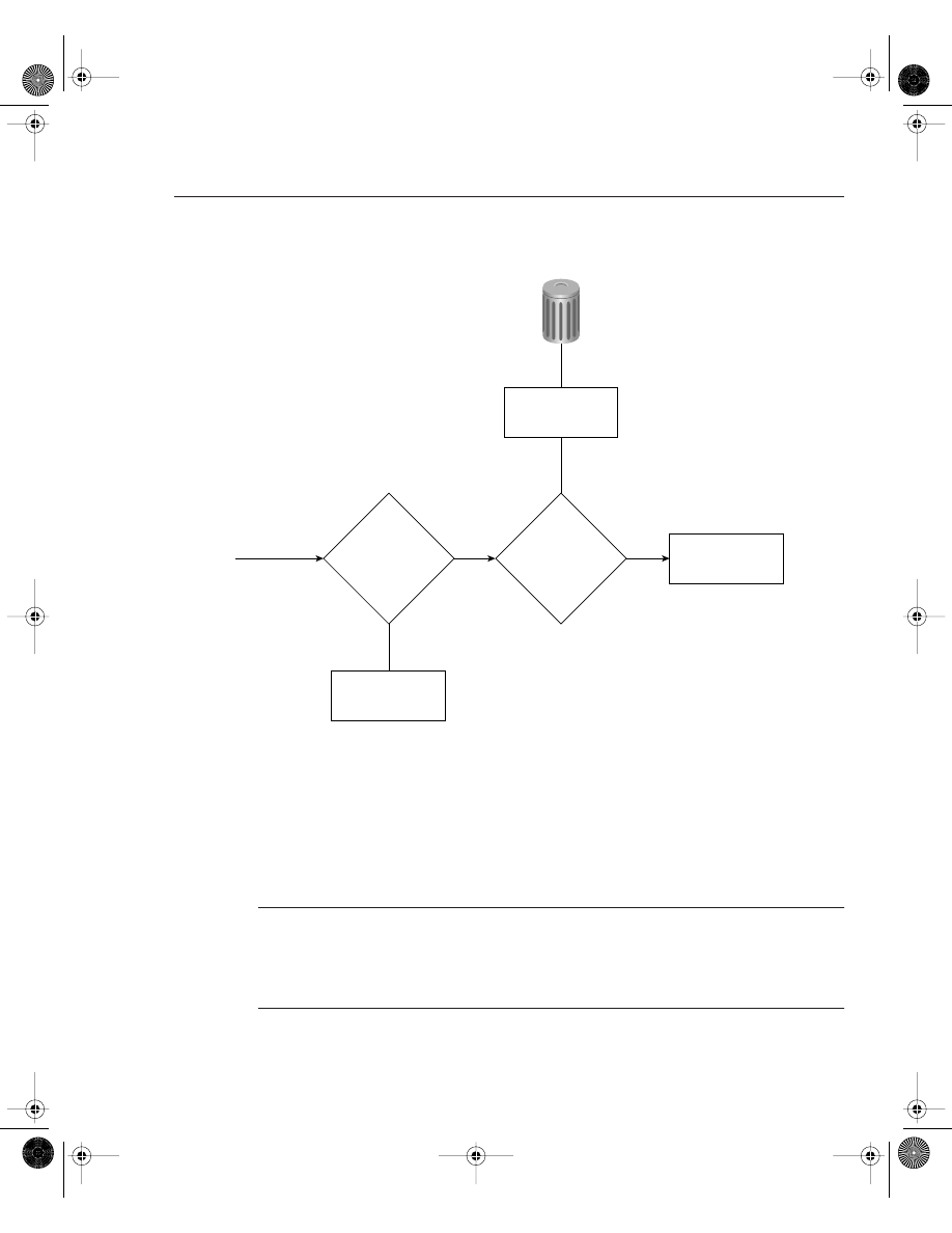
IP Access Lists 183
Figure 4-4
Access List Decision Taken by a Cisco Router
If an incoming IP packet is received on a router and no access list is defined, the packet is
forwarded to the IP routing software. If an access list is defined and applied, the packet is
checked against the access list, and the appropriate permit or deny action is taken. The default
action taken by any access list is to permit any explicitly defined statements and explicitly deny
everything else. You will not see the explicitly deny statement when you issue the show ip
access-lists because that is the default behavior.
NOTE
If the keyword out or in is not applied by the administrator when defining an IP filter on an
interface, the default action is to apply the filter on the outbound traffic.
Standard IP access lists range from 1 through 99 and 1300 through 1999.
Extended IP access lists range from 100 through 199 and 2000 through 2699.
Bit Bucket
Drop
Packet
Is
packet
permitted?
Access
list
configured?
Incoming
IP Packet
Process
IP Packet
Process
IP Packet
Yes
Yes
No
No
CCIE.book Page 183 Thursday, March 6, 2003 9:25 AM

184 Chapter 4: Cisco IOS Specifics and Security
Standard IP access lists filter on the source address only. The Cisco IOS syntax is as follows:
access-list
access-list-number {deny | permit} [source-address]
[
source-wildcard]
Table 4-6 describes the purpose of each field.
After creating the access list as described in Table 4-6, you must apply the access list to the
required interface using the following command:
ip access-group {
access-list-number | name} {in | out}
Table 4-7 describes the purpose of each field.
The wildcard mask previously mentioned in the access-list command matches the source
address. When the wildcard mask is set to binary 0, the corresponding bit field must match; if
it is set to binary 1, the router does not care to match any bit or it is an insignificant bit. For
example, the mask 0.0.255.255 means that the first two octets must match, but the last two
octets do not need to match—hence, the commonly used phrases care bits (0s) and don’t care
bits (1s).
Table 4-6
Standard IP access-list Command Syntax Description
Command Field
Description
access-list-number
A number from 1 through 99 that defines a standard access list number.
Versions of IOS 12.0 or later also have standard access lists ranging
from 1300-1999.
deny
IP packet is denied if a match is found.
permit
IP packet is permitted if it matches the criteria, as defined by the
administrator.
source-address
Source IP address or network. Any source address can be applied by
using the keyword any.
source-wildcard (optional)
Wildcard mask that is to be applied to the source address. This is an
inverse mask, which is further explained with a few examples later in
this section. The default is 0.0.0.0, which specifies an exact match.
Table 4-7
ip access-group Command Syntax Description
Command Field
Description
access-list-number
A number in the range from 1 through 99 and 1300 through 1999 that defines a
standard access list number.
name
If you are using named access lists, that name will be referenced here.
in
Keyword that designates the access list as an inbound packet filter.
out
Keyword that designates the access list as an outbound packet filter. This is the
default action.
CCIE.book Page 184 Thursday, March 6, 2003 9:25 AM

IP Access Lists 185
For further clarification, look at some examples of using access lists.
Suppose you have found a faulty NIC card with the address 141.108.1.99/24. You have been
asked to stop packets from being sent out Serial 0 on your router but to permit everyone else.
In this situation, you need to deny the host address 141.108.1.99 and permit all other host
devices. Example 4-32 displays the access list that fulfills this requirement.
Next, you would apply the access list to filter outbound (the keyword out is supplied) IP packets
on the Serial 0 interface. Example 4-33 applies the access list number 1 to the Serial interface
(outbound packets). You can be a little wiser and filter the incoming packets on the Ethernet
interface. This ensures that the packet is immediately dropped before it is processed by the CPU
for delivery over the serial interface. Both examples are displayed in Example 4-33.
Now look at a more complex example of using a standard access list. Suppose you have 16
networks ranging from 141.108.1.0 to 141.108.16.0, as shown in Figure 4-5.
You have assigned even subnets (2, 4, 6, 8, 10, 12, 14, and 16) to the Accounting department
and odd subnets (1, 3, 5, 7, 9, 11, 13, and 15) to the Sales department. You do not want the Sales
department to access the Internet, as shown in Figure 4-5. To solve this issue, you configure a
standard access list. Figure 4-5 displays a simple requirement to block all odd networks from
accessing the Internet.
You could configure the router to deny all the odd networks, but that would require many
configuration lines.
NOTE
Access lists are CPU-process-intensive because the router has to go through every entry in the
access list for each packet until a match is made. If you want to determine the actual effect an
access list has on your router, compare the CPU processes before and after activating an access
list. Remember to check on a regular basis to see the big picture.
Example 4-32
Access List Configuration
access-list 1 deny 141.108.1.99 0.0.0.0
access-list 1 permit 141.108.1.0 0.0.0.255
Example 4-33
Applying the Access-list
Interface Ethernet0
ip access-group 1 in
interface Serial 0
ip access-group 1 out
CCIE.book Page 185 Thursday, March 6, 2003 9:25 AM

186 Chapter 4: Cisco IOS Specifics and Security
Figure 4-5
Standard Access List Example
Instead, permit only even networks (2, 4, 6, 8, 10, 12, 14, and 16) with one IOS configuration
line. To accomplish this, convert all networks to binary to see if there is any pattern that you can
use in the wildcard mask.
Table 4-8 displays numbers 1 through 16 in both decimal and binary format.
Table 4-8
Example Calculation of Numbers in Binary
Decimal
Binary
1
00000001
2
00000010
3
00000011
4
00000100
5
00000101
6
00000110
7
00000111
8
00001000
Serial0/0
Internet
141.108.1.0
141.108.3.0
141.108.5.0
141.108.7.0
141.108.9.0
141.108.11.0
141.108.13.0
141.108.15.0
141.108.2.0
141.108.4.0
141.108.6.0
141.108.8.0
141.108.10.0
141.108.12.0
141.108.14.0
141.108.16.0
Odd
Networks
Block
Access to
Internet
Even
Networks
Sales
Department
Ethernet
segment
Accounting
Department
access-list permit 141.108.2.0 0.0.254.255
0
0
0
0
CCIE.book Page 186 Thursday, March 6, 2003 9:25 AM

IP Access Lists 187
Notice that odd networks always end in the binary value of 1, and even networks end with 0.
Therefore, you can apply your access lists to match on the even network and implicitly deny
everything else. Even numbers will always end in binary 0. You do not care about the first seven
bits, but you must have the last bit set to 0. The wildcard mask that applies this condition is
111111110 (1 is don’t care and 0 is must match; the first 7 bits are set to 1, and the last bit is
set to 0).
This converts to a decimal value of 254. The following access list will permit only even
networks:
access-list 1 permit 141.108.2.0 0.0.254.255
The preceding access list will match networks 2, 4, 6, 8, 10, 12, 14, and 16 in the third octet.
The default action is to deny everything else, so only even networks will be allowed, and odd
networks are blocked by default. Next, you would apply the access list to the outbound
interface. Example 4-34 describes the full configuration.
Extended Access Lists
Extended access lists range from 100 through 199 and 2000 through 2699. Alternatively, you
can use a named access list with IOS release 12.0 or later. As mentioned earlier in this chapter,
extended access lists can be applied to both source and destination addresses, as well as filter
protocol types and port numbers. Look at some examples of extended access lists that allow you
to filter several different types of traffic.
9
00001001
10
00001010
11
00001011
12
00001100
13
00001101
14
00001110
15
00001111
16
00010000
Example 4-34
Applying the Access List
Hostname R1
interface Serial0/0
ip access-group 1 out
access-list 1 permit 141.108.2.0 0.0.254.255
Table 4-8
Example Calculation of Numbers in Binary (Continued)
Decimal
Binary
0
0
0
0
CCIE.book Page 187 Thursday, March 6, 2003 9:25 AM

188 Chapter 4: Cisco IOS Specifics and Security
For Internet Control Message Protocol (ICMP), use the syntax shown in Example 4-35.
For Internet Group Management Protocol (IGMP), use the syntax shown in Example 4-36.
For TCP, use the syntax shown in Example 4-37.
For User Datagram Protocol (UDP), use the syntax shown in Example 4-38.
As you can see, extended access lists have a range of options to suit any requirement. The most
often used extended access list options are as follows:
•
access-list-number—Provides a number ranging from 100 through 199 that defines an
extended access list. Also numbers ranging from 2000 through 2699.
•
deny—Denies access if the conditions are matched.
•
permit—Permits access if the conditions are matched.
Example 4-35
Access List Syntax for ICMP Traffic
access-list
access-list-number [dynamic dynamic-name
[timeout minutes]] {deny | permit} icmp source source-wildcard
destination destination-wildcard [icmp-type [icmp-code]
[icmp-message] [precedence precedence] [tos tos] [log]
Example 4-36
Access List Syntax for IGMP Traffic
access-list access-list-number [dynamic dynamic-name
[timeout minutes]] {deny | permit} igmp source source-wildcard
destination destination-wildcard [igmp-type]
[precedence precedence] [tos tos] [log]
Example 4-37
Access List Syntax for TCP Traffic
access-list access-list-number [dynamic dynamic-name
[timeout minutes]] {deny | permit} tcp source source-wildcard
[operator port [port]] destination destination-wildcard
[operator port [port]] [established] [precedence precedence]
[tos tos] [log]
Example 4-38
Access List Syntax for UDP Traffic
access-list access-list-number [dynamic dynamic-name
[timeout minutes]] {deny | permit} udp source source-wildcard
[operator port [port]] destination destination-wildcard
[operator port [port]] [precedence precedence] [tos tos] [log]
CCIE.book Page 188 Thursday, March 6, 2003 9:25 AM

IP Access Lists 189
•
protocol—Specifies the protocol you are filtering. Some common options include eigrp,
gre, icmp, igmp, igrp, ip, ospf, tcp, and udp.
•
source—Specifies the source address.
•
source-wildcard—Specifies the wildcard mask.
•
destination—Identifies the destination network.
•
destination-wildcard—Identifies the destination mask.
You are expected to demonstrate your understanding of standard and extended access lists. You
are not expected to memorize the available options in an extended access list. The options are
provided in this chapter for your reference only. When constructing access lists, the built-in help
feature (?) is extremely useful.
Here are a few more complex examples of access lists.
Example 4-39 permits Domain Naming System (DNS) packets, ICMP echo and echo replies,
OSPF, and BGP packets. (BGP runs over TCP using port 179.)
In Example 4-39, the access list numbered 100 is not concerned with specific host addresses or
networks, but rather ranges of networks.
The any keyword is shorthand for 0.0.0.0 255.255.255.255, which means that the device’s
address is irrelevant. This address can be entered in shorthand as any. If any IP packet arrives
to the router and does not match the specified criteria, the packet is dropped.
The Cisco CD documentation provides additional quality examples of access lists. You should
take some time to study Cisco’s examples available on the CD and at www.cisco.com under the
technical documents link.
Access lists are difficult to manage because you cannot explicitly delete a specific line; you
must first remove the entire access list and re-enter the new access list with the correct order for
numbered access lists. For a large access list that might contain over 1000 lines of code, any
variations are completed on a TFTP server and copied to the startup configuration. I have
Example 4-39
Extended Access List Example
access-list 100 permit tcp any any eq smtp
! Permits Simple Mail Transfer Protocols
access-list 100 permit udp any any eq domain
! Permits DNS queries
access-list 100 permit icmp any any echo
! Permits ICMP ping requests
access-list 100 permit icmp any any echo-reply
! Permits ICMP replies
access 100 permit ospf any any
! Permits OSPF packets
access 100 permit tcp any any eq bgp
! Permits BGP to any device
CCIE.book Page 189 Thursday, March 6, 2003 9:25 AM

190 Chapter 4: Cisco IOS Specifics and Security
worked with some access lists that were 2500 lines in length and took over 5 minutes to load
on Cisco routers. On the other hand, named access-lists lists allow you to determine where in
the access list the new line will be placed. For more detail on named access-list, please visit,
www.cisco.com/en/US/customer/products/sw/iosswrel/ps1831/products_configuration_guide
_chapter09186a00800d9817.html.
It might be a likely scenario for the CCIE security lab exam so please ensure you are fully
comfortable with named and numbered access lists for the laboratory exam.
CCIE.book Page 190 Thursday, March 6, 2003 9:25 AM

Foundation Summary 191
Foundation Summary
The “Foundation Summary” is a condensed collection of material for a convenient review of
key concepts in this chapter. If you are already comfortable with the topics in this chapter and
decided to skip most of the “Foundation Topics” material, the “Foundation Summary” will help
you recall a few details. If you just read the “Foundation Topics” section, this review should
help further solidify some key facts. If you are doing your final preparation before the exam,
the “Foundation Summary” offers a convenient and quick final review.
Table 4-9
Cisco Device Commands and Information
Command
Description
show flash
Displays the content of the System Flash
Standard IP access list range
1-99, 1300-1999
Extended access list range
100-199, 2000-2699
copy running-config startup-config
IOS command to save running configuration from RAM to
NVRAM
copy startup-config running-config
IOS command to save running configuration from NVRAM to
RAM
0x2102
IOS syntax:
config-register value
0x2102 is the standard default configuration register, which is
a 16-bit number defining how the router loads
To ignore the startup configuration, use 0x2142
show version
Displays detailed information about IOS and hardware
configuration on a Cisco router
Table 4-10
Advanced Cisco Device Operation
IOS Command
Description
show debugging
Displays the current debug commands processed by the CPU
debug ?
Displays a list of available debug options
undebug all
Turns off all possible debugging commands
debug ip packet access-list
Allows debugging of specific network address without
burdening the router with every IP packet processed by the
CPU
CCIE.book Page 191 Thursday, March 6, 2003 9:25 AM

192 Chapter 4: Cisco IOS Specifics and Security
Table 4-11
Password Recovery Steps
Step
Description
1
Power cycle the router.
2
Issue a control break or the break key command on the application to enter into boot ROM
mode. The control break key sequence must be entered within 60 seconds of the router
restarting after a power cycle.
3
Once you are in ROM mode, change the configuration register value to ignore the startup
configuration file that is stored in NVRAM. Use the o/r 0x2142 command.
4
Allow the router to reboot by entering the i command.
5
After the router has finished booting up without its startup configuration, look at the show
startup-config command output. If the password is encrypted, move to Step 6, which
requires you to enter the enable mode (type enable and you will not be required to enter any
password) and copy the startup configuration to the running configuration with the copy
startup-config running-config command. Then, change the password.
If the password is not encrypted and the secret password is not used, you can simply read the
password. Skip Steps 6 and 7 and go to Step 8.
6
Copy the startup configuration to RAM.
7
Enable all active interfaces.
8
Change the configuration register to 0x2102 (default).
9
Reload router.
10
Check the new password.
Table 4-12
Basic Password Security
IOS Command
Description
enable password password
Defines the enable password (case-sensitive) to allow EXEC
user to Privilege mode where configuration changes can be
made. Typically not encrypted, and it is viewable when the
configuration is displayed.
enable secret password
Sets the secret password to enable EXEC user to Privilege
mode where configuration changes can be made. Overrides an
enable password and is encrypted by default.
service password-encryption
Encrypts all passwords on Cisco routers.
CCIE.book Page 192 Thursday, March 6, 2003 9:25 AM

Q & A 193
Q & A
The Q & A questions are designed to help you assess your readiness for the topics covered on
the CCIE Security written exam and those topics presented in this chapter. This format helps
you assess your retention of the material. A strong understanding of the answers to these ques-
tions will help you on the CCIE Security written exam. You can also look over the questions at
the beginning of the chapter again for additional review. Use the CD-ROM provided with this
book to take simulated exams, which draw from a database of over 300 multiple-choice ques-
tions—all different from those presented in the book.
Select the best answer. Answers to these questions can be found in Appendix A, “Answers to
Quiz Questions.”
1
Where is the running configuration stored on a Cisco router?
2
What IOS command displays the startup configuration?
3
What IOS command provides the following output?
System flash directory:
File Length Name/status
1 9558976 c2500-ajs40-l.12-17.bin
[9559040 bytes used, 7218176 available, 16777216 total]
16384K bytes of processor board System flash
4
What configuration register will enable a Cisco router to ignore the startup configuration?
CCIE.book Page 193 Thursday, March 6, 2003 9:25 AM

194 Chapter 4: Cisco IOS Specifics and Security
5
To copy the startup configuration to the running configuration, what IOS command or
commands are used?
6
What is the range for standard and extended IP access lists on Cisco IOS routers?
7
What command display the IP access lists configured on a Cisco router?
8
How do you disable all debug commands currently enabled on a Cisco router, assuming
you are not sure what debug commands are enabled?
9
What must you be very careful of when enabling any form of debugging on a Cisco router?
10
What are the required steps when performing password recovery on a Cisco router?
11
What is the enable password for the following configuration?
enable password CiscO
CCIE.book Page 194 Thursday, March 6, 2003 9:25 AM
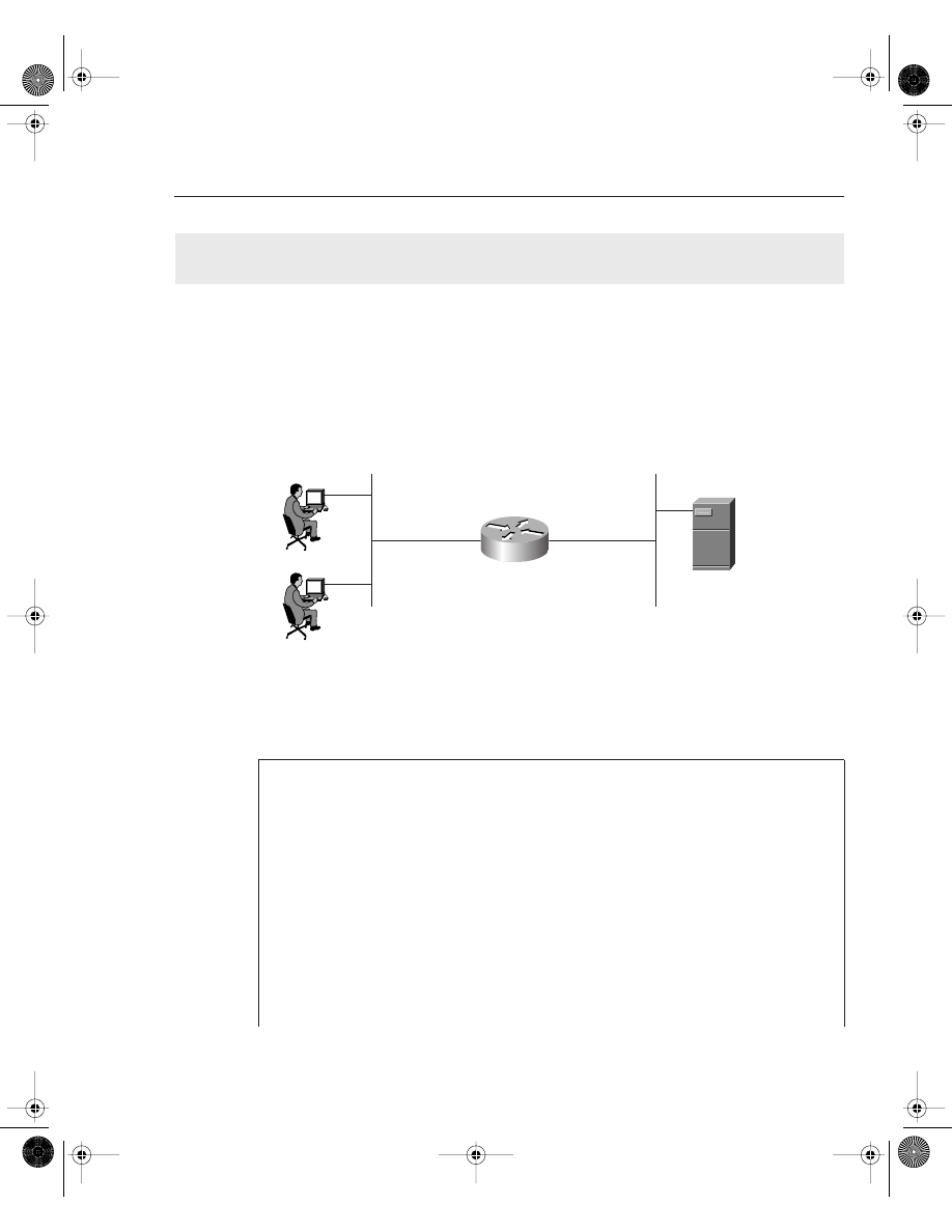
Scenario 4-1: Configuring Cisco Routers for Passwords and Access Lists 195
Scenario
Scenario 4-1: Configuring Cisco Routers for Passwords
and Access Lists
Figure 4-6 displays a simple one-router network with two Ethernet LAN interfaces connecting
users on subnet 131.108.1.0/24 to the server IP network, 131.108.2.0/24.
Figure 4-6
Scenario Physical Topology
Example 4-40 displays the working configuration file on R1 numbered from line 1 to 25.
Example 4-40
R1’s Full Configuration
1. version 12.2
2. no service password-encryption
3. hostname R1
4. no logging console debugging
5. enable secret 5 $1$TBUV$od27CrEfa4UVICBtwvqol/
6. enable password ciscO
7.interface Ethernet0/0
8. ip address 131.108.1.1 255.255.255.0
9.interface Ethernet0/1
10. ip address 131.108.2.1 255.255.255.0
11.no ip http server
12.access-list 1 permit 131.108.0.0 0.0.255.255
13.access-list 100 permit tcp any host 131.108.1.1 eq telnet
14.access-list 100 permit ip host 131.108.2.100 host 131.108.1.1
15.alias EXEC test show ip route ospf
16.alias EXEC eth0 show interface ethernet0/0
17.alias EXEC eth1 show interface ethernet0/1
continues
131.108.1.100/24
131.108.1.101/24
131.108.1.1/24
131.108.2.100/24
131.108.2.1/24
Ethernet0/0
Ethernet0/1
R1
CCIE.book Page 195 Thursday, March 6, 2003 9:25 AM

196 Chapter 4: Cisco IOS Specifics and Security
1
The network administrator enables the debug ip packet command on Router R1, but
no output is seen when connected to the console. IP traffic is following correctly from
Ethernet0/0 to Ethernet0/1. What is the likely problem? What IOS configuration change
is required to rectify the fault?
2
There are a number of configured aliases. What alias will display the Ethernet interface
statistics for the Ethernet interface labeled Ethernet0/1?
3
When the following command is entered at the privilege EXEC prompt, what will the
output be?
R1#eth0
4
What is the password of Router 1 that enables a network administrator to make
configuration changes?
5
What debug command can be used to debug IP packets’ source from the address
131.108.2.100 to the PC with the IP address of 131.108.1.100.
6
A user telnets to Router R1 and runs the debug command, debug ip packet.
IP data travels from the PC to the server but no output is displayed on the router.
What is the likely problem?
R2#R1
Trying 131.108.255.1 ... Open
R1>debug ip packet
^
% Invalid input detected at '^' marker.
R1>
7
What is the configuration register of the router in Figure 4-6?
8
What is the VTY password required for Telnet clients logging into R1?
9
What does access list 1 accomplish in line 12?
10
What Global IOS command would encrypt all passwords configured on R1 in Figure 4-6?
18.line con 0
19.EXEC-timeout 0 0
20.login
21.line aux 0
22.line vty 0 4
23.EXEC-timeout 0 0
24.no login
25.end
Example 4-40
R1’s Full Configuration (Continued)
CCIE.book Page 196 Thursday, March 6, 2003 9:25 AM

Scenario Answers 197
Scenario Answers
1
Line 4 in Example 4-39 has disabled the debug output from being visible. To enable
debug messages to be sent to the console port, the command logging console debugging
must be configured in global configuration mode. Alternatively, telneting to the router and
enabling the terminal monitor command via the VTY line enables the network
administrator to view the debug output.
2
Line 17 displays the alias, eth1, which is the command show interface ethernet0/1.
3
Line 16 defines an alias, eth0, which will be used as a shortcut to the show interface
ethernet0/0 command. This IOS command displays the statistics of interface Ethernet0/0.
4
Line 6 (enable password ciscO) defines the enable password as ciscO. However, because
a secret password exists on line 5, that is the password required to enter enable mode, and
because the secret password is encrypted, you cannot decipher the password.
5
Access list 100 defines an Access-list with the source address 131.108.2.100 to the
destination IP address 131.108.1.100. You can apply the debug command, debug ip
packet 100, with the optional keyword detail to view IP packets sent from the server to
the IP address 131.108.1.100.
6
The Telnet user must be in privilege EXEC mode and must enable the terminal monitor
command to ensure debug output is sent to the VTY line.
7
The configuration in Example 4-38 does not include a configuration register, so the default
register (0x2102) is enabled.
8
Line 24 configures the router for no VTY login, so there is no password; any Telnet users
will be directed to the router at the EXEC prompt level.
9
Access list 1 is not defined on any interface and can be used when debug ip packet is
turned on. Because it is a standard access list, it can be used to debug packets’ source from
network 131.108.0.0 to 131.108.255.255.
10
The Global IOS command, service password-encryption, encrypts all passwords,
including the enable and VTY password, if any.
CCIE.book Page 197 Thursday, March 6, 2003 9:25 AM
Wyszukiwarka
Podobne podstrony:
1SBC100122C0202 Ch04 Nieznany
CH04
Genomes3e ppt ch04
1587200708
1587200023ch11 ZOZMG2GYXP6IJSFE Nieznany
ch04
ch04
1587200678
ch04
ch04
CH04
Ch04 Templates
CH04
ai9 cib ch04 pentool
Essentials of Biology mad86161 ch04
Ch04 Solations Brigham 10th E
więcej podobnych podstron