
TABLE OF CONTENTS
Subject Page
Engine Cooling System . . . . . . . . . . . . . . . . . . . . . . . . . . . . . . . . . . . . . . . . 2
Radiator . . . . . . . . . . . . . . . . . . . . . . . . . . . . . . . . . . . . . . . . . . . . . . . . . . . 2
Coolant Recovery& Level Check . . . . . . . . . . . . . . . . . . . . . . . . . . . . . . . . . 5
Radiator Cap . . . . . . . . . . . . . . . . . . . . . . . . . . . . . . . . . . . . . . . . . . . . . . . . 4
Main Cooling Fan . . . . . . . . . . . . . . . . . . . . . . . . . . . . . . . . . . . . . . . . . . . . 5
Engine Coolant . . . . . . . . . . . . . . . . . . . . . . . . . . . . . . . . . . . . . . . . . . . . . . 6
ECM Controlled Function . . . . . . . . . . . . . . . . . . . . . . . . . . . . . . . . . . . . . . . 9
Water Valves . . . . . . . . . . . . . . . . . . . . . . . . . . . . . . . . . . . . . . . . . . . . . . . . 10
Heater Core . . . . . . . . . . . . . . . . . . . . . . . . . . . . . . . . . . . . . . . . . . . . . . . . . 11
Heater & Air Conditioning System Comparisons . . . . . . . . . . . . . . . . . . . . . 12
Theory of Heat & Refrigeration . . . . . . . . . . . . . . . . . . . . . . . . . . . . . . . . . . . 13
Air Conditioning (A/C) System . . . . . . . . . . . . . . . . . . . . . . . . . . . . . . . . . . . 22
Refrigerant . . . . . . . . . . . . . . . . . . . . . . . . . . . . . . . . . . . . . . . . . . . . . . . . . . 24
Adding Oil to the System . . . . . . . . . . . . . . . . . . . . . . . . . . . . . . . . . . . . . . . 25
Compressor . . . . . . . . . . . . . . . . . . . . . . . . . . . . . . . . . . . . . . . . . . . . . . . . 26
Compressor Clutch . . . . . . . . . . . . . . . . . . . . . . . . . . . . . . . . . . . . . . . . . . . 31
Condenser . . . . . . . . . . . . . . . . . . . . . . . . . . . . . . . . . . . . . . . . . . . . . . . . . 33
Auxiliary Fan . . . . . . . . . . . . . . . . . . . . . . . . . . . . . . . . . . . . . . . . . . . . . . . . 35
R-12 Receiver/Dryer . . . . . . . . . . . . . . . . . . . . . . . . . . . . . . . . . . . . . . . . . . 37
Repair Procedure . . . . . . . . . . . . . . . . . . . . . . . . . . . . . . . . . . . . . . . . . . . . 38
Proper Reading of the Sight Glass . . . . . . . . . . . . . . . . . . . . . . . . . . . . . . . . 39
R-134a Receiver/Dryer . . . . . . . . . . . . . . . . . . . . . . . . . . . . . . . . . . . . . . . . 41
Expansion Valve . . . . . . . . . . . . . . . . . . . . . . . . . . . . . . . . . . . . . . . . . . . . . 42
Evaporator . . . . . . . . . . . . . . . . . . . . . . . . . . . . . . . . . . . . . . . . . . . . . . . . . . 44
Blower Motor . . . . . . . . . . . . . . . . . . . . . . . . . . . . . . . . . . . . . . . . . . . . . . . . 46
Microfilters . . . . . . . . . . . . . . . . . . . . . . . . . . . . . . . . . . . . . . . . . . . . . . . . . . 47
Types of Refrigerants . . . . . . . . . . . . . . . . . . . . . . . . . . . . . . . . . . . . . . . . . . 49
Refrigerant Handling Certification Requirements . . . . . . . . . . . . . . . . . . . . . 55
Leak Detectors . . . . . . . . . . . . . . . . . . . . . . . . . . . . . . . . . . . . . . . . . . . . . . 59
Temperature Sensing Equipment . . . . . . . . . . . . . . . . . . . . . . . . . . . . . . . . . 60
Safety Precautions . . . . . . . . . . . . . . . . . . . . . . . . . . . . . . . . . . . . . . . . . . . . 62
Ambient Temperature/Relative Humidty Chart . . . . . . . . . . . . . . . . . . . . . . . 65
Non-Approved Air Conditioning Refrigerants . . . . . . . . . . . . . . . . . . . . . . . . 70
Verified System Malfunction Follow-up . . . . . . . . . . . . . . . . . . . . . . . . . . . . . 72
Basic Troubleshooting . . . . . . . . . . . . . . . . . . . . . . . . . . . . . . . . . . . . . . . . . 73
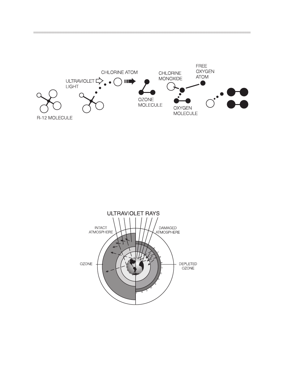
A serious environmental problem has been created by discharging R-12 refrigerant into
the atmosphere. CFC’s cause very long-term damage to the stratospheric ozone layer.
One molecule of R-12 can destroy many molecules of ozone. In the upper atmosphere,
ultraviolet light breaks off a chlorine atom from an R-12 molecule.
The chlorine attacks an ozone molecule, breaking it apart. An ordinary oxygen molecule
and a molecule of chlorine monoxide are formed.
A free oxygen atom breaks up the chlorine monoxide. The chlorine is then free to repeat
the process.
The ozone in the stratosphere blocks most of the ultraviolet-B radiation from the sun, thus
preventing it from damaging plants and animals. Without the protection of stratospheric
ozone, plants and animals are exposed to damaging levels of UV-B.
50
One CFC Molecule Destroys Many Ozone Molecules
Damage to Stratospheric Ozone Allows UV-B Penetration
R-134a
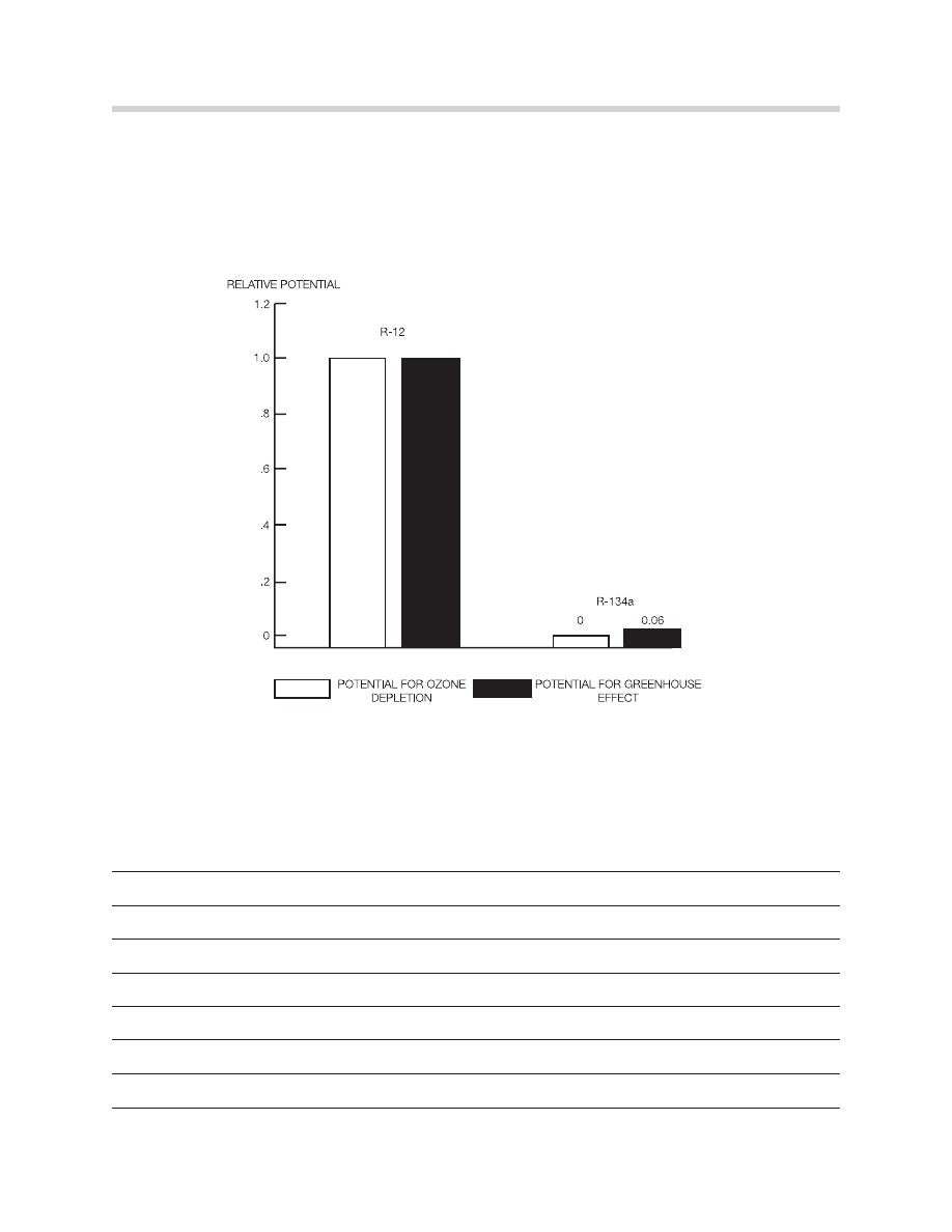
For this reason, a new refrigerant, R-134a, has been developed. It does not contain chlo-
rine (it’s a “hydrofluoro-carbon,” or “HFC”). It causes much less damage to stratospheric
ozone.
Despite the much lower risk of environmental damage, it’s still important to handle R-134a
responsibly. BMW technicians should do their part to maintain a safe environment for
future generations.
51
Environmental Compatibility of R-12 and R-134a

Characteristics of R-134a:
•
Very durable.
•
Transports heat very efficiently
•
Density, pressure, boiling point similar to R-12.
•
Extremely hygroscopic (absorbs water very readily).
•
Non-toxic, non-flammable; slight ether-like smell.
•
Contains no chlorine atoms; will not damage stratospheric ozone.
•
R-134a pressures tend to rise sooner and higher as temperature increases.
IDENTIFICATION OF R-12 AND R-134a CONTAINERS
Although R-12 and R-134a are similar in some ways, the refrigerants must never be mixed
or combined in any way.
52
PHYSICAL CHARACTERISTICS
Boiling Point (typical, sea level)
Density (at 68° F)
Latent Heat of Vaporization (at 32° F)
Saturation Vapor Pressure (at 194° F)
Molecular Size
R-12
R-134a
-22° F
-15° F
11 lb./gal.
10 lb./gal.
318 BTU/lb.
413 BTU/lb.
383 psi
467 psi
4.4 Å
4.2 Å
CONTAINERS
Color
Fittings
R-12
R-134a
Yellow
Light Blue
7/16” -20
1/2” -16 Acme
or 1/4” Flare-Type
BASIC SYSTEM DIFFERENCES: R-12 vs R-134a
•
R-134a pressures are higher than R-12, as temperature increases.
•
Compressor oils:
— R-12 systems use mineral oil.
— 134a systems use PAG oil.
•
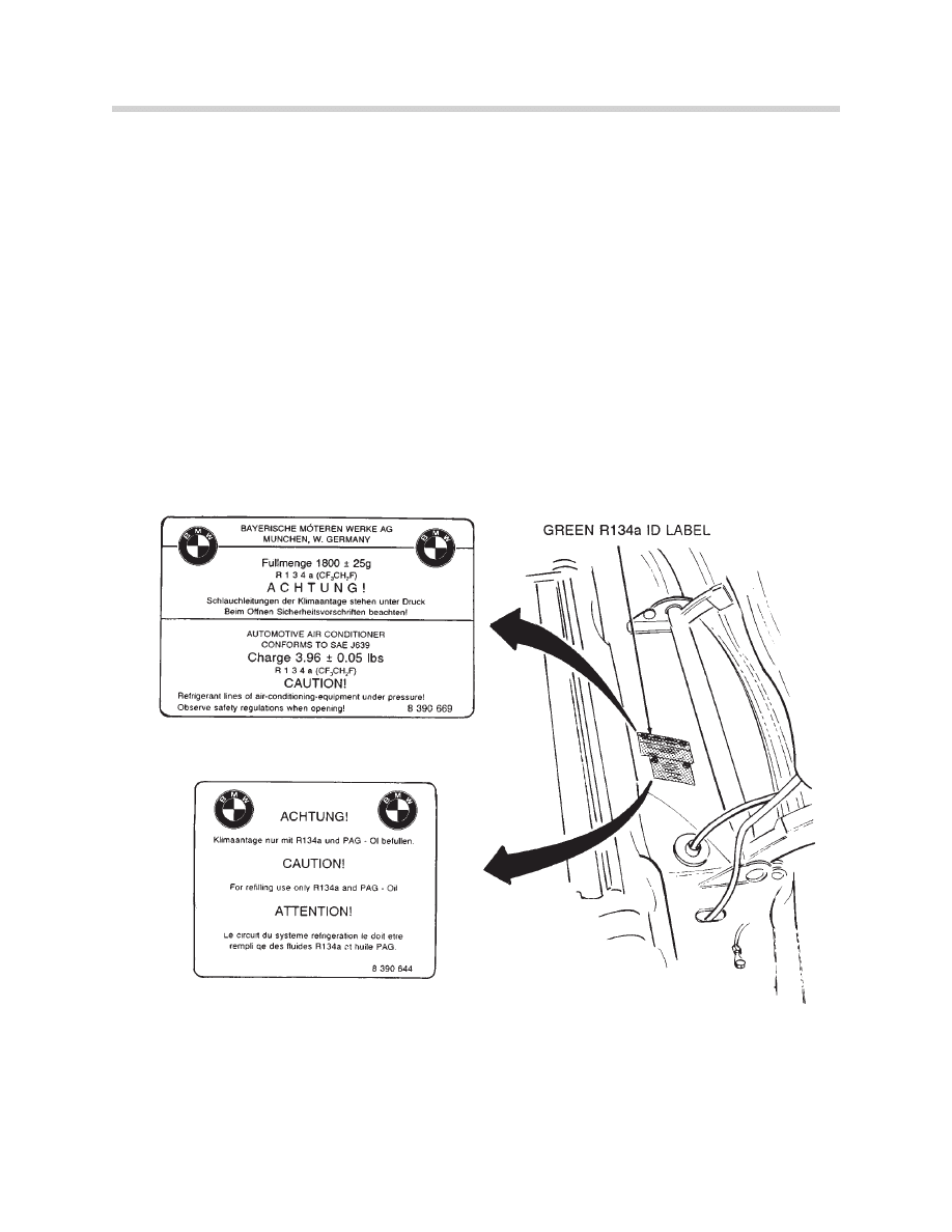
Underhood labels:
— R-12: black.
— R-134a: green.
53
Green R-134a Underhood Label
NOTE:
Charging amount should be according to the underhood label. However, refer
to the S.I.B. # 64 2192 (3695) for refrigerant charge variations
54
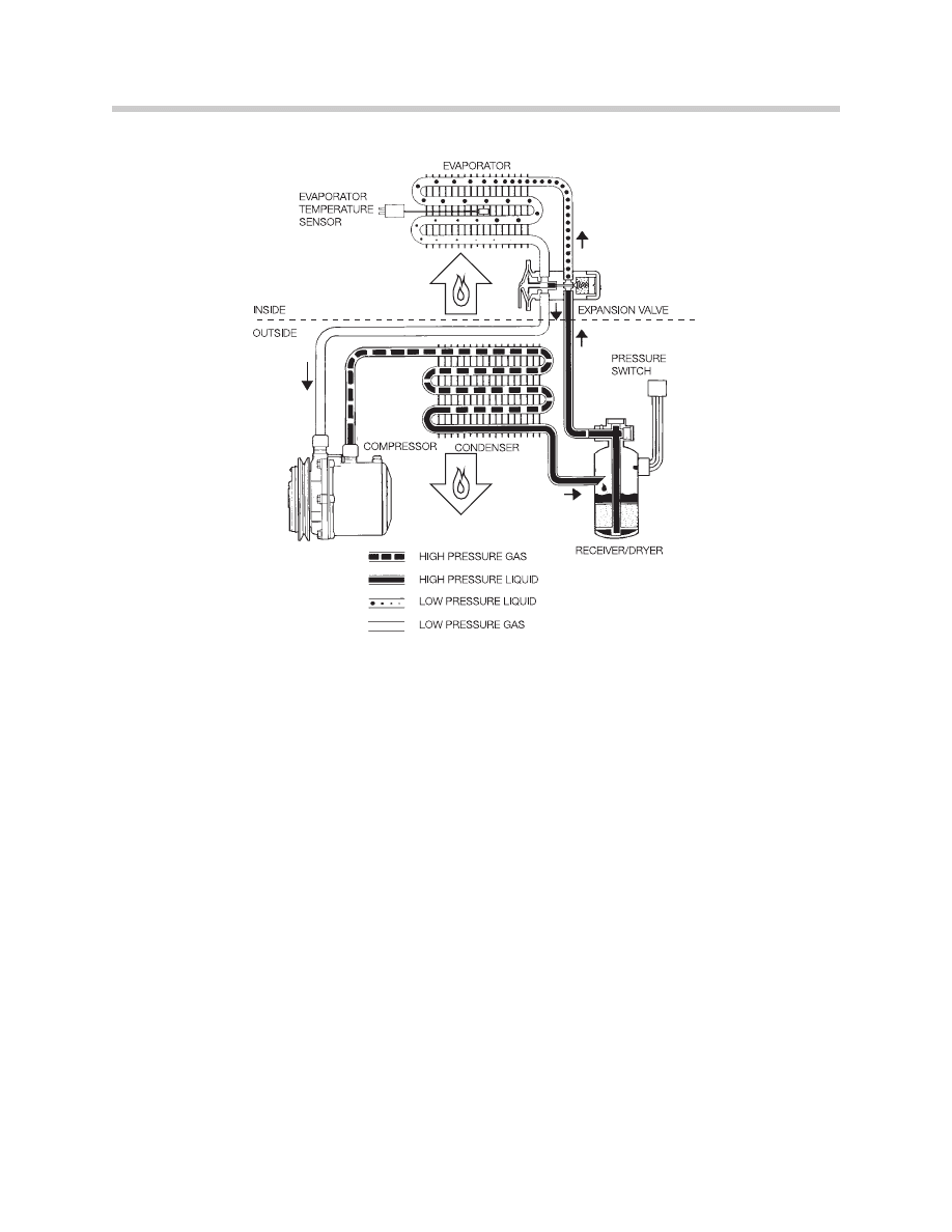
Description
Compressor Clutch
Compressor
Condensor
Receiver/Dryer
Hi/Lo Pressure Switch
Expansion Valve
Evaporator
Temperature Sensor
High Pressure gas, liquid
Low Pressure liquid, gas
Changes
Higher torque capacity
New valving, no melt bolts, PRV, PAG oil RBR seals
High efficiency, no copper parts
Zeolite desiccant, no melt bolts, PRV
New seal materials (RBR)
Special materials for R-134a, RBR seals
Denser fins, high efficiency, no copper
No changes
Higher pressures at high temperature
Higher heat to vaporize
REFRIGERANT HANDLING CERTIFICATION REQUIREMENTS
EQUIPMENT REQUIREMENT
Since Jan. 1, 1993, any technician servicing, repairing, or opening a motor vehicle air con-
ditioning system “for consideration” - anything other than free service- must use either
refrigerant recovery/recycling or recovery-only equipment approved by the EPA.
There are certification requirement for the technicians and the equipment; there are also
record-keeping requirements.
TECHNICIAN TRAINING/CERTIFICATION
Technicians using approved equipment must be trained and certified by an EPA-approved
organization, such as your BMW training center. To be certified, technicians must pass a
test demonstrating their knowledge in the use of recycling equipment in compliance with
SAE Standard J1989, the regulatory requirements, the importance of referant containment,
and the effects of ozone depletion.
EQUIPMENT CERTIFICATION
The equipment owner or another
responsible officer must certify
(report) to the EPA that they own
approved equipment. The informa-
tion provided must include the
name, address, and telephone
number of the establishment where
the recovery/recycling equipment is
located; the name brand, model
number, year and serial number(s)
of the equipment acquired for use
at the establishment; and the signa-
ture of the person who acquired the
equipment (the owner or another
responsible officer), certifying that
they have acquired the equipment ,
that each individual authorized to
use the equipment is properly
trained, and that the information
provided is true and correct.
55
RECORD-KEEPING REQUIREMENTS
If the refrigerant is recovered and sent to a reclamation facility, the name and address of
that facility must be retained.
IMPORTANT DATES
Jan. 1, 1992: Since this date, containment and recycling of R-12 have been required.
Nov. 14,1994: Since this date, the sale of refrigerant in any size container is restricted to
certified technicians.
July, 1995: Since this date, any R-12 mobile air conditioning system that is converted to
use an acceptable alternate refrigerant must have the appropriate unique service fittings
and label for that refrigerant.
Nov. 15, 1995: Since this date, recovery and recycling of any substitute substance for R-
12, such as R-134a, used in a motor vehicle air conditioner have been required.
56
RECOMMENDED REFRIGERANT RECOVERY, RECYCLING, EVACUATION, AND
CHARGING EQUIPMENT
A proper system charging station includes the following components:
•
A manifold gauge set.
•
A charging cylinder.
•
A bulk refrigerant supply tank.
•
A vacuum pump.
•
Hoses for connection to the automotive
A/C system.
•
An electronic leak detector.
•
A thermometer.
This setup will allow you to evacuate and charge
an A/C system.
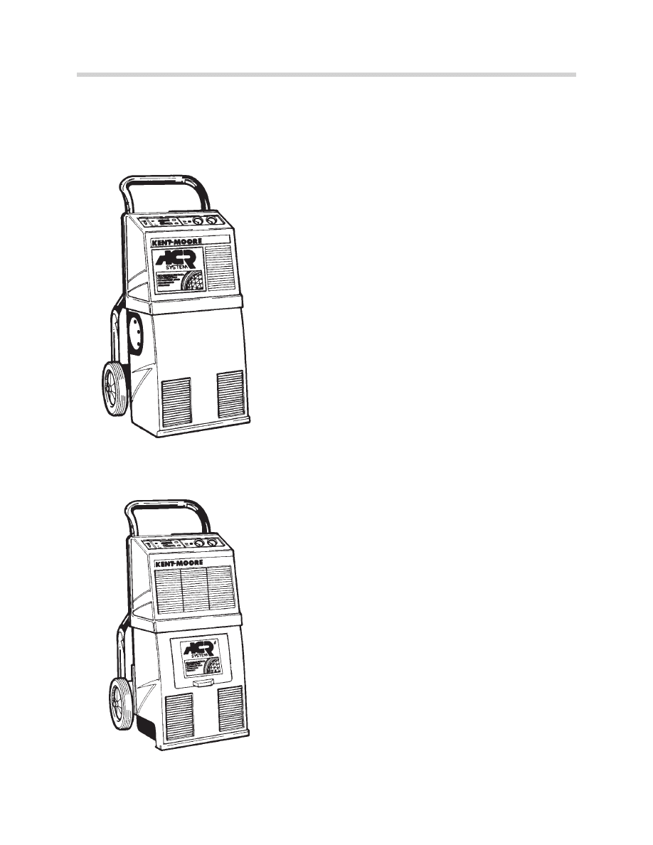
For handling R-12 refrigerant, use an R-12 recy-
cling unit (such as the Kent-Moore ACR
3
).
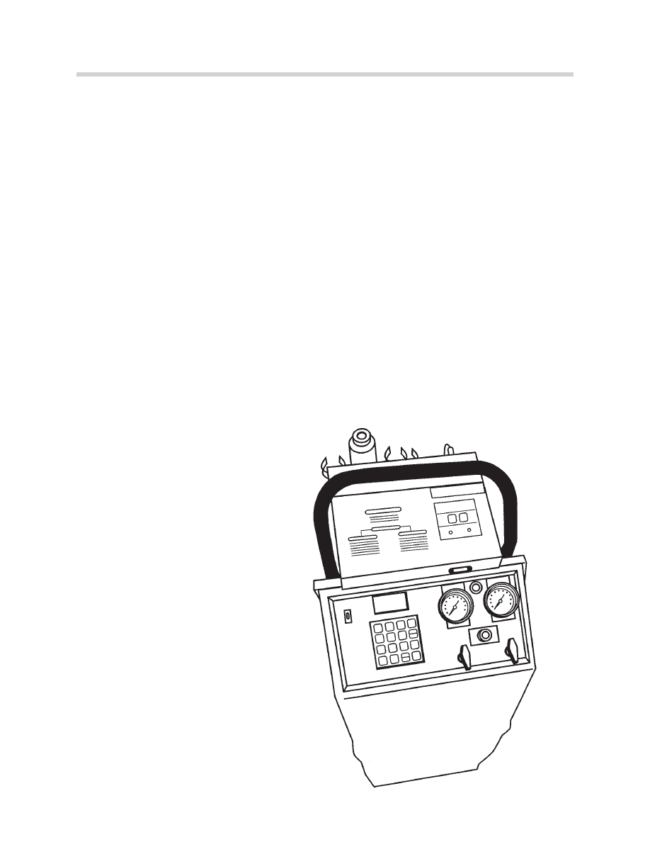
For R-134a refrigerant, a different unit is used (the
Kent-Moore ACR
4
). These units filter and remove
moisture the refrigerant, before discharging it into
a recovery tank.
57
Kent-Moore ACR3
Recovery/Recycling Station
ACR
4
Recovery/
Recycling Station
58
Never use any R-12 service tool, such as manifold gauge sets, on R-134a systems. Tools
retain small amounts of refrigerant and lubricant. Attempting to use the same equipment
on both R-12 and R-134a vehicles will contaminate the air conditioning systems. Manifold
gauge sets must be constructed of the proper hose material and fitting to be compatible
with R-134a. Compatible units should be labeled be appropriately.
When servicing is completed, the protective sealing caps must always be reinstalled to
prevent contamination via the service fittings.
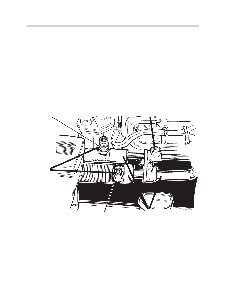
The R134a system (early models) uses a standard sight glass to view the refrigerant
charge. The sight glass view may turn “cloudy” if the wrong compressor oil is used.
HIGH PRESSURE FITTING
LOW PRESSURE FITTING
SEALING
CAPS
SIGHT GLASS
(EARLY MODELS)
GREEN R134a
ID LABELS
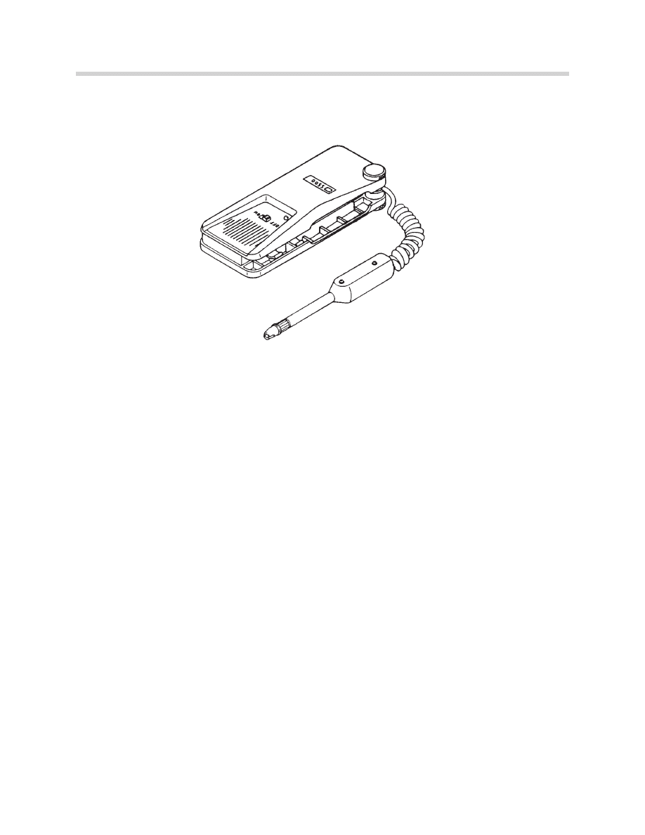
LEAK DETECTORS
R-12 and R-134a systems use different leak detectors. An R-12 leak detector will not
detect R-134a leaks (R-134a molecules are much smaller than R-12 molecules). However,
an R-134a leak detector will detect R-12 leaks (be sure to follow the manufacturer’s
instructions carefully to avoid contamination).
An R-12 leak detector uses a very sensitive pickup which indicates the presence of Freon
when placed below the leak: a white light illuminates or a warning buzzer sounds. It is
easier to find a leak with the engine off, provided the pressure in the A/C system is 70-80
psi overall (slightly overcharged).
Always check for leaks with the engine off. The radiator fan of a running engine will circu-
late the refrigerant around making the leak point difficult to locate.
To check the evaporator, put the leak detector in the drain of the housing or in the center
dash vent.
An R-134a leak detector has been tested and approved by BMW, TIF 5550. It automati-
cally calibrates after it is turned on, and it detects leaks as small as 0.40 oz. of R-12 or R-
134a per year.
BMW does not recommend the use of dyed refrigerant for finding a leak. The dyes can
sometimes impair system operation and and may damage the interior fabrics of the car.
59
Typical Leak Detector
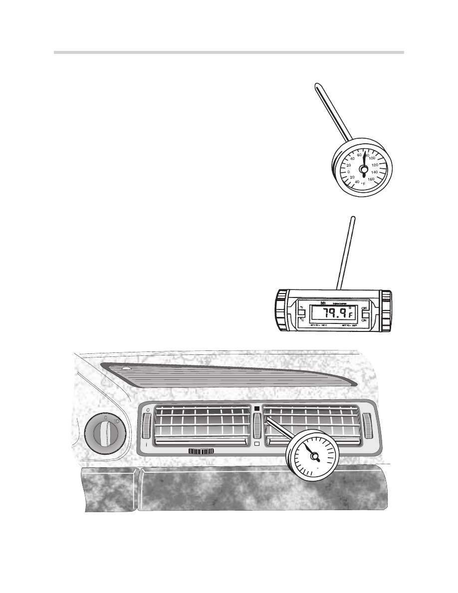
TEMPERATURE SENSING EQUIPMENT
Correct climate control diagnosis requires an accurate and reli-
able temperature sensing device. A high quality analog ther-
mometer or a digital pyrometer is recommended.
TYPICAL USE: A/C PERFORMANCE QUICK CHECK
Test conditions = 90
O
F & 50% Humidity
•
Note ambient temperature
•
Close all windows and doors.
•
Engine Speed = 1500-2000 RPM.
•
Blower Volume = Medium Speed
•
Temperature Wheel = “Max Cold
•
“Snowflake” Button = A/C On
•
Test conditions > 3 minutes
•
Center vent discharge = . 20
O
F less than the ambient temperature.
60
160
F
140
120
100
80
60
40
20
0
20
40
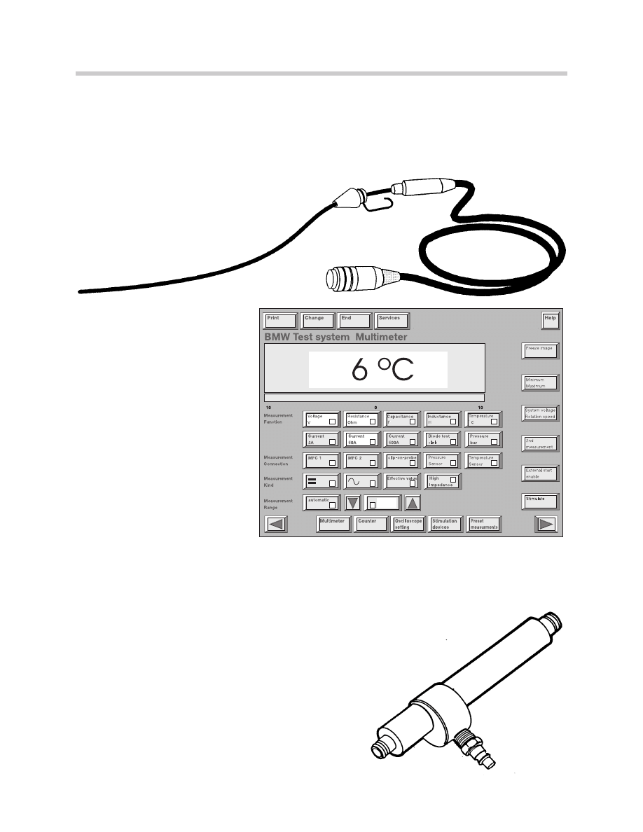
DIS TEMPERATURE PROBE
The Diagnosis and Information System (DIS) tester is equipped with a temperature sensor
cable, stored in the compartment at the rear of the tester. It can be used to measure the
temperatures of liquids and gasses from -20° to 200°C.
To use the DIS as a thermometer:
•
Select “Measurement System”
button on the DIS start
screen.
•
Select “Temperature C”
button on the “Measuring
System Multimeter”
screen.
COOLING / HEAT GUN
To simulate testing temperatures use the approved
“Heating/Cooling Gun Kit,
(Reference SI Bulletin 04 14 89.)
61
SAFETY PRECAUTIONS
The following safety precautions should be observed when working on an automotive
refrigeration system:
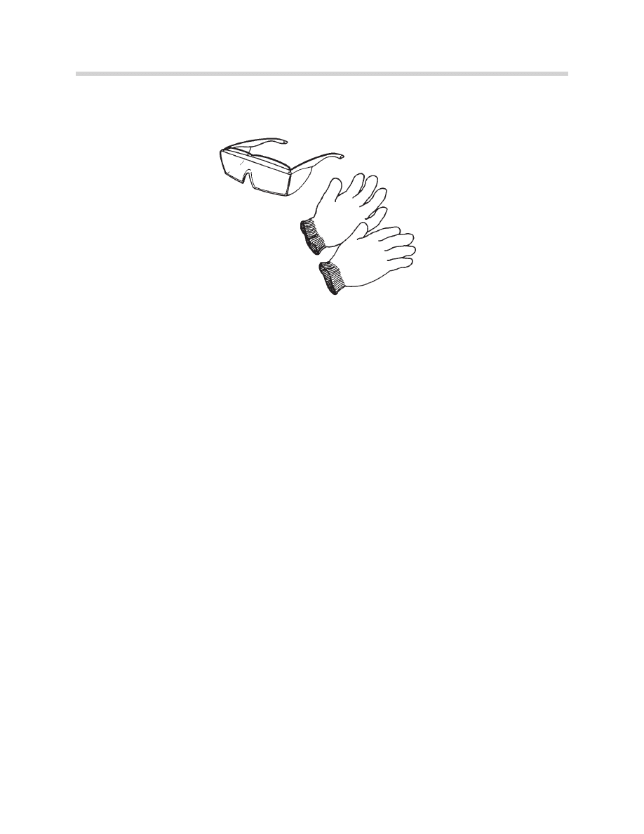
•
Always wear eye protection and gloves while handling refrigerant or servicing an
air conditioning system.
•
Avoid breathing R-134a vapor or mist; exposure may irritate eyes, nose, throat,
and lungs.
•
If refrigerant or compressor oil contacts the skin or eyes, rinse the affected area
with warm water, administer first aid immediately, and consult a doctor.
•
Use only approved service equipment to discharge A/C systems.
•
If an accidental discharge occurs, ventilate the work area.
•
Store refrigerant service equipment and bulk supply containers in a cool, dry
location away from direct sunlight and other heat sources (<113° F, (45° C)).
•
Do not expose refrigerants to an open flame, since burning refrigerant can pro-
duce poisonous gas. This includes open flames (such as in a propane leak
detector), portable heaters, and lit cigarettes.
•
Do not pressure-test service equipment or vehicle A/C systems with an air/R-
134a mixture. Some mixtures of air and R-134a are combustible at elevated
pressures. The use of compressed air for leak detection in an R-134a system
could result in a fire or explosion.
62
Always Use Eye Protection and Gloves

Do not discharge refrigerant into the atmosphere; contain it. R-134a is heavier
than air; if discharged into the atmosphere, it can replace the air, causing suffoca-
tion. If R-12 is discharged into the air it damages the environment.
•
Never weld or steam-clean any part of the air conditioning system. Heating the
refrigerant in a closed system could cause an explosion, due to the increased
pressure.
•
Always consider R-12 or R-134a to be under high pressure, whether in the auto-
mobile refrigeration system, service equipment, or refrigerant storage containers.
•
R-134a should only be handled by competent, informed personnel using
approved procedures and equipment. Failure to do so may result in serious injury
and/or substantial equipment or vehicle damage.
•
Removal of R-134a must be carried out using R-134a equipment that meets the
requirements of SAE J2210.
•
If accidental discharge occurs, ventilate the work area before resuming service.
Exposure to high concentrations of refrigerant vapor can induce anesthetic
effects such as weakness, dizziness, and nausea.
63
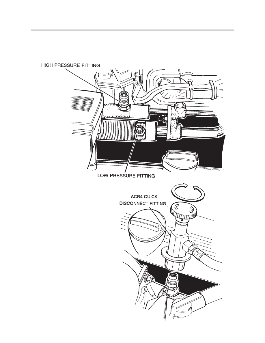
The R134a service fittings are a unique design and prohibit the connection of non-
approved equipment. The large diameter metric fitting is the high side (also sight glass)
while the smaller diameter fitting is the low side.
The ACR4 unit has approved
quick disconnect hose connec-
tors which correspond to the spe-
cial R134a service fittings found
on the vehicle. This arrangement
prevents the accidental connec-
tion of R12 service equipment.
No attempt should ever be
made to bypass these special
fittings
Refer to S.I.B. # 641392 (3646)
for nominal air conditioning
system pressures R12/R134a
64
HIGH PRESSURE
FITTING
65
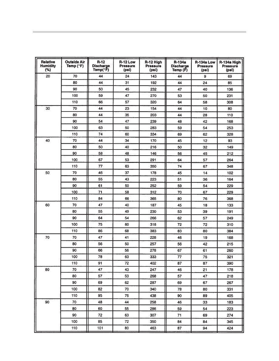
AMBIENT TEMPERATURE / RELATIVE HUMIDITY REFERENCE CHART
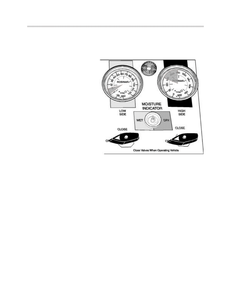
COMPLAINT:
Cooling is not adequate.
CONDITION:
• The low-side gauge reading is
low, or may go into a vacuum.
• The high-side gauge reading
increases as the system oper-
ates.
• The discharge air from the evap-
orator is only slightly cool.
• The expansion valve inlet may
show heaving sweating or frost.
• The high-pressure side is abnor-
mally hot.
DIAGNOSIS:
• The expansion valve is stuck closed; or is plugged by moisture, ice, or foreign material.
CORRECTION:
1. Recover the refrigerant from the system.
2. If the condition described on page 28 exist, replace the receiver/dryer.
3. Evacuate the system for a minimum of 30 minutes* and recharge it.
4. Operate the system and check its performance.
5. If the system fails to function correctly, replace the expansion valve.
*Longer periods of applied vacuum are better.
66

67
COMPLAINT:
Cooling is not adequate.
CONDITION:
• The low-side gauge reading is
too high.
• The high-side gauge reading is
too low.
• The sight glass is free of bub-
bles; the system is fully charged.
(If equipped)
• The discharge air from the evap-
orator is not sufficiently cool.
DIAGNOSIS:
• There may be a leak in the compressor, or the drivebelt may be loose/worn. The com-
pressor pistons, rings, valves, or cylinders may be excessively worn or scored.
CORRECTION:
1. Check the compressor for noisy or knocking operation.
2. Recover the refrigerant from the system..
3. Remove and replace the compressor, if it is noisy/knocking.
4. Examine the condenser for metal fragments - clean if required.
5. Replace the receive/dryer.
6. Evacuate the system for a minimum of 30 minutes* and recharge it.
7. Operate the system and check its performance.
*Longer periods of applied vacuum are better.
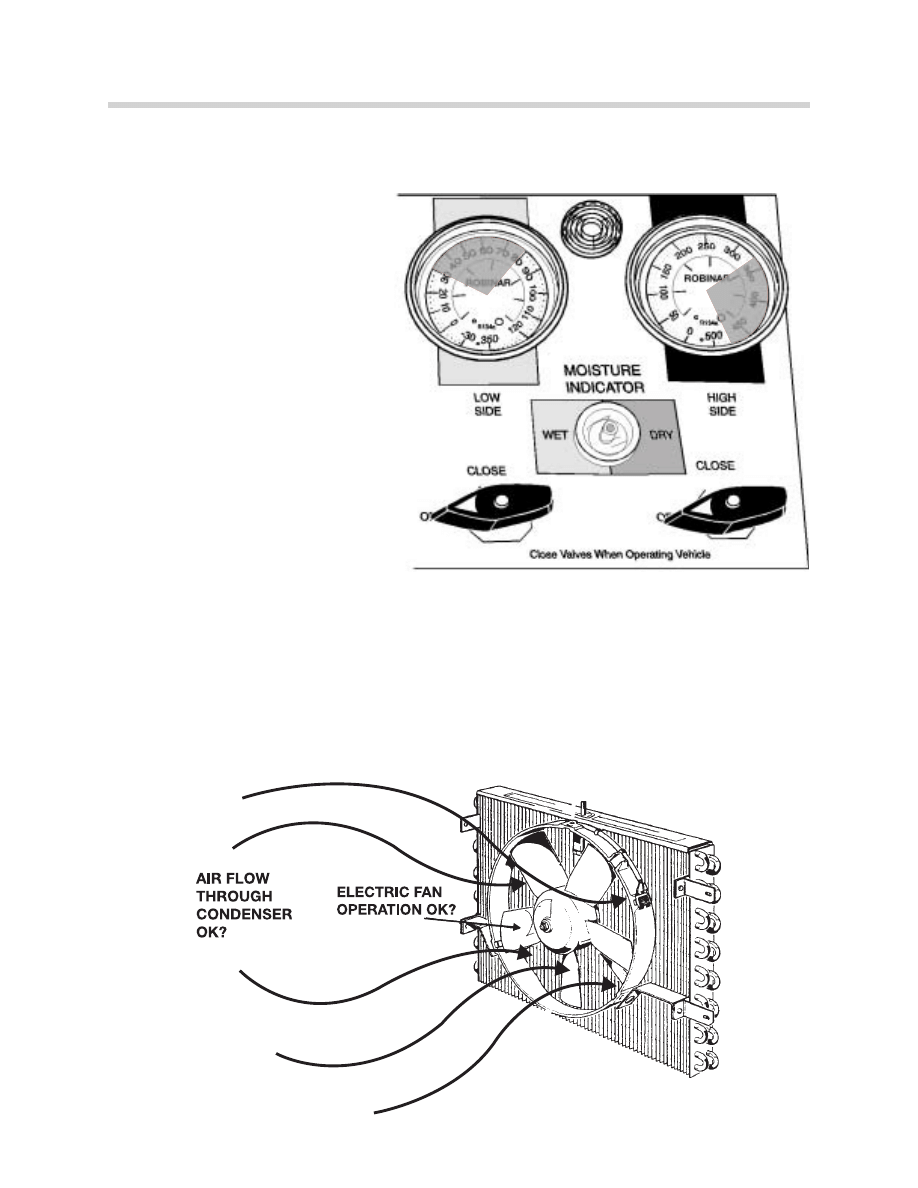
COMPLAINT:
Cooling is not adequate.
CONDITION:
• The low-side gauge reading is
excessively high.
• The high-side gauge reading is
excessively high.
• Bubble may appear occasionally
in the sight glass. (if equipped)
The liquid line is very hot.
• The discharge air from the evap-
orator is warm
DIAGNOSIS:
• The system may be overcharged
• The condenser may not be operating properly.
• Air flow through the condenser may be poor.
• The auxiliary fan may not be operating properly.
68

CORRECTION:
1. Recover the refrigerant.
2. Recharge the refrigerant according to the underhood label or the specifications in TIS.
3. Operate the system and check its performance.
If the gauge readings are still to high:
1. Recover the refrigerant.
2. Blow shop air through the condenser to check whether its passages are free. A con-
denser can be clogged by debris, such as fragments from a failed compressor valve or
desiccant from the receiver/dryer. If the condenser passages are clogged, replace it.
Determine what material clogged the condenser.
3. Replace the receiver/dryer.
4. Evacuate the system for a minimum of 30 minutes* and recharge it.
5. Operate the system and check its performance.
*Longer periods of applied vacuum are better.
69

NON-APPROVED AIR CONDITIONING REFRIGERANTS
Recently, “alternative” refrigerants for automatic air conditioning have been marketed in
certain areas. These refrigerants are claimed to be compatible replacements for the BMW-
approved R-12 refrigerant (also known as Freon ). The “alternative” refrigerants usually
consist of a mixture of various components; among then may be R-12, R-22, R-142b, R-
176, isobutance, propane or ammonia.
These refrigerant components are not related to, and not as ecologically sound as, the
new R-134a refrigerant.
THIS TYPE OF “ALTERNATIVE” REFRIGERANTS IS NOT COMPATIBLE WITH, AND
NOT APPROVED FOR USE IN BMW AIR CONDITIONING SYSTEMS.
Problems than can occur when charging a BMW air conditioning system with an alterna-
tive mix or “blend”:
1. R-22 is incompatible with the existing R-12 desiccant found in BMW receiver-dryers.
The desiccant will break down, and may be distributed through the A/C system, clog-
ging the expansion valve and destroying the compressor. Some products use
“sealants” which can clog orifices in both the vehicle and recycling equipment.
2. R-22 can result in substantially higher pressure when installed in a system designed for
R-12, especially in stop-and-go traffic in high ambient temperatures.
3. Current R-12 hoses, O-rings and sealing materials found on BMW vehicles are not
designed to, and do not, retain R-22. The R-22 permeates out of the hoses. If the R-
12 is then lost from the system, the remaining R-142b is flammable.
4. If a vehicle with a non-approved refrigerant is brought into a shop and connected to
recycling equipment, the same problems can occur with the recycling equipment. In
addition, the “alternative” refrigerant can be passed on to other vehicles that are con-
nected to the same recycling equipment. This could spread the problems to other
vehicles.
5. Materials such as propane and isobutane are flammable. If the proper pressure and
charge conditions are not maintained, these components “fractionate” out of the mix-
ture. While the blended components may not be flammable, the individual components
may be flammable if the mixture has fractionated.
70

6. Automotive A/C systems are subject to Federal law, as well as specific state require-
ments. Currently, 10 states and the District of Columbia have enacted requirements
that generally follow SAE definitions and requirements. The SAE J639 standard
requires that “...Blend refrigerants, both in the original composition and in the composi-
tions created as a result of normal mobile air-conditioning operating conditions, must
meet the previous [ASHRAE 34-78] criteria: low toxicity, nonflammable, and nonexplo-
sive requirements.”
7. Blend refrigerants often require costly special processing to recycle. Since they cannot
be vented to the atmosphere, servicing the system requires removal of the material into
dedicated containers and shipping the material to a processing center for reclamation
or destruction. The shipping must be done according to state and federal regulations,
and the material is classified as a flammable gas for shipping purposes.
Solution:
There are currently no BMW-approved alternative refrigerants to R-12 or R-134a.
Use of any refrigerant other than R-12 or R-134a will preclude warranty coverage of result-
ing failures.
Protect your customer’s air conditioning systems as well as your own recycling equipment.
Do not allow non-approved refrigerants to enter your recycling equipment.
If a customer has had air conditioning service performed elsewhere, determine that only
approved refrigerant was used for recharging the system. This Service Information can be
used to explain potential problems to customers.
SYSTEM CONVERSION
WHEN TO RETROFIT
As long as R-12 is available, it should be used to service a vehicle with an R-12 system.
When R-12 supplies are unavailable, the customers may be willing to pay for a retrofit.
STANDARD RETROFIT
To achieve the most effective system retrofit, follow the instructions in Service Information
Bulletin # 64 01 95 (4179). Retrofit kits have been developed for the E31, E32, E34, and
E36 models, to provide comparable system performance. The kits include a new receiv-
er/dryer, hoses, service fitting, refrigerant controls, and other parts.
71

VERIFIED SYSTEM MALFUNCTION FOLLOW-UP
After verifying that the complaint is actually a system malfunction, make the following
“basic” checks:
VISUAL CHECKS
• Coolant level, coolant hoses in perfect condition and all drive belts tensioned properly.
• A/C condenser, radiator, and system microfilters clean and unobstructed.
• Auxiliary cooling fan operates with A/C on and rotates in the correct direction.
• Interior flow-through ventilation functions correctly, vent flap valves behind rear bumper
open with interior overpressure.
DIS TESTER CHECKS
• Instrument cluster temperature gauge and Engine Control Module temperature value
indicate engine coolant temperature is normal.
• IHKR/IHKA has no faults in memory and the system is not operating with stored substi-
tute values.
• Water valves open/close correctly, heater core temperature sensors indicate that the
heater cores cool down on system cue.
• Outlet flaps operate correctly, actual air discharge locations agree with tester indicated
flap open/closed positions.
• A/C compressor clutch energizes on system cue with engine running. (Many systems
will not energize the compressor clutch with the ignition switched on, engine not run-
ning.)
72

BASIC TROUBLESHOOTING
• Always personally verify the customer complaint.
• Always verify that the complaint is truly a system malfunction.
• Perform a Quick Test to determine if the vehicle systems have logged fault codes.
• Call the faulted system or appropriate test schedule to verify the correct control module
is installed in the car.
• Follow the Diagnostic Information System (DIS) on screen instructions and perform all
tests as specified.
• Use the DIS and fault symptom diagnostic procedures as trained.
• Follow the appropriate test module procedures for systems that malfunction but fail to
set faults in memory.
• System problems which elude diagnostic procedures must be brought to the attention
of BMW of North America, Inc.
• BMW Technical Assistance Hotline 1-800-472-7222
73
Document Outline
- Main Menu
- Climate Control P1
- Climate Control P2
- Climate Control P3
- IHKS
- IHKS E52
- Understanding Climate Control Sys.
- Understanding Solar Sensors
- IHKA E38
- IHKA E39
- IHKR E39
- IHKR & IHKA E53
- IHKA E46
- IHKR E46
- IHKA E36
- Inputs
- Outputs
- E85 Heating/Air Conditioning Sys.
- E65 IHKA
- Rear Air Conditioning
- Updates
Wyszukiwarka
Podobne podstrony:
Climate Control
Climate Control
08 E70 Climate Control WB
09 Climate Control Glossary
03 Exploded View & Part List
Climate Control
08 03 12 Controlling strategiczny wykład
08 E60 Climate Control
09 E90 Climate Control
Encyclopedia Biblica Vol 2 Gospels part 03
part 03 bis
Controlling ćw 14 11 03
part 03
Cw inz Pn 2015 part 03 cw 4 id Nieznany
rachunkowo 9c e6+w+systemie+controllingu+ +wyk b3ad+2+ 2820 03 2006 29 O36C33UTDWYK6E2RPILR4TADDZGAW
R J2 Controller Profibus DP Operator Manual [B 80844EN 03]
part 03 bis
więcej podobnych podstron