
WIRELESS MOTION
DETECTOR
MANUAL
KTPIRS3
GLOLAB
CORPORATION

2
Thank you for buying our model KTPIRS3 Wireless Motion Detector kit.
The goal of Glolab is to produce top quality electronic kits, products and components. All
of our kits are designed by Glolab engineers and tested in our laboratory. Mechanical
devices, prototypes and enclosures are fabricated in our precision machine shop.
Glolab Corporation has two locations in New York’s Hudson Valley. Our electronics
laboratory and kit packaging is located in Wappingers Falls and our machine shop is in
Lagrangeville.
We think that Glolab kits are the easiest to assemble of any available. To ease assembly
for both experienced and new kit builders, we package each part in individual plastic zip-
lock envelopes that are labeled with the value and part number. It is not necessary to
read resistor color codes or capacitor number codes while assembling the PC boards.
You simply locate the part and insert it into the PC board where the corresponding part
number is marked on the board. Each kit includes assembly instructions and a complete
description of how it works.
In addition to our kits, we supply some special and hard to find parts for those of you
who want to design and build your own projects.
Technical help is available by email from lab@glolab.com.
NOTICE: THIS DEVICE IS NOT CERTIFIED BY THE FEDERAL COMMUNICATIONS
COMMISSION. IF IT IS USED IN A PRODUCT, THAT PRODUCT MUST BE SENT TO
A TESTING LABORATORY AND SUBMITTED FOR FCC CERTIFICATION BEFORE IT
CAN BE SOLD
Copyright
1999
Glolab Corporation
307 Pine Ridge Drive
Wappingers Falls, NY 12590

3
Introduction______________
Motion detectors are used mostly to turn lights on when they sense movement of people
or vehicles. The detector device is often built into an outdoor flood or porch light to
illuminate a driveway or porch at night making it easier to enter your house without
having to leave the light on while you are away. They also add security by turning the
outside light on at night when motion is detected even while you are at home.
Detectors are available that are intended for use with security systems to sound an
alarm or summon police when motion is detected even during daytime but these are
usually expensive and must be wired to the alarm control box. If security is your main
concern, this may be a good choice.
However, it is often convenient just to know when a person is approaching your front or
back door or when a vehicle enters your driveway even in daytime. If several detectors
are used, you can also identify where the motion is taking place.
The Wireless Motion Detector system described here is designed to detect motion over a
narrow field of less than ten degrees so that the area where motion occurs is easily
identified. The motion detector includes a pyroelectric sensor, amplifier, encoder,
transmitter and a battery operated power supply housed in a plastic enclosure. The
enclosure can be attached to a wall or other surface using a Velcro fastener. It can be
located indoors and also outdoors if it is protected from the weather with some type of
housing.
How it works______________
Detector
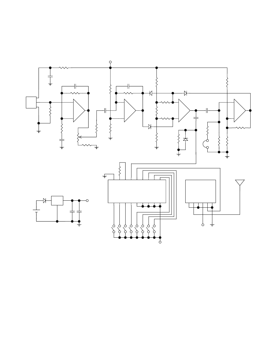
Figure 1 is a schematic of the detector. PIR is a PIR325 dual element pyroelectric
infrared sensor having a built-in FET amplifier. It also has an optical filter that passes
infrared in the 5 to 14
µm range that is most sensitive to human body radiation. As an
object that emits infrared passes in front of the PIR, its output goes either more positive
or more negative depending on the direction of travel. Since the output signal is very
small, it is passed through two stages of amplification having a total maximum gain of
about 10,000. Range is controlled by potentiometer R5 which adjusts the gain from 1000
to 10,000.
R1 and C1 filter any noise from the power that feeds the PIR and R2 is a load for the
FET within the PIR. IC1 is either a Maxim MAX407 or Linear Technologies LT1495 dual
micropower operational amplifier. R3, R4 and C2 set the IC1A amplifier gain and
reference voltage and C3 limits its bandwidth to about 10Hz. C4 couples the output of
IC1A into IC1B. R5, R6, R7 and R10 set the gain of IC1B and C5 limits its bandwidth to
about 10Hz. R7 and R9 set its bias to 2.5 volts.

4
IC2 is either a Maxim MAX922 or a Linear Technologies LTC1440 dual micropower
comparator. IC2A functions as a window comparator and also functions together with
IC2B as a single shot. When no motion occurs and there is no output from the PIR, the
output of IC1B at pin 7 rests at 2.5 volts. Resistive divider R11, R12 and R13 apply a
bias input through R14 and R15 to pin 5 and pin 6 of IC2A. The level at pin 5 is 250MV
more positive than at pin 6, forcing output pin 8 to a down level.
When motion is detected that produces a positive transition at IC1B pin 1, then pin 6 of
IC2A is forced up through D2 and becomes more positive than pin 5. This causes output
pin 8 to go up. If the motion produces a negative transition at IC1B pin 1 then IC2A pin 5
is forced down through D1 which also causes IC2A output pin 8 to go up.
The positive transition at IC2A pin 8 couples through C6 into IC2B, turning it on and
causing its output pin 1 to go down. This down level pulls IC2A pin 5 down through D3
and latches it down until C6 discharges through R17 and, or R18. When C6 discharges
below the reference voltage at pin 3, IC2B turns off and pin 1 goes up again. The circuit
is now ready to respond to motion again. Program jumper PJ places a lower value R17
in parallel with R18 to reduce the time constant during testing, The C6, R15, R18 time
constant is about 90 seconds without PJ and 1 second with PJ. The 90 second delay
avoids rapidly repeating messages when someone remains in view of a detector, for
example, when someone is standing near your front door awaiting entry. R19, R20 and
R21 produce hysteresis to avoid jitter in the IC2B output during the slow discharge of C6
and they also set its reference. C7 R16 and D4 couple a narrow negative pulse into
Holtek HT680 encoder IC3 to initiate a transmit sequence.
Upon being triggered by IC2B, the encoder generates three groups of bits containing
data and address information and serially sends them to transmit module TM1V. The
encoder addresses can be programmed by 8 position DIP switch SA positions 1, 2 ,3
and 4. These switches may be set all OFF or in any ON - OFF combination for up to 16
binary addresses so that if more than one set of detectors and receivers are used you
can control which detector sends to which receiver. Each detector can also be
programmed to be received by one of four data channels in a four channel receiver. Its
data inputs are programmed by SA positions 5, 6, 7 and 8 to identify the detector as
number 1, 2, 3 or 4. Only one of these switches should be ON.
The circuits are powered with 5 volts through reverse polarity protection diode D5 and
Seiko 81250SGY low dropout micropower regulator IC4 by a 9 volt battery. Because of
the micropower circuits used in this detector, standby current is only 20 microamperes
which is about 100 times less than that of other motion detectors. A 9 volt alkaline
battery will power this device for more than 2 years and a 9 volt lithium battery is
estimated to power it for 8 years. When the battery voltage drops below 5 volts a low
battery condition will be indicated by continuously repeating transmissions with no
movement in front of the sensor.

5
Construction______________
PC Board
Attach the Fresnel lens inside the enclosure with its grooves facing in. Hold it in place
with pieces of scotch tape along the edges. Position the lens carefully by holding it up to
a light source so it is well centered over the enclosure hole. Place an O ring under the
PIR to space it off the board and solder the PIR in place. This spacing ensures proper
focal distance between the Fresnel lens in the enclosure cover and the PIR. Sockets are
used for all of the DIP ICs. To assemble the board mount all of the small components
first, then add the sockets. After all components are mounted feed the leads from a 9
volt battery connector through a hole in the battery compartment of the enclosure and
solder them to the transmitter board holes marked plus V and minus V. Feed the
antenna through a hole in the enclosure and attach it to the terminal block.
Testing
A KRETS3 event receiver having four data channels may be used to test the operation
of one or more detectors. Connect a piezo buzzer to the receiver momentary terminal
and to ground. Connect an LED in series with a 470 ohm resistor to receiver output
terminal block position 1 and to the +12 volt terminal. Be sure to connect the long LED
lead to +. Connect a normally open push button reset switch to RES and +5. Plug the
receiver wall transformer into a receptacle. Set SB in the receiver for all positions OFF.
After a signal is received the output latch can be reset with the push button switch.
Connect a 9 volt battery to the detector. Set address switch SA positions 1, 2, 3 and 4
OFF. Set data position 5 on to identify it as detector 1. Put program jumper PJ in place.
You are now ready to detect motion and transmit data to a receiver. Repeat for any
additional detectors using SA positions 6, 7 or 8 to identify each one. For additional
detectors you will also need corresponding LEDs in the receiver.
Operation
Since the detector is battery operated and portable, it is ideal for temporary applications
such as to warn that your cat is on the kitchen table eating the turkey that was just
cooked or to signal the movement of a child without having to view a video monitor.
Infrared in the range of 8 to 14 microns cannot pass through ordinary window glass,
plastic and most materials that can pass visible light. It can however, pass through with
some loss in sensitivity, germanium and silicon which are completely opaque to visible
light. An unprocessed reject silicon wafer makes a good infrared window for a weather
resistant outdoor housing. The pyroelectric sensor is sensitive to movement across its
surface in a horizontal direction only, when the antenna is vertical facing either up or
down.
6
WIRELESS MOTION DETECTOR
FIGURE 1
ANTENNA
+5
SA
1
2
3
4
5
6
7
8
9
10 11 12 13 14 15 16 17 18
1
R1 10K
R2
100K
R4 10M
C6 10
D1
R14 10M
D3
R16
R12
10M
2
3
1
5
6
PIN 7 = +5
PIN 2 = GND
IC1A
IC1B
IC2A
IC2B
+5
IC2 = MAX922
+
+
+
+
_
_
_
_
200K
+5
C8
C9
.1
100
6 - 9 VOLTS
1
+
D5
+
R10 10M
5
6
7
C1
10
+
C3
.01
C5
.01
C4 1
+
R7
100K
D2
R8
10M
10M
R9
R11
2M
2M
R13
10M
R15
R21 10M
10M
R19
D4
R3
100K
C2
1
+
1
4
3
8
+
+5
2
3
4
5
6
7
8
R18
10M
2
1
3
R5
1M
PIN 1 = +5
PIN 4 = GND
IC1 = MAX407
R6 100K
R17
100K
R20
3M
C7
.01
2 3 4 5 6
PJ
R22
120K
IC3
HT-680
TM1V
TRANSMIT
MODULE
PIR
IC4

7
This page intentionally left blank
8
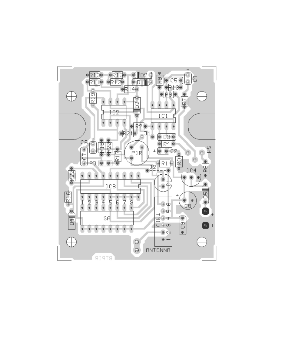
PC Board Layout
FIGURE 2
This single sided PC board requires two jumpers to complete the circuits. Install these
jumpers as indicated in the layout above and on the board screening before any
components are installed. Excess leads from resistors may be used as jumpers.

9
Parts List
Wireless Motion Detector Transmitter parts
Source
P/N
R1 - 10K 1/8 watt 5%
Mouser
299-10K
R2, R3, R6, R7, R17 - 100K 1/8 watt 5%
Mouser
299-100K
R4, R8, R9, R10, R14 R15 - 10 MEG 1/8 watt 5%
Mouser
299-10M
R16, R18, R19, R21 - 10 MEG 1/8 watt 5%
Mouser
299-10M
R20 - 3 MEG 1/8 watt 5%
Mouser
299-3M
R5 - 1 MEG potentiometer
Digi-Key
36G16
R11, R13 - 2 MEG 1/8 watt 5%
Mouser
299-2M
R12 - 200K 1/8 watt 5%
Mouser
299-200K
R22 - 390K 1/8 watt 5%
Mouser
299-390K
C1 - 10 MFD 16 volt low leakage electrolytic
Mouser
140-LLRL16V10
C2, C4 - 1 MFD 16 volt tantalum
Digi-Key
P2105
C3, C5, C7 - .01 MFD 50 metalized film
Digi-Key
P4513
C6 - 10 MFD 6.3 volt tantalum
Digi-Key
P2013
C8 -100 MFD 10 volt low leakage electrolytic Mouser 140-LLRL10V100
C9 - .1 MFD 50 volt metalized film
Digi-Key
P4525
D1, D2, D3, D4, D5 - 1N914B diode
Mouser
583-1N914B
SA - 8 position DIP switch
Digi-Key
CKN1282
IC sockets - two 8 pin
Mouser
571-3902612
IC socket 18 pin
Mouser
571-3902615
O-ring spacer
MSC
09260092
PIR – PIR325 pyroelectric infrared sensor
Glolab
PIR325
IC1 – Maxim MAX407CPA micropower op amp
Maxim
MAX407CPA
IC2 – Maxim MAX922CPA micropower comparator
Maxim
MAX922CPA
IC3 - Holtek HT-680 encoder
Glolab
HT-680
IC4 – Seiko 81250SGY 5 volt regulator
Mouser
628-81250SGY
9 volt battery connector
Mouser
123-6004
1 position antenna terminal block
Glolab
ATB1
6.7 inch antenna wire
Glolab
WC418
Transmit module
Glolab
TM1V
Transmit circuit board to fit S211FL enclosure
Glolab
BTPIR
Infrared Fresnel lens
Glolab
FL65
Enclosure with hole for Fresnel lens
Glolab
S211FL
Digi-Key 1-800-344-3539
www.digikey.com
Mouser 1-800-346-6873
www.mouser.com
MSC Industrial Supply Co. 1.800-645-7270
www.mscdirect.com
Maxim Semiconductor
www.maxim-ic.com
Buy
online

10
KTPIRS3 Assembly Instructions
Before soldering components, check to be sure that they are in the correct place and
that polarity sensitive components are inserted in the correct direction. Bend resistor and
diode leads close to the component body. Insert resistors, capacitors and diode and
bend their leads against the board. Cut the leads off short enough so they do not short
to adjacent lands but leave them long enough to retain the component on the board.
1. Insert all small components such as jumpers diodes and resistors first, being careful
to insert the diodes with their cathode bands in the correct direction as shown on the
PC board.
2. Insert all small capacitors.
3. Insert all IC sockets with their notch in the direction indicated on the PC board.
4. Insert DIP switch and potentiometer R5.
5. Solder all inserted components. Hold the sockets and switches against the board
while soldering a few pins, then solder all remaining pins.
6. Place O ring spacer over PIR leads and insert and solder PIR in board.
7. Insert voltage regulator IC4, solder it and then cut off excess leads. IC4 should stand
at least 1/8” off the board.
8. Insert antenna terminal and solder.
9. Insert module TM1V with its module side facing the edge of the board and solder.
Excess leads may be cut off.
10. Insert each IC in its socket with its pin 1 indicator toward the socket notch. Handle
ICs as static sensitive devices.
11.
Insert the battery connector leads through a hole in the enclosure battery
compartment. Insert the red lead in the board hole marked + and the black lead in the
hole marked - and solder.
12. Mount the PC board in the enclosure with four #4 X 3/8” screws
13. Insert the antenna through a hole in the enclosure and into the antenna terminal.
14. attach the top enclosure with two screws provided
15. Place a 9 volt alkaline battery into the battery compartment and close the cover

11

12
GLOLAB
CORPORATION
307 Pine Ridge Drive
Wappingers Falls, NY 12590
voice - (845) 297-9771
Fax - (845) 297-9772
Email - lab@glolab.com
http://www.glolab.com
1999 Glolab Corp.
Wyszukiwarka
Podobne podstrony:
(EE project) BROAD BAND 2MHz OPTICAL FIBER RECEIVER U6NERKQGZGGI5GTI2JHKHPASTV5SNBXM7QR6ECA
(EE project) BROAD BAND 50MHz OPTICAL FIBER RECEIVER VERSION A VOJGZ2JKTPIG7U65EU4PVIEF5STBD4XSJ7MUY
(EE project) BROAD BAND 5MHz OPTICAL FIBER RECEIVER 3KGBQ5QXD34N3KOK4GW4KJVZWBUET47KKQVPX6A
(EE project) 63 67
(EE project) EMP Aggregatet
(EE project) Hardwire buggsändare(1)
(EE project) FM sändare 88 108MHz(1)
(EE project) FM Mottagare TDA7000(1)
(EE project)
(EE project) Glimmtändare
(EE project) digit 5x7(1)
(EE project) FM sändare FM 79 (r=2500m)(1)
Projectile Motion 1
Prezentacja ZPR MS Project
Detector De Metales
OAEB Staining to Detect Apoptosis
więcej podobnych podstron