Processes
Description
Resistance Spot Welder
Resistance Spot
Welding
003 335D
2012−06
Visit our website at
www.MillerWelds.com
HANDBOOK FOR
Resistance
Spot
Welding

TABLE OF CONTENTS
SECTION 1 − SAFETY PRECAUTIONS - READ BEFORE USING
. . . . . . . . . . . . . . . . . . . . . . . . . . . . . . . . .
1-2. Resistance Spot Welding Hazards
1-3. Additional Symbols For Installation, Operation, And Maintenance
. . . . . . . . . . . . . . . . . . . . . . . . . . . . .
1-4. California Proposition 65 Warnings
1-5. Principal Safety Standards
SECTION 3 − FUNDAMENTALS OF RESISTANCE SPOT WELDING
. . . . . . . . . . . . . . . . . . . . . . . . . . . . . .
3-6. Practical Uses Of Resistance
3-8. Pressure Or Welding Force
3-11. Materials Data For Resistance
3-15. Steels, Dip Coated Or Plated
3-16. Aluminum And Aluminum Alloys
SECTION 4 − MAINTENANCE AND TROUBLESHOOTING
. . . . . . . . . . . . . . . . . . . . . . . . . . . . . . . . . . . . . . .
003 335 Page 1
SECTION 1 − SAFETY PRECAUTIONS - READ BEFORE USING
spotom_2011-10
Protect yourself and others from injury —
read, follow, and save these important safety precautions and operating instructions.
1-1. Symbol Usage
DANGER! − Indicates a hazardous situation which, if
not avoided, will result in death or serious injury. The
possible hazards are shown in the adjoining symbols
or explained in the text.
Indicates a hazardous situation which, if not avoided,
could result in death or serious injury. The possible
hazards are shown in the adjoining symbols or ex-
plained in the text.
NOTICE − Indicates statements not related to personal injury.
Indicates special instructions.
This group of symbols means Warning! Watch Out! ELECTRIC
SHOCK, MOVING PARTS, and HOT PARTS hazards. Consult sym-
bols and related instructions below for necessary actions to avoid the
hazards.
1-2. Resistance Spot Welding Hazards
The symbols shown below are used throughout this manual
to call attention to and identify possible hazards. When you
see the symbol, watch out, and follow the related instructions
to avoid the hazard. The safety information given below is
only a summary of the more complete safety information
found in the Safety Standards listed in Section 1-5. Read and
follow all Safety Standards.
Only qualified persons should install, operate, maintain, and
repair this unit.
During operation, keep everybody, especially children, away.
SPOT WELDING can cause fire or explosion.
Sparks can fly off from the welding arc. The flying
sparks, hot workpiece, and hot equipment can
cause fires and burns. Accidental contact of elec-
trode to metal objects can cause sparks, explosion,
overheating, or fire. Check and be sure the area is safe before doing
any welding.
Remove all flammables within 35 ft (10.7 m) of the weld. If this is not
possible, tightly cover them with approved covers.
Do not spot weld where flying sparks can strike flammable material.
Protect yourself and others from flying sparks and hot metal.
Be alert that welding sparks can easily go through small cracks and
openings to adjacent areas.
Watch for fire, and keep a fire extinguisher nearby.
Do not weld on containers that have held combustibles, or on
closed containers such as tanks, drums, or pipes unless they are
properly prepared according to AWS F4.1 and AWS A6.0 (see
Safety Standards).
Do not weld where the atmosphere may contain flammable dust,
gas, or liquid vapors (such as gasoline).
Remove any combustibles, such as a butane lighter or matches,
from your person before doing any welding.
After completion of work, inspect area to ensure it is free of sparks,
glowing embers, and flames.
Do not exceed the equipment rated capacity.
Use only correct fuses or circuit breakers. Do not oversize or
bypass them.
Follow requirements in OSHA 1910.252 (a) (2) (iv) and NFPA 51B
for hot work and have a fire watcher and extinguisher nearby.
Touching live electrical parts can cause fatal shocks
or severe burns. The input power circuit and
machine internal circuits are also live when power is
on. Incorrectly installed or improperly grounded
equipment is a hazard.
ELECTRIC SHOCK can kill.
Do not touch live electrical parts.
Wear dry, hole-free insulating gloves and body protection.
Additional safety precautions are required when any of the following
electrically hazardous conditions are present: in damp locations or
while wearing wet clothing; on metal structures such as floors, grat-
ings, or scaffolds; when in cramped positions such as sitting,
kneeling, or lying; or when there is a high risk of unavoidable or acci-
dental contact with the workpiece or ground. For these conditions,
see ANSI Z49.1 listed in Safety Standards. And, do not work alone!
Disconnect input power before installing or servicing this equip-
ment. Lockout/tagout input power according to OSHA 29 CFR
1910.147 (see Safety Standards).
Properly install, ground, and operate this equipment according to
this manual and national, state, and local codes.
Always verify the supply ground − check and be sure that input pow-
er cord ground wire is properly connected to ground terminal in
disconnect box or that cord plug is connected to a properly
grounded receptacle outlet.
When making input connections, attach the grounding conductor
first − double-check connections.
Keep cords dry, free of oil and grease, and protected from hot metal
and sparks.
Frequently inspect input power cord and ground conductor for dam-
age or bare wiring − replace immediately if damaged − bare wiring
can kill. Check ground conductor for continuity.
Turn off all equipment when not in use.
For water-cooled equipment, check and repair or replace any leak-
ing hoses or fittings. Do not use any electrical equipment if you are
wet or in a wet area.
Use only well-maintained equipment. Repair or replace damaged
parts at once.
Wear a safety harness if working above floor level.
Keep all panels, covers, and guards securely in place.
003 335 Page 2
Very often sparks fly off from the joint area.
Wear approved face shield or safety goggles
with side shields.
FLYING SPARKS can injure.
Wear protective garments such as oil-free, flame-resistant leather
gloves, heavy shirt, cuffless trousers, high shoes, and a cap.
Synthetic material usually does not provide such protection.
Protect others in nearby areas by using approved flame-resistant or
noncombustible fire curtains or shields. Have all nearby persons
wear safety glasses with side shields.
Do not touch hot parts bare handed.
Allow cooling period before working on equip-
ment.
HOT PARTS can burn.
To handle hot parts, use proper tools and/or wear heavy, insulated
welding gloves and clothing to prevent burns.
The tong tips, tongs, and linkages move during
operation.
MOVING PARTS can injure.
Keep away from moving parts.
Keep away from pinch points.
Do not put hands between tips.
Keep all guards and panels securely in place.
OSHA and/or local codes may require additional guarding to suit
the application.
Welding produces fumes and gases. Breathing
these fumes and gases can be hazardous to your
health.
FUMES AND GASES can be hazardous.
Keep your head out of the fumes. Do not breathe the fumes.
If inside, ventilate the area and/or use local forced ventilation at the
arc to remove welding fumes and gases.
If ventilation is poor, wear an approved air-supplied respirator.
Read and understand the Material Safety Data Sheets (MSDSs)
and the manufacturer’s instructions for metals, consumables, coat-
ings, cleaners, and degreasers.
Work in a confined space only if it is well ventilated, or while wearing
an air-supplied respirator. Always have a trained watchperson
nearby. Welding fumes and gases can displace air and lower the
oxygen level causing injury or death. Be sure the breathing air is
safe.
Do not weld in locations near degreasing, cleaning, or spraying op-
erations. The heat and rays of the arc can react with vapors to form
highly toxic and irritating gases.
Do not weld on coated metals, such as galvanized, lead, or
cadmium plated steel, unless the coating is removed from the weld
area, the area is well ventilated, and while wearing an air-supplied
respirator. The coatings and any metals containing these elements
can give off toxic fumes if welded.
1-3. Additional Symbols For Installation, Operation, And Maintenance
FIRE OR EXPLOSION hazard.
Do not install or place unit on, over, or near
combustible surfaces.
Do not install or operate unit near flammables.
Do not overload building wiring − be sure power supply system is
properly sized, rated, and protected to handle this unit.
FALLING EQUIPMENT can injure.
Use equipment of adequate capacity to lift and
support unit.
Follow the guidelines in the Applications Manual
for the Revised NIOSH Lifting Equation (Public-
ation No. 94−110) when manually lifting heavy parts or equipment.
Secure unit during transport so it cannot tip or fall.
READ INSTRUCTIONS.
Read and follow all labels and the Owner’s
Manual carefully before installing, operating, or
servicing unit. Read the safety information at
the beginning of the manual and in each
section.
Use only genuine replacement parts from the manufacturer.
Perform maintenance and service according to the Owner’s
Manuals, industry standards, and national, state, and local
codes.
FLYING METAL or DIRT can injure eyes.
Wear approved safety glasses with side
shields or wear face shield.
ELECTRIC AND MAGNETIC FIELDS (EMF)
can affect Implanted Medical Devices.
Wearers of Pacemakers and other Implanted
Medical Devices should keep away.
Implanted Medical Device wearers should consult their doctor
and the device manufacturer before going near arc welding, spot
welding, gouging, plasma arc cutting, or induction heating
operations.
OVERUSE can cause OVERHEATING.
Allow cooling period; follow rated duty cycle.
Reduce duty cycle before starting to weld
again.
BATTERY EXPLOSION can injure.
Do not use welder to charge batteries or jump
start vehicles unless it has a battery charging
feature designed for this purpose.

003 335 Page 3
1-4. California Proposition 65 Warnings
Welding or cutting equipment produces fumes or gases
which contain chemicals known to the State of California to
cause birth defects and, in some cases, cancer. (California
Health & Safety Code Section 25249.5 et seq.)
This product contains chemicals, including lead, known to
the state of California to cause cancer, birth defects, or other
reproductive harm. Wash hands after use.
1-5. Principal Safety Standards
Safety in Welding, Cutting, and Allied Processes, ANSI Standard Z49.1,
is available as a free download from the American Welding Society at
http://www.aws.org or purchased from Global Engineering Documents
(phone: 1-877-413-5184, website: www.global.ihs.com).
OSHA, Occupational Safety and Health Standards for General Indus-
try, Title 29, Code of Federal Regulations (CFR), Part 1910, Subpart Q,
and Part 1926, Subpart J, from U.S. Government Printing Office, Super-
intendent of Documents, P.O. Box 371954, Pittsburgh, PA 15250-7954
(phone: 1-866-512-1800) (there are 10 OSHA Regional Offices—
phone for Region 5, Chicago, is 312-353-2220, website:
www.osha.gov).
National Electrical Code, NFPA Standard 70, from National Fire Protec-
tion Association, Quincy, MA 02269 (phone: 1-800-344-3555, website:
www.nfpa.org and www. sparky.org).
Safety in Welding, Cutting, and Allied Processes, CSA Standard
W117.2, from Canadian Standards Association, Standards Sales, 5060
Spectrum Way, Suite 100, Ontario, Canada L4W 5NS (phone:
800-463-6727, website: www.csa-international.org).
Safe Practices for Welding and Cutting Containers that have Held Com-
bustibles, American Welding Society Standard AWS A6.0, from Global
Engineering Documents (phone: 1-877-413-5184,
website: www.global.ihs.com).
Safe Practice For Occupational And Educational Eye And Face Protec-
tion, ANSI Standard Z87.1, from American National Standards Institute,
25 West 43rd Street, New York, NY 10036 (phone: 212-642-4900, web-
site: www.ansi.org).
Standard for Fire Prevention During Welding, Cutting, and Other Hot
Work, NFPA Standard 51B, from National Fire Protection Association,
Quincy, MA 02269 (phone: 1-800-344-3555, website: www.nfpa.org.
1-6. EMF Information
Electric current flowing through any conductor causes localized electric
and magnetic fields (EMF). Welding current creates an EMF field
around the welding circuit and welding equipment. EMF fields may inter-
fere with some medical implants, e.g. pacemakers. Protective
measures for persons wearing medical implants have to be taken. For
example, restrict access for passers−by or conduct individual risk as-
sessment for welders. All welders should use the following procedures
in order to minimize exposure to EMF fields from the welding circuit:
1. Keep cables close together by twisting or taping them, or using a
cable cover.
2. Do not place your body between welding cables. Arrange cables
to one side and away from the operator.
3. Do not coil or drape cables around your body.
4. Keep head and trunk as far away from the equipment in the
welding circuit as possible.
5. Connect work clamp to workpiece as close to the weld as
possible.
6. Do not work next to, sit or lean on the welding power source.
7. Do not weld whilst carrying the welding power source or wire
feeder.
About Implanted Medical Devices:
Implanted Medical Device wearers should consult their doctor and the
device manufacturer before performing or going near arc welding, spot
welding, gouging, plasma arc cutting, or induction heating operations.
If cleared by your doctor, then following the above procedures is recom-
mended.
003 335 Page 4
SECTION 2 − INTRODUCTION
Resistance welding is one of the oldest of the electric welding
processes in use by industry today. The weld is made by a
combination of heat, pressure, and time. As the name resistance
welding implies, it is the resistance of the material to be welded to
current flow that causes a localized heating in the part. The pressure
exerted by the tongs and electrode tips, through which the current
flows, holds the parts to be welded in intimate contact before, during,
and after the welding current time cycle. The required amount of time
current flows in the joint is determined by material thickness and
type, the amount of current flowing, and the cross-sectional area of
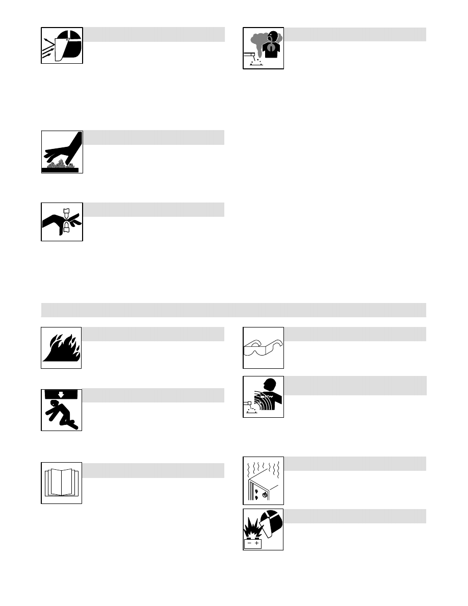
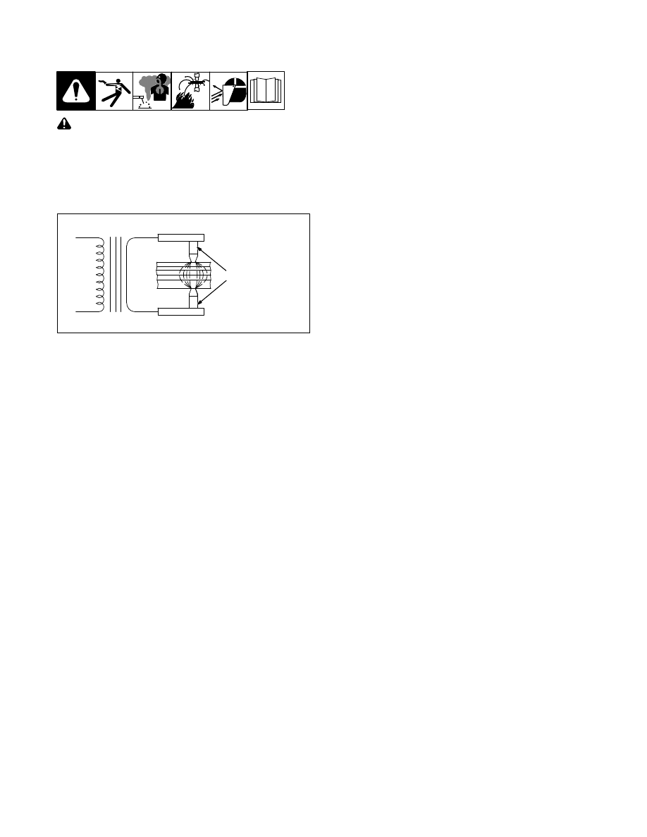
the welding tip contact surfaces. In the illustration below a complete
secondary resistance spot welding circuit is illustrated. For clarity, the
various parts of the resistance spot welding machine are identified.
TONGS
S
P
T
1
ELECTRODE TIPS
TONGS
WORKPIECE
TRANSFORMER
Resistance Spot Welding Machine With Workpiece
SECTION 3 − FUNDAMENTALS OF RESISTANCE SPOT
WELDING
3-1. Principle
Resistance welding is accomplished when current is caused to flow
through electrode tips and the separate pieces of metal to be joined.
The resistance of the base metal to electrical current flow causes
localized heating in the joint, and the weld is made.
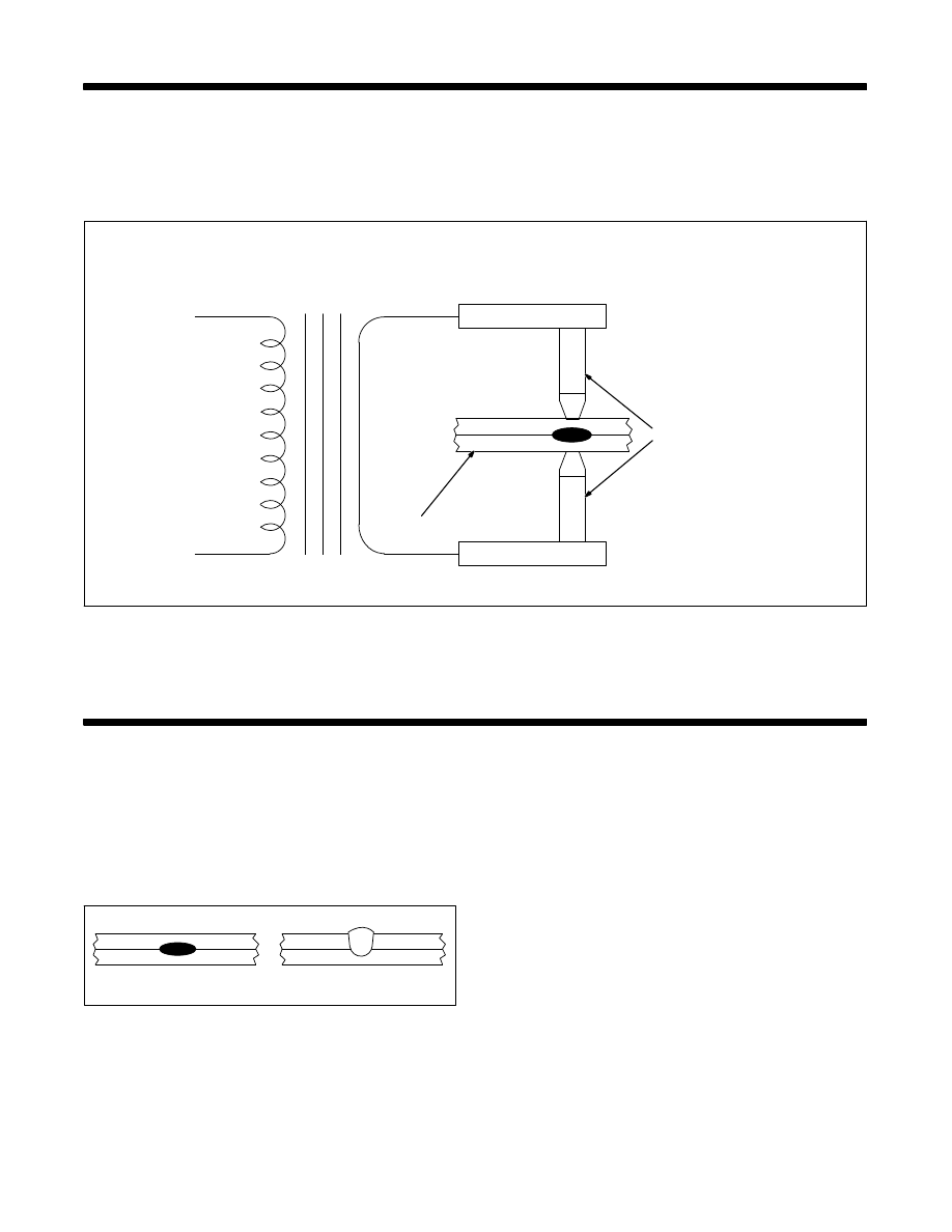
The resistance spot weld is unique because the actual weld nugget
is formed internally in relation to the surface of the base metal.
Figure 4-1 shows a resistance spot weld nugget compared to a gas
tungsten-arc (TIG) spot weld.
ÉÉ
ÉÉ
ÉÉ
RESISTANCE SPOT
TUNGSTEN ARC SPOT
Figure 4-1. Resistance And TIG Spot Weld
Comparison
The gas tungsten-arc spot is made from one side only. The
resistance spot weld is normally made with electrodes on each side
of the workpiece. Resistance spot welds may be made with the
workpiece in any position.
The resistance spot weld nugget is formed when the interface of the
weld joint is heated due to the resistance of the joint surfaces to
electrical current flow. In all cases, of course, the current must flow or
the weld cannot be made. The pressure of the electrode tips on the
workpiece holds the part in close and intimate contact during the
making of the weld. Remember, however, that resistance spot
welding machines are NOT designed as force clamps to pull the
workpieces together for welding.
3-2. Heat Generation
A modification of Ohm’s Law may be made when watts and heat are
considered synonymous. When current is passed through a
conductor the electrical resistance of the conductor to current flow
will cause heat to be generated. The basic formula for heat
generation may be stated:
H = I
2
R
H = Heat
I
2
= Welding Current Squared
R = Resistance
The secondary portion of a resistance spot welding circuit, including
the parts to be welded, is actually a series of resistances. The total
additive value of this electrical resistance affects the current output of
the resistance spot welding machine and the heat generation of the
circuit.
The key fact is, although current value is the same in all parts of the
electrical circuit, the resistance values may vary considerably at
different points in the circuit. The heat generated is directly
proportional to the resistance at any point in the circuit.

003 335 Page 5
HEAT OR
WELD TIME
OFF
TIME
HOLD
TIME
SQUEEZE
TIME
START
Figure 4-2. Spot Welding Time Cycle
Squeeze Time
Time between pressure application and weld.
Heat Or Weld Time
Weld time in cycles.
Hold Time
Time that pressure is maintained after weld is made.
Off Time
Electrodes separated to permit moving of material for next spot.
Resistance spot welding machines are constructed so minimum
resistance will be apparent in the transformer, flexible cables, tongs,
and electrode tips. The resistance spot welding machines are
designed to bring the welding current to the weldment in the most
efficient manner. It is at the weldment that the greatest relative
resistance is required. The term “relative” means with relation to the
rest of the actual welding circuit.
There are six major points of resistance in the work area. They are
as follows:
1. The contact point between the electrode and top workpiece.
2. The top workpiece.
3. The interface of the top and bottom workpieces.
4. The bottom workpiece.
5. The contact point between the bottom workpiece and the
electrode.
6. Resistance of electrode tips.
The resistances are in series, and each point of resistance will retard
current flow. The amount of resistance at point 3, the interface of the
workpieces, depends on the heat−transfer capabilities of the material, the
material’s electrical resistance, and the combined thickness of the
materials at the weld joint. It is at this part of the circuit that the nugget of
the weld is formed.
3-3. The Time Factor
Resistance spot welding depends on the resistance of the base metal
and the amount of current flowing to produce the heat necessary to
make the spot weld. Another important factor is time. In most cases
several thousand amperes are used in making the spot weld. Such
amperage values, flowing through a relatively high resistance, will create
a lot of heat in a short time. To make good resistance spot welds, it is
necessary to have close control of the time the current is flowing.
Actually, time is the only controllable variable in most single impulse
resistance spot welding applications. Current is very often economically
impractical to control. It is also unpredictable in many cases.
Most resistance spot welds are made in very short time periods. Since
alternating current is normally used for the welding process, procedures
may be based on a 60 cycle time (sixty cycles = 1 second). Figure 4-2
shows the resistance spot welding time cycle.
Previously, the formula for heat generation was used. With the addition
of the time element, the formula is completed as follows:
H = I
2
RTK
H = Heat
I
2
= Current Squared
R = Resistance
T = Time
K = Heat Losses
Control of time is important. If the time element is too long, the base
metal in the joint may exceed the melting (and possibly the boiling)
point of the material. This could cause faulty welds due to gas
porosity. There is also the possibility of expulsion of molten metal
from the weld joint, which could decrease the cross section of the
joint and weaken the weld. Shorter weld times also decrease the
possibility of excessive heat transfer in the base metal. Distortion of
the welded parts is minimized, and the heat affected zone around the
weld nugget is substantially smaller.
3-4. Pressure
The effect of pressure on the resistance spot weld should be carefully
considered. The primary purpose of pressure is to hold the parts to be
welded in intimate contact at the joint interface. This action assures
consistent electrical resistance and conductivity at the point of weld. The
tongs and electrode tips should NOT be used to pull the workpieces
together. The resistance spot welding machine is not designed as an
electrical “C” clamp! The parts to be welded should be in intimate
contact BEFORE pressure is applied.
Investigations have shown that high pressures exerted on the weld joint
decrease the resistance at the point of contact between the electrode tip
and the workpiece surface. The greater the pressure the lower the
resistance factor.
Proper pressures, with intimate contact of the electrode tip and the base
metal, tend to conduct heat away from the weld. Higher currents are
necessary with greater pressures and, conversely, lower pressures
require less amperage from the resistance spot welding machine. This
fact should be carefully noted, particularly when using a heat control with
the various resistance spot welding machines.
3-5. Electrode Tips
Copper is the base metal normally used for resistance spot welding
tongs and tips. The purpose of the electrode tips is to conduct the
welding current to the workpiece, to be the focal point of the pressure
applied to the weld joint, and to conduct heat from the work surface. The
tips must to maintain their integrity of shape and characteristics of
thermal and electrical conductivity under working conditions.
Electrode tips are made of copper alloys and other materials. The
Resistance Welders Manufacturing Association (RWMA) has classified
electrode tips into two groups:
Group A − Copper based alloys
Group B − Refractory metal tips
The groups are further classified by number. Group A, Class I, II, III, IV,
and V are made of copper alloys. Group B, Class 10, 11, 12, 13, and 14
are the refractory alloys.
Group A, Class I electrode tips are the closest in composition to pure
copper. As the Class Number goes higher, the hardness and annealing
temperature values increase, while the thermal and electrical conductivity
decreases.
Group B compositions are sintered mixtures of copper and tungsten,
etc., designed for wear resistance and compressive strength at high
temperatures. Group B, Class 10 alloys have about 40 percent the
conductivity of copper with conductivity decreasing as the number value
increases. Group B electrode tips are not normally used for applications
in which resistance spot welding machines would be employed.
003 335 Page 6
3-6. Practical Uses Of Resistance
Spot Welding
Spot Welding can be hazardous. Read and follow the Safety
information at front of this book. Also read and follow the
equipment labels and owner’s manual carefully.
As current density is increased, the weld time is decreased
proportionately. If, however, the current density becomes too high, there
is the possibility of expelling molten metal from the interface of the joint
thereby weakening the weld. The ideal time and current density condition
is somewhere just below the level of causing metal to be expelled.
ELECTRODE TIPS
TONGS
TONGS
S
P
T
1
Figure 4-3. Resistance Spot Weld Heat Zones
It is apparent that the heat input cannot be greater than the total
dissipation rate of the workpiece and the electrode without having metal
expelled from the joint.
Thoughts have changed concerning the flow of current through the
workpiece. Previously, current was considered to flow in a straight line
through the weld joint. This is not necessarily true when multiple
thicknesses of material are being welded.
The characteristic is for the current to “fan out”, thereby decreasing the
current density at the point of weld the greatest distance from the
electrode tips. The illustration (Figure 4-3) shows the resistance spot
weld heat zones for several thicknesses of metal. Note that the
uncontrollable variables (such as interface contamination) are multiplied
when resistance spot welding several thicknesses of material. Quality
levels will be much lower for “stack” resistance spot welding, which
explains why such welding practices are avoided whenever possible.
Disregarding the quality factor, it becomes apparent that the number of
thicknesses of a material which may be successfully resistance spot
welded at one time will depend on the material type and thickness as
well as the KVA capacity of the resistance spot welding machine.
KVA rating, duty cycle, and other pertinent information is shown on all
resistance spot welding machine nameplates. The catalog literature and
the operating manuals provide data on the maximum combined
thicknesses of material that each unit can weld. A table showing the
various models of resistance spot welding machines is located in the
back of this book.
3-7. Electrode Tip Size
When you consider that it is through the electrode that the welding
current is permitted to flow into the workpiece, it is logical that the size of
the electrode tip point controls the size of the resistance spot weld.
Actually, the weld nugget diameter should be slightly less than the
diameter of the electrode tip point. If the electrode tip diameter is too
small for the application, the weld nugget will be small and weak. If,
however, the electrode tip diameter is too large, there is danger of
overheating the base metal and developing voids and gas pockets. In
either instance, the appearance and quality of the finished weld would
not be acceptable.
Determining electrode tip diameter requires some decisions on the part
of the weldment designer. The resistance factors involved for different
materials will certainly have some bearing on electrode tip diameter
determination. A general formula has been developed for low carbon
steel. It will provide electrode tip diameter values that are usable for most
applications.
The tip diameter discussed in this text refers to the electrode tip
diameter at the point of contact with the workpiece. It does not refer
to the major diameter of the total electrode tip.
The formula generally used for low carbon steel is as follows:
Electrode tip diameter = 0.100 in. + 2t
where “ t ” is the thickness in inches of one thickness of the metal to be
welded. This formula is applicable to the welding of metals of dissimilar
thicknesses. The formula is applied to each thickness individually, and
the proper electrode tip diameter selected for each size of the joint.
For example, if two pieces of 0.062 in. sheet metal are to be joined, the
electrode tip diameter would be the same for both sides of the joint. The
calculation would be as follows:
Electrode tip dia. = 0.100 + 2t
= 0.100 + 2 x 0.062 in.
= 0.100 + 0.124 in.
Electrode tip dia. = 0.224 in.
If the two pieces were unequal in thickness, such as one piece 0.062 in.
and the other 0.094 in., two calculations would have to be made. Each
thickness would be treated as the basis for one electrode tip diameter
determination, as follows:
Electrode tip dia. = 0.100 + 2t
= 0.100 + 2 x 0.062 in.
= 0.100 + 0.124 in.
Electrode tip dia. = 0.224 in. (one side only)
For the other side, the calculation is as follows:
Electrode tip dia. = 0.100 + 2t
= 0.100 + 2 x 0.094 in.
= 0.100 + 0.188 in.
Electrode tip dia. = 0.288 in. (one side only)
Remember that the formula is applicable to low carbon steels and may
not be correct for other materials.
3-8. Pressure Or Welding Force
The pressure exerted by the tongs and the electrode tips on the
workpiece has a great effect on the amount of weld current that flows
through the joint. The greater the pressure, the higher the welding
current value will be, within the capacity of the resistance spot welding
machine.
Setting pressure is relatively easy. Normally, samples of material to be
welded are placed between the electrode tips and checked for adequate
pressure to make the weld. If more or less pressure is required, the
operating manual for the resistance spot welding machine will give
explicit directions for making the correct setting. As part of the equipment
set-up, the tong and electrode tip travel should be adjusted to the
minimum required amount to prevent “hammering” the electrode tips and
tip holders.
3-9. Heat Balance
There is no particular problem of heat balance when the materials to be
welded are of equal type and thickness. The heat balance, in such
cases, is automatically correct if the electrode tips are of equal diameter,
type, etc. Heat balance may be defined as the conditions of welding in
which the fusion zone of the pieces to be joined are subjected to equal
heat and pressure.
When the weldment has parts of unequal thermal characteristics, such
as copper and steel, a poor weld may result for several reasons. The
metals may not alloy properly at the interface of the joint. There may be
a greater amount of localized heating in the steel than in the copper. The
reason would be because copper has low electrical resistance and high
thermal transfer characteristics, while steel has high electrical resistance
and low thermal transfer characteristics.
003 335 Page 7
HIGH RESISTANCE
MATERIAL
COPPER
STEEL
ÉÉÉ
ÉÉÉ
ÉÉÉ
ÉÉÉ
ÉÉÉ
ÉÉÉ
a
b
c
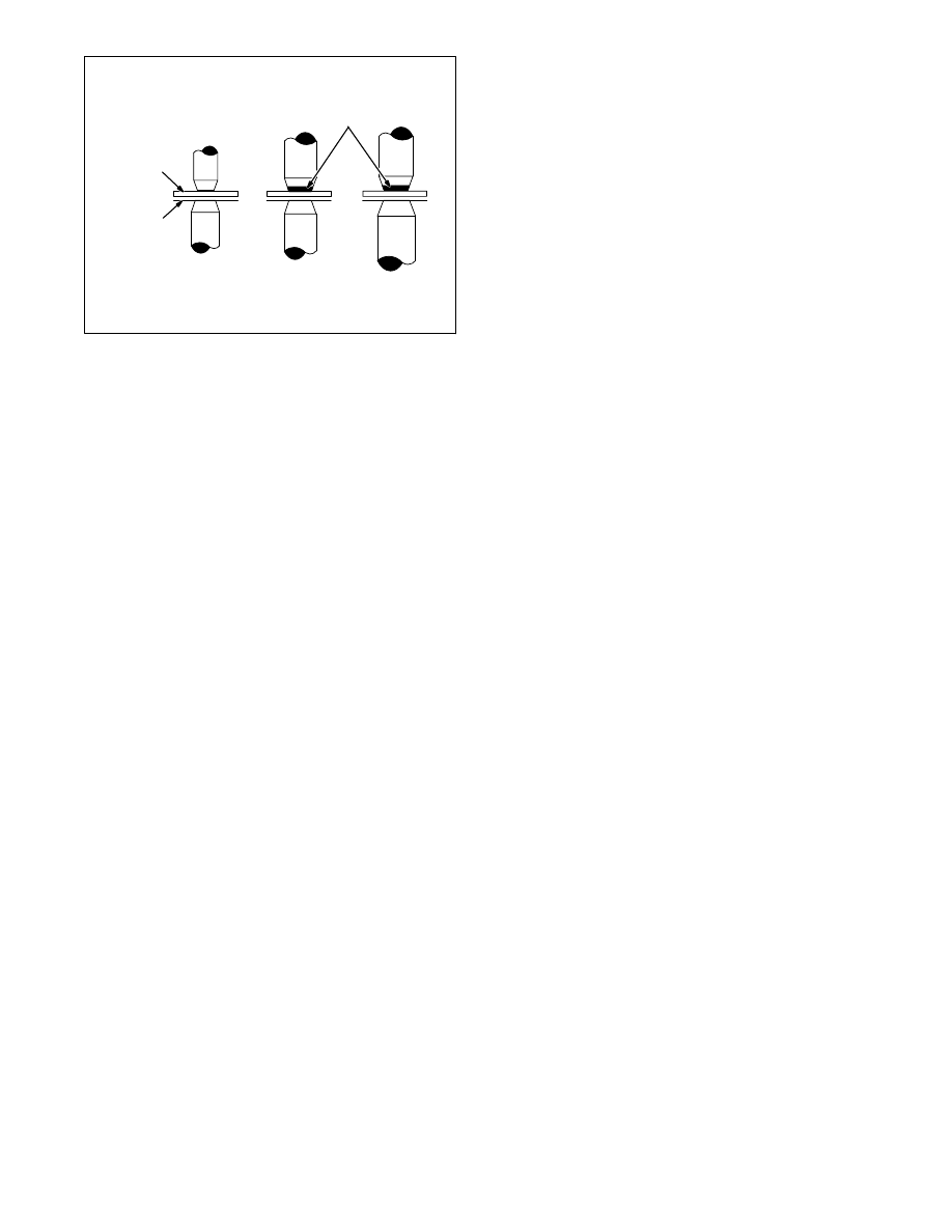
Figure 4-4. Techniques For Obtaining Heat Balance
Correct heat balance may be obtained in a weldment of this type by one
of several methods. Figure 4-4 illustrates three possible solutions to the
problem. Figure 4-4 (a) shows the use of a smaller electrode tip area for
the copper side of the joint to equalize the fusion characteristics by
varying the current density in the dissimilar materials.
Figure 4-4 (b) shows the use of an electrode tip with high electrical
resistance material, such as tungsten or molybdenum, at the contact
point. The result is to create approximately the same fusion zone in the
copper as in the steel. A combination of the two methods is shown in
Figure 4-4 (c).
3-10. Surface Conditions
All metals develop oxides which can be detrimental to resistance spot
welding. Some oxides, particularly those of a refractory nature, are more
troublesome than others. In addition, the mill scale found on hot-rolled
steels will act as an insulator and prevent good-quality resistance spot
welding. Surfaces to be joined by this process should be clean, free of
oxides and chemical compounds, and have a smooth surface.
3-11. Materials Data For Resistance
Spot Welding
This section of the text will consider methods used for resistance spot
welding some of the common metals that are used in fabrication work. It
is not intended that all the possible problems that could arise will be
answered. The purpose of this part of the text is to provide general
operational data for use with resistance spot welding machines. Where
applicable, the data provided will be related to specific models and size
(kVA) of units. The units listed in this section are not recommended
for aluminum or copper alloys.
3-12. Mild Steel
Mild or low-carbon steel comprises the largest percentage of material
welded with the resistance spot welding process. All low-carbon steels
are readily weldable with the process if proper equipment and
procedures are used.
The carbon steels have a tendency to develop hard, brittle welds as the
carbon content increases if proper post-heating procedures are not
used. Quick quenching of the weld, where the nuggets cools rapidly,
increases the probability of hard, brittle micro-structure in the weld. Hot
rolled steel will normally have mill scale on the surface of the metal. This
type of material is usually not resistance spot welded with resistance
welding machines of the kVA ratings of Miller-built units.
Cold rolled steel (CRS) and hot rolled steel, pickled and oiled (HRSP &
O), may be resistance spot welded with very little trouble. If the oil
concentration is excessive on the sheet metal, it could cause the
formation of carbon at the electrode tips thereby decreasing their useful
life. De−greasing or wiping is recommended for heavily oiled sheet
stock.
The resistance spot weld should have shear strength equal to the base
metal shear strength and should exceed the strength of a rivet or a
fusion plug weld of the same cross sectional area. Shear strength is
normally accepted as the criteria for resistance spot weld specifications,
although other methods may be used.
A common practice is to “peel” two welded sample strips apart to see if
a clean “rivet” is pulled from one piece. If it is, the resistance spot
welding condition is considered correct.
With magnetic materials such as mild steel, the current through the weld
can vary substantially depending on how much of the magnetic material
is within the tong loop. The tong loop is sometimes called the “throat” of
the resistance spot welding machine.
For example, the part to be welded may have the largest amount of the
base metal within the throat of the unit for any one resistance spot weld
and almost none of the base metal in the throat for the second spot
weld. The current at the weld joint will be less for the first weld. The
reason is the reactance caused by the ferrous material within the arc
welding circuit.
Resistance spot welding machines are applicable to low carbon steel
welding. For best results, they must be used within their rated
capacity of total thickness of material. They should not be operated
beyond the specified duty cycle or the contactor and transformer
may be damaged. The 50 percent duty cycle for this type of
equipment should be adequate for all applications within their rating.
The RWMA standard rating for general duty resistance welding
machines is 50 percent duty cycle. Duty cycle is based on a 10
second time frame and a 50 percent duty cycle means the unit can
weld 5 seconds out of each 10 second time period without
overheating.
Table 4-1 provides the rating information for all models of resistance spot
welding machines. The open-circuit voltage and short-circuit current for
different tong lengths, etc., are given. The short-circuit current values are
according to RWMA test procedures for copper-to-copper contact. The
values considered do not have weld metal between the tips. The
combined metal thickness that each model can accommodate is also
shown.
3-13. Low Alloy And Medium
Carbon Steels
There are some pertinent differences in resistance spot welding low alloy
and medium carbon steels as compared to mild or low carbon steels.
The resistance factor for the low alloy and medium carbon steels is
higher; therefore, the current requirements are slightly lower. Time and
temperature are more critical since metallurgical changes will be greater
with these alloys. There is certainly more possibility of weld
embrittlement than there is with mild steel.
Resistance spot welding pressures are normally higher with these
materials because of the additional compressive strength inherent in the
low alloy and medium carbon steels. It is always a good idea to use
longer welding times when welding these alloys to retard the cooling rate
and permit more ductile welds.
3-14. Stainless Steels
The chrome-nickel steel alloys (austenitic) have very high electrical
resistance and are readily joined by resistance spot welding. The
consideration of great importance with these materials is rapid cooling
through the critical range, 800
°
F to 1400
°
F. The rapid quench associated
with resistance spot welding is ideal for reducing the possibility of
chromium carbide precipitation at the grain boundaries. Of course, the
longer the weldment is held at the critical temperatures, the greater the
possibility of carbide precipitation.
003 335 Page 8
3-15. Steels, Dip Coated Or Plated
The overwhelming majority of material in this category is galvanized, or
zinc-coated steel. Although some galvanized steel is electroplated, the
dip-coated steel costs less and is predominantly used. The zinc coating
is uneven in thickness on dip-coated steel. The resistance factor will
vary from weld to weld, and it is very difficult to set conditions in chart
form for the material.
It is impossible to maintain the integrity of the galvanized coating when
resistance spot welding. The low melting point of the zinc coating,
compared to the fusion temperature of the steel sheet, causes the zinc
to vaporize. Of course, there must be adequate pressure to force the
zinc aside at the weld interface to permit steel-to-steel fusion. Otherwise,
the strength of the resistance spot weld is open to question.
Materials are available to repair the external damage to the coating that
may be incurred because of the welding heat. There is no remedy for
the loss of coating material at the interfaces of the weld, unfortunately. In
fact, the vaporization of the zinc can cause porosity in the weld and a
general weakening of the expected shear strength.
Do not weld on coated metals, such as galvanized, lead, or
cadmium plated steel, unless the coating is removed from the
weld area, the area is well ventilated, and while wearing an
air-supplied respirator. The coatings and any metals
containing these elements can give off toxic fumes if welded.
Wear protective garments such as oil-free, flame-resistant
leather gloves, heavy shirt, cuffless trousers, high shoes, and
a cap. Synthetic material usually does not provide such
protection.
Other coated material, such as terne plate (lead coated) may have
varying degrees of toxicity. Adequate ventilation is mandatory when
working with these materials.
The vaporization of the coating material has a tendency to foul the
electrode tips. The tips should be cleaned frequently to prevent the
alloying of the lower melting materials with the copper tips. The tips may
require cleaning and dressing every fourth or fifth weld to maintain
quality in the product, although for some galvanized applications the best
welds are made after several spots blacken the tips. The use of short
weld times will increase the possibility of good welds with the least
amount of tip fouling.
3-16. Aluminum And Aluminum Alloys
Resistance spot welding machines with kVA ratings much greater than
20 kVA are necessary to make sound welds on most aluminum
materials and any other high−conductivity type of base metal. The
electrical conductivity of aluminum is high, and welding machines must
provide high currents and exact pressures in order to provide the heat
necessary to melt the aluminum and produce a sound weld.
3-17. Summary
Resistance spot welding is a welding technique that is used for almost
all known metals. The actual weld is made at the interface of the parts to
be joined. The electrical resistance of the material to be welded causes
a localized heating at the interfaces of the metals to be joined. Welding
procedures for each type of material must be developed for the most
satisfactory results.
It is possible that shunt currents flowing through a previously made spot
weld will take welding current away from the second second spot weld
to be made. This will occur if the two spot welds are too close together,
and it will happen with all metals.
The following table is intended as a guide for setting up resistance spot
welding procedures. The exact time, pressure, and current setting will
depend on the specific application and the kVA rating of the resistance
spot welding machine employed.
Table 4-1. Resistance Spot Welding Machine
Specifications
Model
KVA
Rating
Rated
Output
6 in.
Tongs
Rated
Output
12 in.
Tongs
Rated
Output
18 in.
Tongs
Open
Circuit
Voltage
Max. Capacity**
Uncoated Mild Steel,
Combined Thickness
Using 6 in. Tongs
MSW-41
1.5
5,550
4,500
3,600
1.6
1/8 in.
MSW-41t*
1.5
5,550
4,500
3,600
1.6
1/8 in.
LMSW-52
2.5
6,750
5,800
4,850
2.5
3/16 in.
LMSW-52t*
2.5
6,750
5,800
4,850
2.5
3/16 in.
SSW-2020
20
12,500
10,500
9,000
3.55
1/4 in.
SSW-2040
20
12,500
10,500
9,000
3.55
1/4 in.
* “t” series feature an automatic timer.
** Ratings are for uncoated mild and low carbon steel with 6 in. tongs. For other
metals, the combined thickness will have to be determined.
The following general data is provided to assist the operator in setting up
welding procedures when using any of the resistance spot welding
machines listed in Table 4-1.
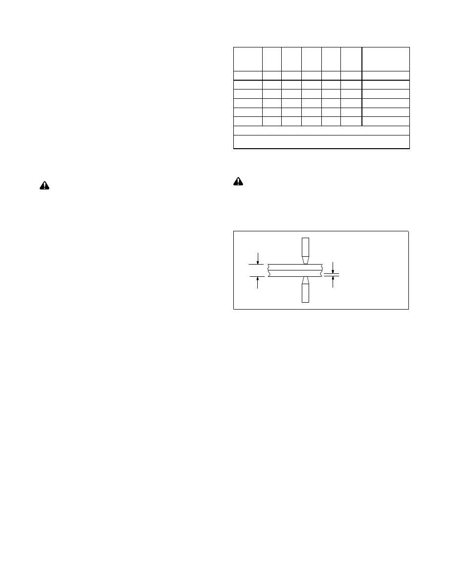
Turn off unit and disconnect input power.
1. Close tongs and measure space between electrode tip contact
surfaces.
2. Measure the thickness of the total weldment.
3. Adjust tong gap to measurement of Step 2 less 1/2 the thickness of
the thinnest workpiece to be welded.
X − Y = Tong Gap
X
Y
4. Insert the parts to be welded between the electrode tips and
bring tips to welding pressure. There should be a slight deflection
of the tongs. This may be measured with a straight edge set on
the tong longitudinal axis.
5. Energize the spot welding machine and make a sample weld.
6. Test the weld by visual and mechanical means. Check the
electrode tip for deformation and contamination
(see Test Procedures).
7. Adjust tong pressure as required
(see equipment manual for tong adjustment procedures).
3-18. Test Procedures
The test procedures outlined are very simple and require a minimum of
equipment to perform.
1. Visual Test
Observe the deformation and shape of the surface contact points at
both sides of the weld.
Excessive “dishing” of the surface contact point indicates one or
more of the following:
a. Excessive tong pressure.
b. Weld time too long.
c. Misalignment of the electrode tips.
If the resistance spot weld does not have an even, concentric
surface appearance, the problem could be misalignment of the
electrode tips. Align electrode tips with the power off and a typical
weld joint between the tip surfaces.
2. Mechanical Test
Place one end of the resistance spot weld sample in vice jaws. Use
mechanical means to force the weld apart. One side of the weld
should pull loose from the parent metal with a metal extension from
the weld. Check for proper weld diameter.
003 335 Page 9
SECTION 4 − MAINTENANCE AND TROUBLESHOOTING
4-1. Maintenance
!
Disconnect power before maintaining.
During heavy service, maintain monthly.
= Check = Change = Clean = Replace
* To be done by Factory Authorized Service Agent
Reference
Every
3
Months
- Oil unit
- Inspect Tips
− Replace Damaged
or
Unreadable Labels
See Owners Manual
Every
6
Months
During
Heavy
Service,
Clean
Monthly
OR
− Blow Off Or Vacuum
Unit
See Owners Manual
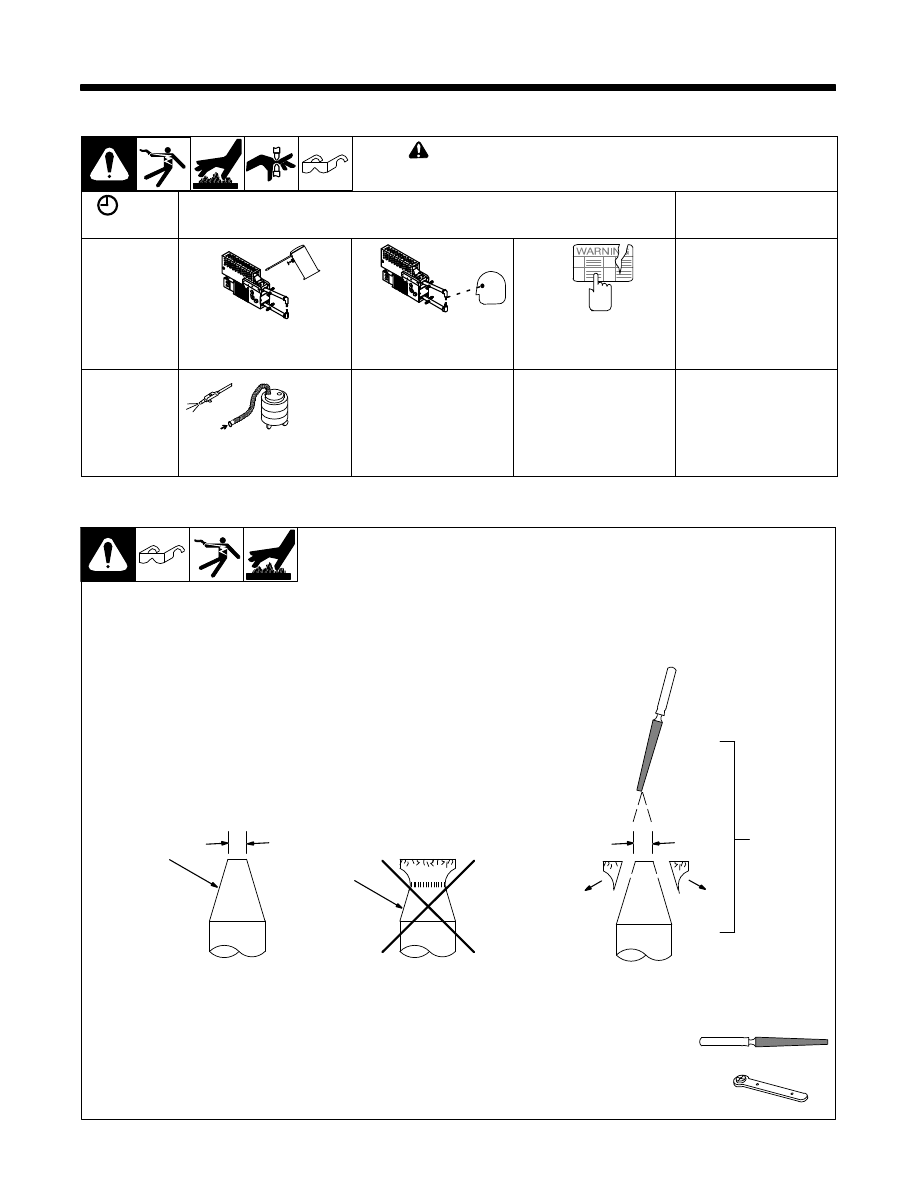
4-2. Dressing Tips
1
New Tip
2
Used Tip Requiring Dressing
3
Dressing Method − Keep top
diameter same as a new tip.
1
2
3
d
d
OR
Tools Needed:
Diameter “d” equals 3/16 − 1/4 in. (4.8 − 6.4 mm).
003 335 Page 10
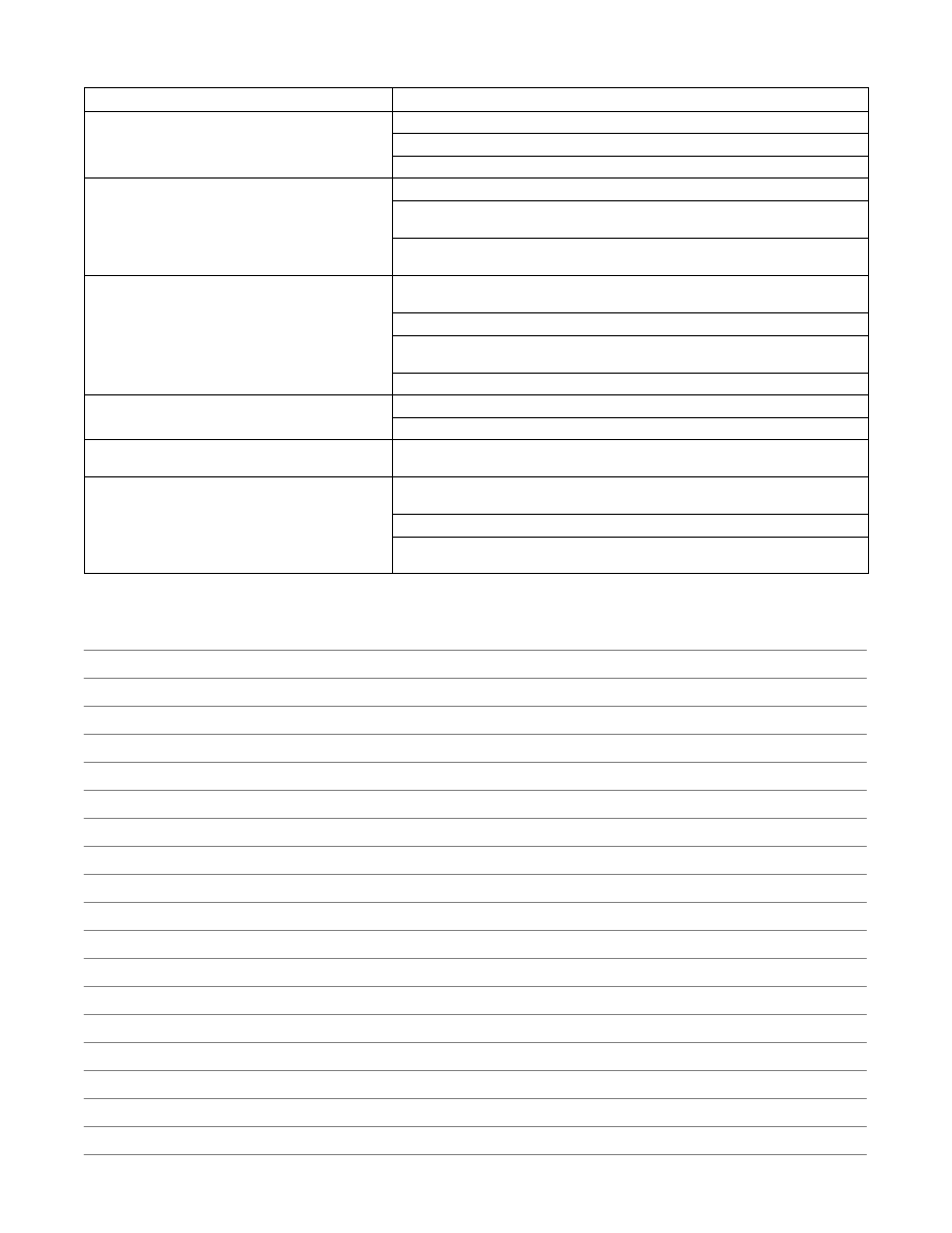
4-3. Troubleshooting
Trouble
Remedy
Tips overheating.
Not enough tong pressure. Increase tong pressure.
Weld time too long. Reduce weld time.
Material too thick for the spot welding machine.
Tips arcing on material.
Not enough tong pressure. Increase tong pressure.
Tips not aligned correctly. Realign tips or dress tips to proper diameter (see Section
Base material may be welded to tips causing high resistance and poor electrical
current flow. Clean or dress tips (see Section 4-2).
Spatter or molten material being expelled out during
welding operation.
Incorrect tip alignment. Dress tips so that they align and are flat on the material (see
Excessive tong pressure. Reduce tong pressure.
Output amperage too high. Reduce amperage setting, if applicable (not available on
air-cooled models).
Weld time too long. Reduce weld time.
Inconsistent weld nugget.
Inconsistent weld time. Install a weld timer, if applicable.
Not enough tong pressure. Increase tong pressure.
Hole in middle of weld.
Contact area of tips is too large. Change to a smaller tip diameter or dress tips back
to original diameter (see Section 4-2).
Poor weld or no weld at tips.
Material too thick for spot welding machine. Check that material thickness is within
capacity of spot welding machine.
Tongs are too long. Reduce tong length.
Remove coating from material for intimate contact between pieces. Remove oxides
and chemical compounds including galvanized coating.
Notes

Notes

Notes

Notes

ORIGINAL INSTRUCTIONS − PRINTED IN USA
©
2012 Miller Electric Mfg. Co.
Miller Electric Mfg. Co.
An Illinois Tool Works Company
1635 West Spencer Street
Appleton, WI 54914 USA
International Headquarters−USA
USA Phone: 920-735-4505 Auto-Attended
USA & Canada FAX: 920-735-4134
International FAX: 920-735-4125
For International Locations Visit
www.MillerWelds.com
Wyszukiwarka
Podobne podstrony:
Control and Power Supply for Resistance Spot Welding (RSW)
Handbook for Radiological Monitors
Ultimate Handbook for Beginners
Sailing Introductory Handbook For Sailing Boats
a grounded theory for resistance to change in small organization
Handbook for Radiological Monitors
Handbook for Successful VoIP Deployment
connection diagram of spot welding tc10 tc 15
Handbook for the New Paradigm by George Green
Babauta Leo Zen Habits Handbook for Life
Handbook for Working with Defendants and Offenders with Mental Disorders Third Edition
Pager Handbook for the Radio Amateur
commanders handbook for antiterrorism readiness
handbook for strategic planning
A Handbook for the Mechanical Designer
Handbook for Calculus Instructors WW
Teaching Pronunciation a handbook for Teachers and Trainers
A Handbook for Technical Writers and Editors
circuit diagram of spot welding machine (tc15tc20)
więcej podobnych podstron