
3
Thermodynamics and
Electrochemical
Kinetics
3.1
The First Law of Thermodynamics
• The Second Law of
Thermodynamics
• The Increase in Entropy Principle • Heat
Engines and the Carnot Cycle
• Exergy and the Decrease in
Exergy Principle
3.2
Conversion Efficiencies of Heat Engines and Fuel Cells
Maximum Thermal Efficiencies
• Second Law Efficiency
3.3
Adiabatic Flame Temperature
• Exergy Loss Caused by a
Temperature Rise
3.4
Criterion for a Spontaneous Reaction
• The Effect of
Temperature and Pressure on
∆G • Equilibrium of a Gas
Mixture
• Maximum Work • The Nernst Equation and Open
Circuit Potential
3.5
Electrode Kinetics
• Single-Step Electrode Reactions • The
Butler-Volmer Equation
3.6
Notation for Section 3.1
Greek
• Subscripts • Superscript
Notation for Section 3.4
Greek
• Subscripts • Superscripts
Notation for Section 3.5
Greek
• Subscripts
A thermodynamic analysis of fuel cells and heat engines shows that an energy conversion process
that occurs at constant temperature is more efficient than a process that relies on large temperature
differences. This chapter explains the fundamental principles of engineering thermodynamics, chem-
ical thermodynamics, and electrode kinetics. The thermodynamics section shows that the ideal fuel
cell is a less irreversible energy conversion device. The section on engineering thermodynamics
covers the First and Second Laws of Thermodynamics, heat engines and the Carnot cycle, entropy
and exergy, efficiencies based on the First and Second Laws, and exergy loss during heat generation.
The chemical thermodynamics section is based on the change in Gibbs energy, which is used to
derive the Nernst equation.
Eric Chen
University of Oxford
© 2003 by CRC Press LLC

Although thermodynamics establishes the theoretical maximum performance of an energy conversion
device, reaction rates describe the actual performance. For instance, a fuel cell at open circuit — a
condition of chemical equilibrium at the electrodes — would give a maximum voltage but would not
produce power because no net flow of electrons between the electrodes would occur. To produce elec-
tricity, the electrodes are polarized to move the reactions away from equilibrium. In the electrode kinetics
section, a derivation is presented for the rate for a single-step electrochemical reaction, which is expressed
by the Butler–Volmer equation.
3.1 Engineering Thermodynamics
Thermodynamics is the study of the conversion of energy from one form to another. Usually, the goals
are to produce heat or to do work, which could be either electrical or mechanical in form. The source
of energy is fuel, in which the energy is bound in chemical form. Devices such as fuel cells and heat
engines release the energy by chemical reactions, converting it into electricity or heat. Electricity is
converted to work by an electrical circuit or an electromagnetic device such as a motor; heat is converted
to work by a mechanical device such as a piston-cylinder or a turbine.
The Laws of Thermodynamics limit the quantity and quality of energy as it changes states within an
energy conversion device. The First Law states that, although the form of energy may change, the quantity
of energy in a system remains the same. The Second Law, using the entropy property, establishes the
direction in which reactions may proceed, the concept that energy possesses a quality, and a theoretical
limit of energy conversion efficiency. This section reviews the thermodynamic principles related to heat
engines to show that the irreversibilities associated with combustion make the energy conversion process
in these devices less efficient than one that occurs at constant temperature.
3.1.1 The First Law of Thermodynamics
The First Law of Thermodynamics states that the energy of a system is conserved. Energy is neither lost
nor generated but is converted from one form to another. Energy in the form of heat or work passes
through the boundaries of the system and affects the total energy of the system.
(3.1)
Equation (3.1) uses the sign convention of positive for input and negative for output: Q is the heat
entering the system, –W is the work leaving (performed by) the system, and E is the total energy of the
system. A change in heat or work is expressed by an inexact differential,
δ, because the values are
dependent on path and are therefore called path functions. Energy is a property and is a point function,
dependent only on the initial and final states. When Eq. (3.1) is integrated, the First Law relation becomes
(3.2)
For a closed system (e.g., a piston-cylinder), also called a control mass (a system that does not involve
mass flow), the change in the total energy is shown in Eq. (3.3) as the sum of the changes in internal,
U, kinetic, KE, and potential, PE, energies.
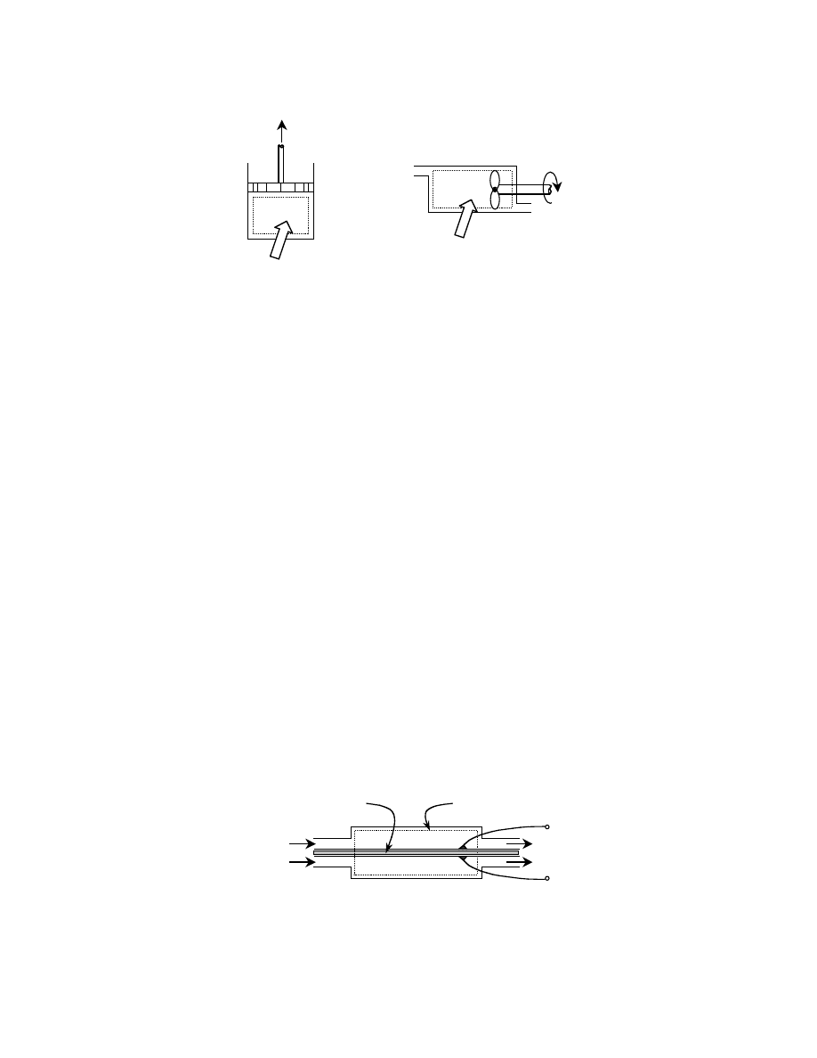
shows a piston-cylinder as an example of a
control mass.
(3.3)
For a control volume (e.g., a steam turbine), which is an open system that does involve the flow of
mass across its boundaries, an additional term is added to the total energy. This term, PV, where P is the
pressure and V is the volume of the fluid, reflects the work that is exerted on the fluid to keep it flowing.
shows a control volume. The property enthalpy, H, defined in Eq. (3.4), accounts for the
flow work.
δQ δW
–
dE
=
Q
W
–
∆E
=
∆E
∆U ∆KE ∆PE
+
+
=
© 2003 by CRC Press LLC
(3.4)
So for a stationary control volume under steady-flow conditions (
∆KE = ∆PE = 0, properties constant
with time), the First Law is written with the change in enthalpy in Eq. (3.5).
(3.5)
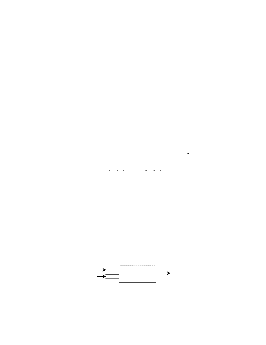
A fuel cell may be represented by a control volume as shown in
, allowing the use of Eq.
(3.5) for the thermodynamic analysis. Rather than the work taking the form of volumetric expansion
as in a cylinder or of shaft rotation as in a turbine, the work is in the form of electron transport across
a potential difference.
3.1.2 The Second Law of Thermodynamics
The Second Law of Thermodynamics defines the property entropy, which can be used as a measure of
the disorder in a system. A process that does not generate entropy is called a reversible process if it can
be performed and then returned to its initial state (reversed) without leaving any traces on the surround-
ings. Therefore, in a reversible process, by the First Law, no net exchange of heat or work occurs in either
the system or surroundings: both return to their original states. An irreversible process, on the other
hand, does generate entropy because of, for example, uncontrolled expansion, heat loss from friction, or
heat transfer through a finite temperature difference. A process involving heat transfer can be made
reversible if the finite temperature difference, or temperature gradient, is minimized to an infinitesimal
difference (at the expense of the rate of heat transfer). Entropy is based on this reversible heat transfer,
and as a property, is expressed as an exact differential in Eq. (3.6).
(3.6)
FIGURE 3.1 (a) The piston-cylinder as an example of a control mass. (b) A control volume, which could represent
a steam turbine.
FIGURE 3.2 A fuel cell represented as a control volume. E stands for electrical potential, measured in volts. (With
permission from Chen, E.L. and Chen, P.I., Proceedings of the ASME 2001 IMECE, vol. 3, Nov. 11–16, 2001.)
Q
W
Q
W
control mass
control
volume
(a)
(b)
H
U
PV
+
=
Q
W
–
∆H
=
dS
δQ
T
-------
rev
=
−E
+E
fuel
oxidant
electrolyte
system boundary
© 2003 by CRC Press LLC

The change in entropy is dependent only on the initial and final states of the system, as seen in the
integrated form of this equation in Eq. (3.7).
(3.7)
For a process that undergoes reversible heat transfer, Q
rev
, at a constant temperature, T
o
, entropy is
expressed as in Eq. (3.8).
(3.8)
3.1.3 The Increase in Entropy Principle
The Clausius inequality of Eq. (3.9), formulated by the German scientist R.J.E. Clausius (in 1865), led
to the discovery of the property, entropy.
(3.9)
For a process that begins at state 1, goes to state 2, and then returns to 1, the cyclic integral may be separated
into steps 1–2 and 2–1. Supposing that the step 2–1 occurs reversibly within the system, denoted by int rev,
then the second term is equivalent to Eq. (3.6), and the property entropy may be substituted.
(3.10)
For an isolated system that, by definition, has no transfer of heat, work, or mass across its boundary,
the term
δQ is zero, and the entropy change will be greater than or equal to zero.
(3.11)
Equation (3.11) is known as the Increase in Entropy Principle and is universally applicable because
all systems, whether open or closed, may be made isolated by extending the system boundary to a
sufficiently great size. Equation (3.12) can be applied to any system once it is made isolated.
(3.12)
The equality sign applies to a reversible process and the inequality sign to an irreversible process.
Therefore, a direction is established: the change in entropy is zero at best for a reversible process and is
positive for a realistic, irreversible process.
Equation (3.13) is a general expression based on Eq. (3.12) that applies to both open and closed
systems, separating the entropy change into components of the system,
∆S
sys
, and of the surroundings,
∆S
surr
. S
gen
is the total change in entropy of both the system and surroundings.
(3.13)
∆S
S
2
S
1
–
δQ
T
-------
rev
1
2
∫
=
=
∆S
Q
rev
T
o
---------
=
δQ
T
-------
∫°
0
≤
δQ
T
-------
1
2
∫
δQ
T
-------
int rev
2
1
∫
+
0
≤
∆S
δQ
T
-------
1
2
∫
≥
∆S 0
≥
∆S
isolated
0
≥
S
gen
∆S
total
∆S
sys
∆S
surr
+
=
=
0
≥
© 2003 by CRC Press LLC

Considering a chamber in which a chemical reaction takes place, the system is a control volume with
mass flowing across its boundaries. Therefore, the entropy change for the system is the difference between
the entropy of the products, S
P
, and the reactants, S
R
, with N representing the number of moles of each
component in the reaction.
(3.14)
Any heat produced or consumed in the reaction is included in the expression for the surroundings,
where Q
surr
is the heat transferred from the system to the surroundings, and T
o
is the temperature of the
surroundings, as shown in Eq. (3.15).
(3.15)
Equation (3.16) is the entropy generated in the reaction, which is the sum of Eqs. (3.14) and (3.15).
(3.16)
3.1.4 Heat Engines and the Carnot Cycle
A heat engine is defined by four requirements. It
1. Receives heat from a high-temperature source (e.g., coal furnace, nuclear reactor)
2. Converts part of this heat to work (e.g., by a turbine)
3. Rejects the remaining waste heat to a low-temperature sink (e.g., atmosphere, river)
4. Operates on a thermodynamic cycle
The steam power plant fits most closely the definition of a heat engine, receiving heat from an external
combustion chamber, extracting work by a turbine, and rejecting heat to a condenser. In contrast, internal
combustion engines such as spark-ignition and diesel engines as well as gas turbines are “open” and
therefore do not satisfy the requirement of operating on a thermodynamic cycle because the working
fluid is continually replaced; the combustion gas is exhausted into the atmosphere and a fresh charge of
air is scavenged for the next mechanical cycle.
For a cyclic process, the initial and final states are identical, so the First Law relation of Eq. (3.2)
involves only the heat input and work output terms, as in Eq. (3.17).
(3.17)
Therefore, the net work that the system can perform is related to the net heat flow that enters the system.
(3.18)
According to the definition of a heat engine, at least two thermal reservoirs are involved in the cycle,
with heat entering the system from the high-temperature reservoir and heat exiting the system to the
low-temperature reservoir. The net work, W
net
, in Eq. (3.19) is the difference between the heat input, Q
in
,
and heat output, Q
out
, of the system.
(3.19)
The thermal efficiency,
η
th
, of a heat engine is determined by the amount of work converted from the
amount of energy input into the system.
∆S
sys
S
P
S
R
–
ΣN
P
s
P
ΣN
R
s
R
–
=
=
∆S
surr
Q
surr
T
o
----------
=
S
gen
S
P
S
R
–
(
)
sys
Q
surr
T
o
----------
+
=
Q
W
–
∆E
0
=
=
W
Q
=
W
net
Q
in
Q
out
–
=
© 2003 by CRC Press LLC
(3.20)
The greater the net work of the system, the higher the conversion efficiency. To achieve the maximum
possible work in a heat engine, all of the processes should be conducted in a reversible manner. An
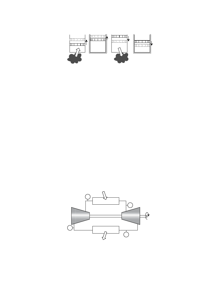
idealized cycle proposed by the French scientist, Sadi Carnot, in 1824, involves four reversible processes
and is known as the Carnot cycle; it is depicted in
with a piston in a cylinder and in
steady-flow devices.
Because heat addition and heat rejection are performed reversibly and isothermally, Eq. (3.15), mod-
ified to give Eq. (3.21), can be used to determine the efficiency of the cycle. Equation (3.22) is the heat
addition step (step 1–2), and Eq. (3.23) is the heat rejection step (step 3–4).
(3.21)
(3.22)
(3.23)
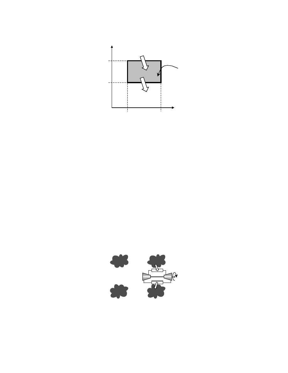
The cycle is represented as a thermodynamic cycle in
, which shows that during the reversible
adiabatic processes, steps 2–3 and 4–1, the entropy remains the same. The figure also shows that the
difference between the heat input, Q
in
, and the heat output, Q
out
, is the net work, W
net
, indicated by the
shaded area.
FIGURE 3.3 The four stages of the reversible Carnot cycle: (1–2) isothermal expansion, (2–3) adiabatic expansion,
(3–4) isothermal compression, (4–1) adiabatic compression.
FIGURE 3.4 The Carnot cycle represented by steady-state, steady-flow devices. All processes are reversible.
Qin
Q
out
1
2
3
2
3
4
4
1
T
H
T
L
η
th
W
net
Q
in
----------
Q
in
Q
out
–
Q
in
-----------------------
1
Q
out
Q
in
---------
–
=
=
=
Q
rev
T
o
∆S
=
Q
in
Q
1
2
T
H
S
2
S
1
–
(
)
=
=
Q
out
Q
3
4
–
T
L
S
3
S
4
–
(
)
=
=
turbine
condenser
combustor
compressor
1
2
3
4
Q
in
Q
out
W
net
© 2003 by CRC Press LLC
The entropy terms in Eqs. (3.22) and (3.23) are identical, and substituting the expressions into Eq.
(3.20) results in Eq. (3.24), the thermal efficiency for the Carnot cycle. Because all of the processes are
reversible, the Carnot cycle is the most efficient heat engine, and Eq. (3.24) is the maximum possible
conversion efficiency for any heat engine.
(3.24)
3.1.5 Exergy and the Decrease in Exergy Principle
The Carnot cycle efficiency is an application of the Second Law of Thermodynamics, establishing the
upward bound for the amount of useful work a heat engine can produce from heat. With the maximum
conversion efficiency established, it is possible to consider the high-temperature reservoir itself as a source
of work. By itself, the reservoir at high temperature, T
H
, in
could be seen as having the potential
to do work if it could transfer heat to a heat engine (the type in
. The potential
to do work is embodied in a property called exergy. Exergy is the term used to quantify the work potential
of a system from its initial state to the dead state, which is the state of the environment, usually at standard
temperature and pressure (STP, 25°C and 1 atm). (The dead state could be at any reference state.)
Besides the work potential of temperature, exergy also applies to pressure because the pressure could
be relieved through a turbine, which would convert the pressure to shaft work. Temperature and pressure
together define a state, which has its associated properties, so properties such as internal energy and
FIGURE 3.5 The Carnot cycle shown on a T-s diagram.
FIGURE 3.6 The high-temperature reservoir, T
H
, in (a) has the potential to do work if a heat engine is placed in
between it and the environment, as in (b), using heat from T
H
and rejecting waste heat to the environment, T
L
.
s
T
s
1
=
s
4
s
2
=
s
3
T
T
L
T
H
1 2
3
4
Q
in
Q
out
W
net
η
th,Carnot
1
T
L
T
H
------
–
=
(a)
(b)
T
H
T
L
T
L
T
H
© 2003 by CRC Press LLC

enthalpy also have a work potential. In this section, the exergy of enthalpy will be derived. It applies to
thermal and mechanical reactions (ignoring chemical and nuclear reactions).
The First Law is written in its most general form for a control volume using the sign convention of
positive for inputs and negative for outputs. E represents the total energy.
For the steady-flow device at state T and P shown in
, its work potential is the amount of useful
work that it can perform as it changes to the dead state, T
o
and P
o
. Because this is an open system with
mass flow, the property that accounts for both the internal energy and the flow work of the mass is
enthalpy, H. As the system changes to the dead state, it rejects heat and does work, and both are outputs
and written with minus signs:
Because exergy is the maximum work potential of a system, the process must be reversible to achieve
the maximum work, with no losses caused by irreversibilities, such as heat transfer through a finite
temperature difference from T to T
o
. But if a reversible heat engine were used to bridge the temperature
difference, using T as the heat source and T
o
as the heat sink, the heat transfer would become reversible,
and additional useful work would be performed. (For the derivation of exergy, the heat source is
considered to be a high-temperature reservoir able to maintain its temperature as it transfers heat to
another system. Derivations based on equations instead of physical representations also make the same
consideration.) Therefore, the heat could be supplied to a reversible heat engine that operates on the
Carnot cycle. The heat supplied to the heat engine,
δQ
in,Carnot
, is converted to work with a Carnot cycle
efficiency — see Eq. (3.24). The relationship between entropy and heat from Eq. (3.6) allows for substi-
tution in the second term.
But the equation should be written in terms of the system,
sys
, instead of the Carnot cycle heat engine.
Because the heat leaving the system, Q
out,sys
, is the heat entering the heat engine, Q
in,Carnot
, and following
the sign convention of “in” being positive and “out” being negative, the signs are opposite:
FIGURE 3.7 On the left, a steady-flow device is shown with heat and work outputs. The heat output could be used
by a Carnot cycle heat engine to produce more work, as on the right.
m
h
T
P
m
o
h
o
T
o
P
o
W
shaft
W
shaft
W
Carnot
Q
out
T
o
T
o
δE
in
δE
out
–
dE
system
=
δQ
–
δW
–
dH
=
δW
Carnot
1
T
o
T
-----
–
δQ
in,Carnot
δQ
in,Carnot
T
o
δQ
in,Carnot
T
----------------------
–
δQ
in,Carnot
T
o
dS
in,Carnot
–
=
=
=
δQ
in,Carnot
δW
Carnot
T
o
dS
in,Carnot
+
=
δQ
out,sys
δQ
in,Carnot
–
=
© 2003 by CRC Press LLC

Likewise, the entropy change accompanying the heat transfer between the system and the heat engine
follows the same sign convention. An assumption has been made that the heat transfer between the
system and the engine occurs isothermally, which allows the use of the relationship dS =
δQ/T. The
system loses entropy because it loses heat (–Q), and the engine gains entropy because it gains heat. Both
processes occur at the same temperature, T.
The work,
δW, that the steady-state device can do is shaft work, δW
shaft
.
Substituting into the original expression (–
δQ – δW = dH)
Integrating from the initial state to the final, dead state:
(3.25)
The total useful work potential in Eq. (3.25) is called the exergy, and for a steady-flow device it is
called the “exergy of enthalpy,” x
h
:
(3.26)
The exergy change from state 1 to state 2 (for a control volume with no change in kinetic or potential
energies) is shown in Eq. (3.27).
(3.27)
The change in exergy represents the exergy destroyed, meaning that work potential has been consumed
during the change of state.
Just as entropy can only increase for irreversible processes, as shown in Eq. (3.12), exergy can only
decrease for irreversible processes. Next, the Decrease in Exergy principle will be derived for the device
in
Energy and entropy balances are written for the isolated system in Fig. 3.8, and E represents the total
energy (internal, kinetic, potential, etc.) of the system. The following derivation is for an isolated system
and is based on both First and Second Laws.
The energy balance for the system of Fig. 3.8 is reduced to H
1
= H
2
because it is isolated.
For the entropy balance, based on Eq. (3.13), there is no mass flow in or out across the extended
boundary.
dS
out,sys
dS
in,Carnot
–
=
δW
δW
shaft
=
δW
Carnot
T
o
dS
–
(
)
–
δW
shaft
–
dH
=
δW
shaft
δW
Carnot
+
dH
–
T
o
dS
+
=
δW
total useful
initial
dead
∫
dH
–
T
o
dS
+
(
)
∫
=
W
total useful
H
H
o
–
(
) T
o
S
S
o
–
(
)
+
=
x
h
h
h
o
–
(
) T
o
s
s
o
–
(
)
–
=
∆x
h
x
2
x
1
–
h
2
h
1
–
(
) T
o
s
2
s
1
–
(
)
–
=
=
0
E
2
E
1
–
=
0
H
2
H
1
–
=
0
0
{
E
in
E
out
∆E
sys
=
Heat, work, mass
internal, flow, kinetic, potential
{
0
0
© 2003 by CRC Press LLC

Multiplying the entropy equation (S
gen
) by T
o
and making it equal to the energy balance gives Eq. (3.28).
(3.28)
The exergy change was derived earlier in Eq. (3.27) for a control volume, and it is written with molar
properties in Eq. (3.29).
(3.29)
Subtracting Eq. (3.29) from Eq. (3.28) gives Eq. (3.30).
(3.30)
From the Increase in Entropy Principle presented in Eq. (3.12), S
gen
≥ 0, so the exergy change of an
isolated system is negative. This is also called the Decrease in Exergy Principle. Although the derivation
was based on a control volume enclosed by an extended boundary, this principle is universally applicable
because all systems can be made isolated systems by an extended boundary as in
(3.31)
The decrease in exergy is “destroyed” exergy, X
destroyed
, which is then a positive quantity because of the
“negative” connotation of the term “destroyed.”
(3.32)
Exergy destroyed is identical to irreversibility, I, which is the difference between the reversible work
and the actual work.
(3.33)
3.2 Conversion Efficiencies of Heat Engines and Fuel Cells
The Carnot cycle efficiency derived in Section 3.1 was based on the First Law, but having two definitions
of conversion efficiencies gives a more accurate assessment of a power-producing device. The first
FIGURE 3.8 A steady-flow device with system boundaries extended to the surroundings so as to make an isolated
system, where no heat, work, or mass is transferred across the system boundary.
system
Q
in
W
net
Q
out
S
in
S
out
–
S
gen
+
∆S
sys
=
S
gen
S
2
S
1
–
=
0
0
T
o
S
gen
–
H
2
H
1
–
T
o
S
2
S
1
–
(
)
–
=
X
2
X
1
–
H
2
H
1
–
(
) T
o
S
2
S
1
–
(
)
–
=
T
o
S
gen
–
X
2
X
1
–
=
X
2
X
1
–
(
)
isolated
0
≤
X
destroyed
T
o
S
gen
=
I
W
rev
W
actual
–
T
o
S
gen
=
=
© 2003 by CRC Press LLC

definition is that of thermal efficiency, which is based on the First Law, comparing the net work output
with the heat input, usually the heating value of the fuel. Using this as standard of reference, devices with
different energy conversion processes can be compared against each other.
The second definition is based on the Second Law, which compares the actual performance of a device
to the maximum possible work that it could produce, which, for example, is the Carnot cycle efficiency
for heat engines. This shows where there is room for improvement. By using the concept of exergy, the
Second Law is a measure of efficiency relative to the maximum work potential of a system.
3.2.1 Maximum Thermal Efficiencies
The thermal efficiency of a heat engine is determined by the amount of work the engine can perform
with the thermal energy supplied to the system. The heat, Q
in
, is released from the fuel when it is oxidized
and is transferred to the working fluid (in the case of an external combustion engine). The expansion
of the working fluid (the combustion gases themselves in an internal combustion engine) is harnessed
by machinery and converted to mechanical work, W
net
. Equation (3.34) is the general expression for the
thermal efficiency,
η
th
, of heat engines, which was presented earlier in Eq. (3.20).
(3.34)
The maximum thermal efficiency that can be achieved by a heat engine is given by the theoretical
Carnot cycle, which is thermodynamically reversible. Equation (3.24), from Section 3.1.4, shows that
η
th,Carnot
, the thermal efficiency of reversible heat engines, depends on the ratio of the low (T
L
) and high
(T
H
) temperatures in the thermodynamic cycle. Because the low temperature is usually fixed at the
ambient condition, the efficiency is therefore determined by the highest temperature in the cycle: the
higher the temperature, the higher the efficiency.
(3.24)
To reach the highest possible temperature, however, the fuel loses a portion of its chemical energy to
irreversible processes that occur during combustion. For example, in the adiabatic combustion of methane
burning with excess air, 35% of the available work potential of the fuel is consumed in reaching the maximum
temperature even before the thermal energy can be converted to do work (Çengel and Boles, 1998).
Electrochemical cells such as storage batteries and fuel cells, on the other hand, operate at constant
temperatures with the products of the reaction leaving at the same temperature as the reactants. Because
of this isothermal reaction, more of the chemical energy of the reactants is converted to electrical energy
instead of being consumed to raise the temperature of the products; the electrochemical conversion
process is therefore less irreversible than the combustion reaction. In the electrochemical cell, none of
the criteria that define heat engines (Section 3.1.4) is satisfied, so the Carnot cycle efficiency, which limits
the maximum work to the highest temperature of the cycle, is irrelevant to electrochemical cells. Instead,
the maximum work for an electrochemical cell, W
max,cell
, is equal to the change in the Gibbs function (or
Gibbs energy),
∆G, between products and reactants.
(3.35)
(The derivation is presented later in Section 3.4.4). The work, which is done by the movement of electrons
through a difference in electrical potential, is denoted W
cell
in Eq. (3.36). In electrical terms, the work
done by electrons with the charge n
e
F moving through a potential difference, E, is:
(3.36)
η
th
W
net
Q
in
----------
=
η
th,Carnot
1
T
L
T
H
------
–
=
W
max,cell
∆G
–
=
W
cell
n
e
FE
=
© 2003 by CRC Press LLC

In Eq. (3.36), n
e
is the number of electrons transferred per mole of fuel and F is the charge carried by
a mole of electrons, which is Faraday’s number (96,485 C/mole
–1
illustrates how an electron
does work as it moves through a potential difference.
To make a direct comparison between heat engines and electrochemical cells, the First-Law-based
efficiency is used, with Eq. (3.36) substituted into Eq. (3.34) for W
net
. The higher heating value of the
fuel (HHV; water in the combustion products is in the condensed form) replaces Q
in
.
(3.37)
The maximum thermal efficiency of an electrochemical cell is given at the open-circuit voltage, E
°,
the equilibrium condition in which no current is being drawn from the cell.
(3.38)
The value of E
° can be determined by relating Eq. (3.35) to Eq. (3.36) and by using the tabulated
Gibbs energy data in thermodynamic texts. For example, E
° = +1.23 V for a hydrogen–oxygen fuel cell,
so its maximum thermal efficiency (at 25°C, 1 atm) is
η
th
= 2
× 96,485 × 1.23/285,840 = 0.83. (The
inefficiency is attributed to the entropy generated from the chemical reactions.) For a Carnot cycle heat
engine to match this thermal efficiency, the high temperature of the cycle would have to be 1480°C (with
the low temperature being 25°C).
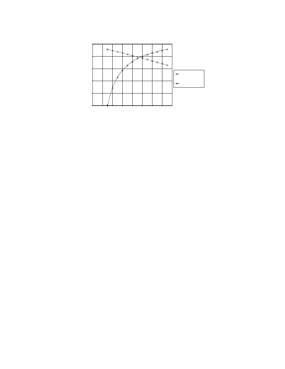
In
, the reversible work for an electrochemical cell is compared to that of a reversible heat
engine. The electrochemical cell in this example is a fuel cell that uses hydrogen, H
2
, and oxygen, O
2
, to
produce water vapor, H
2
O. As the temperature increases, the change in the Gibbs energy of the reaction
decreases, so from Eq. (3.35), the maximum work output from the fuel cell also decreases. In this case,
the Gibbs energy of the formation of water vapor is –228.582 kJ/mol at standard temperature and pressure
(298.15 K and 1 atm) and decreases to –164.429 kJ/mol at 1500 K. The reversible work of the heat engine,
using the HHV of H
2
as the source of heat, increases with temperature because the Carnot cycle efficiency
increases. Below 950 K, the hydrogen fuel cell converts more of the chemical energy of its reactants (H
2
and O
2
) to work, but above 950 K, the Carnot engine produces more work from the combustion of H
2
.
Thermal efficiency of automobile engines is usually calculated in terms of power, so the heat input is
written as a rate according to the flow rate of fuel. By incorporating the flow rate, the thermal efficiency
includes a factor related to the completeness of the combustion of fuel. For fuel cells, the analogous
concept to completeness of combustion is fuel utilization, a measure of the fuel consumed to produce an
electrical current. In electrical terms, it is called current efficiency,
η
I
, and is given in Eq. (3.39). Its inverse
is the fuel stoichiometry, which is the amount of fuel fed to the cell compared to amount the cell requires
to provide the electrons demanded.
(3.39)
FIGURE 3.9 An electron, e
–
, doing work as it moves through a potential difference, E.
+
E
−
e −
batter
y
η
th,cell
W
cell
HHV
-------------
n
e
FE
HHV
-------------
=
=
η
th,cell,max
n
e
FE°
HHV
--------------
=
η
I
I
n
e
FN
fuel
–
----------------------
1
fuel stoichiometry
-------------------------------------------
=
=
© 2003 by CRC Press LLC
In Eq. (3.39), I is the current in A and N
fuel
is the flow rate of fuel in mol/sec. Assume that hydrogen
is used as fuel and that the current efficiency is 83%. One mole of hydrogen contains two moles of
electrons (n
e
= 2), and a current efficiency of 83% means that 83% of the hydrogen is converted to
electricity. The remaining 17% either leaves the cell without reacting or reacts non-electrochemically
(without contributing its electrons to the cell current). For fuel cells with inlet and outlet flows, the fuel
stoichiometry is greater than one (utilization less than 100%), to provide excess fuel to the sections of
electrode at the end of the flow channel, maintaining a more uniform distribution of performance over
the electrode. The excess fuel that exits the cell may be recycled into the fuel cell (if nonreactive compo-
nents are absent) or may be chemically reacted to produce heat. Fuel cells without an outlet (with a dead
end) may have utilizations of 100% because the fuel that is fed to the cell is completely consumed.
3.2.2 Second Law Efficiency
The Second Law efficiency,
η
2nd
, of an energy conversion device indicates its degree of reversibility,
comparing the actual work against the maximum work potential. For example, the performance of an
actual heat engine would be divided by the work produced by a Carnot cycle engine, as in Eq. (3.40).
(3.40)
The expression could also be written in terms of thermal efficiencies,
η, comparing the actual to the
maximum. For fuel cells, using the thermal efficiency expressions of Eqs. (3.37) and (3.38), the Second
Law efficiency becomes a voltage efficiency.
(3.41)
Equation (3.41) is therefore a comparison of the actual voltage to the maximum voltage, which is 1.23
V for a hydrogen–oxygen cell at 25°C and 1 atm. If the voltage were 0.7 V, the Second Law efficiency
would be
η
2nd
= 0.57, indicating that 43% of the available energy was not converted to work. This exergy
(work potential) is lost, dissipated as heat, because of the inefficiencies or polarizations within the fuel
cell (see Section 3.5.3 for Overpotential).
FIGURE 3.10 The reversible work produced by a H
2
/O
2
fuel cell is greater than that of a Carnot engine at
temperatures below 950 K. At higher temperatures, the Carnot engine is able to convert more of the HHV of H
2
(285.840 kJ/mol) into work. The data for the standard Gibbs energy of formation for water vapor was taken from
Lide (1995, pp. 5–64).
0
50
100
150
200
250
0
200
400
600
800
1000 1200 1400 1600
Temperature [K]
Reversible work [kJ/mol]
Electro-
chemical work
Carnot cycle
work
η
2nd,heat engine
W
act
W
rev
----------
W
act
W
Carnot
----------------
=
=
η
2nd,heat engine
η
act
η
rev
--------
nFE
nFE°
------------
E
E°
-----
=
=
=
© 2003 by CRC Press LLC

3.3 Chemical Reactions
In Sections 3.1 and 3.2, the focus was on the conversion of heat to work; this section addresses the
generation of heat by chemical reactions. The First Law relation in Eq. (3.4) can be used to describe the
energy available in a chemical reaction. Eq. (3.42) is written for a control volume.
(3.42)
where H
R
is the enthalpy of the reactants and H
P
is the enthalpy of the products, and both can be separated
into the lower-case letters representing molar quantities, where N
P
and N
R
represent the amount in moles
(mol) in Eqs. (3.43) and (3.44).
(3.43)
(3.44)
In Eqs. (3.43) and (3.44),
is the molar enthalpy of formation (J/mol) at the standard reference
state of 25
°C and 1 atm, and
is the sensible enthalpy in molar units with
as the enthalpy
defined at the standard reference state (298 K, 1 atm).
The maximum work that can be done by the reaction is the reversible work, taking the form of the
exergy expression in Eq. (3.27), but with the entropy change for the system incorporated into the
parentheses with the enthalpy change.
(3.45)
When both products and reactants are at the same temperature as the surroundings (or the dead state),
T
o
, the terms within the parentheses combine to form a property called the Gibbs energy (or Gibbs function),
defined as G = H – TS. See Eq. (3.55). (The superscript
o
represents the property at the standard reference
state; the subscript
o
denotes the temperature of the surroundings, which is not necessarily 25°C.)
(3.46)
Just as the enthalpy is separated into its formation and sensible components, so also can the Gibbs
energy be separated.
(3.47)
The reversible work can then be evaluated by the Gibbs energy at its initial and final states in Eq. (3.48).
(3.48)
Therefore, the concept of exergy leads to the maximum work as being the difference between the Gibbs
energy of the reactants and the products when both are at the same dead state. The same result is reached
in Section 3.4.4 (Maximum Work) but from a different direction; the derivation starts with the definition
of the Gibbs energy and then relates it to maximum work.
For the case when both reactants and products are at T
o
, and T
o
is at the standard reference conditions
of 25
°C and 1 atm pressure, the sensible components are zero, and the maximum work is the difference
between the Gibbs functions of formation, shown in Eq. (3.49).
(3.49)
Q
W
–
H
P
H
R
–
=
H
P
ΣN
P
h
f
o
h
h
o
–
+
(
)
P
=
H
R
ΣN
R
h
f
o
h
h
o
–
+
(
)
R
=
h
f
o
h
h
o
–
h
o
W
rev
ΣN
R
h
f
o
h
h
o
–
T
o
s
–
+
(
)
R
ΣN
P
h
f
o
h
h
o
–
T
o
s
–
+
(
)
P
–
=
h
f
h
h
o
–
T
o
s
–
+
(
)
T
o
g
o
=
g
o
g
f
o
g
g
o
–
+
=
W
rev
ΣN
R
g
f
o
g
g
o
–
+
(
)
R
ΣN
P
g
f
o
g
g
o
–
+
(
)
P
–
=
W
rev
ΣN
R
g
f,R
o
ΣN
P
g
f,P
o
–
=
© 2003 by CRC Press LLC
3.3.1 Adiabatic Flame Temperature
For heat engines, the two reservoirs that provide the temperature gradients for heat addition and
rejection have been simplified by assuming that they remain at constant temperature throughout the
process. In actuality, the high temperature is generated by a combustion process that involves a chemical
reaction between fuel and oxidant. The maximum efficiency of a heat engine, expressed in Eq. (3.24),
is a function of the temperature of the heat source, T
H
, and the greater the temperature, the higher
the efficiency. To achieve the highest possible temperature, the fuel is burned in an adiabatic combus-
tion chamber (fixed volume) so that the chemical energy in the fuel is lost neither through heat transfer
nor to work. Therefore, it is completely dedicated to raising its own temperature. The First Law
equation for a steady-flow adiabatic reactor is written with the heat and work terms as zero in Eq.
(3.50), and the result in Eq. (3.52) shows that the enthalpy of all the product components, H
P
, will be
equal to the enthalpy of all the reactants, H
R
.
(3.50)
(3.51)
(3.52)
The method for calculating the adiabatic flame temperature begins with having a balanced chemical
equation for a combustion reaction, substituting the known molar enthalpy terms from tabulated ther-
modynamic data into Eq. (3.53), and then selecting an estimated temperature for the products. From
the estimated temperature, the enthalpy values are substituted into the product term
, and using trial-
and-error another temperature is selected until the error is minimized.
(3.53)
(At the high temperatures encountered in adiabatic reactions, the products of the reaction may dissociate,
so to determine more accurately the composition of the products, it is necessary to check for chemical
equilibrium using equilibrium constants found in thermodynamic tables. But because this section
addresses the effect of temperature rise on energy conversion, the topic of dissociation is bypassed.)
Example 1: Adiabatic Flame Temperature of Complete Hydrogen
Oxidation Without Dissociation of the Products
The process of determining the adiabatic flame temperature is demonstrated in this example for the
combustion of hydrogen in 34% excess air (34% more oxygen than required for complete combustion).
The reactants enter in two separate streams at T
o
= 25
°C and P
o
= 1 atm.
The balanced equation for the chemical reaction (complete combustion, no dissociation), is:
H
2
+ 0.67(O
2
+ 3.76N
2
)
→ H
2
O
(v)
+ 0.17O
2
+ 2.52N
2
The H
2
O in the products is in the vapor form, denoted by
(v)
.
The highest flame temperature during combustion is reached if the reactor chamber is adiabatic.
Because there is no loss of energy in the form of heat transfer through the reactor walls, and no loss
in the form of work, all of the enthalpy is conserved and appears in the product gases as heat.
Q
W
–
∆H
0
=
=
∆H
ΣH
P
ΣH
R
–
0
=
=
ΣH
P
ΣH
R
=
h
P
ΣN
P
h
f
o
h
h
o
–
+
(
)
P
ΣN
R
h
f
o
h
h
o
–
+
(
)
R
=
products
oxidant
fuel
© 2003 by CRC Press LLC

From Eq. (3.53),
(1 mol H
2
O)[(–241,820 +
– 9904)]
+ (0.17 mol O
2
)[(0 +
– 8682)]
+ (2.52 mol N
2
)[(0 +
– 8669)]
= (1 mol H
2
)[(0 + 0 – 0)]
+ (0.67 mol O
2
)[(0 + 0 – 0)]
+ (2.52 mol N
2
)[(0 + 0 – 0)]
+ 0.17
+ 2.51
= 251,724 + 1475.94 + 21,845.88 = 275,045.82 kJ/kmol
Guess and check
Guess and check
At 2100 K
87,735 + 0.17(71,668) + 2.52(68,417) = 272,329.4 kJ/kmol H
2
At 2150 K
90,330 + 0.17(73,573) + 2.52(70,226) = 279,806.9 kJ/kmol H
2
Interpolate
y = mx + b
279,806.9 – 272,329.4 = 7477.5
275,045.82 – 272,329.4 = 2716.42
2716.42/7477.5 = 0.36328
2100 + 0.36328(2100 – 2150) = 2118.164 K
Interpolating between 2100 and 2150 K, the adiabatic flame temperature is 2118 K or 1845
°C.
Properties from Tables A-18, A-19, A-22, A-23, and A-26 in
Çengel and Boles, 1998
Substance
[kJ/kmol]
[kJ/kmol]
H
2
O
(v)
–241,820
9904
H
2
0
8468
O
2
0
8682
N
2
0
8669
Properties from Tables A-18, A-19, and A-23 in Çengel and Boles, 1998
Substance
at 2100 K
at 2150 K
H
2
O
(g)
87,735
90,330
O
2
71,668
73,573
N
2
68,417
70,226
ΣN
p
h
f
o
h
h
o
–
+
(
)
P
ΣN
R
h
f
o
h
h
o
–
+
(
)
R
=
h
f
o
h
298
o
h
H
2
O
h
O
2
h
N
2
h
H
2
O
h
O
2
h
N
2
h
h
© 2003 by CRC Press LLC

3.3.2 Exergy Loss Caused by a Temperature Rise
Accompanying the temperature rise in an adiabatic reactor is a fall in the work potential of the fuel. This is
caused by the increase in entropy from reactants to products, which then can be used to calculate the exergy
destroyed using Eq. (3.32). Continuing with Example 1 that determined the adiabatic flame temperature of a
hydrogen oxidation reaction, the next example calculates the exergy destroyed. In the example after that, a
chemical reaction is evaluated for the exergy destroyed when the products are at the same state as the reactants.
Example 2: Exergy Destroyed in Reaching the Adiabatic Flame Temperature
The adiabatic flame temperature of the hydrogen oxidation reaction
H
2
+ 0.67(O
2
+ 3.76N
2
)
→ H
2
O
(v)
+ 0.17O
2
+ 2.52N
2
was calculated to be 2118.164 K (Example 1). The reaction occurred at 1 atm absolute pressure. To
determine the entropy change between products and reactants, the absolute entropy values are
obtained from thermodynamic tables. For the product species, the absolute entropies at 2118.164 K
are interpolated between 2100 and 2150 K, with the entropy values from Tables A-18, A-19, and A-23
in Çengel and Boles 1998.
Besides temperature, entropy is also a function of pressure, so for a gas mixture, the tabulated entropy
values are adjusted according to the partial pressure of each species using Eq. (3.54), assuming that
the gases behave as ideal gases.
(3.54)
The term
is the absolute entropy value taken from the tables, R
u
is the (universal) molar gas constant,
y
i
is the mole fraction of the species in the gas mixture, P
m
is the total pressure of the gas mixture, and
P
o
is the reference pressure (1 atm).
The entropy of reactants and products can be calculated in a spreadsheet for each of the species. N
i
is
the number of kilomoles and y
i
is the mole fraction. The H
2
fuel enters by a separate stream from the
air, so y
H2
= 1 and y
O2
= 0.21. The products exit the reactor from one outlet.
Tabulated entropy values for interpolation
Temperature [K]
Gas
2100
2118.164
2150
H
2
O
(g)
267.081
267.5242
268.301
O
2
270.504
270.8291
271.399
N
2
253.726
254.0355
254.578
Reactant
N
i
y
i
s
o
i,298K
–R
u
· ln(y
i
· P
m
)
N
i
· s
i
H
2
1
1
130.574
0
130.574
O
2
0.67
0.21
205.033
12.976
146.066
N
2
2.52
0.79
191.502
1.960
487.524
S
r
764.164
Product
s
o
i,2118.2K
S
sys
= + 212.770
kJ/(kmol
H2
·K)
H
2
O
(v)
1
0.2710
267.524
10.856
278.380
O
2
0.17
0.0461
270.829
25.589
50.391
N
2
2.52
0.6829
254.036
3.171
648.160
S
p
976.931
s
i
T P
i
,
(
)
s
i
o
T
( ) R
u
y
i
P
m
P
o
----------
ln
–
=
s
i
o
}
© 2003 by CRC Press LLC

(The numbers have been rounded in this presentation, but all digits were carried through the calcu-
lation in a spreadsheet.)
So for one mole of hydrogen fuel, the exergy destroyed in the reaction was X
dest
= 63,405 kJ/kmol
H2
;
this amount of work potential was expended to reach a high temperature, but useful work has yet to be
done. Work could be done if heat were transferred from the high-temperature gas to the working fluid
of a heat engine, as in a heat exchanger (combustor), such as that in
. In the heat transfer process,
though, the exergy would be further reduced by a factor of 1 – T
L
/T
H
(see Section 3.1.5).
How much of the total work potential of the reactants was destroyed in the reaction to reach the
adiabatic flame temperature? To determine the exergy of the reactants, the exergy of the products is
determined at the dead state (in this example, 25°C and 1 atm), and the exergy change is the total work
potential of the reactants. Because the temperature of the products is the same as that of the reactants,
the reaction could be considered to have occurred at constant temperature; however, heat has been
generated and then dissipated to the surroundings.
Example 3: Exergy of Reactants at the Dead State, and Fraction
Lost in Reaching the Adiabatic Flame Temperature
At 25°C and 1 atm, the H
2
O in the products appears as a saturated liquid (both liquid and vapor),
and the fraction of vapor is calculated by using the saturation pressure of water at 25°C: P
sat
= 3.169
kPa at 25°C.
Therefore, the balanced chemical equation is:
H
2
+ 0.67(O
2
+ 3.76N
2
)
→ 0.913H
2
O
(l)
+ 0.087H
2
O
(v)
+ 0.17O
2
+ 2.52N
2
The entropy of the products is calculated in the same way as in the previous example, adjusting the
absolute entropy according to the mole fraction, y
i
, of the species. Liquid water is in a separate phase
from the gaseous products, so its y
H2O(l)
= 1.
The entropy of the products is S
p
= 606.172 kJ/(kmol
H2
· K), which is lower than the total entropy of
the reactants, so the change in entropy of the system, S
sys
, is negative.
Product
N
i
y
i
s
o
i,298 K
–R
u
· ln(y
i
· P
m
)
N
i
· s
i
H
2
O
(l)
0.913
1
69.92
0
63.848
H
2
O
(v)
0.087
0.0313
188.83
28.809
18.901
O
2
0.17
0.0612
205.033
23.225
38.804
N
2
2.52
0.9075
191.502
0.807
484.619
S
p
606.172
S
gen
= S
sys
+ S
surr
0
X
dest
T
o
S
gen
298 212.7699
(
)
63,405 kJ/kmol
H2
=
=
=
P
sat
P
tot
⁄
3.169 101.325
⁄
0.03128
=
=
N
vapor
P
sat
P
tot
⁄
(
) N
tot,gas
⋅
0.03128
(
) N
vapor
0.17
2.52
+
+
(
)
⋅
0.08685
=
=
=
S
sys
606.172
764.164
–
=
S
sys
157.993 kJ/ kmol
H2
K
⋅
(
)
–
=
© 2003 by CRC Press LLC

But the entropy generated in the reaction has increased because of the heat generated from the reaction
and transferred to the surroundings, Q
out
. The First Law equation (Eq. 3.42) and entropy equation
(Eq. 3.16) are used to determine S
gen
.
The exergy destroyed in the reaction is calculated by multiplying the temperature of the dead state
and the entropy generated in the reaction, as in Eq. (3.32):
The exergy destroyed in oxidizing the hydrogen fuel and in bringing the products to the dead state is
the exergy of the reactants. (It may be called the chemical exergy of fuel, but in this example, the
quantity of reactants is greater than the stoichiometric amount required, so the result may be different
than that found in chemical exergy tables.)
Referring back to Example 2 (Exergy Destroyed in Reaching the Adiabatic Flame Temperature), the
exergy destroyed in reaching the adiabatic flame temperature was X
dest
= 63,405 kJ/(kmol
H2
· K).
Because the exergy of the reactants was 234,926 kJ/(kmol
H2
· K), the fraction of exergy lost in raising
the temperature of the products of the reaction was
Therefore, before the exergy of the reactants could be used to produce useful work in a heat engine,
27% of it was expended in raising the temperature of the products. A more efficient use of the exergy
would bypass the first step of raising the temperature, converting the exergy directly to work in an
isothermal reaction. In this example, the exergy was converted to heat, which was transferred to the
surroundings; instead of being converted to heat, the exergy could have been converted to electrical
work by an electrochemical device, namely, a fuel cell. If the work potential of the fuel were converted
to electrical work, based on Eq. (3.46), the maximum voltage would be E° = W/(n · F) = 234,926/
(2 · 96,485) = 1.217 V instead of 1.229 V because of the excess air in the reactants and the water vapor
FIGURE 3.11 The heat addition process into a combustor is divided into two stages: adiabatic combustion (left)
and heat transfer (right).
fuel
oxidant
W
net
T
o
Q
out
H
P
H
R
–
0.913
(
) 285,830
–
(
)
0.087
(
) 241,820
–
(
)
+
[
]
P
0
[ ]
R
–
=
=
282,008
kJ/kmol
H2
–
=
S
surr
Q
out
–
T
o
⁄
282,008
–
(
) 298
⁄
–
=
=
+946.335
kJ/ kmol
H2
K
⋅
(
)
=
S
gen
S
sys
S
surr
+
–157.993
946.335
+
=
=
+788.342
kJ/ kmol
H2
K
⋅
(
)
=
X
dest
T
o
S
gen
298
(
) 788.342
(
)
=
=
234,926
kJ/kmol
H2
=
Fraction of exergy lost
63,405 234,926 kJ/kmol
H2
⁄
=
0.270
=
© 2003 by CRC Press LLC

in the products, both leading to a deficiency in the maximum work, which is expressed in Eq. (3.49):
W
rev
=
∆G
f
= 237,180 kJ/kmol
H2
for liquid water at 25°C and 1 atm.
In summary, because the heat engine requires a high-temperature reservoir as a source of heat, 27%
of the work potential of the fuel is consumed in reaching the adiabatic flame temperature, even before
useful work can be done. A further loss in exergy occurs as the heat engine converts the heat into
work, achieving the Carnot cycle efficiency as a maximum limit. Fuel cells, however, convert exergy
to work directly, bypassing the act of raising the temperature of the gas. This is the advantage of fuel
cells: the exergy of fuel is directed more to doing useful work than to reaching high temperatures, as
in heat engines.
3.4 Chemical Thermodynamics
Chemical reactions proceed in the direction that minimizes the Gibbs energy. The change in Gibbs
energy is negative as the reaction approaches equilibrium, and at chemical equilibrium the change in
Gibbs energy is zero. The maximum work that an electrochemical cell can perform is equal to the
change in the Gibbs energy as the reactants go to products. This work is done by the movement of
electrical charge through a voltage, and at equilibrium the voltage is related to the change in Gibbs
energy as shown earlier in Eq. (3.35). The Nernst equation is based on the Gibbs energy change and
is derived in this section.
The basis for the equations in this section is the definition of Gibbs energy.
(3.55)
In the differential form, the Gibbs energy becomes
Substituting the definition of enthalpy for H gives
The first term, dU, is replaced by the First Law of Thermodynamics (based on Eq. 3.1) to give the
general expression for the change in Gibbs energy as applied to a closed (properties constant with time;
∆E = 0), stationary system:
(3.56)
3.4.1 Criterion for a Spontaneous Reaction
The direction of spontaneous reactions is governed by the Second Law of Thermodynamics, which states
that the entropy generated must be greater than or equal to zero. For a reaction at constant temperature
and pressure in a closed system, the expression in Eq. (3.56) becomes
If the system is restricted to doing only expansion-type work,
δW cancels with PdV to give Eq. (3.57).
(3.57)
The Second Law of Eq. (3.6) is rewritten with an inequality sign (= for a reversible and
≥ for an
irreversible process), and it is substituted into Eq. (3.57) to give Eq. (3.58).
G
H
TS
–
=
dG
dH
TdS
–
SdT
–
=
dG
d U
PV
+
(
) TdS
–
SdT
–
=
dG
dU
PdV
VdP
TdS
–
SdT
–
+
+
=
dG
δQ δW
–
PdV
VdP
TdS
–
SdT
–
+
+
=
dG
δQ δW
–
PdV
TdS
–
+
=
dG
δQ TdS
–
=
© 2003 by CRC Press LLC

(3.58)
With the Second Law, Eq. (3.57) becomes
Therefore, in Eq. (3.59), to satisfy the Second Law, a reaction at constant temperature and pressure
(
T,P
) will proceed in a direction of a negative change in Gibbs energy to the point where it reaches a
minimum, dG = 0. When dG = 0, the reaction is at equilibrium.
(3.59)
If the change is positive, the reaction violates the Second Law of Thermodynamics.
3.4.2 The Effect of Temperature and Pressure on
∆G
The Gibbs energy is a function of temperature and pressure, and the effects of T and P on
∆G are shown
in the following derivation based on Eq. (3.56). For a reversible process,
δQ and TdS in Eq. (3.56) cancel
because of the Second Law relationship. If the system is restricted to doing only expansion work, then
δW and PdV cancel:
(3.60)
For an ideal gas, if T is constant, the Gibbs energy at one pressure can be determined with respect to
its value at a reference pressure. The ideal gas equation of state begins the derivation for an expression
that shows the pressure dependency of the Gibbs function:
In the ideal gas equation, n is the number of moles, R is the molar gas constant, and T is the absolute
temperature.
For an isothermal process, Eq. (3.60) becomes:
The ideal gas equation is substituted for V,
and the differential is integrated.
The Gibbs energy change for a change in pressure at constant temperature is
dS
δQ
T
-------
rev,irrev
≥
δQ TdS
–
0
≤
dG
δQ TdS
–
=
0
≤
dG
(
)
T P
,
0
≤
dG
VdP
SdT
–
=
PV
nRT
=
dG
VdP
=
dG
nRT
dP
P
------
=
dG
1
2
∫
nRT
dP
P
------
1
2
∫
=
G
2
G
1
–
nRT
P
2
P
1
-----
ln
=
© 2003 by CRC Press LLC

If state 1 is replaced by a standard reference state, G
°, and a reference pressure, P°, the change in Gibbs
energy is
(3.61)
Eq. (3.61) can be rewritten in a molar quantity (lowercase) (kJ/mol) and denoted by the overhead bar,
—
:
The standard Gibbs energy at the reference state is a function only of temperature, and the pressure
term allows the Gibbs to be calculated for different pressures. In thermodynamics texts, the standard
Gibbs function is tabulated in terms of temperatures at a fixed reference pressure (P
° = 1 atm).
(3.62)
This equation resembles Eq. (3.54), which was used in Section 3.3.2 (Example 2) to determine the
entropy of the components in a gas mixture.
3.4.3 Equilibrium of a Gas Mixture
For a chemical reaction occurring at constant temperature and pressure, the reactant gases A and B form
products M and N. The stoichiometric coefficients are written with the italicized, lowercase letters a, b,
m, and n.
The change in the Gibbs energy,
∆G, is denoted as the difference between the products and reactants.
Eq. (3.62) is substituted for each of the four terms.
The standard Gibbs energy terms can be consolidated into the change in standard Gibbs energy,
∆G°.
The reference pressure, P
°, is usually taken as 1 atm, and the expression can be simplified to
Substituting Q as the general reaction quotient for the pressures,
G
2
G
o
nRT
P
2
P
o
-----
ln
+
=
g
2
g
o
RT
P
2
P
o
-----
ln
+
=
g
i
T P
i
,
(
)
g
i
o
T
( ) RT
P
i
P
o
-----
ln
+
=
aA
bB
mM
nN
+
+
∆G
mg
M
ng
N
ag
A
–
bg
B
–
+
=
∆G
m g
M
o
RT
P
M
P
o
------
ln
+
n g
N
o
RT
P
N
P
o
------
ln
+
a g
A
o
RT
P
A
P
o
-----
ln
+
–
b g
B
o
RT
P
B
P
o
-----
ln
+
–
+
=
∆G
o
mg
M
o
ng
N
o
ag
A
o
–
bg
B
o
–
+
=
∆G
∆G
o
RT
P
M
m
P
N
n
P
A
a
P
B
b
-------------
ln
+
=
© 2003 by CRC Press LLC

the expression is simplified into Eq. (3.63) for the change in Gibbs energy of a reaction involving gases.
(3.63)
3.4.4 Maximum Work
The maximum work that a system can perform is related to the change in Gibbs energy. Taking the
general expression in Eq. (3.56) and substituting the Second Law for a reversible process, the
δQ cancels
with –TdS:
At constant temperature and pressure, only the work terms remain.
Eq. (3.64) shows that the change in Gibbs energy of a chemical reaction is the non-expansion work
the system can perform.
(3.64)
A type of non-expansion work is electrochemical work, W
e
, in which electrical charge moves through
a voltage.
In the integrated form of Eq. (3.64), the Gibbs energy change is the negative of the electrochemical work.
(3.65)
This expression resembles Eq. (3.48), which was derived in Section 3.3 (Chemical Reactions) and was
based on the concept of exergy. To make the exergy equation identical to Eq. (3.65), the reference dead
state, T
o
, is set to the temperature of the reactants for the reactant term and that of the products for the
product term.
3.4.5 The Nernst Equation and Open Circuit
The general expression in Eq. (3.63), which was derived for gas mixtures, can be converted to an
expression for electrochemical equilibrium by using the work relationship presented earlier in Eq. (3.36).
(3.66)
where W
e
is the electrochemical work, n
e
is the number of electrical charges (electrons or protons)
transferred in the reaction, F is the charge carried by a mole of electrons (or protons), and E is the voltage
difference across the electrodes.
The change in Gibbs energy is equal to the negative of the electrochemical work as shown in Eq. (3.65).
Substituting Eq. (3.66) into Eq. (3.65) gives Eq. (3.67).
(3.67)
Q
P
M
m
P
N
n
P
A
a
P
B
b
-------------
=
∆G
∆G
o
RT
Q
ln
+
=
dG
δW
–
PdV
VdP
SdT
–
+
+
=
dG
δW
–
PdV
+
=
dG
δW PdV
–
(
)
–
=
dG
δW
e
–
=
∆G
δW
e
=
W
e
n
e
FE
=
∆G
n
e
FE
–
=
© 2003 by CRC Press LLC

The same substitution is applied to the standard Gibbs energy to define the standard potential, E
°, in
Eq. (3.68).
(3.68)
Equation (3.63), shown below, is rewritten in terms of voltages after the substitutions of Eq. (3.67)
and Eq. (3.68).
(3.63)
The change in Gibbs energy is equal to the standard electrode potential, E
°, minus a term that is
dependent on the partial pressures of the reaction gases, Q, and Eq. (3.69) is called the Nernst equation.
(3.69)
For example, for a hydrogen–oxygen fuel cell, the overall reaction stoichiometry is
H
2
+ 1/2O
2
→ H
2
O
Two electrons are transferred in this reaction, so n
e
= 2. And the partial pressures of water, hydrogen,
and oxygen are included in the reaction quotient.
If the denominator of the reaction quotient is less than the numerator, the natural log term subtracts
from the standard electrode potential, lowering the performance of the fuel cell. Therefore, diluting the
reactant gases will lower the maximum voltage that the cell can produce. For instance, when a fuel cell
operates on products of a fuel reforming reaction, the hydrogen may be diluted with carbon dioxide and
nitrogen. Likewise, if air is used as the reactant, then the mole fraction of oxygen is 0.21.
3.5 Electrochemical Kinetics
In electrochemistry, a chemical reaction involves both a transfer of electrical charge and a change in
Gibbs energy. The electrochemical reaction occurs at the interface between an electrode and a solution
(or electrolyte). In moving from an electrolyte to an electrode, the charge must overcome an activation
energy barrier, and the height of the barrier determines the rate of the reaction. The Butler–Volmer
equation, which applies to fuel cells, is derived based on the Transition State Theory (also called Absolute
Rate Theory).
3.5.1 Electrode Kinetics
The general half-reaction expression for the oxidation of a reactant is:
Red
→ Ox + ne
–
where reactant “Red” loses electrons and becomes “Ox,” the product of oxidation, and n is the number
of electrons that are transferred in the reaction.
∆G
o
n
e
FE
o
–
=
∆G
∆G
o
RT
Q
ln
+
=
E
∆G
o
n
e
F
----------
RT
n
e
F
--------
Q
ln
–
=
E
E
o
RT
n
e
F
--------
Q
ln
–
=
E
E
o
RT
2F
-------
P
H
2
O
P
H
2
P
O
2
1 2
⁄
------------------
ln
–
=
© 2003 by CRC Press LLC

For the opposite direction, “Ox“ gains electrons, undergoing reduction to form “Red” in the half-
reaction
Ox + ne
–
→ Red
The tabulated standard reduction potentials reflect the potential produced in going in this direction,
most likely because it is the direction for spontaneous chemical reactions.
On an electrode at equilibrium conditions, both processes occur at equal rates and the currents
produced by the two reactions balance each other, giving no net current from the electrode
Ox + ne
–
Red
(3.70)
3.5.2 Single-Step Electrode Reactions
Both oxidation and reduction reactions occur on an electrode even if one direction is dominant. At
equilibrium, when both rates are equal, electrons are produced and consumed at the same rate, so the
net current is zero. When considering only one direction of the reaction, the current that is produced is:
I = nA · F · j
where I is the current with units of amperes [A], A is the active area of the electrode [cm
2
], F is Faraday’s
constant (the charge, Coulombs [C], per mole of electrons = 96,485 C/mol e
–
), and j is the flux of reactant
reaching the surface [mol/sec].
A more general form of the same equation eliminates the area from the equation, allowing for a more
direct comparison of the current density produced by different electrodes:
i = nF · j
(3.71)
The current is produced from the reactants that reach the surface of the electrode and lose or gain
electrons. The flux, therefore, is determined by the rate of the conversion of the surface concentration
of the reactant. For the forward (subscript
f
) reaction (
→) of Eq. (3.70), the flux arising from the reduction
of “Ox” is:
j
f
= k
f
[Ox]
o
(3.72)
The subscript
o
beside the brackets refers to the surface concentration of the reactant, and k
f
is the
forward rate coefficient.
In the backward direction (subscript
b
;
←) of Eq. (3.70), the flux produced by the oxidation of “Red” is:
j
b
= k
b
[Red]
o
(3.73)
and the backward rate coefficient is k
b
.
The net flux is the difference between the two competing reactions:
j = j
f
– j
b
(3.74)
Substituting Eqs. (3.72) and (3.73) into (3.74) and Eq. (3.74) into (3.71), the net current density that
appears on the electrode when a current is produced is shown in Eq. (3.75).
i = n (Fk
f
[Ox]
o
– Fk
b
[Red]
o
)
(3.75)
3.5.3 The Butler–Volmer Equation
The heterogeneous rate coefficient, k, in Eq. (3.76) is a function of the Gibbs energy of activation, and
its expression is derived from the Transition State theory (see Atkins, 1998, Chapter 27).
© 2003 by CRC Press LLC

(3.76)
Because an electrochemical reaction occurs in the presence of an electric field, the Gibbs energy of
activation in Eqs. (3.77) and (3.78) includes both chemical and electrical terms:
reduction
(3.77)
oxidation
(3.78)
The subscript
c
is the chemical component. The electrical component contains
∆φ, which is the change
in potential. The plus sign in front of the electrical component applies to the reduction reaction and the
minus reflects an oxidation reaction.
β is called the transfer coefficient (and sometimes it is represented
as
α). In theory, it varies between zero and one, depending on the symmetry of the transition state in
the electrochemical reaction. Experimentally, it has been determined to be about 0.5.
For a reduction reaction, Eq. (3.77) is substituted into Eq. (3.76):
(3.79)
The exponential term in Eq. (3.79) is separated into chemical and electrical components in Eq. (3.80):
(3.80)
The overpotential,
η, is defined in Eq. (3.81) as the actual potential, ∆φ, minus the reversible potential,
∆φ
rev
:
(3.81)
For a hydrogen–oxygen fuel cell, the reversible potential of the anode, where hydrogen oxidation
occurs, is 0 V. For the oxygen reduction reaction at the cathode, the reversible potential is +1.23 V at
25°C. In an operating fuel cell, the overpotential of the anode is positive, which means the electrode
potential is higher than 0 V; for the cathode, the electrode potential is below +1.23 V, which means the
overpotential is negative. The discussion following Eq. (3.84) explains the relationship between overpo-
tential and current.
Substituting the overpotential for the electrical term of Eq. (3.80), the reduction and oxidation rate
expressions are
reduction
oxidation
All of the terms except for the rightmost exponent can be consolidated into a constant, k
o
, for both
of the directions:
k
k
B
T
h
---------
∆G
≠
–
RT
-------------
exp
=
∆G
≠
∆G
c
≠
nF
∆φ
+
=
∆G
≠
∆G
c
≠
n 1
β
–
(
)F∆φ
–
=
k
f
k
B
T
h
---------
∆G
c,f
≠
n
βF∆φ
+
[
]
–
RT
--------------------------------------------
exp
=
k
f
k
B
T
h
---------
∆G
c,f
≠
–
RT
---------------
n
βF∆φ
–
RT
---------------------
exp
exp
=
η
∆φ ∆φ
rev
–
=
k
f
k
B
T
h
---------
∆G
c,f
≠
–
RT
---------------
n
βF∆φ
rev
–
RT
-------------------------
n
βFη
–
RT
-----------------
exp
exp
exp
=
k
b
k
B
T
h
---------
∆G
c,b
≠
–
RT
---------------
n 1
β
–
[
]F∆φ
rev
RT
------------------------------------
n 1
β
–
[
]Fη
RT
---------------------------
exp
exp
exp
=
k
f
k
o,f
βFη
–
n
βFη
–
-----------------
exp
=
reduction
© 2003 by CRC Press LLC

Therefore, substituting into Eq. (3.75), the current density is
(3.82)
When the electrode is in equilibrium and at its reversible potential, the overpotential and external
current are both zero. In this condition, the exchange current density, i
o
, is defined in Eq. (3.83) as the
current flowing equally in both directions.
nF[Ox]
o
k
o,f
= nF[Red]
o
k
o,b
≡ i
o
[A/cm
2
]
(3.83)
The exchange current density incorporates the kinetic term that includes the chemical portion of the
electrochemical Gibbs energy of activation. Because of this, it can be used as a comparison between
different catalysts: the smaller the activation energy, the larger the exchange current density — and the
better the catalyst.
After substituting the exchange current density into Eq. (3.82), the final form for the current density
is Eq. (3.84) and is called the Butler–Volmer equation.
(3.84)
Equation (3.84) is a general description of an electrochemical reaction, containing both reduction (left
term) and oxidation (right term) components. If the overpotential,
η, of the electrode is positive, meaning
that the actual potential is higher than the reversible potential (Eq. 3.81), then the oxidation component
becomes large. At the same time, the reduction reaction (left term) on the electrode becomes small —
and does so quickly because of the exponential function. Together, the net current density is negative,
which corresponds to a net oxidation reaction where electrons leave the electrode, as at the anode of a
fuel cell. Considering a negative overpotential in which the actual potential is lower than the reversible
potential, it is the left-hand, reduction reaction exponential term in Eq. (3.84) that dominates. In an
operating fuel cell, this is the condition of the cathode electrode, where the reduction of oxygen takes place.
In operating fuel cells, because the cathode reaction of oxygen reduction requires a more significant
overpotential than the anode reaction, the performance for the entire fuel cell may be described by only
one of the exponential terms in Eq. (3.84). Using only one term also allows the equation to be rearranged,
solving for the overpotential at a given current density. An example of this equation will be given in
Chapter 4, which discusses the effects that different processes have on the overall fuel cell performance.
3.6 Conclusions
Using the concept of exergy from engineering thermodynamics, the first section of this chapter showed
that an isothermal energy conversion process is less irreversible than a combustion process intended for
reaching high temperatures. A fuel cell extracts the chemical energy of reactants electrochemically,
converting it directly to electricity rather than the intermediate form of heat, as is done in the combustion
process for a heat engine. In the examples of hydrogen oxidation, the high-temperature combustion
reaction consumes 27% of the exergy in the reactants, even before useful work is produced by a heat
engine, and the exergy is reduced further in the heat engine, achieving, at best, the Carnot cycle efficiency.
For a fuel cell, because of its isothermal electrochemical reaction, more of the chemical energy is converted
into useful work.
k
b
k
o,b
n
n1
β
–
[
]Fη
RT
---------------------------
exp
=
oxidation
i
nF Ox
[
]
o
k
o,f
n
βFη
–
RT
-----------------
exp
nF Red
[
]
o
k
o,b
n 1
β
–
[
]Fη
RT
---------------------------
exp
–
=
i
i
o
n
βFη
–
RT
-----------------
exp
n 1
β
–
[
]Fη
RT
---------------------------
exp
–
=
© 2003 by CRC Press LLC

Section 3.4 shows that the maximum work that could be done by an electrochemical device is equal
to
∆G, the difference in the Gibbs energy from reactants to products. This relationship allows equations
based on chemical equilibrium to be written with electrical terms, such as the Nernst equation.
When a fuel cell produces maximum work, the reactions at the electrodes are in equilibrium, and
the net current is zero. When a fuel cell produces power, the electrodes are polarized, having moved
away from equilibrium to produce a net current, as shown in Section 3.5. According to the But-
ler–Volmer equation, the overpotential at the electrodes determines the amount of current. This
activation polarization is dependent on the reaction rate and is therefore determined by the activity
of the electrocatalyst.
Notation for Section 3.1 (Engineering Thermodynamics)
Greek
Subscripts
d
Exact differential
Molar enthalpy
[kJ/kmol]
Molar Gibbs function (or energy)
[kJ/kmol]
Molar entropy
[kJ/kmol/K]
E
Total energy
[kJ/kmol]
H
Enthalpy
[kJ/kmol]
I
Irreversibity
[kJ/kmol]
KE
Kinetic energy
[kJ/kmol]
N
Number of moles
P
Pressure
[Pa]
PE
Potential energy
[kJ/kmol]
Q
Heat energy
[kJ/kmol]
S
Entropy
[kJ/K]
T
Absolute temperature
[K]
T
o
Constant temperature
[K]
U
Internal energy
[kJ/kmol]
V
Volume
[m
3
]
W
Work energy
[kJ/kmol]
X
Exergy
[kJ/kmol]
δ
Inexact differential
η
th
Thermal efficiency
η
2nd
Second Law efficiency
∆
Products minus reactants
1, 2, 3, 4
States 1, 2, 3, 4
adiabatic
Adiabatic (entropy)
Carnot
Carnot cycle
f
Formation (enthalpy, Gibbs function)
gen
Generated (entropy)
H
High (temperature)
in
Input (heat)
L
Low temperature
net
Net (work)
out
Output (heat)
P
Products
R
Reactants
rev
Reversible (heat, work)
h
g
s
© 2003 by CRC Press LLC

Superscript
Notation for Section 3.4 (Chemical Thermodynamics)
Greek
Subscripts
Superscripts
surr
Surroundings (entropy)
sys
System (entropy)
th
Thermal (efficiency)
total
Total (entropy)
o
Standard reference state (25
°C and 1 atm)
d Exact
differential
E
Voltage difference across the electrodes, E
° standard
potential
[V]
F
Faraday’s constant, charge carried by a mole of
electrons (96,485 C/mol)
G
Gibbs energy
[kJ/kmol]
H
Enthalpy
[kJ/kmol]
K
P,eq
Reaction quotient at equilibrium conditions
n
Number of moles
n
e
Number of electrical charges
P
Pressure [Pa]
P
°
Standard reference pressure (1 atm)
Q
General reaction quotient
Q
Heat energy
[kJ/kmol]
R
Molar gas constant (8.3145 kJ/mol/K)
S
Entropy
[kJ/K]
T
Absolute temperature
[K]
U
Internal energy
[kJ/kmol]
V
Volume
[m
3
]
W
Work energy
[kJ/kmol]
W
e
Electrochemical work, W
e,max
maximum
electrochemical work
[kJ/mol]
δ
Inexact differential
∆
Products minus reactants
∂
Partial derivative
1, 2
States 1, 2
T,P
Constant temperature and pressure
rev, irrev
Reversible and irreversible process
A, B, M, N
Reactant gases
i
Component I
o
Standard reference state (Gibbs energy)
a, b, m, n
Stoichiometric coefficients
© 2003 by CRC Press LLC

Notation for Section 3.5 (Electrochemical Kinetics)
Greek
Subscripts
References
Atkins, P.W., Physical Chemistry, 6
th
ed., Oxford University Press, Oxford, 1998.
Çengel, Y.A. and Boles, M.A., Thermodynamics: An Engineering Approach, 3
rd
ed., WCB/McGraw-Hill,
Boston, 1998.
Chen, E.L. and Chen, P.I., Integration of fuel cell technology into engineering thermodynamic textbooks,
in Proceedings of the AMSE 2001 IMECE, Vol. 3, (CD-ROM), New York, Nov. 11–16, 2001, New
York: ASME, paper AES-23647.
Lide, D.R., Ed., CRC Handbook of Chemistry and Physics, 76
th
ed., CRC Press, Boca Raton, FL, 1995, pp.
5-63–5-69.
Further Reading
Barclay, F.J., Combined Power and Process: An Exergy Approach, 2
nd
ed., Professional Engineering, London,
1998.
Breiter, M.W., Electrochemical Processes in Fuel Cells, Springer-Verlag, Heidelberg, 1969.
Hamann, C.H. Hamnett, A., and Vielstich, W., Electrochemistry, Wiley-VCH, New York, 1998.
Gibbs energy of activation,
Gibbs chemical
energy of activation,
Gibbs chemical energy
of activation
[kJ/mol]
[ ]
Concentration, [ ]
o
surface concentration
[Molarity] or [mol/cm
3
]
A
Active area of the electrode
[cm
2
]
e
–
Electron
F
Faraday’s constant (96,485 C/mol)
h
Planck’s constant (6.6261
× 10
–34
J · s)
H
+
Proton
i
Current density
[A/cm
2
]
I
Current [A]
i
o
Exchange current density
[A/cm
2
]
j
Flux of reactant reaching the surface
[mol/sec]
k
Rate coefficient, k
o
in derivation of the Butler–Volmer
equation, k
f
forward rate coefficient, k
b
backward rate
coefficient
[1/s]
k
B
Boltzmann’s constant
n
Number of moles
Ox
Species that is the product of an oxidation reaction
R
Molar gas constant (8.3145 kJ/mol/K)
Red
Species that is the product of a reduction reaction
T
Absolute temperature
[K]
W
e
Electrical
work
[kJ]
β
Transfer coefficient
φ
Potential
[V]
η
Overpotential (or polarization)
[V] or [mV]
b
Backward (rate coefficient, flux)
c
Chemical (Gibbs energy)
f
Forward (rate coefficient, flux)
rev Reversible
(potential)
∆G
≠
∆G
c
≠
∆G
chem
≠
© 2003 by CRC Press LLC
Document Outline
- FUEL CELL TECHNOLOGY HANDBOOK
Wyszukiwarka
Podobne podstrony:
ch03
CH03
CH03 2
BW ch03
ch03
Genomes3e ppt ch03
ch03
Ch03 Instruction List
CP5 39ed Ch03 5
0877 Ch07
fmp dvmc ch03 [b t]
0877 Ch05
DKE285 ch03
Ch03 17
0877 Ch11
0877 Ch09
1287 ch03
więcej podobnych podstron