
7
Prospects of the Direct
Methanol Fuel Cell
7.1
Operating Principle of the DMFC
7.2
Technological Challenges Prior
to DMFC Commercialization
...........................................7-2
Kinetic Limitations
• Electrode Kinetics of the Anode Reaction
7.3
Half-Cell Data
• Single-Cell Data
7.4
Conclusions and Future Recommendations
The direct methanol fuel cell (DMFC) is often considered to be the ideal fuel cell system since it operates on a
liquid fuel, which for transportation applications can potentially be distributed through the current petroleum
distribution network. In addition, the DMFC power system is inherently simpler and more attractive than the
conventional indirect methanol fuel cell, which relies on expensive and bulky catalytic reformer systems to
convert methanol to hydrogen fuel. DMFC systems are potentially cost effective, but only if they can meet the
power requirement necessary for a commercially viable appliance. Unfortunately, commercialization of the
DMFC has been severely impeded by its poor performance compared to H
2
/O
2
systems, amounting to tradi-
tionally no more than one quarter of the power densities, currently achieved with H
2
proton exchange
membrane fuel cells (PEMFCs). The major limitation of the DMFC is the poor performance of the anode,
where more efficient methanol electro-oxidation catalysts are urgently needed. This limitation has prompted a
large research effort to search for efficient methanol oxidation catalyst materials — yet it appears that only
platinum-based materials show reasonable activity and the required stability. The availability of proton
exchange membrane (PEM) materials has extended the operational temperature of DMFCs beyond those
attainable with traditional liquid electrolytes and has led to major improvements in performance over the past
ten years. More recently, the DMFC system has received more attention as the power densities of MEAs have
improved. The performances of DMFCs are now in a range that seems feasible for small portable applications;
as a consequence, this type of application has been identified as a niche market, which the DMFC could
dominate because of reduced system complexity.
This chapter summarizes some of the key considerations with respect to materials and system design
for DMFCs. Overall, DMFC performance is rapidly approaching the level where it will become a com-
mercially viable alternative to H
2
/O
2
systems in certain applications. However, unlike the situation with
the H
2
PEMFC, the DMFC stack and system are still at an early development stage.
7.1 Operating Principle of the DMFC
A schematic of a DMFC employing an acidic solid polymer electrolyte membrane is shown in
Methanol and water electrochemically react (i.e., methanol is electro-oxidized) at the anode to produce
Martin Hogarth
Johnson Matthey Technology Centre
© 2003 by CRC Press LLC
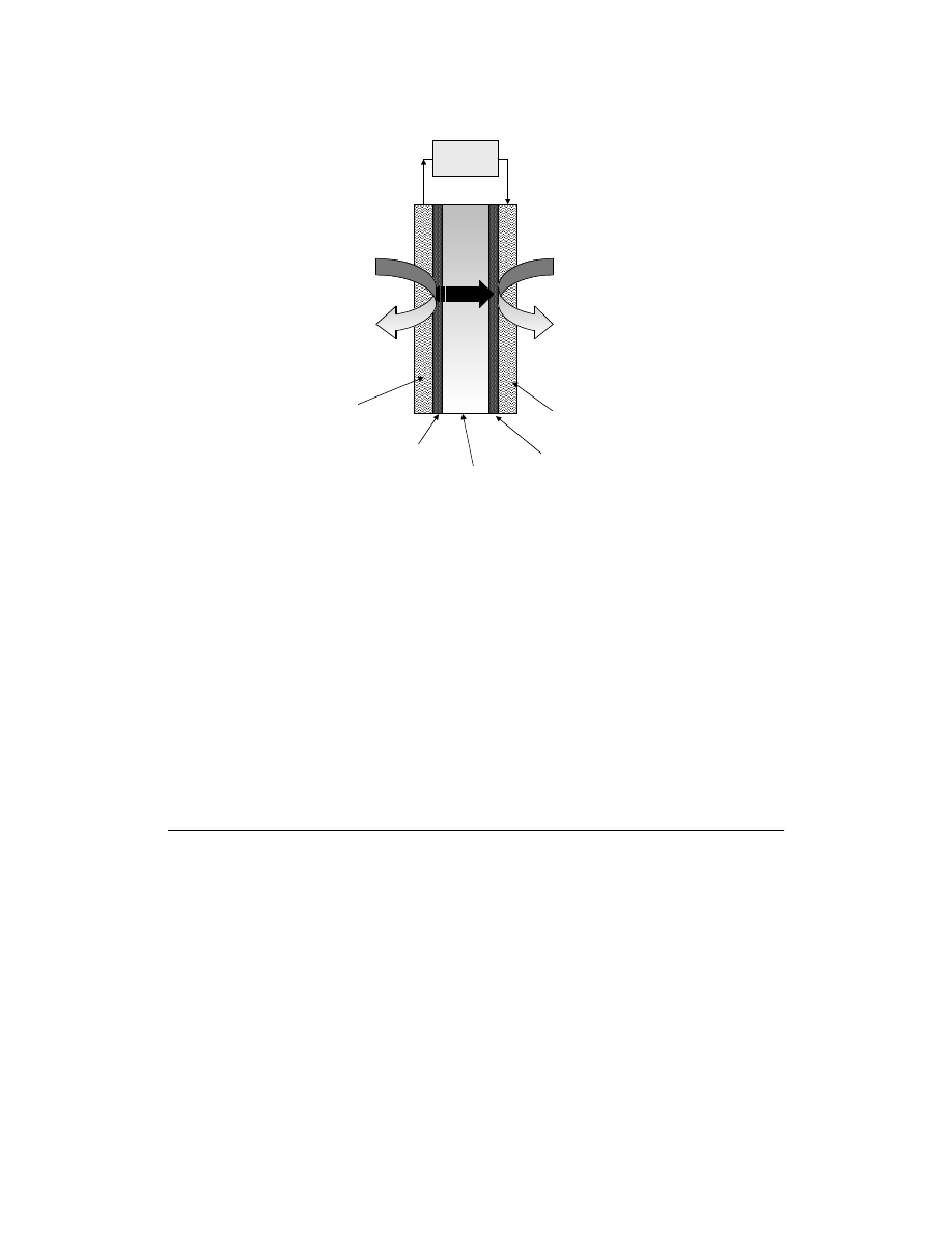
carbon dioxide, protons, and electrons as shown in Eq. (7.1). An acidic electrolyte is advantageous to
aid CO
2
rejection since insoluble carbonates form in alkaline electrolytes (compare the discussion of the
alkaline fuel cell, AFC, in Chapters 1 and 2). The protons produced at the anode migrate through the
polymer electrolyte to the cathode where they react with oxygen (usually from air) to produce water as
shown in Eq. (7.2). The electrons produced at the anode carry the free energy change of the chemical
reaction and travel through the external circuit where they can be made to do useful work, such as
powering an electric motor.
CH
3
OH + H
2
O
→ CO
2
+ 6H
+
+ 6e
–
(
= 0.046 V anode reaction)
(7.1)
3/2O
2
+ 6H
+
+ 6e
–
→ 3H
2
O
(
= 1.23 V cathode reaction)
(7.2)
CH
3
OH + 3/2O
2
+ H
2
O
→ CO
2
+ 3H
2
O (E
cell
= 1.18 V cell voltage)
(7.3)
7.2 Technological Challenges Prior to DMFC Commercialization
Although the DMFC relies on thermodynamically favorable reactions, in practice both the anode and
the cathode electrodes are kinetically limited due to the irreversible nature of the reactions. While this
is also the case for the cathode reaction of the H
2
PEMFC, which is identical to Eq. (7.2), the anode
reaction of the PEMFC is not performance limiting. In the DMFC, however, both anode and cathode
suffer from similarly large overpotentials — as shown in
later in this chapter.
The key performance-limiting factors relating to the anode and cathode electrodes that inhibit com-
mercialization of the DMFC are presented in
and
. In both cases, a kinetic or activation
overpotential effect limits the rate of the electrode reactions, which reduces the cell voltage by up to
400–600 mV at practical current densities. This has a serious impact on the voltage efficiency of the DMFC
(see Chapter 3), which is consequently reduced by up to 50%. Hence, the development of advanced
catalytic systems for methanol oxidation is one area where the efficiency of the DMFC is likely to benefit
most. In practice, the cathode and anode reactions are promoted most effectively by platinum-based
electrocatalysts (see Chapter 6).
FIGURE 7.1 Schematic of a DMFC employing an acidic solid polymer electrolyte membrane.
Oxygen
Water
e-
e-
H
+
H
+
H
+
H
+
Methanol
+ Water
Carbon
dioxide
Driven
Load
Anode
Diffusion
Media
ANODE:
Anode
Catalyst Layer
Acidic
Electrolyte
Cathode Catalyst
Layer
Cathode Diffusion
Media
CATHODE:
E
anode
o
E
cathode
o
© 2003 by CRC Press LLC
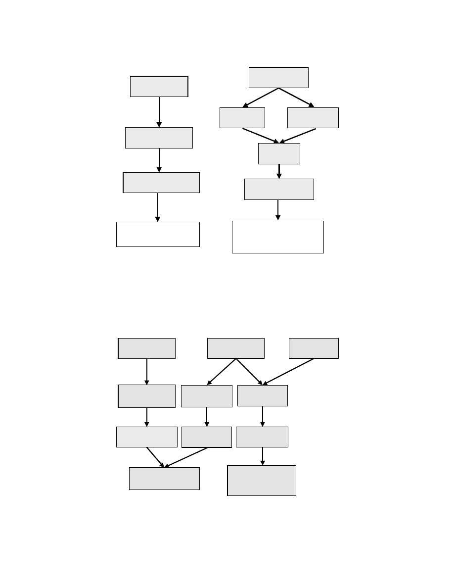
FIGURE 7.2 Technological limitations with the DMFC anode.
FIGURE 7.3 Technological limitations with the DMFC cathode.
Poor Electrode
Kinetics
Large Activation
Overpotential
Mass Transport
CO
2
rejection
Low MeOH
concentration
Electrode
Structure
200-300mV
Cell Voltage Loss
CATALYST
DEVELOPMENT
ELECTRODE
MATERIAL
DEVELOPMENT
25–150mV
Cell Voltage Loss
CATALYST
DEVELOPMENT
ELECTRODE
MATERIAL
DEVELOPMENT
200–300mV
Cell Voltage Loss
>100mV Loss
25–100mV
Loss
Large Activation
Overpotential
Reduced Gas
Permeability
Mixed Cathode
Potential
Poor Electrode
Kinetics
Methanol
Crossover
Mass
Transport
© 2003 by CRC Press LLC

The other major efficiency loss in the electrodes of the DMFC is associated with mass transport effects.
At the anode, these depend on how effectively the liquid fuel can diffuse into the electrode structure and
the resulting product CO
2
gas can be removed from it. These effects can reduce the voltage of the DMFC
by 100 mV or more at practical current densities.
To maximize diffusion, the anode electrocatalyst structure is typically porous in nature and is usually
supported on a porous, electronically conducting diffusion layer, which is typically carbon fiber or carbon
cloth based (see Chapter 4). The design of these layers is particularly important as the DMFC anode is
commonly supplied with only 2 to 4 wt% methanol, diluted with water. This would appear to be a very
low concentration, especially since Eq. (7.1) indicates that stoichiometric quantities of methanol and water
are consumed in the anode reaction. However, such low concentrations are chosen out of necessity to deal
with the high solubility of methanol in most of the currently available electrolyte materials. This high
solubility results in methanol crossover from the anode to the cathode, which not only leads to a reduction
in fuel efficiency but also reduces the efficiency of the cathode by a combination of a mixed potential effect
(25–100 mV, chemical short-circuit) and a mass transport effect (>100 mV, reduced gas permeability).
Similar to the situation at the DMFC anode, mass transport effects are a key performance-limiting
factor at the cathode, and they can result in more than 100 mV cell voltage loss. The design of the cathode
structure is not too dissimilar from that of the anode, but the cathode is designed more to allow effective
diffusion of air to the surface of the catalyst. Like the anode, the cathode structure is designed to effectively
remove the reaction product, in this case water. This can usually be carried out effectively by incorporating
hydrophobic materials, such as PTFE, in the catalyst and diffusion layers. However, any methanol reaching
the cathode from the anode effectively wets the hydrophobic surfaces in the electrode and encourages
water to collect within the structure, reducing access of the air. This effect is not helped by the nature of
the present electrolyte materials, which also allow water to travel quite freely from the anode into the
cathode structure. In practice, DMFCs usually require higher air flows compared to those used in the
H
2
PEMFC to remove excess water, although an appropriate cell design could eliminate this.
To conclude this introduction, therefore, the DMFC’s performance is limited by a number of materials-
related issues, ranging from low-activity catalyst materials to membranes that allow the methanol fuel
to pass freely from the anode to the cathode. In the following sections, attention will be given to a more
detailed review of the anode reaction and the new catalyst materials that have been developed for this
electrode. Until recently, this is where the vast majority of studies have been directed because this is where
the performance of the DMFC is perceived to be most limited.
Other important areas such as membrane research and methanol-tolerant cathode catalysts have received
relatively little attention. As a consequence, the DMFC quite often relies on inheriting technological
advances made in the development of the H
2
PEMFC. This has not always been the best solution to a
problem, particularly in the area of methanol-impermeable membranes. During the last few years,
however, some significant advances in methanol-impermeable membrane development have taken
DMFC technology forward, and this will also be covered later. With respect to new methanol-tolerant
cathode materials, work has also been very limited prior to the last five years.
7.2.1 Kinetic Limitations
Considering only the thermodynamics of the DMFC, in principle methanol should be oxidized spontaneously
when the potential of the anode is above 0.046 V with respect to the reversible hydrogen electrode (RHE)
(see the discussion of electrochemical thermodynamics in Chapter 3). Similarly, oxygen should be reduced
spontaneously when the cathode potential falls below 1.23 V vs. RHE. Hence, the DMFC would produce a
cell voltage of 1.18 V at 100% voltage efficiency, independent of the current demand. In reality, the reactions
shown in Eqs. (7.1) and (7.2) are both highly activated, and hence poor electrode kinetics (kinetic losses)
cause the electrode reactions to deviate from their ideal thermodynamic values in such a way as to bring
about a serious penalty on the operational efficiency of the DMFC. This is demonstrated in
, which
breaks down the various limiting effects, including kinetics, resistance, methanol crossover, and mass trans-
port. Ohmic effects relating to the electrolyte and the electrodes have been discussed in Chapter 4.
© 2003 by CRC Press LLC

In order to draw a current from the DMFC, a far more positive potential (overpotential) is required
at the anode and a more negative potential (overpotential) at the cathode to accelerate the reactions to
a reasonable rate (i.e., to produce a cell current). These are shown in
as the dark gray areas
(kinetic losses), and their effect on the efficiency of the cell is interpreted as a reduction in the light gray
area, which represents the observed voltage from the cell. As Fig. 7.4 demonstrates, the anode and cathode
overpotentials reduce the cell potential by approximately similar amounts. Together, they may be respon-
sible for a loss of DMFC efficiency of approximately 50%.
The poor electrode kinetics at the anode and cathode arise from the fact that the electrochemical
processes are substantially more complex than they appear in Eqs. (7.1) and (7.2). The kinetics of the
oxygen reduction reaction (ORR) are discussed in more detail in Chapters 3, 4 and 6.
A simple argument shows why ORR is a highly activated process: Each O
2
molecule requires the transfer
of four electrons for complete reduction, the simultaneous transfer of these electrons being highly
unlikely. In fact, partial electron transfer takes place leading to the formation of surface intermediates
such as superoxide. The application of a platinum electrocatalyst allows the stabilization of these inter-
mediates and allows the reaction to proceed at a reasonable and useful rate (see Chapter 6). In addition,
the catalyst may accelerate the reaction by opening up new reaction pathways.
In the case of methanol electro-oxidation at the DMFC anode, the picture is less clear. The electro-oxidation
of methanol only occurs at a reasonable rate in the presence of platinum or a platinum-based electrocatalyst.
This reaction has remained an active focus of research, and substantial studies into this process have been
reported in the literature (Parsons and Vandernoot, 1988). However, a great deal of discrepancy exists among
experimental data; this may be due to the wide range of experimental conditions used in the studies.
7.2.2 Electrode Kinetics of the Anode Reaction
The electro-oxidation of methanol to carbon dioxide involves the transfer of six electrons, and it is highly
unlikely that these electrons will transfer simultaneously. It is also unlikely that partial electron transfer
will lead to a range of stable solution intermediates. Clearly, surface-adsorbed species must be present
on the platinum catalyst surface throughout its useful potential range, and these species must be respon-
sible for the poor catalytic activity of platinum towards methanol electro-oxidation.
The postulated mechanisms for methanol electro-oxidation were reviewed comprehensively by Parsons
and Vandernoot (1988) and can be summarized as follows.
Step 1: Electrosorption of methanol onto the catalyst surface to form carbon-containing intermediates
Step 2: Addition of oxygen (from water) to the electrosorbed carbon-containing intermediates to
generate CO
2
FIGURE 7.4 Breakdown of anode-, cathode-, and electrolyte-related performance losses in a DMFC.
1.2
0
Electrode Potential/Cell Voltage (V)
Kinetic Losses
Electrode Ionic/
Ohmic Resistance
Fuel
Crossover
Mass
Transport
Electrolyte
Ionic Resistance
Observed
Cell Voltage
Current (A)
Anode:
~25% Efficiency Loss
Cathode:
~25% Efficiency Loss
Fuel Cell Efficiency ~50%
© 2003 by CRC Press LLC
This corresponds to the following electrochemical reactions:
Pt + H
2
O
→ Pt-OH
ads
+ H
+
+ e
–
(7.4)
Pt-OH
ads
+ Pt-CO
ads
→ 2Pt +CO
2
+ H
+
+ e
–
(7.5)
With respect to the first process (step 1), very few materials are able to electrosorb methanol. In acidic
electrolytes, only platinum-based electrocatalysts have shown the required activity and chemical stability.
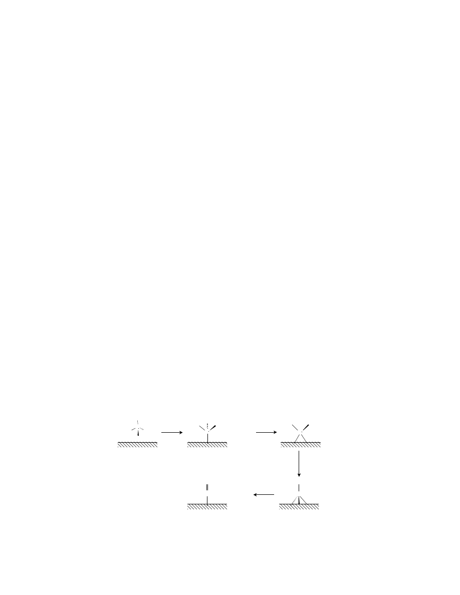
The adsorption mechanism is believed to take place through the sequence of steps shown in
(Kazarinov et al., 1975; Mundy et al., 1990; Christensen et al., 1990). The mechanism shows the elec-
trosorption of methanol on the surface of platinum with sequential proton and electron stripping, leading
to the main catalyst poison, linearly bonded carbon monoxide (Pt-CO). Subsequent reactions are believed
to involve oxygen transfer to the Pt-CO species to produce CO
2
.
The most recent work has been covered by Burstein et al. (1997), Anderson and Grantscharova (1995),
Chrzanowski et al. (1998), Arico et al. (1994), and Liu et al. (1998).
At potentials below about 450 mV, the surface of pure platinum is poisoned by a layer of strongly
bonded CO
ads
. Further electrosorption of methanol cannot take place until the surface-bound CO
ads
is
oxidized to CO
2
, which desorbs from the platinum surface. At potentials below about 450 mV, this process
occurs at an insignificant rate (compare CO poisoning in H
2
PEMFCs — Chapter 6) and hence, the
surface of the pure platinum remains poisoned throughout its useful (low) potential range. This has led
to an intensive search for alternative materials that can electro-oxidize methanol at lower overpotentials,
and in particular materials that might combine with platinum to promote the above processes (Eqs. 7.4
and 7.5). A number of possible explanations may account for the enhanced activities seen for some of
these advanced materials. The most likely are:
1. The binary metal element (e.g., ruthenium) modifies the electronic properties of the catalyst,
weakening the chemical bond between platinum and the surface intermediate (intrinsic effect).
2. The binary element (e.g., ruthenium, tin, lead, or rhodium) is unstable and leaches out of the
alloy to leave a highly reticulated and active surface. This leads to a higher number of extended
step sites, which have been associated with the methanol electrosorption process. In addition,
these low coordination sites may be much more easily electro-oxidized, giving rise to Pt-OH
ads
species at potentials far below that at which planar platinum is oxidized.
3. The binary metal element (e.g., ruthenium, tin, or tungsten) is able to provide an adjacent platinum
site with –OH
ads
through a spillover process (promotion effect). Hence, the catalytic activity is
governed by the potential at which the binary metal elevctro-oxidizes and delivers OH
ads
to adjacent
platinum sites. For materials such as Ru, this occurs at significantly lower potentials (<250 mV)
than is possible on a platinum surface (Gasteiger et al., 1994; Franaszczuk and Sobkowski, 1992;
Hamnett and Kennedy, 1988; Ticanelli et al., 1989). By virtue of this process, at present the most
active methanol electro-oxidation catalysts are based on Pt-Ru alloy materials.
FIGURE 7.5 Methanol electrosorption mechanism in H
2
SO
4
on pure Pt surfaces.
C
OH
H
H
H
Pt
Pt
C
H
H
H
+ H
+
+ e
-
Pt
C
OH
H
Pt
Pt
C
OH
Pt
Pt
Pt
C
O
+ H
+
+ e
-
+ H
+
+ e
-
+ H
+
+ e
-
© 2003 by CRC Press LLC

7.3 Electrode Performance
We will illustrate the effect of using advanced catalytic systems with half-cell and single-cell data.
Half-Cell Data
The development of the DMFC was pioneered in the 1960s and 1970s by Shell and Exxon-Alsthom using
liquid sulfuric acid and alkaline electrolytes, respectively (see Chapter 2). These programs failed to
produce stacks with sufficiently high power densities because of poor electrode kinetics and severe fuel
crossover between the electrodes. In sulfuric acid electrolytes, methanol crossover was a particular
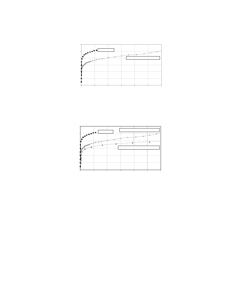
problem since both the anode and cathode catalysts were based on platinum. This is demonstrated in
, which shows the change in performance of an oxygen cathode as a result of methanol crossover.
Clearly, the electrode efficiency is considerably reduced even when low methanol concentrations are used
in the cell.
In recent years, however, significant progress has been made in the development of the DMFC operating
with solid polymer electrolyte materials. These polymer materials have extended the operating temper-
ature of the cell above the boiling point of sulfuric acid and have helped reduce fuel crossover. Electro-
catalyst issues have centered on the need for stable materials with higher intrinsic activities for methanol
electro-oxidation. A number of important half-cell studies have shown progressive improvement in the
anode performance.
A major concern in the development of the current Pt/Ru–based catalyst materials is whether they
can be improved to a level where the DMFC can become a viable alternative to the current H
2
–
PEMFC/
reformer technology. Recent work at the Johnson Matthey Technology Centre has shown that it is
possible to improve Pt/Ru–based catalytic systems further for them to suit DMFC applications.
compares the half-cell electrochemical activities of electrodes fabricated from 20 wt% Pt and 20
wt% Pt/10 wt% Ru catalysts supported on Vulcan XC-72R carbon black, at 80°C in 0.5 M H
2
SO
4
and
2 M methanol. The electrodes consisted of a thin catalyst layer bonded to a Nafion® 117 membrane
and a current-collecting substrate.
One important figure of merit in the determination of catalyst activity, which is rarely considered in the
literature, is the measurement of activity in terms of real metal surface area (mAcm
–2
Pt). This is determined
by the electrosorption of a monolayer of carbon monoxide on the metal surface. This layer is then electro-
chemically oxidized from the surface to produce a charge that can be equated to the total electrochemical
metal area (ECA). This technique allows catalyst activity to be characterized independently of surface area
and clearly distinguishes materials that possess higher intrinsic activity for methanol electro-oxidation. This
is demonstrated in
, which clearly shows that the Pt/Ru materials possess substantially higher activities
than Pt, with the Type II Pt/Ru being significantly more active than the standard Type I Pt/Ru.
FIGURE 7.6 Current/potential curves for an oxygen cathode in the presence of methanol, demonstrating the effects
of methanol crossover.
Effect of Methanol on the Oxygen Reduction
Performance of 20% Pt / XC-72R
0.5M Sulphuric Acid at 80
°C Ambient Oxygen, 1M methanol
Current Density (mA/cm
2
)
E(mV) vs. RHE
Voltage loss
0
100
200
300
400
500
600
700
800
900
1000
0 20 40 60 80 100 120 140 160 180 200
No methanol
1M methanol added
to electrolyte
0.5mg Pt/cm
2
© 2003 by CRC Press LLC
In terms of current densities, the half-cell performance has improved considerably since the 1980s,
from current densities in the range of 20–25 mAcm
–2
at 0.4 V (Cameron et al., 1987) to the present day
state-of-the-art electrodes capable of more than 200 mAcm
–2
at 0.3 V (Hogarth et al., 1995).
Single-Cell Data
A number of engineering criteria are associated with the design and construction of a DMFC. The wide
range of operating temperatures possible with a solid polymer electrolyte system means that methanol
can be supplied as either a liquid or a vapor.
Vapor systems, although offering higher performance and improved mass transport, are more complex
because they require additional hardware to provide cooling.
Liquid-feed systems appear to be simplest from an engineering standpoint. Circulation of the liquid fuel
mixture prevents excessive heating of the cell, reducing the component count and the system size. It is
therefore unsurprising that the majority of research groups have chosen to construct liquid-feed systems.
In the U.S., the Advanced Research Projects Agency (ARPA) regards the DMFC as a potential mobile power
source and also as a possible replacement for some of the primary batteries that are widely used by U.S.
FIGURE 7.7 This graph compares the half-cell electrochemical activities of electrodes fabricated from 20 wt% Pt and
20 wt% Pt/10 wt% Ru catalysts supported on Vulcan XC-72R carbon black, at 80°C in 0.5 M H
2
SO
4
and 2 M methanol.
The electrodes consisted of a thin catalyst layer bonded to a Nafion 117 membrane and a current-collecting substrate.
FIGURE 7.8 This figure clearly shows that the Pt/Ru materials possess substantially higher activities than Pt, with
the Type II Pt/Ru significantly more active than the standard Type I Pt/Ru.
E(mV) vs. RHE
0
0.1
0.2
0.3
0.4
0.5
0.6
Specific Activity (mA/cm
2
Pt)
0
100
200
300
400
500
600
Comparison of 20 wt.% Pt / XC-72R with 20 wt.%
Pt 10 wt.% Ru / XC-72R
0.5M Sulphuric Acid at 80
°C 2M methanol
20 wt.% Pt
20 wt.% Pt 10 wt.% Ru
0
100
200
300
400
500
600
E(mV) vs. RHE
0 0.1 0.2 0.3 0.4 0.5 0.6
Specific Activity (mA/cm
2
Pt)
Comparison of 20 wt.% Pt / XC-72R with Type I
and Type II 20 wt.% Pt 10 wt.% Ru / XC-72R
0.5M Sulphuric Acid at 80
°
C 2M methanol
20 wt.% Pt 10 wt.% Ru (Type II)
20 wt.% Pt 10 wt.% Ru (Type I)
20 wt.% Pt
© 2003 by CRC Press LLC
military forces. With funding from ARPA and the U.S. Department of Energy, several groups have been
collaborating to develop DMFC technologies. These groups include the Jet Propulsion Laboratory (JPL) and
Giner, Inc., Los Alamos National Laboratory (LANL), and International Fuel Cells (IFC, now UTC Fuel Cells).
In Europe, the European Commission has actively funded DMFC projects for the past 10 years under
the JOULE Programmes. Several groups have been active in Europe during this period, the most successful
being Siemens (Germany) and Newcastle University (U.K.). Recently, Johnson Matthey has been collab-
orating with Siemens and Innovision (Denmark) under the framework of JOULE 3 to develop a fuel cell
stack. The successful completion of this project resulted in a 1-kW stack demonstrator.
The above groups have achieved a wide range of cell performances using a variety of electrode compo-
sitions and operating conditions; this makes direct comparison of the data difficult. The minimum goal
required for commercialization of fuel cells operating on methanol and air is judged to be about 250–300
mW
–2
for transportation applications and 30 to 40 mW/cm
2
for near ambient portable applications. For
both applications, these goals would have to be met at a cell voltage of 0.5–0.6 V to attain good efficiency.
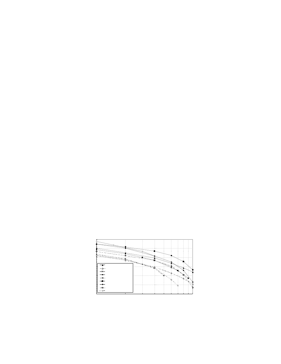
Figure 7.9 compares some of the recent results achieved for single-cell work by the aforementioned
groups. Data plotted with a dashed line correspond to cell operation on air.
Siemens has developed its single cell technology around highly loaded unsupported Pt/Ru black anodes
(4 mgcm
–2
) and Pt black cathodes (4 mgcm
–2
), operating at high temperatures and pressures (Grune
et al., 1994). This company’s best data show a high performance of 0.52 V at 400 mAcm
–2
at 130°C with
pressurized methanol/water vapor and oxygen at 4.4 and 5 bar, respectively. This corresponds to a
respectable power density of about 200 mWcm
–2
, which is approaching the target performance required
for transportation, although this was achieved with oxygen. Durability testing of the single cell shows
that its stability is not sufficient for practical applications.
The Newcastle University group has considered both liquid-feed and vapor-feed systems, with low
loading electrodes containing 2.5 mg Pt cm
–2
(Hogarth et al., 1997a, b; Shukla et al., 1995). A performance
of 0.5 V at 400 mAcm
–2
was achieved at 98°C with oxygen at 5 bar pressure and 2 M methanol/water
vapor. With pressurized air, the performance fell to about 130 mA/cm
2
at 0.5 V, corresponding to a power
density of about 60 mW/cm
2
(Hogarth et al., 1997b). Long-term testing of the membrane electrode
assemblies showed good stability over 18 days.
JPL/Giner, Inc., presented cell data of 0.47 and 0.38 V at a current density of 400 mAcm
–2
for their
liquid-feed DMFC system operating at 90°C with 2.26 atm oxygen and air pressure, respectively (Ren et
al., 1996). They also obtained impressive results for electrodes with low platinum loadings of 0.5 mgcm
–2
,
which are capable of cell voltages near 0.5 V at a current density of 300 mAcm
–2
at 95°C.
Data from LANL (Ren et al., 1995; Surampudi et al., 1994) are very impressive with a best performance
of 0.57 V at 400 mAcm
–2
. This was achieved using Nafion 112 membrane, which is thinner than the
FIGURE 7.9 Comparison of single cell DMFC data from Siemens, Newcastle University, JPL, and LANL. (Data
plotted with a dashed line correspond to cell operation on air.)
Tafel plots of single cell DMFC data
log I/ mAcm
-2
Cell Voltage E(V)
0.1
0.2
0.3
0.4
0.5
0.6
0.7
100
1000
Newcastle oxygen
Newcastle air
Siemens oxygen
JPL oxygen
JPL air
LANL Nafion-112 O2
LANL Nafion-117 O2
LANL Nafion -112 air
LANL Nafion-117 air
© 2003 by CRC Press LLC

favored Nafion 117, with the enhanced performance being a result of the reduced internal cell resistance.
The catalysts consisted of unsupported Pt/RuO
x
at the anode and Pt black at the cathode. LANL uses
high temperatures and pressures to enhance the electrode kinetics and to counter fuel crossover. Fuel
crossover is a severe limitation of the current membrane materials, and it appears that most groups are
relieving this problem by using high gas pressures and flow rates. The performance of the cell in air was
0.52 V at 400 mAcm
–2
at 110°C with anode and cathode pressures of 1.8 and 3 atm, respectively. It is
unclear whether LANL is encountering enhanced fuel crossover with the thinner Nafion 112 membranes
as would be expected. LANL does, however, suggest that the cell performance is limited by the anode
catalyst activity and that the cathode exhibits a degree of methanol tolerance. The performance of the
electrode with Nafion 117 is very similar to the data presented by the Newcastle and JPL groups.
7.4 Conclusions and Future Recommendations
In the last few years, the activity of methanol electro-oxidation catalysts has been improved considerably.
Most improvements have come about through improved operating conditions and through improved
dispersion and control of the composition of existing Pt/Ru materials. In addition, electrode technology
has advanced with the introduction of solid polymer electrolytes such as Nafion, which have extended
the operational temperature and reduced the complexity of modern cells.
The single-cell data presented by various groups demonstrate the influence of parameters such as
temperature, pressure, concentration of reactants, and electrode structure. It appears that the present
level of technology is limited to high temperatures (130°C) and pressures before reasonable performances
can be attained. In this respect, cell performance increases as the temperature and air pressure increase,
so for a given power rating cell size decreases appropriately.
Most groups appear to use a high noble metal loading of up to 4 mgcm
–2
on the anode to increase the
methanol turnover to a useful rate. This level of catalyst loading is prohibitively expensive for traction
applications, and therefore the anode catalyst activity has to be increased by a factor of at least 10 to be able
to reduce the noble metal loading to a more reasonable 0.5 mgcm
–2
. The performance may also be improved
significantly through optimization of the catalyst structure, leading to higher catalyst utilization.
Methanol crossover from the anode to the cathode appears to be a major limitation at present. This
is reflected in the high platinum catalyst loadings and the high gas pressure and flow rates that are
necessary for reasonable cathode performance. The performance of the DMFC would be improved
considerably if a methanol-impermeable electrolyte or methanol-tolerant cathode existed. In the case of
the former, considerable effort has been made to search for alternative membrane materials to minimize
the effects of methanol crossover.
Present electrolyte materials are restricted by poor water management and therefore can only operate
at temperatures below 100°C at ambient pressures. If the operational temperature could increase to 150°C
at ambient pressures, this would considerably enhance the kinetics of the anode reaction. This calls for
new materials that do not require humidification to maintain high conductivity.
Several types of materials have been examined as alternatives to the present perfluorinated sulfonic
acids (Hogarth et al., 2001). Aqueous buffered carbonate electrolytes have been considered since they
offer the primary advantage of low methanol solubility at high temperatures. Others include composite
membranes prepared from tin mordenites and polyacrylic acid, polymolybdenum sulfonic acids, substi-
tuted sulfonic acids, silinols, and hydrogels. Problems exist with these materials, however; they are
chemically unstable, do not possess the required conductivity, or are water soluble.
The alternative to new membrane technology is to employ methanol-tolerant cathode catalysts. High
surface area chevrel phase composites that consist of molybdenum, ruthenium, and sulfur are one
possibility. Although these materials do not offer as yet the same oxygen reduction performance as Pt-
based materials, they are poor methanol electro-oxidation catalysts (Reeve et al., 1998 and 2000; Trapp
et al., 1996).
The DMFC has always been considered the ideal fuel cell. Its key features of simplified system design
and direct use of liquid fuel have in the past been outweighed by the very low power densities achievable.
© 2003 by CRC Press LLC

The poor performance of the cell was due to the poor kinetics of the anode reaction and fuel crossover.
Although the performance levels attained by current developers are not yet sufficient for commercial
application, if the rate of progress made over the past two to three years is maintained, it is likely that
this fuel cell will emerge from the shadows of its hydrogen-fueled counterpart.
References
Anderson, A.B. and Grantscharova, E., J. Phys. Chem., 99, 9149, 1995.
Arico, A.S. et al., Electrochim. Acta, 39, 691, 1994.
Burstein, G.T. et al., Catalysis Today, 38, 425, 1997.
Cameron, D.S. et al., Direct methanol fuel cells: recent developments in search of improved performance,
Platinum Metal Rev., 31, 173, 1987.
Christensen, P.A., Hamnett, A., and Potter, R.J., Ber. Bunsenges. Phys. Chem., 94, 1034, 1990.
Chrzanowski, W. et al., J. New Mater. Electrochem. Syst., 1, 31, 1998.
Franaszczuk, K. and Sobkowski, J., J. Electroanal. Chem., 327, 235, 1992.
Gasteiger, H.A. et al., Electrochim. Acta, 39, 1825, 1994.
Grune, H., Kruft, G. and Waidhas, M., Fuel Cell Seminar, San Diego CA, November 28–December 1,
1994, Abstracts, pp. 474–478.
Hamnett, A. and Kennedy, B.J., Electrochim. Acta, 33, 1613, 1988.
Hogarth, M.P., Christensen, P.A., and Hamnett, A., Proceedings of the First International Symposium on
New Materials for Fuel Cell Systems, Montreal, July 9–13, 1995, p. 320.
Hogarth, M. et al., The design and construction of high-performance direct methanol fuel cells. 1. Liquid-
feed systems, J. Power Sources, 69, 113, 1997a.
Hogarth, M. et al., The design and construction of high-performance direct methanol fuel cells. 2. Vapour-
feed systems, J. Power Sources, 69, 125, 1997b.
Hogarth, M. et al., High temperature membranes for solid polymer fuel cells, ETSU F/02/00189/REP,
U.K. Department of Trade and Industry, 2001.
Kazarinov, V.E., Ttysyachnaya, G.Y., and Andreev, V.N., J. Electroanal. Chem., 65, 391, 1975.
Liu, L. et al., Electrochem. Solid-State Lett., 1, 123, 1998.
Mundy, G.R. et al., J. Electroanal. Chem., 279, 257, 1990.
Parsons, R. and Vandernoot, T., J. Electroanal. Chem., 257, 9, 1988.
Reeve, W. et al., Methanol tolerant oxygen reduction catalysts based on transition metal sulfides, J. Elec-
trochem. Soc., 145, 3463, 1998.
Reeve, R.W. et al., Methanol tolerant oxygen reduction catalysts based on transition metal sulphides and
their application to the study of methanol permeation, Electrochim. Acta, 45, 4237, 2000.
Ren, X., Wilson, M.S., and Gottesfeld, S., Electrochem. Soc. Proc., PV 95–23, Pennington, NJ, 1995.
Ren, X., Wilson, M.S., and Gottesfeld, S., J. Electrochem. Soc., 143, L13, 1996.
Shukla, A.K. et al., A vapour-feed direct methanol fuel cell with proton-exchange membrane electrolyte,
J. Power Sources, 55, 87, 1995.
Surampudi, S. et al., J. Power Sources, 47, 377, 1994.
Ticanelli, E. et al., J. Electroanal. Chem., 258, 61, 1989.
Trapp, V., Christensen, P.A., and Hamnett, A., New catalysts for oxygen reduction based on transition-
metal sulfides, J. Chem. Soc. Faraday Trans., 92, 4311, 1996.
© 2003 by CRC Press LLC
Document Outline
- FUEL CELL TECHNOLOGY HANDBOOK
- Table of Contents
- Chapter 7. Prospects of the Direct Methanol Fuel Cell
Wyszukiwarka
Podobne podstrony:
ai9 cib ch07 type
CH07
Genomes3e ppt ch07
ch07
ch07
Ch07 Model Space & Layouts
Ch07
CH07 2
cat fi 01 ch07 2008 enZasilacze systemHART
Ch07 sheet metal forming processes
ai9 cib ch07 type
Essentials of Biology mad86161 ch07
Ch07 Solations Brigham 10th E
0877 Ch05
0877 Ch11
0877 Ch09
0877 Ch01
0877 Ch13
więcej podobnych podstron