
NEC Versa 2600 Series
Service Guide
Art Copy Version
SOLD BY laptopia2005 DO NOT RESELL!!
SOLD BY laptopia2005 DO NOT RESELL!!

First Printing — May 1997
Copyright 1997
NEC Computer Systems Division, Packard Bell NEC, Inc.
1414 Massachusetts Avenue
Boxborough, MA 01719
All Rights Reserved
PROPRIETARY NOTICE AND LIABILITY DISCLAIMER
The information disclosed in this document, including all designs and related materials, is
the valuable property of NEC Computer Systems Division, Packard Bell NEC, Inc.
(NECCSD, PBNEC) and/or its licensors. NECCSD and/or its licensors, as appropriate, re-
serve all patent, copyright and other proprietary rights to this document, including all de-
sign, manufacturing, reproduction, use, and sales rights thereto, except to the extent said
rights are expressly granted to others.
The NECCSD product(s) discussed in this document are warranted in accordance with the
terms of the Warranty Statement accompanying each product. However, actual
performance of each such product is dependent upon factors such as system configuration,
customer data, and operator control. Since implementation by customers of each product
may vary, the suitability of specific product configurations and applications must be
determined by the customer and is not warranted by NECCSD.
To allow for design and specification improvements, the information in this document is
subject to change at any time, without notice. Reproduction of this document or portions
thereof without prior written approval of NECCSD is prohibited.
NEC is a registered trademark of NEC Corporation;
Versa is a U.S. registered trademark of NEC Technologies, Inc.;
all are used under license by NEC Computer Systems Division (NECCSD), Packard Bell NEC, Inc.
All other product, brand, or trade names used in this publication are the trademarks or registered
trademarks of their respective trademark owners.
SOLD BY laptopia2005 DO NOT RESELL!!
SOLD BY laptopia2005 DO NOT RESELL!!

iii
Contents
Preface......................................................................................................................... ix
Abbreviations............................................................................................................... xi
Section 1 Technical Information
Hardware Overview — Front....................................................................................... 1-2
Liquid Crystal Display (LCD)................................................................................ 1-2
Power Button ....................................................................................................... 1-4
Power and Status LEDs ........................................................................................ 1-4
Keyboard .............................................................................................................. 1-5
NEC VersaGlide ................................................................................................... 1-5
CD-ROM Reader and Diskette Drive ....................................................................1-6
Hardware Overview — Right Side ............................................................................... 1-6
PC Card Slots ....................................................................................................... 1-7
Kensington Lock................................................................................................... 1-7
Hardware Overview — Left Side ................................................................................. 1-7
Hardware Overview — Rear........................................................................................ 1-8
Infrared Port ......................................................................................................... 1-8
Keyboard/Mouse Port ........................................................................................... 1-8
Expansion Port ..................................................................................................... 1-8
Monitor (Video) Port ............................................................................................ 1-8
Parallel Port (LPT1).............................................................................................. 1-8
Serial Port (COM1) .............................................................................................. 1-9
AC/DC Power Port ...............................................................................................1-9
Hardware Overview — Internal Components ............................................................... 1-9
Battery Pack ......................................................................................................... 1-9
Hard Disk Drive.................................................................................................... 1-10
Diskette Drive....................................................................................................... 1-10
10x CD-ROM Reader ........................................................................................... 1-10
CPU Board ........................................................................................................... 1-11
Sound Board......................................................................................................... 1-12
I/O Board ............................................................................................................. 1-13
Bridge Battery ...................................................................................................... 1-13
System Memory...........................................................................................................1-14
Memory Map ........................................................................................................1-14
System Video...............................................................................................................1-15
SOLD BY laptopia2005 DO NOT RESELL!!
SOLD BY laptopia2005 DO NOT RESELL!!

iv Contents
Parallel Interface .......................................................................................................... 1-15
Serial Interface............................................................................................................. 1-16
NEC Versa Chip Set .................................................................................................... 1-16
Intel Pentium P55CLM Microprocessor ................................................................ 1-16
256K X Flash ROM .............................................................................................. 1-16
ROM BIOS.................................................................................................... 1-17
VGA Controller .................................................................................................... 1-17
Keyboard Controller .............................................................................................1-18
PC Card Controller ...............................................................................................1-18
Sound Integrated Circuit ....................................................................................... 1-18
Interrupt Controllers .............................................................................................1-19
Power Management Overview ..................................................................................... 1-20
System Power Management .................................................................................. 1-21
Local Power Management..................................................................................... 1-21
Plug and Play............................................................................................................... 1-21
Specifications............................................................................................................... 1-22
Section 2 Setup and Operation
Unpacking the System.................................................................................................. 2-1
Hardware Setup ........................................................................................................... 2-1
Cable Connections ................................................................................................ 2-3
Power Sources............................................................................................................. 2-4
Using the AC Adapter........................................................................................... 2-4
Using the Main Battery Pack................................................................................. 2-5
Installing the Battery Pack.............................................................................. 2-5
How to Recharge the Battery Pack................................................................. 2-6
Battery Handling................................................................................................... 2-6
Replacing the Battery Pack ............................................................................ 2-7
Battery Life........................................................................................................... 2-8
Extending Battery Life ...................................................................................2-8
Battery Charging............................................................................................2-9
Battery Precautions ........................................................................................ 2-9
Battery Disposal.............................................................................................2-10
Internal Batteries................................................................................................... 2-10
Extending Battery Life ..........................................................................................2-10
Operating Controls ......................................................................................................2-11
Status Icons and LEDs..........................................................................................2-12
SOLD BY laptopia2005 DO NOT RESELL!!
SOLD BY laptopia2005 DO NOT RESELL!!

Contents v
Status Icons ................................................................................................... 2-12
Function Keys (Fn Keys)....................................................................................... 2-13
Updating the System BIOS ............................................................................ 2-13
Power-On Self -Test (POST) ....................................................................................... 2-14
POST Errors.........................................................................................................2-15
Setup Utility ................................................................................................................ 2-16
Setup Utility.......................................................................................................... 2-17
How to Enter Setup .......................................................................................2-17
How to Use Setup.......................................................................................... 2-17
The Setup Screen........................................................................................... 2-17
Using Keys ........................................................................................................... 2-18
Checking/Setting System Parameters..............................................................2-19
Using Power Management .................................................................................... 2-25
Power Saving Modes .....................................................................................2-25
Power Management Settings .......................................................................... 2-26
Using Fn-F3 ................................................................................................... 2-26
Section 3 Troubleshooting
Quick Troubleshooting ................................................................................................ 3-1
Helpful Questions ........................................................................................................ 3-4
Section 4 Field Service Guidelines
Preventive Maintenance ............................................................................................... 4-1
Cleaning the Notebook Exterior ............................................................................ 4-2
Cleaning the Notebook Interior ............................................................................. 4-2
Protecting the Disk Drives .................................................................................... 4-2
Handling the Battery Packs ................................................................................... 4-3
Maintaining the LCD Quality ................................................................................ 4-3
Disassembly and Reassembly........................................................................................ 4-4
Required Tools and Equipment ............................................................................ 4-5
Battery Pack ......................................................................................................... 4-5
Hard Disk Drive.................................................................................................... 4-6
Keyboard .............................................................................................................. 4-7
Heat Shield and CPU Board.................................................................................. 4-9
LCD and Top Cover ............................................................................................. 4-11
VersaGlide Assembly ............................................................................................4-13
Sound Board.........................................................................................................4-14
SOLD BY laptopia2005 DO NOT RESELL!!
SOLD BY laptopia2005 DO NOT RESELL!!

vi Contents
LED Status Board and IR Board........................................................................... 4-14
10X CD-ROM Reader and Heat Shield .................................................................4-14
Bridge Battery and Diskette and Hard Drive Connector Board .............................. 4-16
Diskette Drive....................................................................................................... 4-17
Power Board......................................................................................................... 4-18
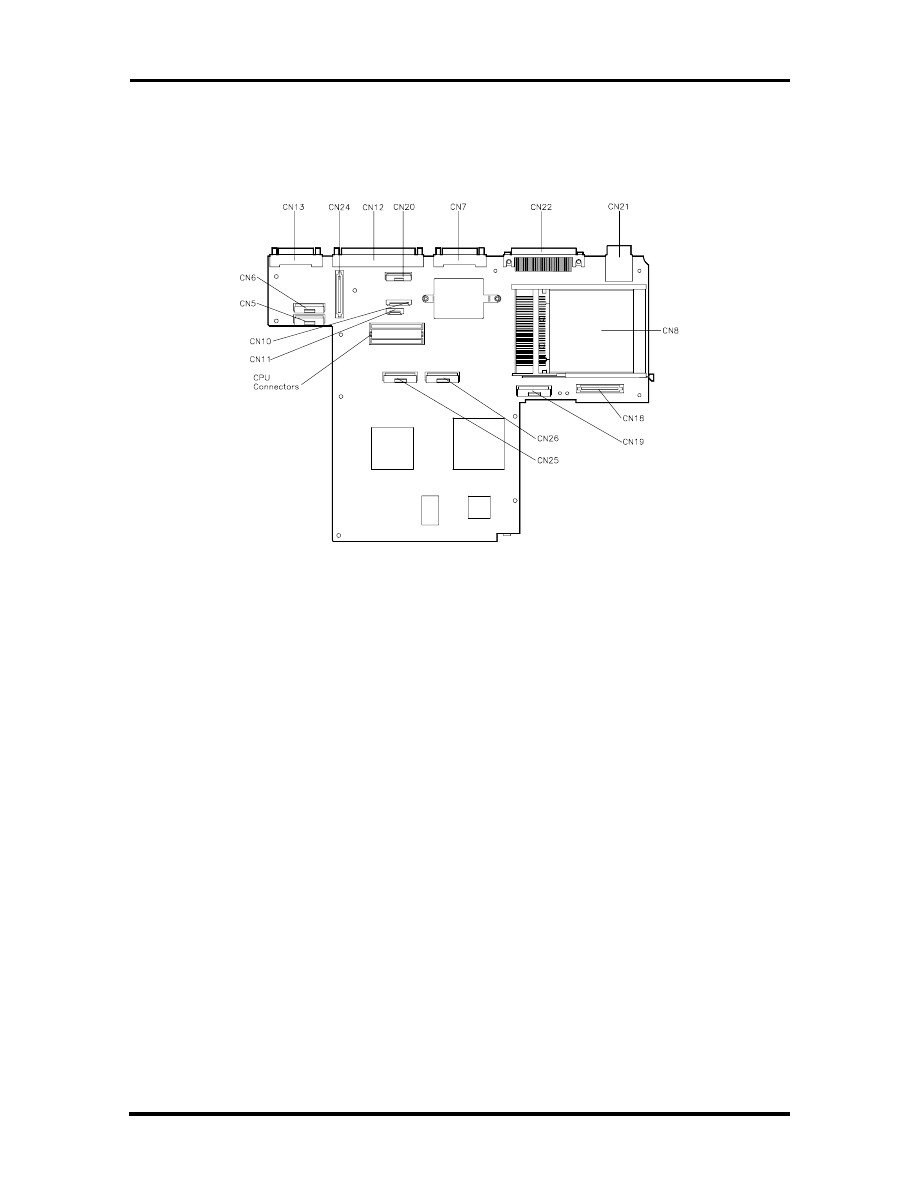
Main Board........................................................................................................... 4-18
Reassembly .......................................................................................................... 4-18
Illustrated Parts Breakdown ......................................................................................... 4-18
Service Information......................................................................................................4-22
Technical Support ........................................................................................................ 4-22
Product Information..................................................................................................... 4-23
Ordering Information from FaxFlash ............................................................................ 4-23
Appendix A Connector Locations and Pin Assignments
Appendix
B
Video
Modes
List of Figures
1-1
NEC Versa 2600 Series Notebook ................................................................. 1-1
1-2
Front View..................................................................................................... 1-3
1-3
Keyboard Layout ........................................................................................... 1-5
1-4
VersaGlide Location ...................................................................................... 1-6
1-5
Right Side Features ........................................................................................ 1-6
1-6
Left Side Features .......................................................................................... 1-7
1-7
Rear Features................................................................................................. 1-8
1-8
CPU Board Layout ........................................................................................ 1-11
1-9
Sound Board Layout ...................................................................................... 1-12
1-10
I/O Board ...................................................................................................... 1-13
2-1
AC Adapter ................................................................................................... 2-1
2-2
Powering On the System ................................................................................ 2-2
2-3
Power and I/O Connector Locations .............................................................. 2-3
2-4
NEC Versa AC Adapter................................................................................. 2-4
2-5
Battery Release Latch ................................................................................... 2-7
2-6
Inserting Battery Pack.................................................................................... 2-8
2-7
Panel LEDs and Controls ............................................................................... 2-11
SOLD BY laptopia2005 DO NOT RESELL!!
SOLD BY laptopia2005 DO NOT RESELL!!

Contents vii
2-8
Status Icons ................................................................................................... 2-12
4-1
Releasing the Battery Pack ............................................................................. 4-5
4-2
Removing the Hard Disk Drive (Step1) .......................................................... 4-6
4-3
Removing the Hard Disk Drive (Step 2) ......................................................... 4-6
4-4
Removing the Hard Disk Drive (Step 3) ......................................................... 4-7
4-5
Removing the Keyboard................................................................................. 4-8
4-6
Removing the Heat Sink/Shield Subassembly ................................................. 4-9
4-7
Removing the CPU Board.............................................................................. 4-10
4-8
Removing the LCD Assembly (Step 1) ........................................................... 4-11
4-9
Removing the LCD Assembly (Step 2) ........................................................... 4-12
4-10
Disconnecting VersaGlide Cables ................................................................... 4-13
4-11
Removing the CD-ROM Reader..................................................................... 4-15
4-12
Removing the CD-ROM Reader Assembly Screws......................................... 4-15
4-13
Removing the Bridge Battery and Diskette and Hard Drive Connector Board. 4-17
4-14
NEC Versa 2600 Series Illustrated Parts Breakdown...................................... 4-19
A-1
CPU Board Layout ........................................................................................ A-1
A-2
Main Board Layout ........................................................................................ A-2
A-3
Sound Board Layout ...................................................................................... A-3
List of Tables
1-1
Model Configurations NEC Versa 2600 Series ............................................... 1-2
1-2
Memory Map ................................................................................................. 1-14
1-3
NEC Versa 2600 Series Chip Types and Technologies ................................... 1-16
1-4
Interrupt Controllers ...................................................................................... 1-19
1-5
DMA Channel................................................................................................ 1-20
1-6
Automatic Power-Saving Features ................................................................. 1-20
1-7
Specifications................................................................................................. 1-22
2-1
I/O Connector Descriptions............................................................................ 2-3
2-2
Control and Switch Functions ........................................................................ 2-11
2-3
Fn Key Operations ......................................................................................... 2-13
2-4
POST Error Messages.................................................................................... 2-15
2-5
Setup Key Functions ...................................................................................... 2-18
2-6
Setup Parameters ........................................................................................... 2-19
2-7
Automatic Power-Saving Features ................................................................. 2-26
SOLD BY laptopia2005 DO NOT RESELL!!
SOLD BY laptopia2005 DO NOT RESELL!!

viii Contents
3-1
Quick Troubleshooting................................................................................... 3-1
4-1
NEC Versa 2600 Series Disassembly Sequence .............................................. 4-4
4-2
NEC Versa 2600 Series Field-Replaceable Parts............................................. 4-20
4-3
NEC Service and Information Telephone Numbers......................................... 4-22
A-1
CPU Board Connector ................................................................................... A-1
A-2
Main Board Connectors ................................................................................. A-2
A-3
Sound Board Connectors ............................................................................... A-3
A-4
Keyboard/Mouse Connectors ......................................................................... A-3
A-5
Serial Port Connector Pin Assignments .......................................................... A-4
A-6
CRT Connector Pin Assignments ................................................................... A-4
A-7
Parallel Printer Pin Assignments ..................................................................... A-5
A-8
Power Connector ........................................................................................... A-5
A-9
Hard Disk Drive Connector............................................................................ A-6
B-1
LCD Display Mode Setting (800x600 TFT Color LCD
and Simultaneous CRT Display)..................................................................... B-1
B-2
CRT Display Mode (CRT Only)..................................................................... B-3
B-3
Panning Video Mode (800x600 TFT Color LCD and
Simultaneous CRT Display) ........................................................................... B-4
SOLD BY laptopia2005 DO NOT RESELL!!
SOLD BY laptopia2005 DO NOT RESELL!!

ix
Preface
This service and reference manual contains the technical information necessary to set up and
maintain the following NEC Versa
®
2600 Series models:
NEC Versa 2630CD
NEC Versa 2635CD
NEC Versa 2650CD
NEC Versa 2655CD
NEC Versa 2650CDT
NEC Versa 2655CDT.
The manual also provides hardware and interface information for users who need an over-
view of the system design. The manual is written for NEC-trained customer engineers, sys-
tem analysts, service center personnel, and dealers.
The manual is organized as follows:
Section 1
Technical Information, provides an overview of the hardware and interface
components. System specifications are listed including computer dimensions, weight, envi-
ronment, safety compliance, power consumption, and system memory specifications.
Section 2
Setup and Operation, takes the authorized service technician or dealer from
unpacking to setup and operation. The section includes a description of operating controls,
setting parameters and accessing the NECCSD bulletin board system (BBS).
Section 3
Troubleshooting, lists troubleshooting procedures as well as helpful
servicing hints.
Section 4
Field Service Guidelines, provides disassembly and assembly procedures,
and an exploded-view diagram of the NEC Versa system with part numbers.
Appendix A
Connector Locations and Pin Assignments, provides a list of the main
board internal connector pin assignments and a list of external pin assignments.
Appendix B
Video Modes, lists NEC Versa supported video modes.
An Index is included for convenience.
SOLD BY laptopia2005 DO NOT RESELL!!
SOLD BY laptopia2005 DO NOT RESELL!!
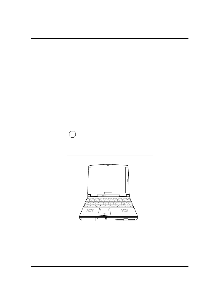
Section 1
Technical Information
The NEC Versa 2600 Series notebook computers are lightweight, compact, and fully IBM
compatible. The latest additions to the NEC Versa 2600 family include the following
models:
NEC Versa 2630CD
NEC Versa 2635CD
NEC Versa 2650CD
NEC Versa 2655CD
NEC Versa 2650CDT
NEC Versa 2655CDT.
NOTE
This service manual covers the NEC
Versa 2630CD, 2635CD, 2650CD, 2655CD,
2650CDT, and 2655CDT models only. All fig-
ures in this manual reflect these models.
Figure Section 1-1 NEC Versa 2600 Series Notebook
This section of the manual provides system configuration information, including an over-
view of hardware and interface components. See the following table for a system specific
breakdown of each model’s hardware.
SOLD BY laptopia2005 DO NOT RESELL!!
SOLD BY laptopia2005 DO NOT RESELL!!

1-2 Technical Information
Table Section 1-1 Model Configurations NEC Versa 2600 Series
Feature
2630CD
2635CD
2650CD
2655CD
2650CDT
2655CDT
CPU (Pentium)
P54CSLM
133 MHz
P55CSLM
133 MHz
P55CL,
150 MMX
P55CL,
150 MMX
P55CL,
150 MMX
P55CL,
150 MMX
On-Board RAM
16 MB
16 MB
16 MB
16 MB
16 MB
16 MB
Video Memory
1.5 MB
1.5 MB
1.5 MB
1.5 MB
1 MB
1 MB
Hard Disk Drive
1.44 GB
1.44 GB
1.44 GB
1.44 GB
1.44 GB
1.44 GB
CD-ROM Reader
10X
10X
10X
10X
10X
10X
Color LCD (12.1”)
SVGA
1
,
DSTN
2
SVGA
1
,
DSTN
2
SVGA
1
,
DSTN
2
SVGA
1
,
DSTN
2
SVGA
1
,
TFT
3
SVGA
1
,
TFT
3
Battery
NiMH
NiMH
NiMH
NiMH
LiIon
LiIon
1. Super VGA (SVGA) color display
2. Dualscan Super-Twisted Nematic (DSTN)
3
.
Thin Film Transistor (TFT)
HARDWARE OVERVIEW—FRONT
Take a moment to become familiar with the location and function of controls located on the
front of the system.
Liquid Crystal Display (LCD)
The LCD operates with the Chips & Technologies 65550B VGA controller. The controller
supports Super VGA, uses a 64 bit accelerator with a Peripheral Component Interconnect
(PCI) interface. The LCD also supports VESA timing.
The NEC Versa 2630CD, 26535CD, 2650CD and 2655CD LCD features the following:
12.1-inch Dual-STN, Cold Cathode Fluorescent Tube (CCFT) Super VGA color
LCD
0.30 mm dot pitch
16-bit digital interface
800 x 600 resolution
64,000 colors
Slide bar that adjust screen contrast.
The NEC Versa 2650CDT and 2655CDT features the following:
12.1-inch active-matrix Thin Film Transistor (TFT), Super VGA (SVGA) backlit
color LCD
0.3 mm dot pitch
SOLD BY laptopia2005 DO NOT RESELL!!
SOLD BY laptopia2005 DO NOT RESELL!!
Technical Information 1-3
18-bit digital interface
800 x 600 resolution
64,000 colors
Slide bar that adjust screen brightness.
Additional LCD panel features include a slide switch which controls adjusts screen bright-
ness.
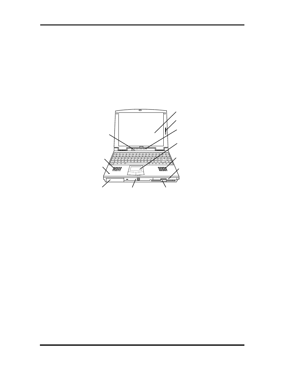
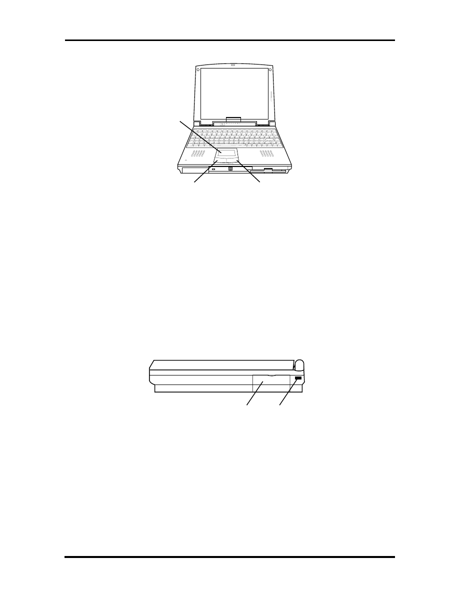
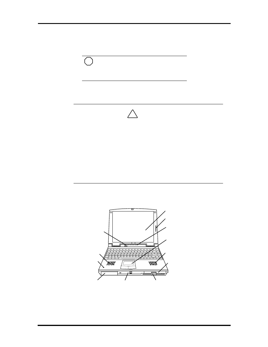
Figure Section 1-2 Front View
Another video feature includes a CRT port on the system's rear panel that allows the user to
connect an optional monochrome or color external display to the system. The computer can
support the LCD and external display simultaneously.
CD-ROM Reader
Diskette Drive
Battery Bay
Power
Button
LCD Panel
Status
LEDs
LCD Slide Bar
VersaGlide
Speaker
Speaker
Microphone
Hard Drive
NEC
SOLD BY laptopia2005 DO NOT RESELL!!
SOLD BY laptopia2005 DO NOT RESELL!!
1-4 Technical Information
Power Button
Press the power button to power on and power off the computer. The power button is a
“smart” switch, meaning that it recognizes when the system is in Suspend mode. If in Sus-
pend mode, you cannot power off until you press the power button again to bring the sys-
tem out of Suspend mode, then you are able to power off.
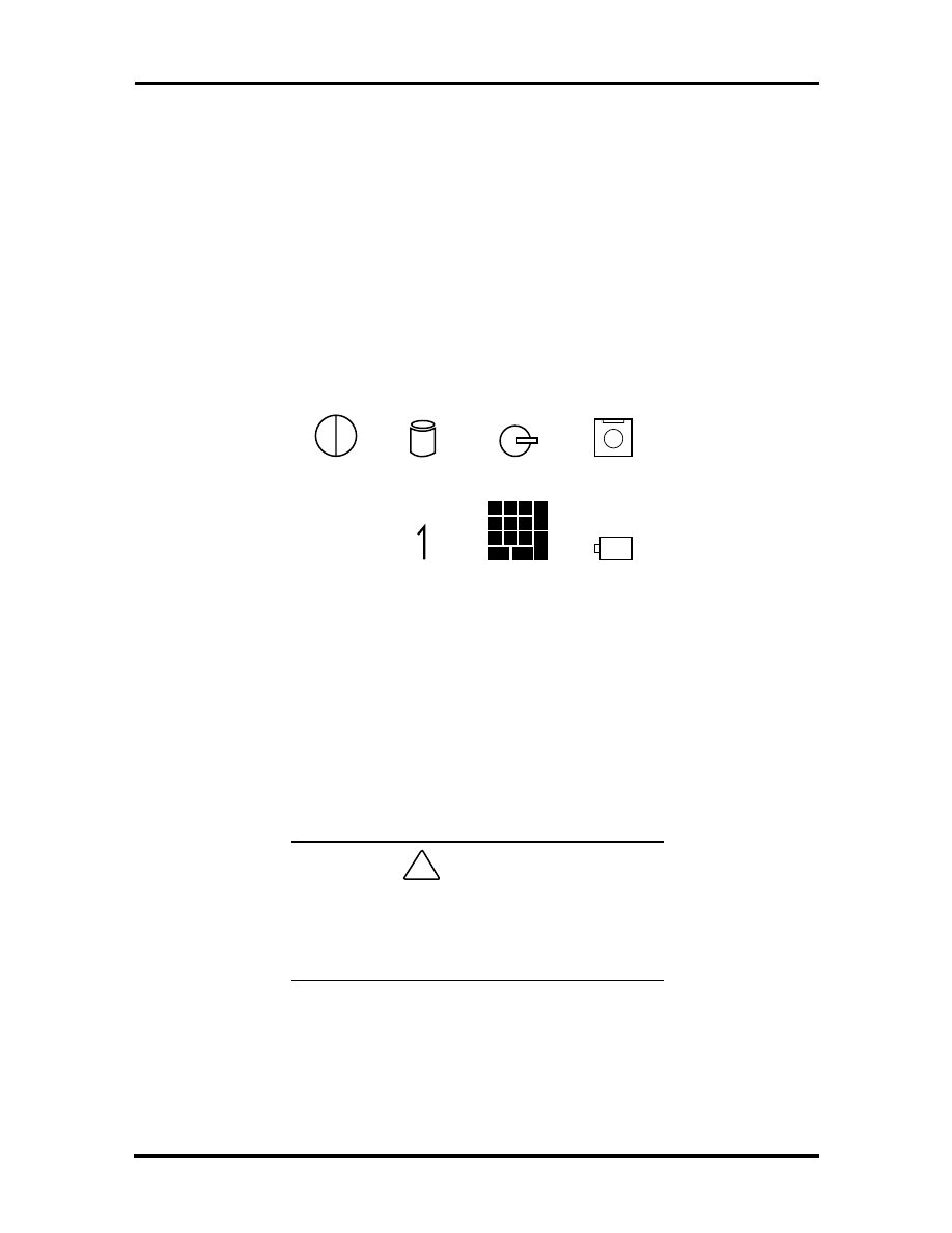
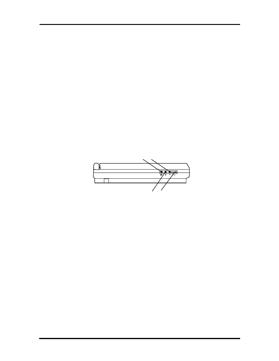
Power and Status LEDs
The Power and Status LEDs are situated right below the LCD. They provide an easy way
to detect system status. Power and Status LEDs (identified by icons) are found to the right
of the Power button and inform you of the status of your system and its components. Status
LEDs have the following meanings and light under the conditions noted:
Status LED icons
Power – Lets you know that power to the system is turned on. This LED is posi-
tioned so that you see the power state whether the LCD panel is opened or closed
lights green when the system is powered on.
lights amber when battery power is below 10%.
flashes amber when battery power is below 5%.
!
CAUTION
Be sure to save your data immediately when the
Power LED turns to yellow, flashes yellow, or
the system beeps. Failure to do so can result in
data loss.
Hard Disk Drive – Lights when the NEC Versa 2600 writes data to or retrieves
data from the hard disk drive.
CD-ROM Reader – Lights when data is read from a compact disc in the CD-
ROM drive.
A
Power
Hard
Disk Drive
CD-ROM
Reader
Diskette
Drive
Caps
Lock
Num
Lock
Pad
Lock
Battery
SOLD BY laptopia2005 DO NOT RESELL!!
SOLD BY laptopia2005 DO NOT RESELL!!
Technical Information 1-5
Diskette Drive – Lights when data is written to or retrieved from the 3.5-inch
diskette drive.
Caps Lock – Lights when Caps Lock mode is in effect.
Num Lock – Lights when Num Lock mode is active.
Pad Lock – Lights when the embedded numeric keypad lock is on.
Battery Charging Status – Lights to indicate the following:
Green – the battery is fully charged.
Amber – the battery is charging.
Light Off – the AC adapter is disconnected.
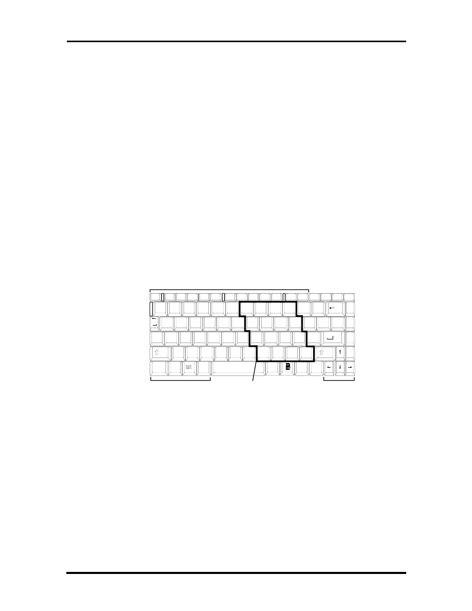
Keyboard
The built-in, 83-key keyboard (U.S.) or 79-key keyboard (UK and Germany) uses the stan-
dard QWERTY format. The keyboard provides 12 function keys and 7 cursor control keys,
with an Fn key for ROM-based key functions. The numeric keypad is embedded in the stan-
dard key layout.
Figure Section 1-3 Keyboard Layout
NEC VersaGlide
The NEC VersaGlide is a built-in mechanism that functions as the system’s mouse. It con-
trols the on-screen pointer (cursor). To use the VersaGlide, move your finger across the
NEC VersaGlide pad, and the cursor follows. The buttons below the NEC VersaGlide al-
low the user to select or deselect menu items. Tap and double-tap are supported on the
VersaGlide pad.
The PS/2 Microsoft mouse is the system’s default pointing device, driver for the NEC Ver-
saGlide. If an external mouse is installed, then the VersaGlide is deactivated. A serial
mouse is not supported.
Function Keys
Control Keys
Embedded Numeric Keypad
Cursor Control Keys
Esc
Setup
F1
F2
F3
F4
F5
F6
F7
F8
F9
F10
F11
F12
Pause
Break
Ins
Del
PrtSc
SysReq
!
1
@
2
#
3
$
4
%
5
^
6
&
7
*
8
(
9
)
0
_
-
+
=
BkSp
Scroll Lock
Home
PgUp
PgDn
End
Tab
Q
W
E
R
T
Y
U
I
O
P
{
[
}
]
|
\
Shift
A
S
D
F
G
H
J
K
L
:
;
"
'
Enter
Cap
Lock
Z
X
C
V
B
N
M
<
,
>
.
?
/
Shift
Fn
Ctrl
Alt
Alt
Ctrl
~
`
7
8
9
-
4
5
6
+
1
2
3
*
0
.
/
SOLD BY laptopia2005 DO NOT RESELL!!
SOLD BY laptopia2005 DO NOT RESELL!!
1-6 Technical Information
Figure Section 1-4 VersaGlide Location
CD-ROM Reader and Diskette Drive
A 10X CD-ROM reader and 1.44-MB diskette drive come installed in the NEC Versa
2600 Series on the front of the computer.
HARDWARE OVERVIEW—RIGHT SIDE
Review the following section for a description of the hardware on the right side of the NEC
Versa.
Figure Section 1-5 Right Side Features
VersaGlide
Right
Selection Button
Left
Selection Button
PC Card
Slots
Kensington Lock
Port
SOLD BY laptopia2005 DO NOT RESELL!!
SOLD BY laptopia2005 DO NOT RESELL!!
Technical Information 1-7
PC Card Slots
The PC card slot compartment houses two Type II devices, or one Type II and one Type III
devices. For Type III cards, insert the PC card into the upper slot. Insert the card with the
pin sockets facing towards the drive and the label facing up. To remove the PC card, push
on the Eject button to release the pin connections and slowly pull out the card.
The NEC Versa also comes with DOS/Windows PC card drivers for supporting various PC
cards like modem and network cards in Windows for Workgroups configurations.
Kensington Lock
The Kensington Lock Port gives the user the option to add an optional Kensington Lock.
HARDWARE OVERVIEW—LEFT SIDE
Review the following section for a description of the hardware on the left side of the NEC
Versa.
Figure Section 1-6 Left Side Features
Line-In — Use a cable to connect to the Line-Out port on the other audio system
to record or play.
Microphone (MIC) — Connects an external microphone for monophonic record-
ing or amplification through the unit. Plugging in an external microphone disables
the built-in microphone.
Headphones — Connects external headphones or speakers to the NEC Versa.
Plugging in headphones disables the built-in system speakers.
Volume Control — Controls the speaker or headphone volume.
Line In
Microphone
Volume
Control Dial
Headphones
SOLD BY laptopia2005 DO NOT RESELL!!
SOLD BY laptopia2005 DO NOT RESELL!!
1-8 Technical Information
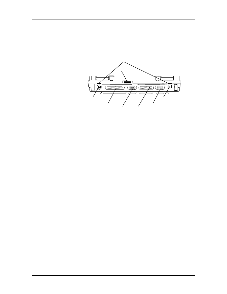
HARDWARE OVERVIEW—REAR
Review the following section for a description of the hardware on the rear of the NEC
Versa.
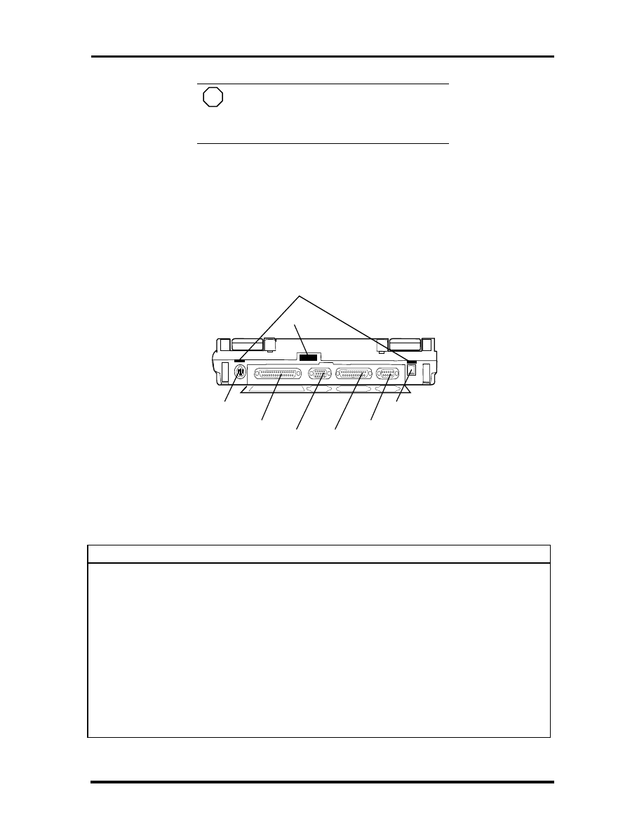
Figure Section 1-7 Rear Features
Infrared Port
This port lets you transfer files between your NEC Versa and an IR-equipped desktop or
notebook computer. You can also print to an IR-equipped printer without using cables.
Keyboard/Mouse Port
Use the standard PS/2 port to connect an external PS/2-style mouse or a PS/2-style key-
board to the system. A serial mouse is not supported through this connector nor is a Y-
adapter.
Expansion Port
This port provides a connection for NEC Versa options including the NEC Versa Port Rep-
licator 2600.
Monitor (Video) Port
Use this 15-pin port to attach an external monitor to your NEC Versa. You can run the
LCD display and the external monitor simultaneously or run either alone.
Parallel Port (LPT1)
The 25-pin printer port provides a parallel interface to which you can connect a parallel
printer or pocket network adapter. Use this port to connect a parallel printer or other par-
allel device. The port is IEEE 1284 compatible. It supports bi-directional (AT) mode, En-
hanced Capabilities Port (ECP) mode, Enhanced Parallel Port (EPP) mode, (365SL-
compatible), and bi-directional (PS/2) mode.
Serial
Port
AC Power
Port
Parallel
Port
Monitor
Port
Expansion
Port
Keyboard
Mouse Port
Port
Replicator Latch
IR Port
SOLD BY laptopia2005 DO NOT RESELL!!
SOLD BY laptopia2005 DO NOT RESELL!!

Technical Information 1-9
The parallel port’s default is PS/2 mode. Use Setup to change the default to one of the fol-
lowing.
Standard
EPP
ECP
Serial Port (COM1)
The 9-pin serial port provides a serial interface to which you can connect an RS-232C de-
vice such as an external serial printer or modem. A serial mouse is not supported.
AC/DC Power Port
Use the power jack to attach the NEC Versa to an appropriate DC power source, such as
the NEC Versa 2600 AC adapter or the optional NEC Versa 2600 DC car adapter.
HARDWARE OVERVIEW—INTERNAL COMPONENTS
Review the following sections for a description of the system’s internal hardware.
Battery Pack
The system uses a rechargeable lithium-ion (Li-Ion) battery or rechargeable nickel metal-
hydride (NiMH) as its transient power source. The battery pack installs in the compartment
next to the CD ROM reader on the front of the NEC Versa. The Li-Ion battery stores 14.4
volts with a 2700 mAh capacity and the NiMH stores 9.6 volts with a 3500 mAh capacity.
The battery pack powers the NEC Versa for approximately 1:40 to 4 hours depending on
battery type and power management choice.
When battery power is getting low, connect the AC adapter to a wall outlet and recharge
the battery. It takes 3 to 4 hours to recharge the battery.
SOLD BY laptopia2005 DO NOT RESELL!!
SOLD BY laptopia2005 DO NOT RESELL!!

1-10 Technical Information
Hard Disk Drive
A removable 2.5-inch, 1.44-GB hard disk drive ships with the system. The 1.44-GB hard
disk drive specifications are listed next.
The 1.44-GB hard disk drive specifications are listed next.
Track-to-track seek rate — 4 ms
Average seek time — 13 ms (read), 14 ms (write)
Revolutions per minute — 4009
Data transfer rate — 16.6 MB/sec
Media data rates — 39.6
− 61.8 Μ
bit/sec
Diskette Drive
The 3.5-inch 1.44-MB diskette drive is located in the front right of the system.
10X CD-ROM Reader
A 10X CD-ROM reader ships with all NEC Versa 2600 Series models. This ten-speed CD-
ROM reader features the latest in CD-ROM technology. It is located in the front center of
the system. The CD-ROM reader operates at different speeds depending on whether the CD
in use contains data or music. This improves video and sound quality.
SOLD BY laptopia2005 DO NOT RESELL!!
SOLD BY laptopia2005 DO NOT RESELL!!
Technical Information 1-11
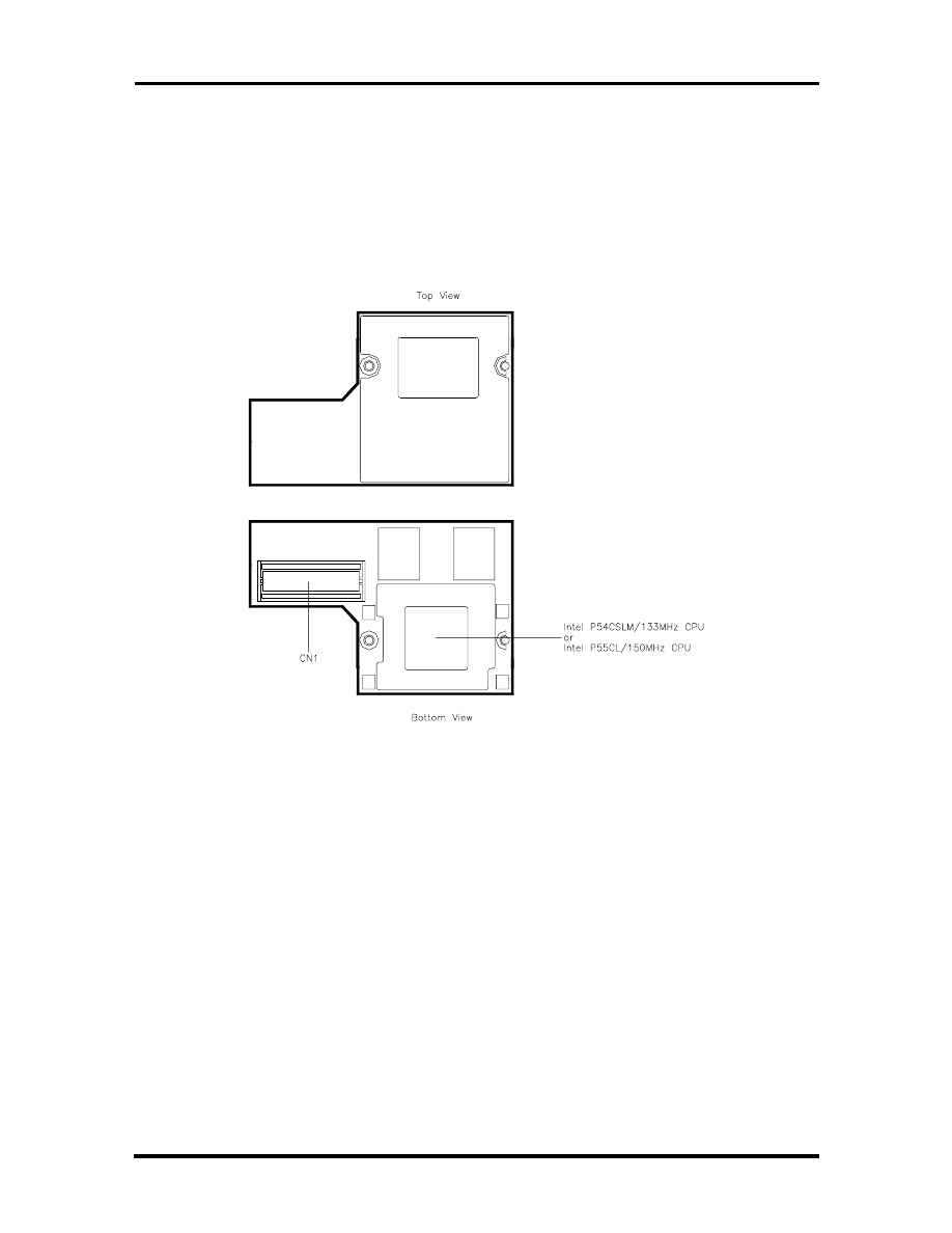
CPU Board
The CPU board is an L-shaped board situated under the keyboard.
The NEC Versa 2630CD and 2635CD models ship with Intel’s P54CSLM/133 MHz with
66 MHz bus speed. Modes 2650CD, 2655CD 2650CDT and 2655CDT ship with
P55CLM/150 MHz MMX with 60 MHz bus speed.
Figure Section 1-8 CPU Board Layout
SOLD BY laptopia2005 DO NOT RESELL!!
SOLD BY laptopia2005 DO NOT RESELL!!
1-12 Technical Information
Sound Board
The sound board provides the NEC Versa system with its audio capabilities via line-in and
headphone/microphone jacks. It is situated on top of the I/O board. The sound board inte-
grates the following features.
Figure Section 1-9 Sound Board Layout
SOLD BY laptopia2005 DO NOT RESELL!!
SOLD BY laptopia2005 DO NOT RESELL!!
Technical Information 1-13
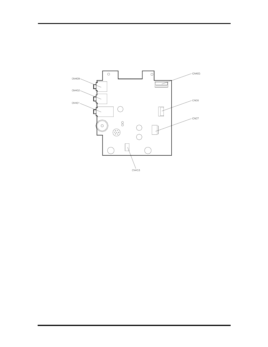
I/O Board
The system I/O board contains peripheral subsystems including serial, parallel and video
ports, PC card controller and charger.
Figure Section 1-10 I/O Board layout
Bridge Battery
The NiMH battery (3.6 Volts, 60 mAh capacity) is attached to CN23 on the underside of
the Main board. It provides battery backup and prevents data loss in the system’s comple-
mentary metal oxide semiconductor (CMOS) RAM. This memory area contains information
on the system’s configuration like date, time, drives, and memory. The bridge battery also
provides power for main battery swapping, while in suspend mode. The bridge battery lasts
approximately two years.
SOLD BY laptopia2005 DO NOT RESELL!!
SOLD BY laptopia2005 DO NOT RESELL!!

1-14 Technical Information
SYSTEM MEMORY
The system board provides 16-MB of standard random access memory (RAM).
Optional memory DIMMS with a value of 8-, 16-, or 32-MB can be added to increase sys-
tem memory up to a maximum of 80-MB (70ns Fast Page access or HyperPage access).
The DIMMS must be added in pairs of the same capacity. In addition, 256-KB of read-only
memory (ROM), 1 x 28F020, enables the system BIOS to be flashed.
The system provides 1-MB (TFT models) or 1.5-MB (DSTN model) of video RAM (60ns
HyperPage mode, self refresh).
The following Cache RAM is provided:
L1:
16KB (Internal Pentium P54C-133)
32KB (Internal Pentium P55C-150MMX)
L2: 256 KB PipeLineBurst-SRAM.
Memory Map
The system supports system and video shadowing, both controlled through complementary
metal oxide semiconductor (CMOS). The system supports BIOS as a cacheable area with
write protection. Table Section 1-2 lists the system memory map.
Table Section 1-2 Memory Map
Memory Space
Size
Function
0000000h-0009FFFFh
640 KB
DOS Applications & Optional Memory Space Gap
00A0000h-000B7FFF
96 KB
Video (VGA) Graphic Memory
00B8000h-000BFFFFh
32 KB
Text Mode Memory (SMM Space)
00C0000h-000C9FFF
40 KB
Video (VGA) BIOS
00CA000h-000CFFFFh
24 KB
PnP BIOS / PCI BIOS
00D0000h-000DFFFFh
64 KB
Setup / PCMCIA Window (Extended Memory or
Upper Memory Block)
00E0000h-000FFFFFh
128 KB
System BIOS ROM
0000000h -00FFFFFFh
16 MB
Total Base Memory
0000000h -FFFEFFFFh
80 MB
Total Extension Memory
SOLD BY laptopia2005 DO NOT RESELL!!
SOLD BY laptopia2005 DO NOT RESELL!!

Technical Information 1-15
SYSTEM VIDEO
The system's LCD operates using the Chips and Technologies 65550B VGA Controller.
Video signals travel from the controller through the system's 15-pin D-SUB connector us-
ing 5 volts.
System video integrates a PCI-bus interface. The system ships with 1 MB on TFT units and
1.5MB on DSTN of Video RAM (VRAM). It supports video modes up to 800 x 600 with
64K colors in LCD mode.
See Appendix B for a list of Video modes.
PARALLEL INTERFACE
The system's parallel interface integrates National Semiconductor’s PC87336VJG Periph-
eral I/O chip with a 25-pin D-subconnector. The port is located on the system's rear panel.
The modes of operation available for a PC87336VJG chip are:
compatibility mode
nibble mode
byte mode
Extended Capabilities Port (ECP)
Enhanced Parallel Port (EPP).
The user selects between three parallel interface modes using Auto Setup. These include
unidirectional, bi-directional or enhanced. Unidirectional mode sends data output from the
standard ISA port only. Bi-directional mode sends data using the standard ISA port or PS/2
technology. Enhanced mode enables high speed data transmission to occur using either the
unidirectional or bi-directional modes.
The default parallel port address is 378h and the interrupt level is IRQ07. Pin locations for
the parallel interface are listed in Appendix A.
SOLD BY laptopia2005 DO NOT RESELL!!
SOLD BY laptopia2005 DO NOT RESELL!!

1-16 Technical Information
SERIAL INTERFACE
The RS-232C serial port is a 9-pin connector on the system’s rear panel. The serial port
consists of a 16550A compatible serial port controller with a programmable baud rate up to
115,200 bps. The serial port connects an RS-232C device or an external modem. The de-
fault serial port address is 3F8h and the interrupt level is IRQ04.
NEC VERSA CHIP SET
Refer to Table Section 1-3 for a quick summary of the chip types used in the system. See
the Abbreviations section at the beginning of this manual for a translation of chip technolo-
gies acronyms.
Table Section 1-3
NEC Versa 2600 Series Chip Types and Technologies
Chip
Manufacturer
Description
Technology
Intel Pentium P54CSLM
Intel Pentium P55CL
Intel
Intel
133 MHz CPU
150MMX
320-pin TCP
320-pin TCP
N28F020-150
Intel
256k x 8 Flash ROM
32-pin TSOP
82C557M
Opti Viper N+
System Controller
208-pin TQFP
82C556M
Opti Viper N+
Data Path Controller
176-pin TQFP
82C558E
Opti Viper N+
PCI IDE ISA Xcelerator
208-pin TQFP
PC87336VJG
National
Semiconductor
Diskette Controller, IDE,
Parallel Interface
100-pin QFP
H8/3434
Hitachi
Keyboard Controller
100-pin TQFP
C&T 65550B
Chips &
Technologies
VGA Controller
208-pin FQFP
OZ6730D
O2 Micro
PC Card Controller
208-pin PQFP
ESS1688
ESS
Sound Controller
100-pin PQFP
Intel Pentium P55CLM Microprocessor
The 133 MHz Intel Pentium microprocessor used in the NEC Versa series computer is built
on Intel’s advanced 3.3V BiCMOS silicon technology. The CPU has power management
features. NEC adopted the chip specifically for its pipelined Floating Point Unit (FPU), and
local interrupt management.
256K X Flash ROM
The N28F020 flash ROM is a 40-pin, (TSOP). The chip allows easy updates to the system's
BIOS if needed. More specifically, the ROM is flashed electronically, installing the latest
BIOS revisions to the system. It is possible to reprogram the BIOS up to 100,000 times.
See Section 2, Setup and Operation, for BIOS update procedures.
SOLD BY laptopia2005 DO NOT RESELL!!
SOLD BY laptopia2005 DO NOT RESELL!!

Technical Information 1-17
The N28F020 provides the system upgrade capability as well as the following:
256 KB memory
Quick-Pulse Programming Algorithm
150 nanoseconds (ns) maximum access time
ETOX Nonvolatile flash technology
CMOS low power consumption
ROM BIOS
The system uses a Flash ROM known as the system's ROM BIOS to store machine lan-
guage programs. The BIOS size is 256 KB, consisting of the system utility (for PC cards,
Auto Setup), system BIOS, video BIOS, and power management.
The BIOS programs execute the power-on self-test (POST), initialize CPU controllers, and
interact with the LCD indicator panel, diskette drive, hard drive, communication devices
and peripherals. The system BIOS also contains Auto Setup and provides VGA controller
support. The ROM BIOS is copied into RAM (shadowing) for optimum performance.
The ROM BIOS contains both the system and video BIOS. The system BIOS is located in
the upper portion of the device, video BIOS is located in the lower portion. System BIOS is
located between F000h-FFFFh.
The BIOS often changes after the product release to provide enhanced features or bug
fixes. To acquire the latest BIOS release, the ROM is flashed electronically allowing the
BIOS update to occur without removing the ROM. See Section 2, Setup and Operation, for
BIOS upgrade procedures.
VGA Controller
The Chips and Technologies 65550B is a PCI 64-bit Graphics Accelerator. The integrated
programmable linear address feature accelerates the graphics user interface (GUI) perform-
ance. The controller also supports Hardware Multimedia and VESA interface standards.
The controller provides advanced power management that helps to minimize power usage
in:
normal operation
Standby (sleep) mode
panel off power saving modes.
SOLD BY laptopia2005 DO NOT RESELL!!
SOLD BY laptopia2005 DO NOT RESELL!!

1-18 Technical Information
Keyboard Controller
The keyboard controller (H8/3434) supports a PS/2-style keyboard, mouse and password
security feature. Refer to Appendix A for keyboard interface connector pin assignments.
When data is written to the output buffer, the controller generates an interrupt, and requests
the CPU to receive the data. The controller automatically adds an even parity bit to the data
sent and waits for a response. The device must acknowledge that the data was successfully
received by sending a response to the controller for each byte of data received.
PC Card Controller
The O2 Micro OZ6730D controller with the PCI bus, PC CardBus socket and configuration
registers to provide:
compliant with PCI 2.1 and 1995 PC card standards
PC Card slots with hot insertion and removal
independent Read and Write buffers for each direction
Sound Integrated Circuit
The ESS1688 chip is a single combo chip. This dynamic audio circuitry provides the fol-
lowing:
ISA 16-bit bus interface chip
audio digital processor
Plug and Play support
high performance 16-bit Sigma Delta Stereo Codec
Sound Blaster™ 16 register compatible mixer with AGC
built-in analog joystick quad timer.
SOLD BY laptopia2005 DO NOT RESELL!!
SOLD BY laptopia2005 DO NOT RESELL!!

Technical Information 1-19
Interrupt Controllers
Using interrupts, it is possible to change the system’s code sequence. To change the se-
quence, reassign the interrupt-levels. Fifteen interrupts can be used with a cascade connec-
tion of two 82C59 interrupt controllers.
Interrupt-level assignments 0 through 15 are listed in Table Section 1-4, in order of
decreasing priority. These assignments can be adjusted by PnP function.
Table Section 1-4 Interrupt Controllers
Controller
Master/Slave
Priority
Name
Device
Master
1
IRQ00
System Timer
Master
2
IRQ01
Keyboard
Master
3–10
IRQ02
Second Interrupt Controller
Slave
4
IRQ03
PCMCIA Modem Card (default)
Slave
5
IRQ04
COM1 (Internal serial port)
Slave
6
IRQ05
Sound Chip, MIDI (default)
Slave
7
IRQ06
Floppy Disk Drive Controller
Slave
8
IRQ07
LPT1 Default (internal printer port)
Slave
9
IRQ08
Real Time Clock
Slave
10
IRQ09
MIDI
Master
11
IRQ10
Not used
Master
12
IRQ11
Not used
Master
13
IRQ12
Internal Glide Pointer or External PS/2 Mouse
Master
14
IRQ13
Co-Processor
Master
15
IRQ14
Hard Drive
Master
IRQ15
CD-ROM
SOLD BY laptopia2005 DO NOT RESELL!!
SOLD BY laptopia2005 DO NOT RESELL!!
1-20 Technical Information
Table
1-5
DMA
Channel
DMA Channel
Assigned Device
DMA0
Enhanced Printer Port
DMA1
Sound Chip (default)
DMA2
FDD Controller
DMA3
Not Used
DMA4
Cascade from DMA Controller, P
DMA5
Not Used
DMA6
Not Used
DMA7
Not Used
POWER MANAGEMENT OVERVIEW
Power Management in the NEC Versa lets you conserve energy, save battery power, extend
the life of your LCD backlight, and protect against data loss due to low battery power.
Set some features to function automatically or activate them manually with the keyboard or
a button. It is wise to keep Power Management features enabled, even when using AC
power.
The system arrives set up with many power-saving features already enabled. See the fol-
lowing table.
Table Section 1-6 Automatic Power-Saving Features
Device
Default
Timeout
Comment
Video
2 minutes
Video turns off after there is no keyboard or
VersaGlide input for the specified timeout.
Hard Disk
15 seconds
Hard disk motor stops when hard disk is not accessed
for specified timeout.
Standby
2 minutes
System enters Standby mode after total system
inactivity.
You can change the timeout period for any of the devices using Setup. See Section 2 for
Setup utility procedures.
SOLD BY laptopia2005 DO NOT RESELL!!
SOLD BY laptopia2005 DO NOT RESELL!!

Technical Information 1-21
System Power Management
The system power management consists of the following operation modes. These modes
are:
Active Mode
In active mode, the system uses maximum power. It operates
with the default clock speed. The system continues to run at this speed unless
overwritten by the power management features.
Standby Mode
The system switches automatically to Standby mode. This
eliminates unnecessary power consumption when you operate the system on bat-
tery power or AC. Standby mode shuts down the LCD panel, providing privacy as
well as power savings.
Suspend Mode
Suspend mode causes the CPU power down, local devices to
shut down, and register values to be stored in RAM.
The system resumes Active mode when you press the Power button or the system
is set to resume at a certain time of day. Suspend mode lets you save power with-
out first saving the working data.
Press the Power button to enter Suspend mode when you need to be away from
the system for a short period of time and want to return to where you left off.
Local Power Management
Use Auto Setup to select one of four power management settings for local devices. These
include Maximum Battery Life, Good Battery Life, Good Performance, and Maximum
Performance. The power management levels are also available during AC operation. The
NEC Versa computer ships with Longest Battery Life as the default power management
setting. See Section 2 for specific procedures on using Auto Setup to select the power man-
agement settings.
When set to Maximum Battery Life, CMOS will set local device timeout values, a local
stand-by timeout value, and a suspend timeout value to ensure the longest battery life. The
Maximum Performance setting selects CMOS values that will provide minimal energy sav-
ings and a shorter battery life. The custom settings enable end-users to set the timeout val-
ues of their choice.
PLUG AND PLAY
The NEC Versa features Plug and Play functionality. Plug and Play is the ability of the
BIOS and/or operating system to dynamically assign system resources to a newly installed
device without user intervention.
For example, you can suspend the system, add an external keyboard, mouse, or monitor,
and when you resume working, the NEC Versa recognizes the devices that have been con-
nected to it. Similarly, you can remove external devices in Suspend mode and the NEC
Versa detects the status when resumed.
SOLD BY laptopia2005 DO NOT RESELL!!
SOLD BY laptopia2005 DO NOT RESELL!!

1-22 Technical Information
SPECIFICATIONS
Table Section 1-7 provides a complete list of NEC Versa series system specifications.
Table Section 1-7
Specifications
Item
Specification
Chassis Configuration
Size
Width: 11.7 in. (303 mm)
Depth: 9.04 in. (229.5 mm)
Height: 2.05-inch (52.0 mm)
Weight: 6.8 to 7.3 lb (3.1 to 3.3 kg), Exact weight depends on
LCD and battery type.
Keyboard
PS/2 compatible, 86-key standard (79-key for UK and
Germany) (includes Fn Key for ROM-based functions)
Device Slots
Two PC Card slots that support up to two optional cards-
oriented one on top of the other
One 3 1/2-inch x 0.75-inch high slot, front access for standard
hard disk drive
Two memory connectors for optional memory DIMM’s, located
on the bottom of system.
Power
100 to 240 Vac at 50 or 60 Hz
Output Voltage — 15 V DC, 1.8 A and 18V 1A)
Battery Pack
Li-Ion
NiMH
Weight
.88 lb (400 Kg)
Voltage
14.4 V
Capacity
2700 mAH
Battery Life
Approximately 1hr 40min to 3 hours (depending
on model and power management settings)
Recharging Time
Approximately 3 hours when the system is
on or off
Bridge Battery
Backs up memory contents up to 1 hour with
a fully charged battery in Suspend mode
Weight
1.32 lb (400 Kg)
Voltage
9.6V
Capacity
3500 mAH
Battery Life
Approximately 2 hours to 4 hours (depending on
model and power management settings)
Recharging Time
Approximately 3 hours when the system is
on or off
SOLD BY laptopia2005 DO NOT RESELL!!
SOLD BY laptopia2005 DO NOT RESELL!!

Technical Information 1-23
Table Section 1-7
Specifications
Item
Specification
Bridge Battery
Backs up memory contents up to 1 hour with a fully charged
battery in Suspend mode
Front Panel Controls
Power Button/Suspend Button
Brightness Control (TFT Model)
Contract Control (DSTN Model)
LEDs
Power LED
Hard Disk LED
CD-ROM LED
Diskette Drive LED
Cap Lock LED
NumLock LED
Pad Lock Battery
Battery Status LEDs
System Board
CPU
Intel Pentium 133 MHz or 150MHz with 256 KB L2 cache
pipeline burst SRAM, 64-bit Peripheral Component
Interconnect (PCI) bus architecture and built-in numeric
coprocessor
Clock Speed
133 Mhz or
150 MHz
CPU Bus Speed
66.6 Mhz (133 MHz)
60 Mhz (150 MHz)
Flash ROM
256 KB: E28F002BC-T1200
Connector Support
Serial — 1 port, 9-pin D-sub
Infrared —1 on rear of system, IrDA-1 compatible
VGA — 1 port, 15-pin high-density D-sub
External Keyboard/External Mouse — 1 port, PS/2, 6-pin
MiniDin (input facility will not support both devices at the same
time)
Expansion — 1 port, 200 pins for optional NEC Port Replicator
2600
Mono MIC IN — 1 port, 3-pin, Mini Pin Jack
Stereo Headphones — 1 port, 3-pin, Mini Pin Jack, .5 watts per
channel
Stereo Line-In — 1 port, 3-pin, Mini Pin Jack
DC In — 1 port, for AC adapter cable
SOLD BY laptopia2005 DO NOT RESELL!!
SOLD BY laptopia2005 DO NOT RESELL!!

1-24 Technical Information
Table Section 1-7
Specifications
Item
Specification
Memory
System Memory
16 MB EDO (On PCB Board),
Optional
2 DIMM slots, RAM may be added only by inserting 2 DIMM
cards of equal MB value.
Expandable in 8-MB, 16-MB, 32-MB
Maximum 80-MB
Video RAM
1.0-MB TFT
1.5-MB DSTN
Video Interface (VGA)
NEC Versa 2650CDT and 2655CDT models
12.1-inch high resolution active matrix Thin Film Transistor
(TFT), Super VGA (SVGA) backlit color LCD, 800 x 600 pixels
resolution, 0.3 mm dot pitch, 64,000 colors
NEC Versa 2530CD, 2635CD, 2650CD and 2655CD models
12.1-inch DSTN color LCD, 800 x 600 pixels, 0.3 mm dot
pitch, 64,000 colors
Internal Device Support
Diskette Drive
3 1/2-inch, 1.44-MB (thin-height)
Hard Disk Drives
IDE interface (built-in), 2 1/2-inch x 1-inch high (thin-height)
System ships with the 1.44-GB hard disk drive.
10x CD-ROM Reader
Ten speed CD-ROM reader
External Device Support
CRT
Displays up to 1024x 768 resolution x 256 colors
Mouse
PS/2-compatible mouse
Keyboard
Built-in 85/86-key keyboard with 12 programmable function
keys, embedded numeric keypad and special function control
keys, dedicated screen control keys, and inverted “T” cursor
keys / IBM enhanced 101/102-key compatible keyboard
SOLD BY laptopia2005 DO NOT RESELL!!
SOLD BY laptopia2005 DO NOT RESELL!!

Technical Information 1-25
Table Section 1-7
Specifications
Item
Specification
Software
Standard
Window 95, or MS-DOS
®
version 6.22
Windows
®
for Workgroups version 3.11
McAfee VirusScan™
McAfee WebScan™
Official Airline Guide (OAG
®
)
PointCast Network
Netscape Navigator
LapLink
®
Traveling Software
VideoSaver™ (Separate CD)
CardWizard™ (Windows for Workgroups Only)
MediaMatics Arcade™ MPEG Player (Win 95 Only)
Xing MPEG Player (Windows for Workgroups Only)
Microsoft Works (Windows 95 Only models)
Microsoft Money (Windows 95 Only models)
Return of Arcade (Windows 95 Only models)
Microsoft Sampler (Windows 95 Only models)
Microsoft Internet Explorer (Separate CD)
MPEG Movie (Models 2655CD and 2655CDT only)
Recommended Environment
Temperature
Operating
Storage
Transportation
41° to 104°F (5° to 35°C)
(-20° to 60°C)
(-20° to 60°C)
Humidity
Operating
Storage
Transportation
20%RH to 80%RH
10%RH to 80%RH
10%RH to 80%RH
Max Wet Bulb Temperature
Operating
Storage
Transportation
26°C
26°C
26°C
SOLD BY laptopia2005 DO NOT RESELL!!
SOLD BY laptopia2005 DO NOT RESELL!!

1-26 Technical Information
Table Section 1-7
Specifications
Item
Specification
Allowable Vibration
Operation
5 to 150Hz, 0.25G, XYZ 3 Directions
Drop Testing
Packed
Height: 90cm 10 - 15Kg
1 cornor, 3 edges, 6 faces
Administrative Compliance
U.S.: FCC, UL
Canada: CSA, DOC
Germany: VDE, TUV, CE
Australia: AS for AC adapter only
Other Compliance
PC95 Compliance
Energy Star
VESA & PnP VESA
PnP ISA
Windows 95 Logo
SOLD BY laptopia2005 DO NOT RESELL!!
SOLD BY laptopia2005 DO NOT RESELL!!
Section 2
Setup and Operation
This section provides setup and operation information for the NEC Versa series system
(including cabling, power-on verification and using the Setup utility, from this point on re-
ferred to as “Setup” only).
UNPACKING THE SYSTEM
Find an area away from devices that generate strong magnetic fields (electric motors,
transformers, etc.). Place the shipping carton on a sturdy surface and carefully unpack the
system. The carton contents include the system, AC adapter, AC power cord, battery, soft-
ware CDs, and user documentation.
HARDWARE SETUP
When connecting power and signal cables, do the following.
NOTE
Always plug the AC adapter cord into an
easily accessible outlet.
1.
The power switch turns the system on or off. Press to turn it on; press again to
turn it off.
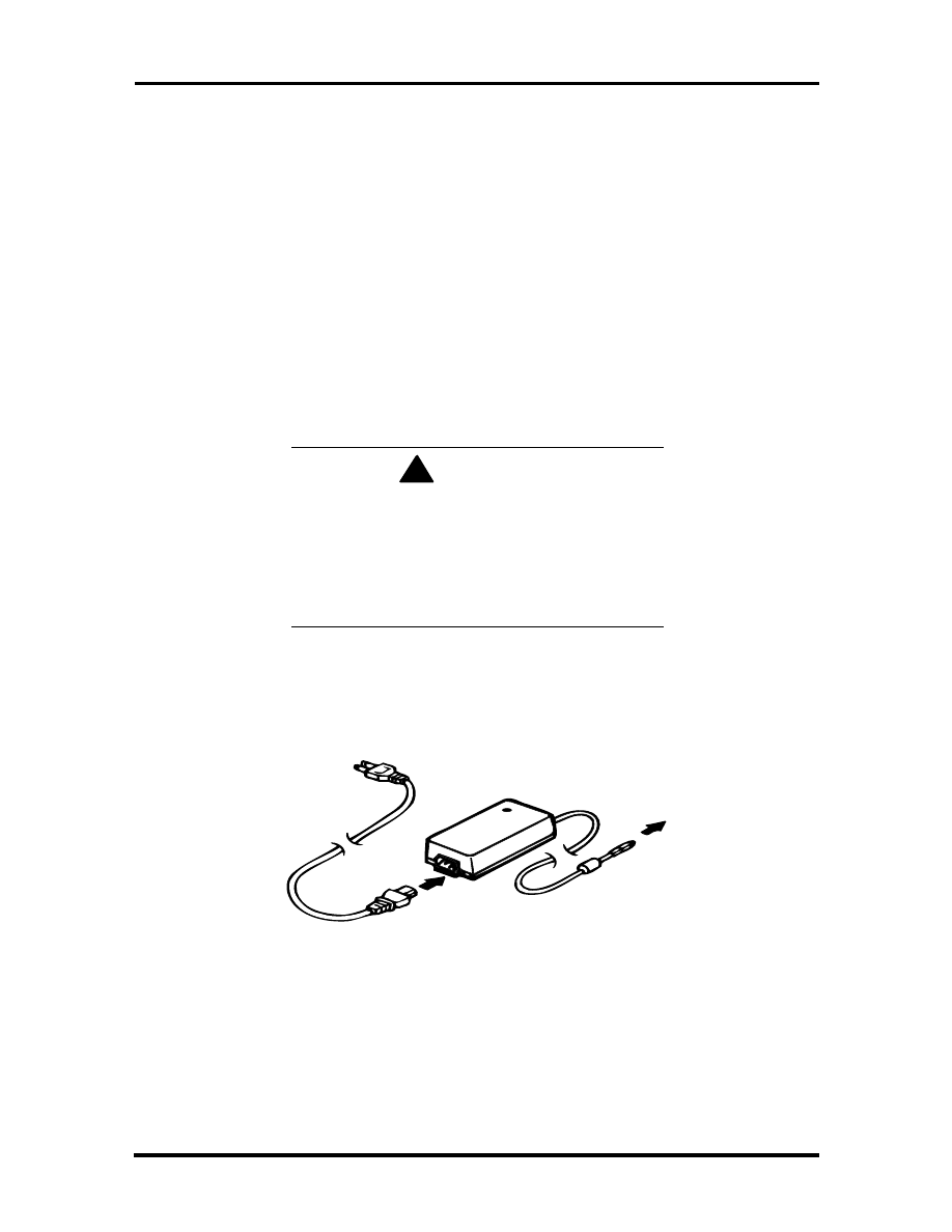
Figure
2-1
AC
Adapter
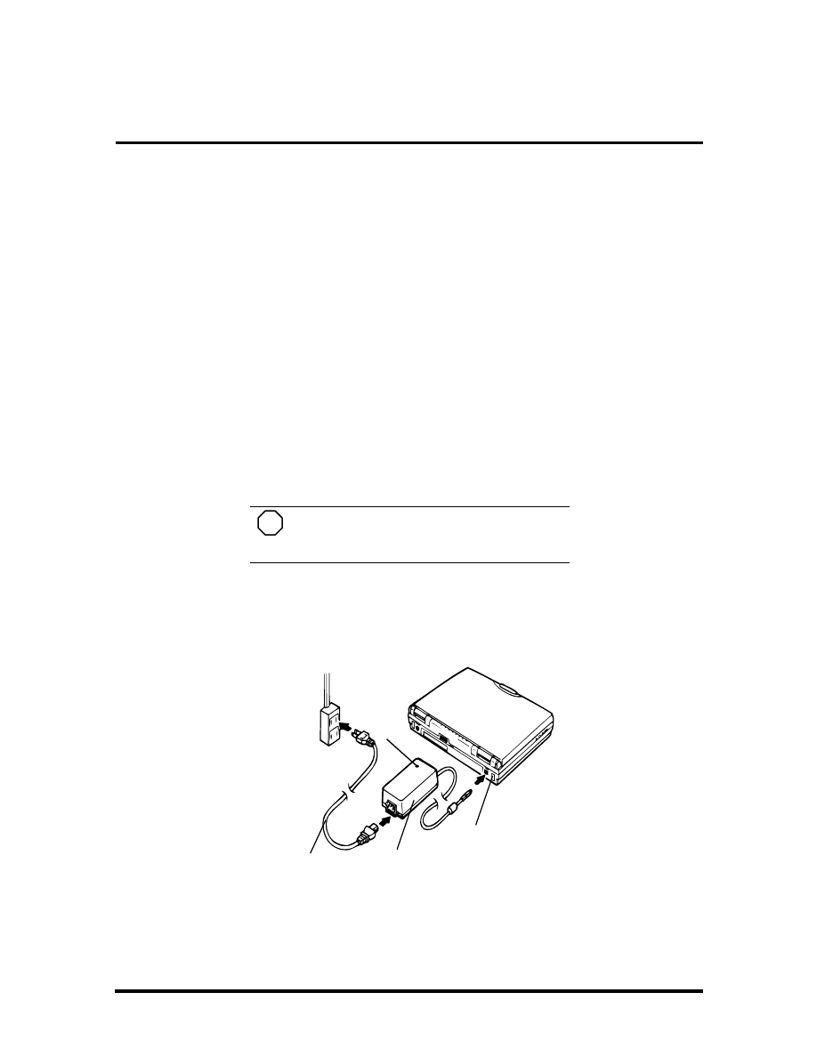
2.
Connect the AC adapter cable to the power port on back of the NEC Versa.
AC
Adapter
AC
Power Cable
AC
Power Port
LED
SOLD BY laptopia2005 DO NOT RESELL!!
SOLD BY laptopia2005 DO NOT RESELL!!
2-2 Setup and Operation
3.
Plug one end of the AC power cable into the AC adapter and the other end into a
properly grounded 120- or 240-volt wall outlet.
NOTE
Do not cover or place objects on the AC
adapter. This will allow heat to dissipate
properly.
4.
Ensure that all connections are properly seated and secure.
!
CAUTION
This equipment uses an ungrounded power cable. Replace the cord if it be-
comes damaged. U.S. and Canadian replacement cords must be UL-
approved (CSA certified in Canada) type SPT-2, 18 AWG, 2-conductor cord
with a permanently attached NEMA type 5-15P plug at one end, and a per-
manently attached connector body on the other. Cord length may not ex-
ceed 15 feet. Outside the U.S. and Canada the cord must be rated for at
least 250VAC at 10 amps, and must indicate international safety agency
approval. The plug must be a type appropriate for the country where it is
used.
Obtain replacement cords at an authorized service center. The replacement
must be of the same type and voltage rating as the original cord.
5.
Press the Power button to power on the computer.
Figure 2-2 Powering On the System
CD-ROM Reader
Diskette Drive
Battery Bay
Power
Button
LCD Panel
Status
LEDs
LCD Slide Bar
VersaGlide
Speaker
Speaker
Microphone
Hard Drive
NEC
SOLD BY laptopia2005 DO NOT RESELL!!
SOLD BY laptopia2005 DO NOT RESELL!!
Setup and Operation 2-3
NOTE
If operating the system on DC power,
verify that the system has a charged battery pack
installed.
Cable Connections
Figure 2-3 shows the external connectors for the system. Where appropriate, secure cables
by tightening the cable holding screws.
Table 2-1 describes the I/O connectors on the rear of the system. For pin assignments, see
Appendix A.
Figure 2-3 Power and I/O Connector Locations
Table 2-1 I/O Connector Descriptions
I/O Connector
Function
IR Port
The infrared port allows the transfer of files between the NEC Versa
and an IR-equipped computer, or printing to an IR-equipped printer
without using cables.
Keyboard/Mouse Port
Connects to a PS/2-style mouse, or a 101-key, external PS/2-style
keyboard.
Expansion Connector
Provides a 200-pin connector to attach the optional NEC Port
Replicator 2600.
Monitor Port
Connects to a 15-pin external CRT.
Enhanced Parallel Port
Connects to a 25-pin parallel device.
Serial Port
Connects to an RS-232C device.
Serial
Port
AC Power
Port
Parallel
Port
Monitor
Port
Expansion
Port
Keyboard
Mouse Port
Port
Replicator Latch
IR Port
SOLD BY laptopia2005 DO NOT RESELL!!
SOLD BY laptopia2005 DO NOT RESELL!!
2-4 Setup and Operation
POWER SOURCES
The NEC Versa can be powered using two different sources, as follows:
the AC adapter connected to an electrical wall outlet (using AC power)
the battery pack
The following sections summarize the power sources.
Using the AC Adapter
Use the AC adapter and power cable that came with the NEC Versa to run the computer on
alternating current (AC) power, or to recharge the battery pack. Use the AC adapter when-
ever a wall outlet is nearby.
!
WARNING
Do not attempt to disassemble the AC adapter.
The AC adapter has no user-replaceable or serv-
iceable parts inside. Dangerous voltage in the AC
adapter can cause serious personal injury or
death. The AC adapter is intended for use with a
computer. Both must meet EN60950 standards.
Keep the adapter connected whenever possible. The AC adapter charges the battery
whether or not you are using the NEC Versa.
Figure 2-4 NEC Versa AC Adapter
See the “Hardware Setup” earlier in this section for steps on connecting the AC adapter.
SOLD BY laptopia2005 DO NOT RESELL!!
SOLD BY laptopia2005 DO NOT RESELL!!
Setup and Operation 2-5
Using the Main Battery Pack
The NEC Versa 2600 Series system comes with either of two rechargeable batteries:
a Nickel Metal-Hydride (NiMH) battery pack, or
a Lithium-Ion (Li-Ion) battery pack (models 2650CDT and 2655CDT only).
NOTE
Although the battery is fully charged at
the factory, transit and shelf time may reduce the
initial battery charge. We recommend that the
first time you use your system, you connect it to
AC power using the AC adapter. This will also
recharge your battery.
Your NEC Versa 2600 Series system provides two tools to help you keep track of the main
battery's power level:
Battery Gauge utility, which lets you quickly identify how much battery power
you have available
Windows 95 Battery Gauge, which lets you quickly identify how much battery
power you have available.
When remaining battery power falls to 10%, the system emits a single beep; when battery
power falls to 5%, the system beeps once every 60 seconds.
Installing the Battery Pack
Install the battery pack in your system as follows. (For information about replacing a battery
pack, see “Replacing the Battery Pack,” later in this section.)
!
CAUTION
Be sure to save your data before replacing the
battery pack or connecting the AC adapter. Fail-
ure to do so can result in data loss.
1.
If your system is on, save your data, close any applications running, and power off
the system.
2.
Align the battery pack with the Battery Pack bay. Make sure the battery contacts
are aligned properly with the connector inside the bay. Install the battery pack
only in this bay.
SOLD BY laptopia2005 DO NOT RESELL!!
SOLD BY laptopia2005 DO NOT RESELL!!
2-6 Setup and Operation
3.
Push the battery pack into the bay until the locking latch on the bottom of the
system clicks into place.
How to Recharge the Battery Pack
When battery power gets low, connect your system to the AC adapter and AC power to re-
charge the battery pack. Your system is again ready for use and recharges during use. The
recharge time is about the same, if powered on or powered off. (see "Using the AC
Adapter.")
If AC power is not available, you can replace the battery as follows:
1.
Place your system in Suspend Mode.
2.
Remove discharged battery pack and install a charged battery pack (see
"Replacing the Battery Pack" for removal instructions).
3.
Press the Power switch to resume your system.
!
WARNING
To prevent accidental battery ignition or explosion, adhere to the following:
Keep the battery away from extreme heat.
Keep metal objects away from the battery terminals to prevent a short
circuit.
Make sure the battery is properly installed in the battery bay.
Read the precautions printed on the battery.
Battery Handling
Review the following before handling either an NiMH or an Li-Ion battery.
Use batteries only in the computer for which they are designed. Mixing other
manufacturer’s batteries can deteriorate battery and equipment performance.
Turn off power to the system after use. Keeping system power on can degrade
battery performance and shorten battery life.
Clean the battery terminals with a dry cloth if they get dirty.
When not in use, store the battery in a cool dry area.
SOLD BY laptopia2005 DO NOT RESELL!!
SOLD BY laptopia2005 DO NOT RESELL!!
Setup and Operation 2-7
The following symptoms indicate that battery life is nearing an end. Discard batteries that
display these symptoms:
shorter work times
discoloration, warping
hot to the touch
strange odor.
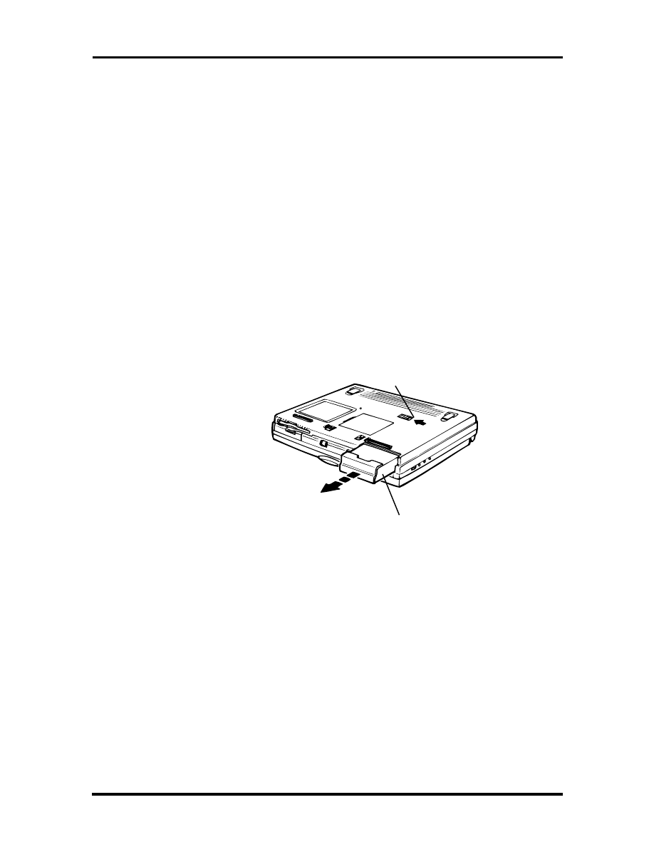
Replacing the Battery Pack
Replace the battery pack installed in your NEC Versa 2600 system as follows.
1.
Save your files, exit Windows, and turn off system power.
2.
Close the LCD and turn the system over.
3.
Press the battery release latch and slide the battery out of the system, as shown in
the following figure.
4.
Insert the new battery into the bay, pressing it firmly until the release latch clicks.
Battery
Pack
Battery
Release Latch
Figure 2-5 Battery Release Latch
SOLD BY laptopia2005 DO NOT RESELL!!
SOLD BY laptopia2005 DO NOT RESELL!!
2-8 Setup and Operation
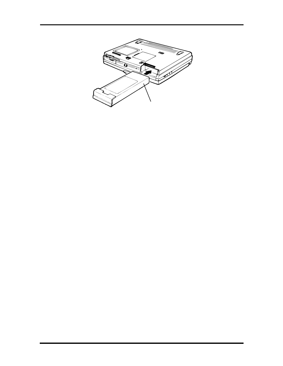
Turn the system over, open the LCD panel, and power on the system.
Battery Life
The NEC Versa 2600 battery life, on a single charge, is as follows.
For NiMH batteries
2
−
4 hours, with power management enabled
2 hours, without power management
for Li-Ion batteries
2
−
3 hours, with power management enabled
1 hour and 40 minutes, without power management
These estimates are made under the following conditions:
When the battery is new and fully charged
When no external peripherals are connected to the NEC Versa.
Your actual operation time on a single battery charge may vary significantly, depending on
the intensity of system usage.
Extending Battery Life
While on the road, it is important to be aware of the simple things you can do to extend the
life of the system’s main battery. Use the power management features enabled through
Setup to extend battery life.
Battery
Pack
Figure 2-6 Inserting Battery Pack
SOLD BY laptopia2005 DO NOT RESELL!!
SOLD BY laptopia2005 DO NOT RESELL!!
Setup and Operation 2-9
Battery Charging
The time to completely recharge your main battery is approximately 3 hours whether the
system is powered on or powered off as follows:
For maximum battery performance, fully discharge the battery before recharging it. To do
so, unplug the AC adapter, turn off power management features (through Setup and Win-
dows), and turn on the system. (Do not leave any applications running.) Once the battery is
fully discharged, plug in the AC adapter and recharge the battery.
The warning beep that sounds when battery power becomes critically low is always a true
indicator that battery power is low. Be sure to save your data when you hear the beep and
take proper steps to provide power to your system.
Battery Precautions
Always comply with the following battery precautions.
!
WARNING
There is a danger of explosion if the battery is incorrectly replaced. Replace
only with the same or equivalent type recommended by the manufacturer.
Discard used batteries according to the manufacturer’s instructions.
Keep the battery away from heat sources including direct sunlight, open
fires, microwave ovens, and high-voltage containers. Temperatures over
60ºC (140ºF) may cause damage.
Do not drop or impact the battery.
Do not disassemble the battery.
Do not solder the battery.
Do not puncture the battery.
Do not use a battery that appears damaged or deformed, has any rust
on its casing, is discolored, overheats, or emits a foul odor.
Keep the battery dry and away from water.
Keep metal objects away from battery terminals. Metal objects in contact
with the terminals can cause a short circuit and damage.
If the battery leaks onto skin or clothing, wash the area immediately with
clean water. Battery fluid can cause a skin rash and damage fabric.
If battery fluid gets into eyes, DO NOT rub; rinse with clear water im-
mediately and consult a doctor.
Take extra precautions to keep a leaking battery away from fire. There is
a danger of ignition or explosion.
SOLD BY laptopia2005 DO NOT RESELL!!
SOLD BY laptopia2005 DO NOT RESELL!!

2-10 Setup and Operation
Battery Disposal
Before disposing of the main battery, put adhesive tape on the terminals. The main battery is
made of either Nickel Metal-Hydride (NiMH) or Lithium Ion (Li-Ion).
Contact your local waste management officials for information regarding environmentally
sound collection, recycling, and disposal of batteries.
Internal Batteries
Your nickel metal-hydride or lithium Ion battery is the main power source in your NEC
Versa 2600 computer.
Appendix B lists NiMH and Li-Ion battery specifications. In addition to this battery, a
bridge battery provide power for system backup.
Extending Battery Life
While on the road, it is important to be aware of the simple things you can do to extend the
life of the system’s main battery. One way is to keep the LCD backlight setting to Low in-
stead of Medium or High. You can toggle between these three settings by pressing the
function keys,
Fn-F1
and
Fn-F2
. Or, slide the backlight control to a dimmer level.
SOLD BY laptopia2005 DO NOT RESELL!!
SOLD BY laptopia2005 DO NOT RESELL!!
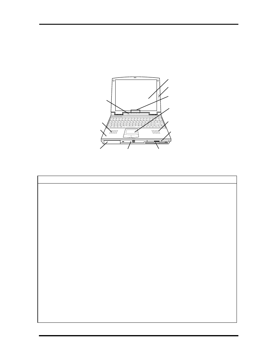
Setup and Operation 2-11
OPERATING CONTROLS
The following section describes system controls, the LEDs, and function keys.
Refer to Figure 2-7 to locate system controls and switches. Table 2-2 describes the con-
trols.
Figure 2-7 Panel LEDs and Controls
Table 2-2 Control and Switch Functions
Control
Function
Status LEDs
LEDs indicators show system status.
Power LED
Lights green when the computer is powered on. Lights amber and
blinks at low battery levels.
Power Button
Turns the system on when pushed. Turns the system off when pushed
to the right again.
Microphone
Allows the user to record monophonic sound directly into the system
Hard Disk Drive Bay
Release Latch
Push latch down to remove the hard disk drive installed in the system.
Kensington Lock
Enables the user to add an optional Kensington Lock to prevent
unauthorized use of the computer.
Volume Control
Controls the speaker or headphone volume.
Headphones
Connects external headphones or speakers to the NEC Versa.
Plugging in headphones disables the built-in system speakers.
Microphone In
Connect to an external microphone for monophonic recording.
Plugging in an external microphone disables the built-in microphone.
Line-out
Connect this port to a Line-in port on another audio system to play or
record.
Line-In
Use a cable to connect to the Line-Out port on another audio system.
AC Port
Use the power jack to attach the NEC Versa to a DC power source.
CD-ROM Reader
Diskette Drive
Battery Bay
Power
Button
LCD Panel
Status
LEDs
LCD Brightness
Control
VersaGlide
Speaker
Speaker
Microphone
Hard Drive
SOLD BY laptopia2005 DO NOT RESELL!!
SOLD BY laptopia2005 DO NOT RESELL!!
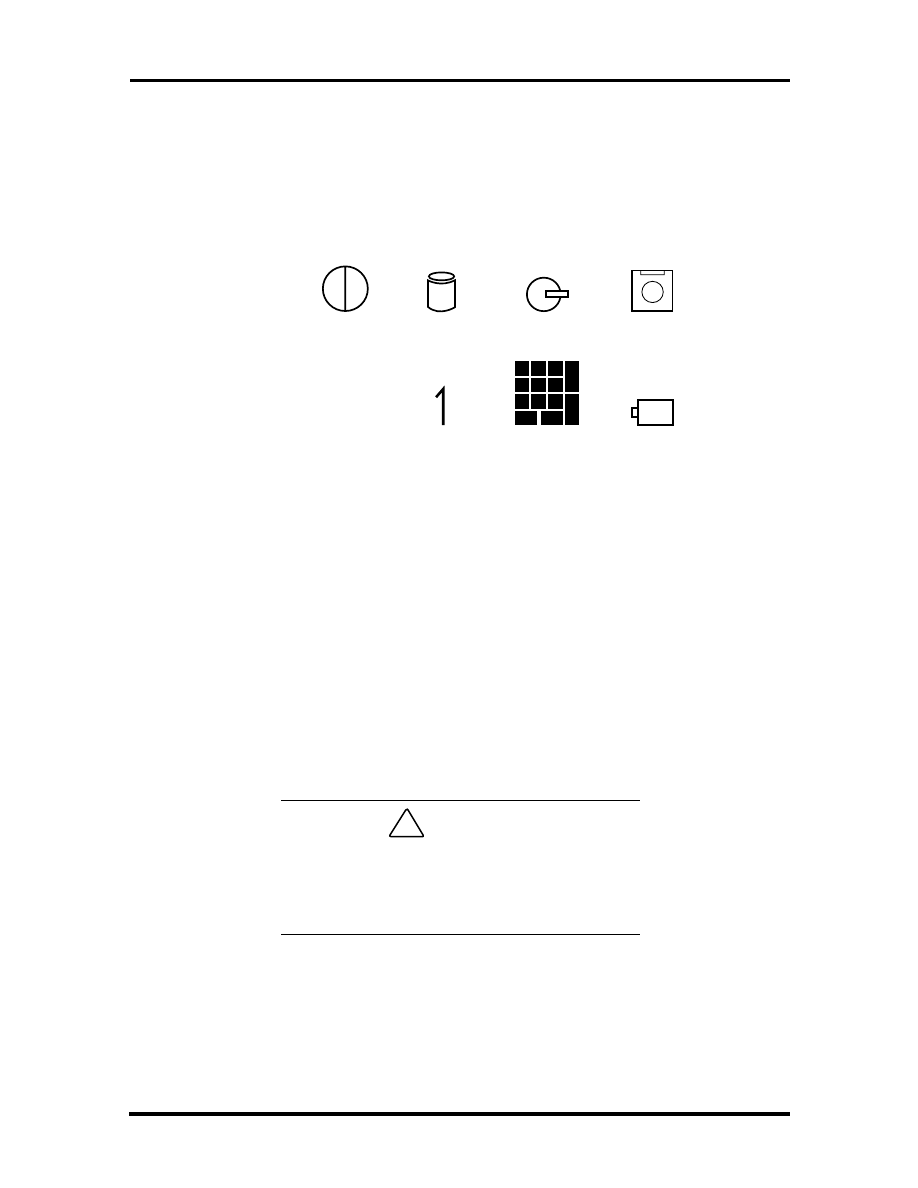
2-12 Setup and Operation
Status Icons and LEDs
The NEC Versa status information is located in the rear center of the system. Figure 2-8
shows the status icons.
Figure
2-8
Status
Icons
Status Icons
The NEC Versa uses eight icons to let the user determine system status, as follows.
Power – Lets you know that power to the system is turned on. This LED is posi-
tioned so that you see the power state whether the LCD panel is opened or
closed.
lights green when the system is powered on.
lights amber when battery power is below 10%.
flashes amber when battery power is below 5%.
!
CAUTION
Be sure to save your data immediately when the
Power LED turns to yellow, flashes yellow, or
the system beeps. Failure to do so may result in
data loss.
Hard Disk Drive – Lights when the NEC Versa 2600 writes data to or retrieves
data from the hard disk drive.
CD-ROM Reader – Lights when data is read from a compact disc in the CD-
ROM drive.
A
Power
Hard
Disk Drive
CD-ROM
Reader
Diskette
Drive
Caps
Lock
Num
Lock
Pad
Lock
Battery
SOLD BY laptopia2005 DO NOT RESELL!!
SOLD BY laptopia2005 DO NOT RESELL!!

Setup and Operation 2-13
Diskette Drive – Lights when data is written to or retrieved from the 3.5-inch
diskette drive.
Caps Lock – Lights when Caps Lock mode is in effect.
Num Lock – Lights when Num Lock mode is active.
Pad Lock – Lights when the embedded numeric keypad lock is on.
Battery Charging Status – Lights to indicate the following:
– Green – the battery is fully charged.
– Amber – the battery is recharging.
– Light Off – the AC adapter is disconnected.
Function Keys (Fn Keys)
Function keys set specific system parameters and are built into the ROM. When using these
keys, simultaneously press
Fn
and the corresponding function key. See Table 2 for a list of
ROM-based hot keys. ROM-based hot keys change system parameters temporarily. Hot
Key functions operate until the system is turned off or reset.
Table 2-3 Fn Key Operations
Key
Function
Fn-Esc/Setup
During boot-up, opens the system’s Setup program, where
you can set, view or change system parameters.
Fn-F1
Darkens the LCD brightness.
Fn F2
Brightens the LCD brightness setting.
Fn F3
LCD/CRT, toggles between LCD, CRT and simultaneous
modes.
Fn F9/NumLk
Activates the embedded numeric keypad. Hold down
Fn
,
then press a numeric keypad key to use that key (or Use Fn-
F10/PadLk
).
Updating the System BIOS
Use the following steps to update the NEC Versa system BIOS with the BIOS Update
diskette (BUD). Specifically, the BIOS is the code transmitted onto your system’s micro-
processor, or central processing unit (CPU).
SOLD BY laptopia2005 DO NOT RESELL!!
SOLD BY laptopia2005 DO NOT RESELL!!

2-14 Setup and Operation
NOTE
You only need to update the BIOS if
NEC makes significant improvements or fixes to
the current system BIOS.
If you determine that the default BIOS needs an upgrade, to receive a copy of the BUD
contact the NECCSD Versa Diskette Fulfillment Center at (800) 842-6446, or the
NECCSD Customer Service and Support (800) 632-4525, Fax (508) 635-4666, or the
NECCSD Bulletin Board (508) 635-4706.
NOTE
You should only use the BIOS upgrade
diskette for the specific model.
POWER-ON SELF-TEST (POST)
Each time the system is powered on, the system checks the working status of components
through an automatic power-on self-test (POST). The test checks the system configuration
for any discrepancies.
If the message is an Invalid Configuration message, press
<Fn> Esc
to enter the Setup util-
ity. The system collects Setup data and lists the changes detected in the current parameter
settings. While in Setup, follow the on-screen instructions to review the settings, and make
any necessary corrections.
If no error messages appear but the system still malfunctions, check the items in the follow-
ing list.
The power switch for each peripheral is on.
All cables and power cords are tightly connected.
The electrical outlet is working.
The brightness and contrast controls for the display are adjusted properly.
All options are properly installed.
NOTE
If the system parameters (date, time, op-
tions, etc.) were not been entered for the present
configuration, enter them when you complete the
setup procedures (see “System Parameters” in
this section).
SOLD BY laptopia2005 DO NOT RESELL!!
SOLD BY laptopia2005 DO NOT RESELL!!

Setup and Operation 2-15
POST Errors
Error messages appear during POST when configuration information does not match the
settings stored in memory. Error message also appear if the system loses the configuration
information due to hardware failure.
Refer to Table 2-4 for a description of POST error messages.
Table 2-4 POST Error Messages
MESSAGE
WHAT TO DO
Diskette drive failure
The diskette drive does not work or is not
properly connected.
Check that the drive is securely connected and
power is on.
Run the SCU to check the diskette drive
parameters.
If problem persists, the drive might need
repair.
Diskette read failure
Remove the diskette from the drive and try
another diskette. If you cannot read from the
next diskette, your drive might need repair.
No boot device
available
Go into the SCU and check the hard disk type
defined. Unless you had a different hard disk
installed, the setting should be “Auto.” Correct
the setting.
Invalid configuration
information – run SCU
Start the SCU, check the system parameters
set, and correct them. Exit and save the
parameters set.
Connect the AC adapter to charge the internal
backup battery. Restart the SCU and set the
correct parameters.
Real time clock failure
Set the time and date using the SCU. Exit and
save to update the parameters.
Connect the AC adapter to charge the internal
backup battery.
Time-of-day not set
Run SCU and set the time and date. Exit SCU
and save to update the time and date.
Fixed disk
configuration error
Start the SCU. Check that the hard disk type
specified is “Auto.” If not, change it to Auto
under the Hard Disk option in the Standard
menu. Exit and save to update the
parameters. If a problem still exists, the hard
disk might need repair.
SOLD BY laptopia2005 DO NOT RESELL!!
SOLD BY laptopia2005 DO NOT RESELL!!
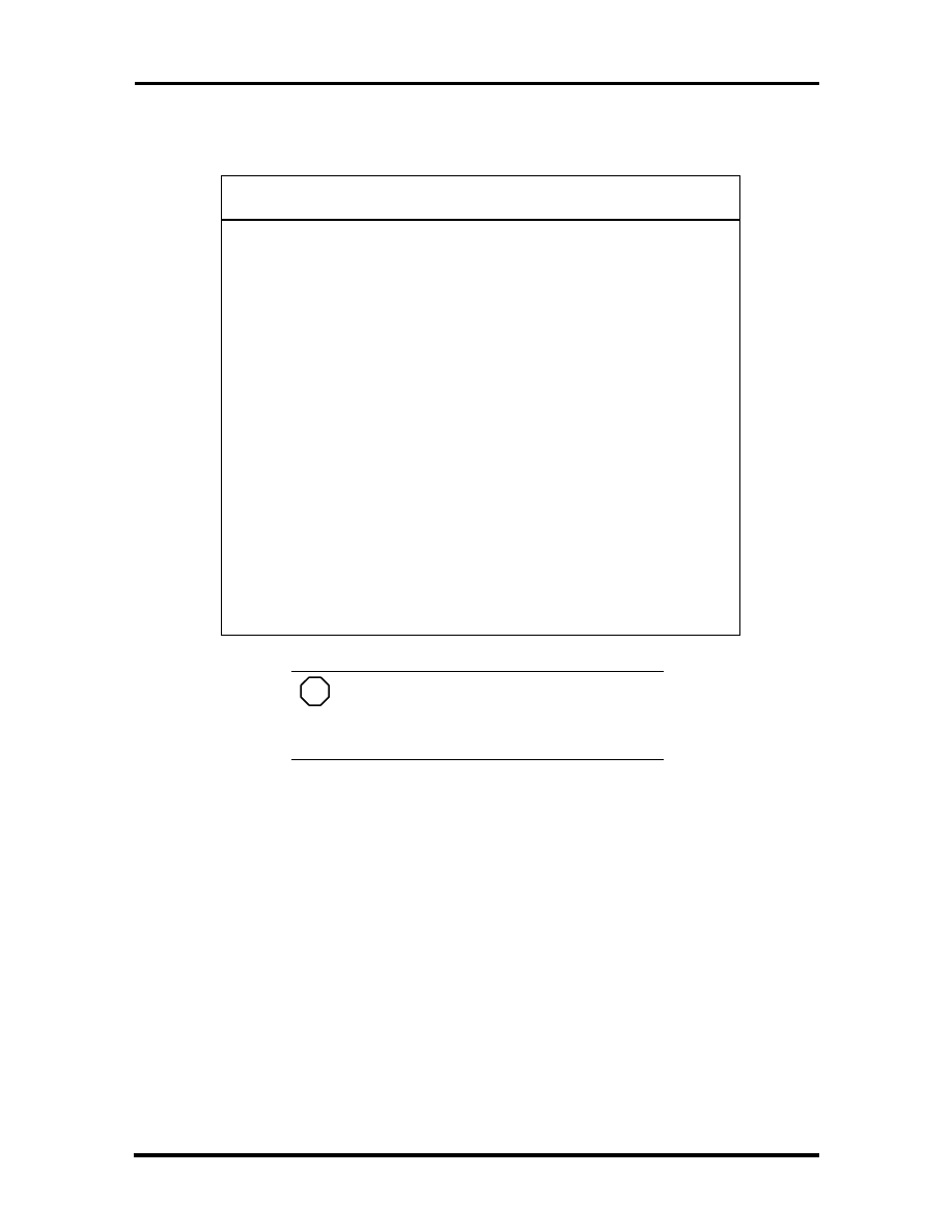
2-16 Setup and Operation
Table 2-4 POST Error Messages
MESSAGE
WHAT TO DO
Fixed disk failure
Start the SCU. Check that the disk type
specified is “Auto.” If not change it to Auto
under the Hard Disk option in the Standard
menu. Exit and save. If a problem still exists,
the hard disk might need repair.
Fixed disk controller
failure
Start the SCU. Exit and save to update the
parameters.
If problems continue, the hard disk controller
might need repair.
Keyboard clock line
failure
The keyboard might need repair.
Keyboard data line
failure
The keyboard might need repair.
Keyboard controller
failure
The keyboard might need repair.
Keyboard stuck key
failure
A key is jammed. Remove any obstructions.
If the error message remains, the keyboard
might need professional cleaning or repair.
NOTE
If a display related error occurs, it is in-
dicated by beeps. Display related errors usually
require a system board replacement.
SETUP UTILITY
The NEC Versa 2600 Setup program lets you view and set system parameters. Setup also in-
cludes security features that protect your system from unauthorized use.
Use Setup to
set the current time and date
customize your operating system to reflect your computer hardware
secure your system with a password
balance your performance needs with power conservation.
SOLD BY laptopia2005 DO NOT RESELL!!
SOLD BY laptopia2005 DO NOT RESELL!!
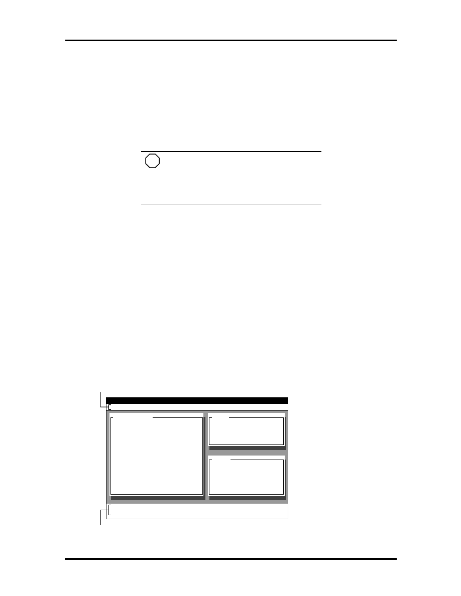
Setup and Operation 2-17
Setup Utility
How to Enter Setup
Access Setup immediately after you power on your Versa 2600, during boot up. Just press
the
Fn
and
Esc
keys simultaneously
when the following prompt appears.
<Fn - Esc> to enter System Configuration Utility
NOTE
The
Fn
key is located on the lower-left
of the NEC Versa 2600 keyboard. The
Esc
key
is located on the upper-left of the NEC Versa
2600 keyboard.
When you press
Fn Esc
and enter Setup, the system automatically displays current system
parameter settings.
How to Use Setup
The following sections describe how to use Setup, including these topics:
The Setup Screen
Using keys
Checking and setting system parameters.
The Setup Screen
The Setup screen looks similar to the one following and has five separate areas.
Startup
SystemSoft SCU
Nov 18, 1996
12:25:23 pm
Components
Security
Key
Power
Miscellaneous
Exit
Press <Alt> key to activate menus, and cursor keys to navigate. Spacebar or
<Enter> keys accept menu item. <Esc> key cancel current action.
Hard Drive
: 1031 MB
Current Display
: LCD
LCD type
: TFT (800x600)
Battery Remain
: 54%
Password
: Disable
System Information
CPU Type
= Pentium
CPU Clock
= 133 MHz
System
Base
=
640 KB
Extended
=
15360 KB
Total RAM
=
16384 KB
Cache (Ext)
=
256 KB
Memory
Menu Bar
Item Specific Help Area
SOLD BY laptopia2005 DO NOT RESELL!!
SOLD BY laptopia2005 DO NOT RESELL!!

2-18 Setup and Operation
Menu Bar
Each of the seven menu items has its own drop-down screen, where you may view
and edit the system configuration settings.
System Information
The left part of the screen. This area describes the current hardware, battery
status, and password setting.
System
The upper-right part of the screen. This area contains information about your
system’s CPU.
Memory
The bottom right part of the screen. These lines display the base and extended
memory, total RAM, and the Cache size, all in KB.
Item-Specific Help Area
The bottom of the screen describes the highlighted system configuration parame-
ter and the available settings for that parameter.
Using Keys
The following table lists Setup keys and their functions.
Table 2-5 Setup Key Functions
Key
What It Does
Alt
Activates the menu bar, by highlighting Startup.
←
→
Scrolls, left or right, along the menu bar, and highlights
the current menu selection
Enter or
Spacebar
Opens the currently highlighted menu or parameter item.
After highlighting a selection with the
↑
↓
arrows, use
the Spacebar to select a highlighted parameter setting.
Use the Spacebar or Enter for OK or Cancel.
Home/End
Moves to the first/last parameter of the currently open
drop-down screen.
↑
↓
Moves the cursor up or down among the parameters on
a drop-down menu.
Tab
For some parameter settings, moves the cursor between
the subfields. For example, for Startup / Date and Time,
Tab moves the cursor from day to month to year to hour
to minute to second, and to the OK and Cancel options.
Esc
Closes the current window or drop-down screen, de-
activates the menu bar, or closes the Setup system
configuration utility.
SOLD BY laptopia2005 DO NOT RESELL!!
SOLD BY laptopia2005 DO NOT RESELL!!

Setup and Operation 2-19
Checking/Setting System Parameters
See the following table for a list of parameters, their factory default settings, and alternate
settings. As you hightlight each parameter, its available settings are explained in the Item-
Specific Help in the bottom of the screen.
Reset the parameters on the displayed screen to their factory default settings, selecting De-
fault Values on the Exit screen.
Table 2-6 Setup Parameters
Parameter
Default
Setting
Alternate
Settings
Startup
Date and Time
Boot Device
Boot Display
Power Switch
DAY, MO, YR,
HR, MIN, SEC
Floppy Disk A/
Hard Disk C
LCD
ON/OFF
Hard Disk C
CRT, LCD and CRT
Suspend/Resume
Components
Serial / IR Ports
Serial Ports
IR Ports
COM1(3F8h)
IRQ4
COM2(2F8h)
IRQ3
COM2(2F8h) IRQ3,
COM3(3E8h) IRQ4,
COM4(2E8h) IRQ3
DISABLED
COM1(3F8h) IRQ4,
COM3(3E8h) IRQ4,
COM4(2E8h) IRQ3,
DISABLED
Parallel Port
LPT1(378h)
LPT2(278h),
LPT3(3BCh),
DISABLED
Parallel IRQ
IRQ7
IRQ5
Parallel DMAC
LPT DMA
DMA0
DMA1
Parallel Port Type
LPT Port Type
Bidirectional (PS-
2)
Standard AT
(Centronics),
EPP, ECP
Audio Base Port
220h
230h, 240h
Audio, Midi, IRQ
IRQ5
IRQ9, IRQ10, IRQ5
IRQ9,
IRQ5, IRQ11, IRQ10
IRQ9, IRQ10, IRQ11
SOLD BY laptopia2005 DO NOT RESELL!!
SOLD BY laptopia2005 DO NOT RESELL!!

2-20 Setup and Operation
Table 2-6 Setup Parameters
Parameter
Default
Setting
Alternate
Settings
Audio DMAC
DMA1
DMA0
Midi Port
330h
300h, 320h, Disabled
Speaker
Enabled
(checked)
Disabled (unchecked)
Security
Password
no password
user defined
Key
Keyboard Type
U.S.A.
U.K., French, Germany,
Japanese
Typmatic Delay
500 ms
250 ms, 750 ms, 1000
ms
Power
Maximum Battery Life
Good Battery Life
Good Performance
Maximum Performance
Disabled
Disabled
Disabled
Disabled
Enabled (checked)
Enabled (checked)
Enabled (checked)
Enabled (checked)
User Setting Battery
Video Timeout
Disk Timeout
CPU Throttle
Standby Timeout
Suspend Timeout
Brightness
Lid Close
Enabled
2 Min
15 Seconds
Good
Performance
2 Min
12 Minutes
Medium
Suspend
1, 2, 3, 4, 6, 8, 10 Min
Always On
15, 30, 45 Sec, 1, 2, 3, 4
Min, Always ON
Maximum Power
Savings,
Good Power Savings,
Maximum Performance
Always On, 1, 2, 3, 4, 6,
8, 10 Min
2, 4, 6, 8, 12, 16, 20 Min
Low, High
Standby, Backlight off
User Setting AC
Video Timeout
Disk Timeout
CPU Throttle
Standby Timeout
Suspend Timeout
Brightness
Lid Close
Always On
Always On
Maximum
Performance
Always On
Always On
High
Suspend
1, 2, 3, 4, 6, 8, 10 Min
15, 30, 45 Sec, 1, 2, 3, 4
Min
Maximum Power
Savings,
Good Power Savings,
Good Performance
1, 2, 3, 4, 6, 8 10 Min
2, 4, 6, 8, 12, 16, 20 Min
Low, Medium
Standby, Backlight off
PCMCIA Power (Suspend)
Enabled
(checked)
Disabled (unchecked)
SOLD BY laptopia2005 DO NOT RESELL!!
SOLD BY laptopia2005 DO NOT RESELL!!

Setup and Operation 2-21
Table 2-6 Setup Parameters
Parameter
Default
Setting
Alternate
Settings
Miscellaneous
Low battery beep
Wake Up Alarm
Hour
Minute
Enabled
(checked)
Disabled
Disabled (unchecked)
One Time, Every Day
User input
User input
L2 Cache
Enabled
(checked)
Disabled (unchecked)
Exit
Save and Exit
To save the
current setup
parameters (with
changes) and exit
setup.
Save and Reboot
To save the current
setup parameters, then
reboot the computer.
Exit (No Save)
To exit Setup without
saving any parameter
setting changes.
Default Settings
To restore the default
Setup settings, then
Exit.
Version Info
Displays
information about
Setup and BIOS.
As a new user, it is important to check and perhaps change the following parameter set-
tings.
Startup Menu
Date and Time
Set the System Date and Time to the current date and time. Use numerical input
(remember that the hour setting begins at 0 and ends at 23). The settings remain in
memory even after you turn off system power.
Boot Device
Select the drive you want your system to read from when the computer starts up.
Specify the boot sequence, by instructing the system to look
only to the Hard Disk, drive C
first to the Diskette, drive A, and then to drive C.
SOLD BY laptopia2005 DO NOT RESELL!!
SOLD BY laptopia2005 DO NOT RESELL!!

2-22 Setup and Operation
Boot Display
Lets you specify the system display screen as the NEC Versa 2600 LCD screen
(the default), an external CRT display, or both.
Power Switch
Lets you determine how the Power Switch (located on the hinge beneath the LCD
display) functions after the NEC Versa 2600 is powered on.
Suspend/Resume lets you use the Power Switch to save battery power. This
selection is appropriate for Windows 95 systems, which automatically power
off when you shut down the Windows 95 software.
ON/OFF (the default) turns the system on or off, and should be used by Win-
dows for Workgroups systems.
Components
This drop-down screen displays configuration settings for the serial and parallel I/O ports as
well as the sound device and speakers.
The Speaker option displays a check mark which means the system’s built-in speakers are
enabled (the default). An empty underscore means the speakers are disabled.
Security
Your NEC Versa 2600 supports a password for system security. Using the Security screen,
you can require that a password be entered at each startup or boot.
You are not prompted to enter a password until you set an initial password. Your system is
not protected until you set a password.
Once you set a password, you must enter it before your system will boot up. This feature
allows only an authorized user to access your system, including the Setup program where
you can set or change system parameters.
Setting an Initial System Password
Set an initial password as follows.
1.
Select Security from the menu bar.
2.
Open the Password screen by pressing
Enter
.
3.
Tab to the “Enter Password” field and enter a password up to eight characters
long. Press
Enter
on the keyboard.
4.
Reenter your password as prompted for verification. Press
Enter
and write your
password down and keep it in a secure place in case you forget it.
Once you have successfully set a password, a check mark appears next to the
word “Password” on the Security drop-down menu.
SOLD BY laptopia2005 DO NOT RESELL!!
SOLD BY laptopia2005 DO NOT RESELL!!

Setup and Operation 2-23
5.
Press
Esc
as many times as needed to close the screen, and to exit Setup. When
you exit Setup, be sure to save your changes reboot your system.
Removing a Password
Remove a previously set password by opening the Password screen and entering the previ-
ously set password. Press
Enter
on the keyboard. (The check mark should be removed
from the word “Password” on the Security drop-down menu.)
Key
These menu settings control how the NEC Versa 2600 keyboard functions, and includes the
following options:
Keyboard Type
Lets you select the desired keyboard format. U.S.A. is the default.
Typematic Delay
Sets the time delay between the moment a key is pressed and the time the charac-
ter appears on screen. The default is 500 milliseconds (ms).
Typematic Rate
Sets the number of characters that appear on-screen if a key remains pressed for a
second. The default is 10 characters per second (cps).
Power
The Power drop-down menu lets you balance system performance and energy conservation,
for both battery and AC operation, using the following parameters.
NOTE
Some operating systems such as Win-
dows for Workgroups and Windows 95 have
their own power management software which
overrides CMOS settings. In this case, be sure to
set your desired power management settings ac-
cordingly.
Battery Operation
Maximum Battery life
Sets power savings to a maximum and system performance to a minimum, by
running the CPU at half speed all of the time.
Good Battery life
Provides good power savings and moderate system performance, by reducing
CPU clock speed to one-half of its maximum speed any time the CPU is not en-
gaged for one-half a second.
SOLD BY laptopia2005 DO NOT RESELL!!
SOLD BY laptopia2005 DO NOT RESELL!!

2-24 Setup and Operation
Good Performance
Provides high system performance and moderate power savings, by reducing CPU
clock speed to one-half of its maximum speed any time the CPU is not engaged
for eight seconds.
Maximum Performance
Sets system performance to a maximum and power savings to a minimum, by
running the CPU at full speed all the time.
User Setting Battery (the default setting)
Lets you input your choice of performance and power saving parameters. See
“Using Power Management,” later in this chapter, for details.
AC and PCMCIA Operation
User Setting AC
Lets you set performance and power saving parameters for AC operation. Default
settings are for maximum system performance.
PCMCIA Power
Permits PC Card socket power to remain on while the system is in Suspend Mode
(see “Using Power Management.”)
Miscellaneous
Use this drop-down menu to set the following parameters:
Low battery beep (default)
This parameter lets you know when battery power is low, by emitting a beep
once, when battery power falls to 10%, and
every 60 seconds, when battery power falls to 5%.
Wake Up Alarm
Lets you specify Resume time for your NEC Versa 2600 anytime of day from
Suspend mode
one time only or
everyday at the same time.
L2 Cache
Level 2 Cache speeds up your system’s data processing time, and is enabled
(checked) by default.
SOLD BY laptopia2005 DO NOT RESELL!!
SOLD BY laptopia2005 DO NOT RESELL!!

Setup and Operation 2-25
Exit
Lets exit Setup with the following options:
Save and Exit
Saves changes, but does not reboot. The changes are effective only after the next
system startup.
Save and Reboot
Saves changes and immediately shuts down and restarts the system, so parameter
settings take effect immediately.
Exit (No Save)
Exits Setup, without saving changes.
Default Settings
Restores all Parameter settings to their default settings. Default settings take ef-
fect on the next system startup.
Using Power Management
Power Management in the NEC Versa 2600 lets you conserve energy, save battery power,
extend the life of your LCD backlight, and protect against data loss due to low battery
power.
You can set some features to function automatically or activate them manually with the
keyboard or a button.
Power Saving Modes
The NEC Versa 2600 has three different power consumption states. These include:
Active Mode — All components are turned on and active.
NOTE
Even in Active Mode, you can specify
timeouts for the LCD panel, hard disk drive and
CPU. See “Power Management Settings.”
Standby Mode — Eliminates unnecessary battery or AC power consumption.
The LCD panel, Hard Disk Drive and CD-ROM reader all shut down, and the
Keyboard Controller and CPU slow down, providing both privacy and power
savings.
To end Standby mode, press any key and return to Active mode.
Suspend Mode — Shuts down every system component, except those that
preserve unsaved data in memory, or system status and PCMCIA cards if so
configured.
SOLD BY laptopia2005 DO NOT RESELL!!
SOLD BY laptopia2005 DO NOT RESELL!!
2-26 Setup and Operation
To end Suspend mode and return to Active mode, press the Power button on the
hinge beneath the LCD panel and restart the system.
You can set your system to enter Standby or Suspend modes automatically after a
specified number of minutes of system inactivity. System activity includes key-
board, VersaGlide, diskette or hard disk drive access, PC Card modem, network,
or LAN card, serial, or printer port communications.
Power Management Settings
The system is shipped with many power-saving features already enabled. You can change
the timeout period for these devices in Setup, under the “Power” menu, with the “User Set-
ting Battery” and the “User Setting AC” parameters. The following table lists the default
settings for “User Setting Battery” operation.
Table 2-7 Automatic Power-Saving Features
DEVICE
DEFAULT
TIMEOUT
COMMENT
Video Timeout
2 minutes
Shuts off video screen after the timeout specified
elapses.
Hard Disk Timeout
15 Seconds
Stops the hard disk motor when the hard disk is
not accessed for the specified timeout.
CPU Throttle
Good Performance
CPU “clocks down” to slower speeds.
Standby Timeout
2 minutes
Specifies when the system enters Standby mode
after total system inactivity.
Suspend Timeout
12 Minutes
This setting specifies how long the system
remains in Standby mode before entering
Suspend mode.
Lid Close
Suspend
This setting determines what power-saving action
occurs when the notebook cover is closed while
the system is on.
NOTE
In Windows 95 systems, power man-
agement settings under Windows override the
settings established in Setup. Make the Windows
95 power saving settings match those in Setup
for the best results.
Using Fn-F3
Press the
Fn-F3
key combination to cycle through LCD only, CRT only, and simultaneous
display modes when an external monitor is connected.
SOLD BY laptopia2005 DO NOT RESELL!!
SOLD BY laptopia2005 DO NOT RESELL!!
Section 3
Troubleshooting
This section focuses on providing you with some information on basic troubleshooting as
well as how to translate some system error messages.
QUICK TROUBLESHOOTING
The following table summarizes problems that may develop during system operation and
lists suggested corrective actions.
Table 3-1 Quick Troubleshooting
Problem
Corrective Actions
No power
Check that the AC adapter is plugged into the
power connector of the system. Also, check that
the AC adapter is plugged into a properly
grounded AC power outlet.
If using the battery as the main power source,
check if the battery pack is the right type, is
charged, and is inserted correctly.
Check the powerboard of the system. Is it
inserted into the main board connector properly?
Otherwise, replace the powerboard.
Data on the LCD is unreadable
Adjust the brightness control on the right side of
the LCD panel.
Check if the LCD cables are inserted properly.
Also, check connections inside the LCD panel.
Check if the installed VGA driver is correct.
Check the VGA controller chip on the main board
for any loose solder.
Replace the main board.
SOLD BY laptopia2005 DO NOT RESELL!!
SOLD BY laptopia2005 DO NOT RESELL!!

3-2 Troubleshooting
Table 3-1 Quick Troubleshooting
Problem
Corrective Actions
Battery power does not last long
Make sure that power management features are
enabled.
Recharge the battery pack for 1½ hours before
using again.
Replace the battery pack.
System halts during boot sequence
Check the condition of selected boot device
(diskette or hard disk) for bad boot track or
incorrect OS files.
Try booting from a new bootable diskette and
recopy or repartition hard disk.
Check for any BIOS error messages on the
screen.
Replace the main board.
I/O processing malfunctions
Check the connections of all internal devices.
Replace the main board.
Diskette drive does not work
Check that the diskette drive cable is connected
properly.
See diskette type is correct and not faulty.
Replace the diskette drive.
Replace the main board.
Hard disk drive malfunction
Check if hard disk drive is set properly on
CMOS.
Check if disk drive is good.
Replace the main board.
Memory malfunction
Check that the memory module is inserted
properly.
Replace the memory card.
Replace the main board.
External keyboard or PS/2 mouse
doesn’t work
Check that the keyboard or mouse is connected
properly. Power off system first before plugging
in the device.
Replace the keyboard or mouse.
Replace the main board.
SOLD BY laptopia2005 DO NOT RESELL!!
SOLD BY laptopia2005 DO NOT RESELL!!
Troubleshooting 3-3
Table 3-1 Quick Troubleshooting
Problem
Corrective Actions
PC card does not work
Check the PC card driver installation for any IRQ
or I/O address conflict.
Check that the PC card is inserted properly and
all connections are set.
If the PC card is a Type II card, install it in the
system’s other PC card slot.
Replace the PC card.
Replace the main board.
NEC VersaGlide doesn’t work
Check that the mouse driver is properly installed.
Check that the VersaGlide cable inside the
system is inserted properly.
Remove the VersaGlide and clean it.
Check the keyboard controller chip for any cold
or loose solder.
Replace the main board.
Serial device does not work
Check that the serial device driver is installed
properly.
Check that the serial device is connected
properly.
Replace the serial device.
Check the I/O controller chip on the main board
for any cold or loose solder.
Replace the main board.
Parallel device does not work
Check all connections.
Check that the external device is turned on.
Test another parallel device.
Check the I/O controller chip on the main board
for any cold or loose solder.
Replace the main board.
SOLD BY laptopia2005 DO NOT RESELL!!
SOLD BY laptopia2005 DO NOT RESELL!!

3-4 Troubleshooting
HELPFUL QUESTIONS
Here are some helpful questions to ask when troubleshooting the system:
Is there any external power source connected to the computer?
Is the battery fully charged?
Is the computer turned on and the Power LED activated?
Are the LCD display controls set to the minimum level?
Is the LCD display switched to the external monitor?
Are all cables and devices connected properly and securely?
Are all needed device drivers installed properly?
Have you checked the AUTOEXEC.BAT and CONFIG.SYS files for errors?
Is Suspend mode activated? (Press any key or press the Power switch to return
the system to active mode.)
SOLD BY laptopia2005 DO NOT RESELL!!
SOLD BY laptopia2005 DO NOT RESELL!!

Section 4
Field Service Guidelines
This section contains preventive and corrective maintenance procedures for the following
NEC Versa 2600 Series models:
NEC Versa 2630CD
NEC Versa 2635CD
NEC Versa 2650CD
NEC Versa 2655CD
NEC Versa 2650CDT
NEC Versa 2655CDT.
Section 4 is broken into four sections, which are presented in the following order:
“Preventive Maintenance” describes cleaning procedures and preferred handling
procedures for sensitive components (for example disk drives, batteries).
“Disassembly and Assembly” identifies all field replaceable parts with the re-
mainder of the section containing the removal and replacement procedures for the
field replaceable parts.
“Illustrated Parts Breakdown” contains an exploded view diagram and a listing of
field replaceable parts with part numbers.
“Service and Product Information” lists NEC service and information telephone
numbers.
PREVENTIVE MAINTENANCE
Preventive maintenance is limited to cleaning the plastic case, the keyboard, the display
screen, and the diskette drive heads as required.
NOTE
Remove the battery and disconnect the
AC adapter before performing any maintenance.
Voltage is present inside the system unit and
LCD even after the system is turned off.
SOLD BY laptopia2005 DO NOT RESELL!!
SOLD BY laptopia2005 DO NOT RESELL!!

4-2 Field Service Guidelines
Cleaning the Notebook Exterior
Use the steps below to clean the outer surface of the system.
1.
Power off the system and remove all battery packs. Unplug all cables connected
to the system.
2.
Wipe the outside of the system, keyboard, and display with a soft, clean cloth.
Remove stains with a damp, almost dry cloth. Use glass cleaner to clean the
LCD. Apply the glass cleaner directly to the cloth and then wipe the LCD. Do not
use solvents or strong, abrasive cleaners on any part of the system.
3.
Clean the keys with a damp cloth. A small, soft-bristle brush may be used to
clean between the keys. Make sure to use a damp cloth (not wet) to prevent
moisture from seeping between the keyboard and the metal plate, possibly dam-
aging the components under the keys. If the keyboard gets wet, thoroughly dry it
before reassembling the system unit.
Cleaning the Notebook Interior
When servicing the inside of the notebook, remove dust and other foreign particles from
inside the system unit as follows.
1.
Remove the top cover and keyboard using the disassembly procedures discussed
later in this section.
2.
Dust or vacuum (with a rubber-tipped nozzle) the inside of the system,
particularly the motherboard surface. Use care to avoid damaging or dislodging
any components or cables.
3.
Inspect all cables connectors for damage. Ensure that connectors are seated prop-
erly before replacing the cover.
Protecting the Disk Drives
To protect the disk drives and data, back up the system disk periodically on diskettes. Peri-
odically use a head-cleaning diskette in the disk drive to prolong the life of the drive and to
help maintain data integrity.
Here are some maintenance procedures to use when servicing a hard disk:
Always back up the data files from the hard disk.
Run a virus detecting program to check for possible virus infected areas on the
hard disk.
Use the preinstalled ScanDisk program to correct any errors found in the direc-
tory and File Allocation Table (FAT). This also frees up space from any unused
sectors.
SOLD BY laptopia2005 DO NOT RESELL!!
SOLD BY laptopia2005 DO NOT RESELL!!

Field Service Guidelines 4-3
Never turn the computer off when the hard disk is being accessed.
Never move or raise the computer while the hard disk is being accessed. Be
especially careful not to jar the hard disk during access; this can cause a hard disk
crash.
Acquire a hard disk maintenance program like DEFRAG under DOS, or Norton
Utilities SPEEDISK programs. These programs reorganize your hard disk by
eliminating fragmentation and improves the hard disk access time.
Handling the Battery Packs
The battery packs furnished with the computer require reasonable care and handling to en-
sure efficient operation and maximum life. Periodically inspect the battery terminals and
the batteries for evidence of corrosion and oxide build-up.
To ensure that the battery packs endure for a normal life cycle, always observe the follow-
ing precautions when handling the battery packs:
Do not drop the battery packs or subject them to excessive shock and vibration.
Do not expose the battery packs to direct sunlight, moisture, chemical com-
pounds, or extreme heat.
Do not disassemble the battery packs.
Do not use the battery packs to power other devices.
Do not short the battery leads or connect the battery with reversed polarity.
Never attempt to charge the battery packs in any way other than as described in
this manual and the user’s guide.
Always charge the battery packs as soon as possible after a low battery indica-
tion.
Maintaining the LCD Quality
When it comes to screen problems, heat plays a big part. After a good working session, the
typical routine is to shut the machine and close the cover. The display surface (no matter
what type it is) radiates heat. When you close the cover, you trap the heat against the
screen. Make sure to leave the computer's cover open for about ten minutes while the heat
disperses, before closing the LCD.
SOLD BY laptopia2005 DO NOT RESELL!!
SOLD BY laptopia2005 DO NOT RESELL!!

4-4 Field Service Guidelines
DISASSEMBLY AND REASSEMBLY
This section contains step-by-step disassembly procedures for the system. Reassembly is
the reverse of disassembly. Each procedure is supported by a simplified disassembly illus-
tration to facilitate removal. The Illustrated Parts Breakdown and parts lists for the system
unit are shown later.
For complete disassembly of the system, follow the disassembly order listed in
Table 4-1. To reassemble, follow the table in reverse order.
Table 4-1 NEC Versa 2600 Series Disassembly Sequence
Sequence
Part
See Page
1
Battery Pack
4-5
2
Hard Disk Drive
4-6
3
Keyboard
4-7
4
Heat Shield and CPU Board
4-9
5
LCD and Top Cover
4-11
6
VersaGlide Assembly
4-13
7
Sound Board
4-14
8
LED Status Board and IR Board
4-15
9
10X CD-ROM Reader and Heat Shield
4-15
10
Bridge Battery and FDD/HDD Connector Board
4-16
11
Diskette Drive
4-17
12
Power Board
4-18
13
Main Board
4-18
When disassembling the system unit, follow these general rules.
Turn off and disconnect all power and all options, including the AC adapter (if
connected) and battery packs (see the procedures that follow).
Do not disassemble the system into parts that are smaller than those specified in
the procedure.
Label all removed connectors. Note where the connector goes and in what posi-
tion it was installed.
SOLD BY laptopia2005 DO NOT RESELL!!
SOLD BY laptopia2005 DO NOT RESELL!!
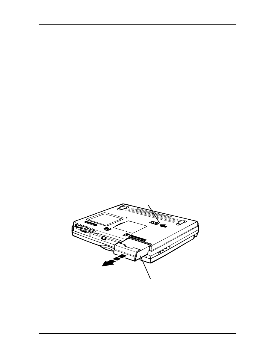
Field Service Guidelines 4-5
Required Tools and Equipment
All NEC Versa corrective maintenance procedures can be performed using the following
tools:
Tweezers
Small flat-head screwdriver
Small Phillips screwdriver
Small Hex-bolt screwdriver
Small utility knife
Rubber finger tip
Right angled dentist style probe.
Battery Pack
Remove the battery pack installed in the NEC Versa 2600 system as follows.
1.
Make sure the power is off.
2.
Close the LCD and turn the system over.
3.
Press the battery release latch and slide the battery out of the system.
Battery
Pack
Battery
Release Latch
Figure 4-1 Releasing the Battery Pack
SOLD BY laptopia2005 DO NOT RESELL!!
SOLD BY laptopia2005 DO NOT RESELL!!
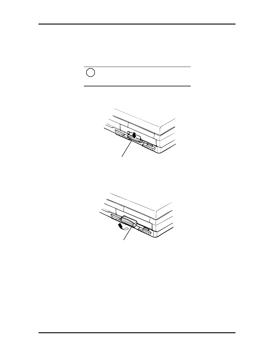
4-6 Field Service Guidelines
Hard Disk Drive
Make sure your NEC Versa is powered off, all external options are disconnected, and the
LCD panel is closed. Then perform the following steps:
NOTE
The NEC Versa must be powered off while
the hard drive is being removed and installed.
1.
Pull down the hard drive latch located on the right front of the computer.
Pull Down
Hard Drive Latch
Figure 4-2 Removing the Hard Disk Drive (Step 1)
2.
Pull the hard drive latch forward as shown next.
Pull Out
Hard Drive Latch
Figure 4-3 Removing the Hard Disk Drive (Step 2)
3.
Continue pulling on the latch until you remove the hard drive from its bay.
SOLD BY laptopia2005 DO NOT RESELL!!
SOLD BY laptopia2005 DO NOT RESELL!!
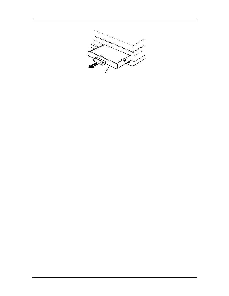
Field Service Guidelines 4-7
Hard Drive
Figure 4-4 Remove Hard Disk Drive (Step 3)
Keyboard
Remove the keyboard from the system as follows.
1.
Insert a fine flat head ceramic tip screwdriver between the following keys to re-
lease the four locking tabs that secure the keyboard.
Fn
and
Ctrl
Alt
and
Space Bar
Space Bar
and
Alt
Ctrl
and the key to the right that contains
the Tilde
(~)
2.
Use the same screwdriver to gently lift the front edge of the keyboard up and to-
wards the LCD screen.
3.
Disconnect the two Keyboard cables from Connectors CN10 and CN11 on the
Main board.
4.
Remove the Keyboard from the system.
SOLD BY laptopia2005 DO NOT RESELL!!
SOLD BY laptopia2005 DO NOT RESELL!!
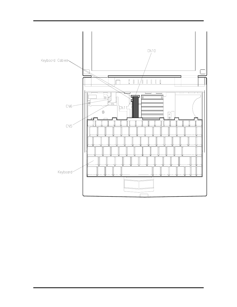
4-8 Field Service Guidelines
Figure 4-5 Removing the Keyboard
SOLD BY laptopia2005 DO NOT RESELL!!
SOLD BY laptopia2005 DO NOT RESELL!!
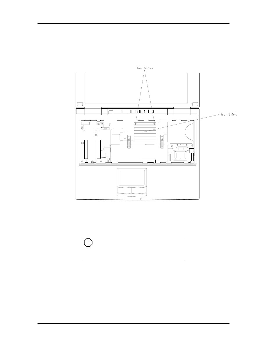
Field Service Guidelines 4-9
Heat Shield and CPU Board
Removing the CPU board entails, first removing the heat sink and heat shield as follows.
Figure 4-6 Removing the Heat Sink/Shield Subassembly
NOTE
When disassembling the laptop keep
screws and stand offs with their proper
subassemblies to insure proper reassembly.
1.
Remove the following items
three screws securing the heat sink and heat shield
one screw securing the LCD ribbon cables to the heat shield
LCD ribbon cables (disconnect) from connectors CN5 and CN6 on the main
board.
SOLD BY laptopia2005 DO NOT RESELL!!
SOLD BY laptopia2005 DO NOT RESELL!!
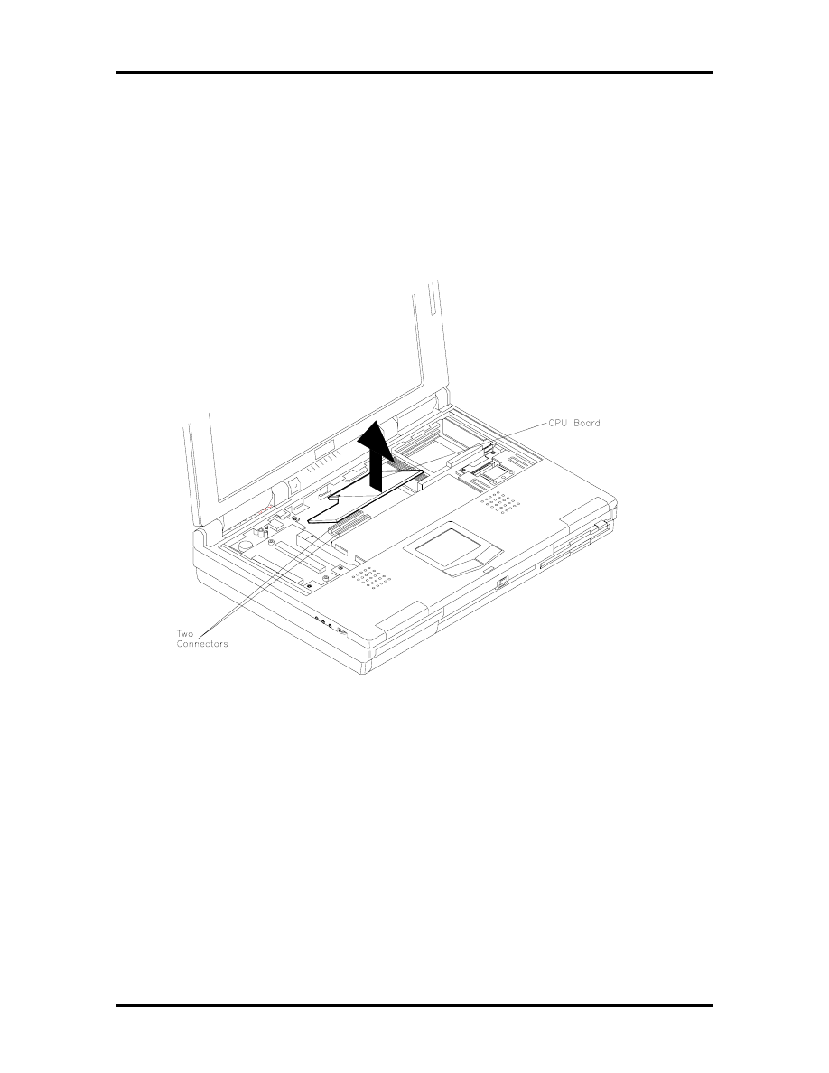
4-10 Field Service Guidelines
2.
To lift out the heat sink/shield subassembly. Lift at the location shown in Figure
4-6 and gently move this corner in a clockwise direction while lifting up on the
heat/shield subassembly and at the same time gently apply a slight outward press
to the plastic forward of the inboard right latch cover.
3.
Now lift the front edge of the CPU board gently until the CPU board separates
the connectors on the main board.
Figure 4-7 Removing the CPU Board
SOLD BY laptopia2005 DO NOT RESELL!!
SOLD BY laptopia2005 DO NOT RESELL!!
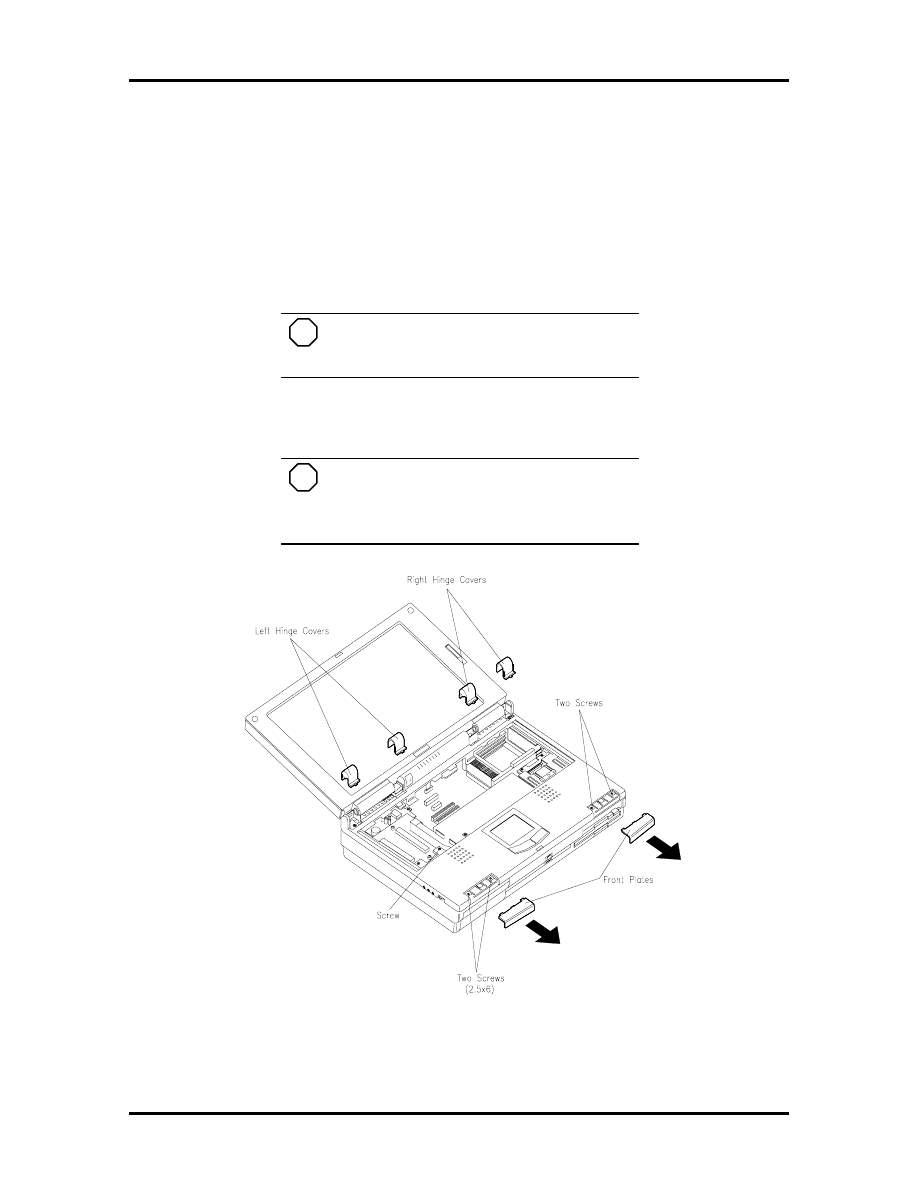
Field Service Guidelines 4-11
LCD and Top Cover
Remove the LCD and top cover as follows.
1.
Remove the front plates as follows.
Remove the two front plates from the hand rest area on the laptop. It is rec-
ommended that you wear a rubber finger tip for gripping ease and slide the
plates from the laptop.
NOTE
During reassembly there is a left and a
right front plate.
¦
Remove two screws from each bay.
NOTE
During reassembly the screw under the
left plate are (2.5 x 6) and (2.5 x 3.5) under the
right plate.
Figure 4-8 Removing the LCD Assembly (Step 1)
2.
Remove two each Left and Right Hinge covers by inserting a ceramic tip screw
driver or fingernail in the notch on the rear of the each of the hinge covers.
SOLD BY laptopia2005 DO NOT RESELL!!
SOLD BY laptopia2005 DO NOT RESELL!!
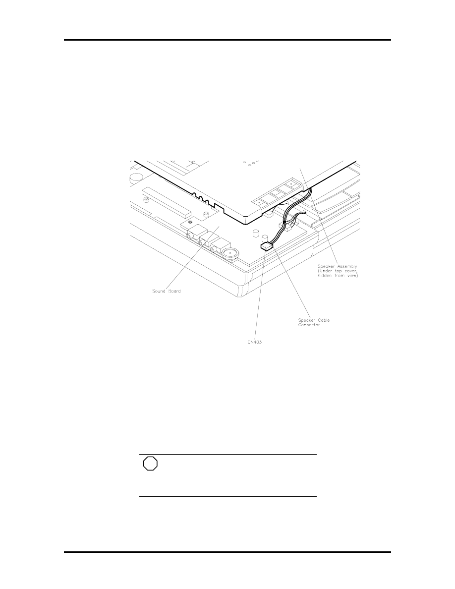
4-12 Field Service Guidelines
3.
Remove a screw from each of the outside hinge cover slots and one from the
lower left of the keyboard frame.
4.
Remove two screw covers on the back of the laptop, under each screw cover re-
move two screws.
5.
Use your hands to carefully partially separate (do not try to totally separate at this
time) the LCD and top cover from the bottom base assembly.
Figure 4-9 Removing the LCD Assembly (Step 2)
6.
Disconnect the Speaker Assembly cable from connector (CN403)
7.
Disconnect the two LCD cables
8.
It is now OK to totally separate the LCD and cover from the chassis assembly.
NOTE
If you choose to close the LCD screen at
this point, use caution to not damage the
subassembly.
SOLD BY laptopia2005 DO NOT RESELL!!
SOLD BY laptopia2005 DO NOT RESELL!!
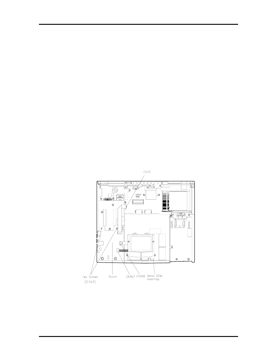
Field Service Guidelines 4-13
At this point the following components maybe removed from the unit independently.
Sound Board
VersaGlide
LED Status Board
IR board
The Sound Board must be removed to disassemble the computer further (i.e. CD-ROM
Reader, Bridge Battery, FDD/HDD Connector Board, Diskette Drive, Power Board and
Main Board).
VersaGlide Assembly
Remove the, VersaGlide, as follows
1.
Remove the prior assembly as previously described.
2.
Locate the cables that are attached to the sound board at connector CN407 and
CN406 disconnect both cables.
Figure 4-10 Disconnecting the VersaGlide Cables
SOLD BY laptopia2005 DO NOT RESELL!!
SOLD BY laptopia2005 DO NOT RESELL!!

4-14 Field Service Guidelines
3.
Remove the VersaGlide by inserting a flat head screwdriver into the openings lo-
cated at each rear corner.
Press down on the retaining tabs and slide the VersaGlide forward as far a
possible
hold the switch on the front of the VersaGlide in position when removing
VersaGlide.
lift up on the back edge of the VersaGlide and now move towards the rear
and remove.
Sound Board
Remove the Sound Board as follows:
Locate the sound board. The sound board rests right above the battery bay.
Disconnect the ribbon cable from CN405 on the Sound Board and if the
VersaGlide cables are connected to CN406 and CN407, disconnect at this
time.
Remove the two screws at the back edge of the sound board .
Lift the Sound Board to remove.
LED Status Board and IR Board
Remove the LED Statue Board and IR Board as follows:
Disconnect cable at CN20 on the Main Board.
Each of these boards are attached by two screws, remove screws
lift off the LED status board
for the IR board gently spread the LED bracket and the base assembly
apart at the IR board, slide the IR Board to the right and out.
10X CD-ROM Reader and Heat Shield
Remove the CD-ROM reader as follows:
1.
Perform all of the disassembly procedures described in this section, removing the
Keyboard, and LCD subassembly.
NOTE
It is not necessary to remove the
VersaGlide, LED Status Board or IR Board to
gain access to the CD-ROM Reader.
SOLD BY laptopia2005 DO NOT RESELL!!
SOLD BY laptopia2005 DO NOT RESELL!!
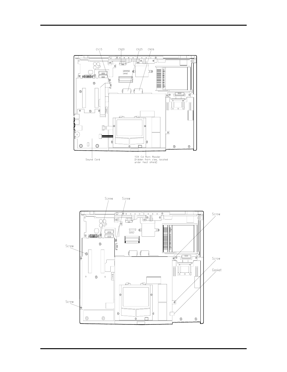
Field Service Guidelines 4-15
2.
Disconnect the following cables at connectors CN15, CN25 and CN26.
Figure 4-11 Removing the CD-ROM Reader
2.
Remove six screws securing the CD-ROM and heat shield.
Figure 4-12 Removing the CD-ROM Reader Assembly Screws
SOLD BY laptopia2005 DO NOT RESELL!!
SOLD BY laptopia2005 DO NOT RESELL!!

4-16 Field Service Guidelines
3.
Remove the gasket.
4.
Remove the CD-ROM and heat shield by lifting straight up from the assembly.
5.
To remove the CD-ROM from the heat shield, do the following.
turn the CD-ROM and heat shield assembly so the bottom of the CD-ROM is
facing up with the door pointing towards you.
remove three screws on the left side and two on the right of the CD-ROM.
removing the CD-ROM reader by sliding it out of the heat shield.
Bridge Battery and Diskette and Hard Drive Connector Board
Remove the Bridge Battery or Connector Board as follows:
1.
Remove the following as previously described:
Keyboard
Heat Sink
LCD Assembly
CD-ROM Reader and Heat Shield
2.
Remove the Bridge Battery as follows.
Remove the four screw at the front of the black insulator sheet
Lift the black insulator sheet up at the left front corner and at the same time
slide the insulator sheet out and way from the front left corner of the FDD
and HDD assembly. Fold back the insulator sheet.
Locate the cable on the Bridge Battery.
Disconnect the cable for Bridge Battery from connector on the Main Board.
Remove the Bridge Battery from the base unit.
SOLD BY laptopia2005 DO NOT RESELL!!
SOLD BY laptopia2005 DO NOT RESELL!!
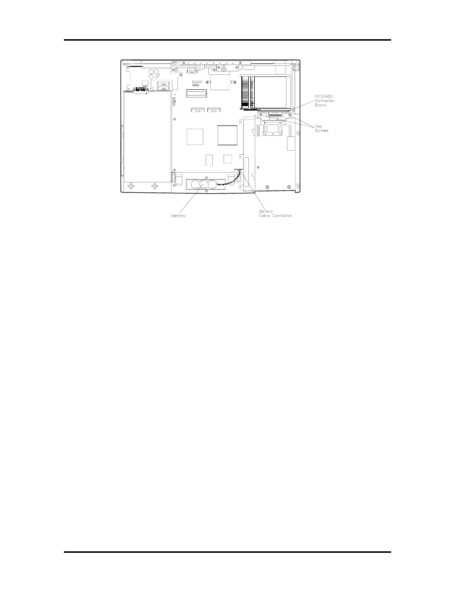
Field Service Guidelines 4-17
Figure 4-13 Removing the Bridge Battery and FDD/HDD Connector Board
3.
To remove the FDD/HDD connector board,
remove two screws followed by the retaining bracket
remove two stand offs
disengage the FDD/HDD board from the Main board.
Diskette Drive
Remove the Diskette Drive as follows.
Remove the two stand offs
Disconnect the ribbon cable at connector CN19 on the Main Board
Remove four screws (two from each side of the battery bay housing and
diskette assembly)
Remove and save the tape (die cut) that covers the bottom jointing edge of
the hard drive bay and the chassis assembly
Lift the Diskette Drive out of the chassis assembly
Remove the Diskette Drive from the assembly by removing four screws
SOLD BY laptopia2005 DO NOT RESELL!!
SOLD BY laptopia2005 DO NOT RESELL!!

4-18 Field Service Guidelines
Power Board
Remove the Power Board as follows.
1.
Remove one screw and one stand off.
2.
Lift up on the Battery connector. This disconnects the power board from the main
board.
3.
Slide the board towards the front of the laptop to release the power board from
the Main board.
Main Board
The final disassembly step is to remove five stand offs and four screws and lift the main
board from the chassis case.
Reassembly
Reassembly is the reverse of the disassembly process. When reassembling use only the
proper screws and stand offs in their appropriate locations. Make sure that all connectors
are properly connected and don’t over tighten when replacing screws.
ILLUSTRATED PARTS BREAKDOWN
The next section contains the NEC part numbers and illustrated parts breakdown (IPB) fig-
ure for the NEC Versa. Figure 4-14 shows the system exploded view diagram, or IPB. Ta-
ble 4-2 lists field-replaceable parts and corresponding part numbers.
Review the entire exploded diagram to see how each part is connected or assembled. Try to
sub-divide the entire diagram paying particular attention to the LCD Assembly, Top Unit
Cover Assembly, and the Base Unit Assembly.
SOLD BY laptopia2005 DO NOT RESELL!!
SOLD BY laptopia2005 DO NOT RESELL!!
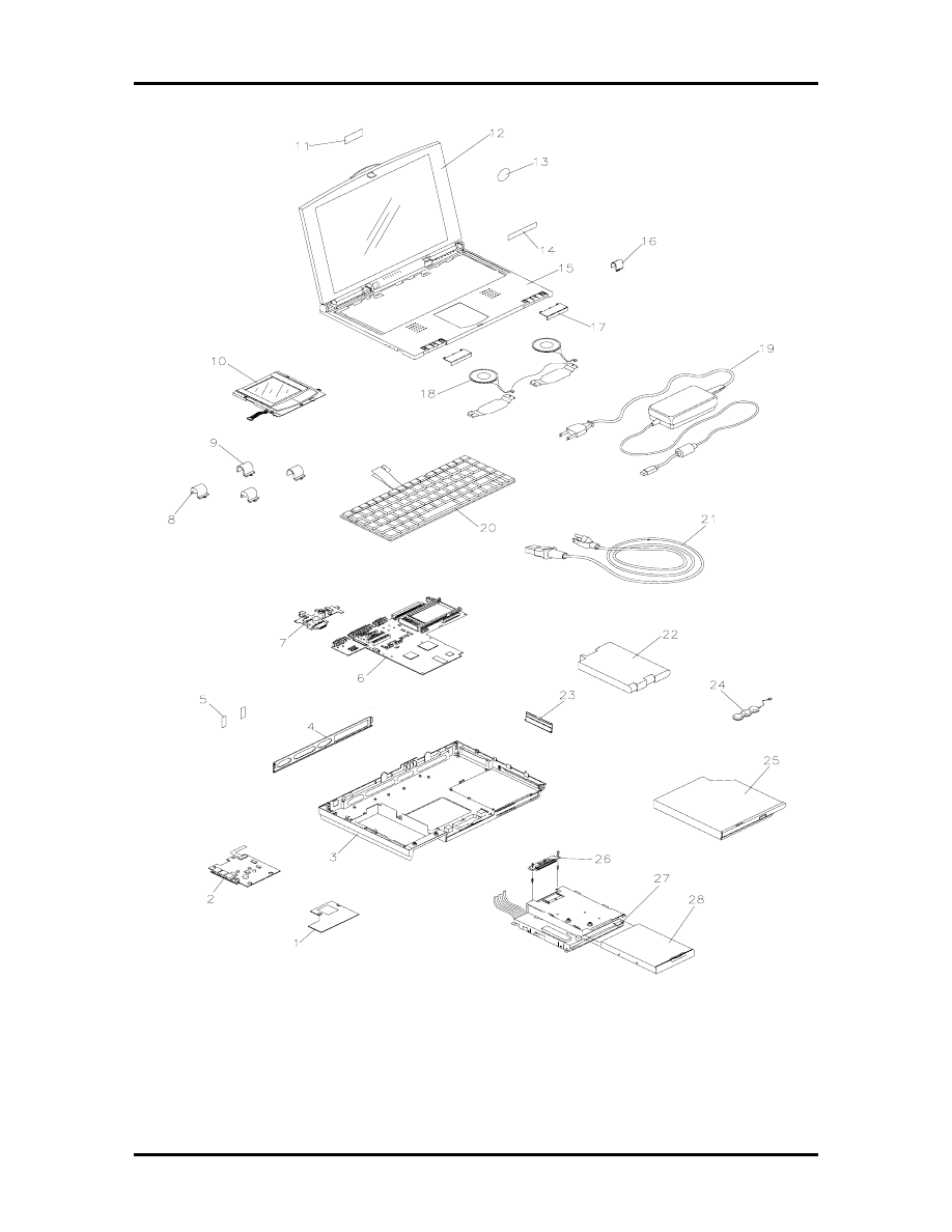
Field Service Guidelines 4-19
Figure 4-14 NEC Versa 2600 Series Illustrated Parts Breakdown
Models 2630CD (PC-6600-41703), 2635CD (PC-6610-41703),
2650CD (PC-6620-41803), 2655CD (PC-6630-41803), 2650CDT (PC-6620-91803),
& 2655CDT (PC-6630-91803)
SOLD BY laptopia2005 DO NOT RESELL!!
SOLD BY laptopia2005 DO NOT RESELL!!
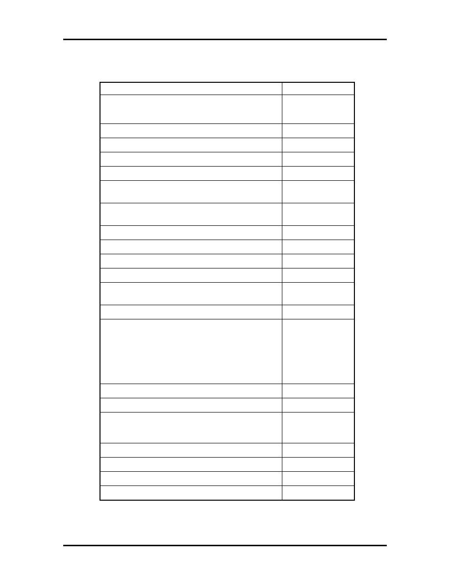
4-20 Field Service Guidelines
Table 4-2 NEC Versa 2600 Series Field-Replaceable Parts
(Models 2630CD, 2635CD, 2650CD, 2655CD, 2650CDT & 2655CDT)
Item Part Number
1. CPU Board 133MHz Assembly
150MHz Assembly
3RE0B13512240
3RE0B13512850
2. Audio Board Assembly (Sound Board) 3RE0B13512260
3. Bottom Lid Assembly 3RE0123503160
4. Back Lid Assembly(I/O Port Cover) 3RE0124500101
5. Rear Screw Covers (2 per unit) 3RE2234503811
6. Main Board Assembly DSTCV
TFT
3RE0B13512220D
3RE0B13513060B
7. Battery Charger Board Assembly (133 MHz)
(150 MHz)
3RE0B13512270
3RE0B13512870
8. LCD Hinge Covers Left (2 per unit) 3RE2234503920
9. LCD Hinge Covers right (2 per unit) 3RE2234503930
10. VersaGlide Assembly 3RE0B13512300
11. Logo, NEC 136-600325-A
12. LCD Assembly 12.1” DSTN
12.1” TFT
3RE0194500990
3RE0194501010
13. Intel Inside Sticker 158-030621-001
14. Logo Badge Versa
2630CD
2635CD
2650CD
2650CDT
2655CD
2655CDT
158-032200-009
158-032200-010
158-032200-011
158-032200-012
158-032200-013
158-032200-014
15. Cabinet Assembly (Keyboard Top Cover) 3RE0111503960
16. Power Button 3RE2169503990
17. Top Cover Assembly Screw Covers
Left
Right
3RE2234503950
3RE2234503940
18. Speaker Assembly 3RE0A11000270
19. AC Adapter 3RE0U22600110
20. U.S. Keyboard 3RE4U27001360A
21. AC Power Cable (U.S.) 3RE4W10000030
SOLD BY laptopia2005 DO NOT RESELL!!
SOLD BY laptopia2005 DO NOT RESELL!!

Field Service Guidelines 4-21
Table 4-2 NEC Versa 2600 Series Field-Replaceable Parts
(Models 2630CD, 2635CD, 2650CD, 2655CD, 2650CDT &
2655CDT) (cont’d)
22. Main Battery (Li-Ion in 133 MHz models)
(in 150 MHz models)
3RE4D25000213
3RE4D25000270
23. PCMCIA Cover
3RE2129500881
24. CMOS/Bridge Battery 3RE4D25000140
25. CD-ROM Drive 10X
3RE0291100160
26. PW Assembly HDD Connector
3RE0B13512290
27. 3.5-inch, 1.44-MB Diskette Drive 3RE0291100150
28. Hard Disk Drive
1GB
1.44GB
158-057303-000
808-874011-512A
29 33.6 U.S. Robotics Modem*
158-057200-007
30. Assembly Status and Charger*
3RE0B13513000
31. IRDA Assembly*
3RE0B13512280
32. Lid, SIMM*
3RE2129500812
33. Shipping Carton (Brown Box)*
158-041020-000
34. Shipping Carton Litho*
158-041032-000
35.
NEC Versa 2600 User’s Guide
*
819-200227-000
36.
NEC Versa 2600 Series Service and Reference
Manual
— Models 2630CD, 2635CD, 2650CD,
2655CD, 2650CDT and 2655CDT.*
819-200231-000
* Not Shown in IPB Figure.
This data was prepared April, 1999. For an up-to-date listing of spare
parts, please call FaxFlash (888) 329-0088 (international (978) 635-
6090) and order document number 42200231.
SOLD BY laptopia2005 DO NOT RESELL!!
SOLD BY laptopia2005 DO NOT RESELL!!
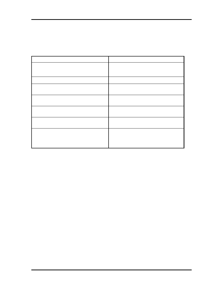
4-22 Field Service Guidelines
SERVICE INFORMATION
NEC service and information telephone numbers are listed in Table 4-3.
Table 4-3 NEC Service and Information Telephone Numbers
Service
Call
To order NECCSD spare parts
In the U.S. and Canada, call 1(800) 632-
4525
To order options in the U.S.
Local Sales Office
To access the NECCSD Electronic Bulletin
Board System (BBS)
1(978) 635-4706
To download files - provides software drivers
and the latest ROM BIOS
1(978) 635-4706
NECCSD Customer Service and Technical
Support Center
In the U.S. and Canada, call 1-800-632-
4525
NECCSD Customer Assistance Center for
extended warranties and contract information
1 (888) 632-9128
NEC FaxFlash
TM
Service — automated
service that sends the latest information
about NEC products to the fax machine 24
hours a day
In the U.S. and Canada, call 1(888) 329-
0088
Outside U.S., 1(978) 635-6090
TECHNICAL SUPPORT
NECCSD Customer Service Response Center provides an E-mail service for Internet users.
Technical questions regarding NEC products can be sent over the Internet system to the
Center. The Internet address is as follows:
tech-support@neccsd.com
If it is more convenient, questions may also be faxed to the Customer Service Response
Center. The fax number is:
(978) 635-4100
Along with the complete product name and question(s), be sure to include your name and
fax number or Internet address, so that an expert can respond to the question.
It would also help to include your telephone number in case the Customer Service Re-
sponse Center can not get their answer to you. We will reply to all questions received by
Internet or fax within one business day.
SOLD BY laptopia2005 DO NOT RESELL!!
SOLD BY laptopia2005 DO NOT RESELL!!

Field Service Guidelines 4-23
PRODUCT INFORMATION
NEC FaxFlash is an automated electronic information service used to obtain up-to-date
product application notes, installation procedures, troubleshooting tips, data sheets, techni-
cal information bulletins, price lists, and other information.
Information can be obtained from the FaxFlash service 24 hours a day, 7 days a week. Us-
ing a touch-tone telephone, call the FaxFlash number, order the desired information
through the automated attendant, and FaxFlash will automatically fax the information.
Catalogs that list the documents and the document numbers are available. Current catalogs
include:
Catalog 1 – Telephone Directory and information about Online Services
Catalog 3 – Product specifications, warranty policy, UltraCare guidelines, and
sales information
Catalog 5 – Pro Serva and Express 5800 Server System technical support infor-
mation
Catalog 6 – NEC Ready Systems technical support information
Catalog 7 – Powermate Systems technical support information
Catalog 8 – NEC Portable System (including Versa Notebooks and MobilePro
Handheld Personal computers) technical support information
ORDERING INFORMATION FROM FAXFLASH
Order information from FaxFlash as follows:
1.
Check that the fax machine is on.
2.
Locate the document part number.
3.
Using a touch-tone telephone, call 1-888-329-0088 (U.S. and Canada only).
For international use, enter the international long distance access number, the
U.S. telephone number, and the U.S. extension (1-978-635-6090).
4.
Listen to the instructions provided by the automated attendant.
Press
1
to skip the FaxFlash introduction and jump to the automated instructions
for ordering a document or catalog.
Press
2
for an introduction to FaxFlash, followed by the automated instructions
for ordering a document or catalog.
5.
When asked by the automated attendant, enter your fax number and telephone
number.
SOLD BY laptopia2005 DO NOT RESELL!!
SOLD BY laptopia2005 DO NOT RESELL!!

4-24 Field Service Guidelines
For international use, first enter the international long distance access number
(011), your country code, area code or city code, then your fax number.
The information requested will be sent automatically to your fax machine. If FaxFlash at-
tempts to send the second order before the first order is completed, the order could be can-
celed. After three tries, FaxFlash assumes that the line is busy.
SOLD BY laptopia2005 DO NOT RESELL!!
SOLD BY laptopia2005 DO NOT RESELL!!
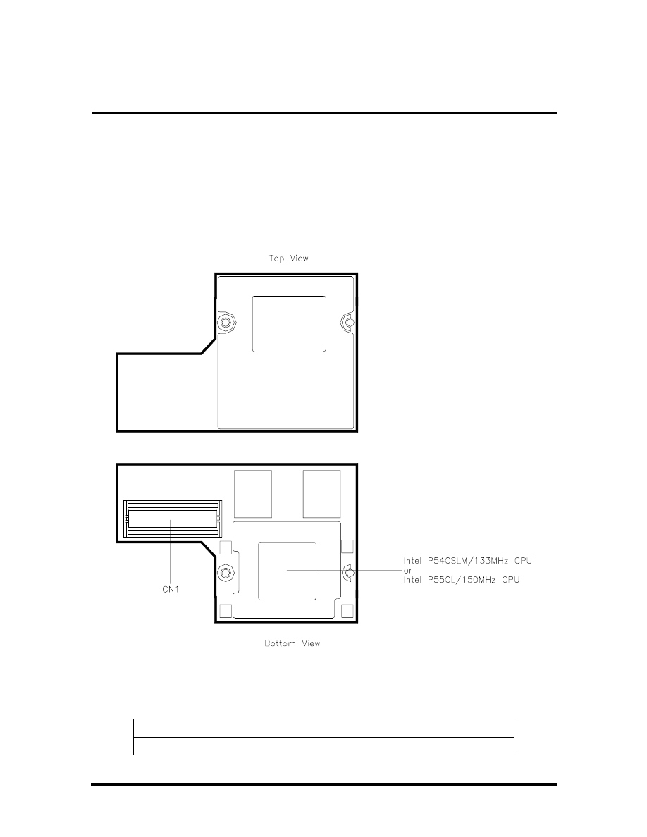
Appendix A
Connector Locations and
Pin Assignments
Figure A-1 and Table A-1 show CPU board connectors. The remaining tables provide pin
assignments for additional system connectors.
Figure A-1 CPU Board Layout
Table A-1 CPU Board Connector
Connector
Description
CN1
Main Board Connector
SOLD BY laptopia2005 DO NOT RESELL!!
SOLD BY laptopia2005 DO NOT RESELL!!
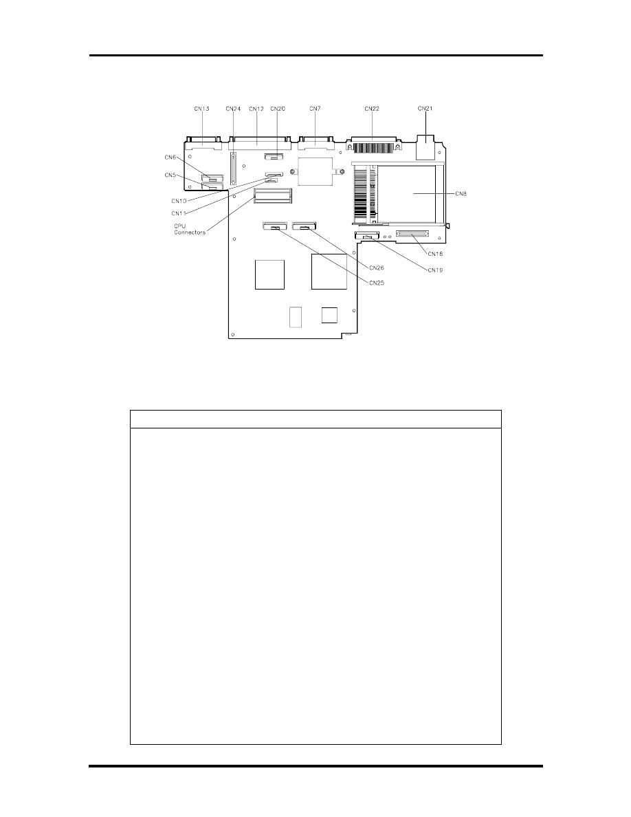
A-2 Connector Locations and Pin Assignments
Figure A-2 Main Board Layout
Table A-2 Main Board Connectors
Connector
Description
CN5
LCD Connector
CN6
LCD Connector
CN7
Monitor Connector
CN8
PC Card Connector
CN10
Keyboard Connector
CN11
Keyboard Connector
CN12
Parallel Connector
CN13
Serial Connector
CN18
HDD Connector
CN19
FDD Connector
CN20
LED Status Board Connector
CN21
Keyboard/Mouse Connectors
CN22
Expansion Connector
CN24
DC to DC Converter Board Connector
CN25
CD-ROM Connector
CN26
CD-ROM Connector
SOLD BY laptopia2005 DO NOT RESELL!!
SOLD BY laptopia2005 DO NOT RESELL!!
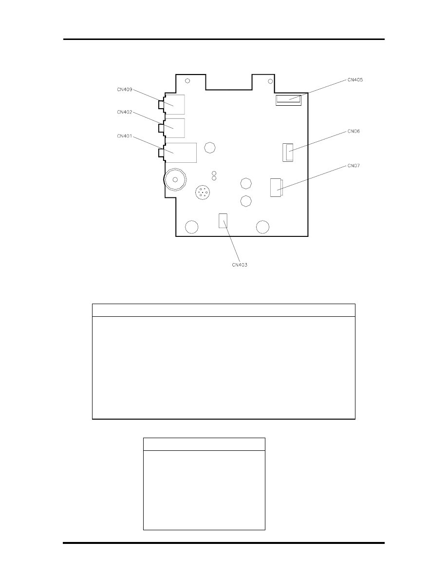
Connector Locations and Pin Assignments A-3
Figure A-3 Sound Board Layout
Table A-3 Sound Board Connectors
Connector
Description
CN409
Line In Connector
CN402
Microphone Connector
CN401
Headphone Connector
CN405
Main Board Connector
CN406
VersaGlide Connector
CN407
VersaGlide Connector
CN403
Speaker Connector
Table
A-4
Keyboard/Mouse
Connectors
Pin
Signal
1
Keyboard Data
2
Mouse Data
3
Ground
4
+5V
5
Keyboard Clock
6
Mouse Clock
SOLD BY laptopia2005 DO NOT RESELL!!
SOLD BY laptopia2005 DO NOT RESELL!!
A-4 Connector Locations and Pin Assignments
Table A-5 Serial Port Connector Pin Assignments
Pin
Signal
1
Data Carrier
2
Receive Data
3
Transmit Data
4
Data Terminal Ready
5
Ground
6
Data Set Ready
7
Request to Send
8
Clear to Send
9
Ring Indicator
Table A-6 CRT Connector Pin Assignments
Pin
Signal
1
Red
2
Green
3
Blue
4
OPT1
5
Ground
6
Ground
7
Ground
8
Ground
9
+5V PnP VESA Vcc
10
Ground
11
OPT2
12
PnP VESA Data
13
Horizontal Sync
14
Vertical Sync
15
PnP VESA Clock
SOLD BY laptopia2005 DO NOT RESELL!!
SOLD BY laptopia2005 DO NOT RESELL!!
Connector Locations and Pin Assignments A-5
Table A-7 Parallel Printer Pin Assignments
Pin
Signal
1
- Strobe
2
Data Bit 0
3
Data Bit 1
4
Data Bit 2
5
Data Bit 3
6
Data Bit 4
7
Data Bit 5
8
Data Bit 6
9
Data Bit 7
10
- Acknowledge
11
Busy
12
PE
13
Select
14
- Auto Feed XT
15
- Error
16
- Initialize
17
- Select In
18 -25
Ground
Table
A-8
Power
Connector
Pin
Signal
1
Ground
2
DCSYS
3
DCCHG
4
Type
SOLD BY laptopia2005 DO NOT RESELL!!
SOLD BY laptopia2005 DO NOT RESELL!!

A-6 Connector Locations and Pin Assignments
Table A-9 Hard Disk Drive Connector
Pin
Signal
1
HDD Access LED
2
+5V
3
Chip Select 0
4
+5
5
Chip Select 1
6
+5V
7
Address 0
8
+5V
9
Address 2
10
+5V
11
Address 1
12
+5V
13
Diagnostic
14
Not Used
15
IRQ
16
Not Used
17
Not Used
18
IO Channel Ready
19
MS Select
20
IO Write
21
I/O Read
22
Not Used
23
Data 0
24
Data1
25
Data15
26
Data14
27
Data2
28
Data13
29
Data3
30
Not Used
31
Data12
32
Ground
SOLD BY laptopia2005 DO NOT RESELL!!
SOLD BY laptopia2005 DO NOT RESELL!!

Connector Locations and Pin Assignments A-7
Table A-9 Hard Disk Drive Connector
Pin
Signal
33
Data4
34
Ground
35
Data4
36
Ground
37
Data5
38
Ground
39
Data10
40
Ground
41
Data6
42
Ground
43
Data9
44
Ground
45
Data7
46
Not Used
47
Ground
48
Ground
49
RESET
50
Ground
SOLD BY laptopia2005 DO NOT RESELL!!
SOLD BY laptopia2005 DO NOT RESELL!!

Index
A
AC adapter, 2-4
AC power port, 1-9
Active mode, 1-21, 2-25
Automatic power saving features, 1-20
B
Backup system disk, 4-2
Battery charging time, 2-9
Battery life, 2-8
Battery pack, 1-9
handling, 2-6
precautions, 2-9
replacing, 2-7, 4-5
when to change, 2-7
Battery status, 2-5
Battery warning, 2-6
BIOS update, 1-17
Bridge battery, 1-13
C
Cable connections, 2-3
Cache RAM, 1-14
CD-ROM Reader, 1-6, 1-10
Chip types, 1-16
Cleaning
internal components, 4-2
outer surface, 4-2
CPU, 1-16
CPU board, 1-11
CPU board connectors, A-1
Creative Vibra 16S VLSI chip, 1-18
CRT connector pin assignments, A-4
D
Disassembly guidelines, 4-4
Diskette drive, 1-6, 1-10
Display, 1-24
E
Entering setup, 2-17
Expansion port, 1-8
Extending battery life, 2-8
F
Field-replaceable parts list, 4-18
Flash ROM, 1-17
Function keys, 2-13
H
Handling battery packs, 4-3
Hard disk drive, 1-10
specifications, 1-10
Hard disk drive connector pin assignments,
A-7
Hardware failures, 2-15
Hardware Overview
VersaBay II, 1-6
Headphones, 1-7
I
I/O board, 1-13
I/O connector descriptions, 2-3
Increasing system memory, 1-14
Infrared port, 2-3
Internal batteries, 2-10
Interrupt level assignments, 1-19
IR port, 1-8
K
Kensington lock, 1-7
Keyboard, 1-5, 1-24
Keyboard controller, 1-18
Keyboard panel controls, 2-11
Keyboard port, 1-8
Keyboard/mouse connectors, A-4
L
LCD, 1-2
LCD features, 1-3
LCD types, 1-3
Line-In, 1-7
Local power management, 1-21
Low battery power, 2-5
SOLD BY laptopia2005 DO NOT RESELL!!
SOLD BY laptopia2005 DO NOT RESELL!!

Index-2
M
Maintaining LCD quality, 4-3
Memory
cache RAM, 1-14
Memory map, 1-14
Microphone, 1-7
Microprocessor, 1-16
Model configurations, 1-1
Monitor port, 1-8
Mouse port, 1-8
N
NEC Versa disassembly sequence, 4-4
NEC Versa video modes, B-1
O
Operating controls, 2-11
Ordering information from FastFacts, 4-23
P
Parallel interface enhanced capabilities
port, 1-15
Parallel port, 1-8
Parallel port pin assignments, A-5
Password, 2-22
PC card slots, 1-7
Plug and play, 1-21
Post error messages, 2-15
Post errors, 2-15
Power
good battery life, 2-23
good system performance, 2-24
maximum battery life, 2-23
maximum system performance, 2-24
PCMCIA, 2-24
user setting AC, 2-24
user setting battery, 2-24
Power button, 1-4
Power connector pin assignments, A-5
Power LED, 1-4, 2-12
Power Management
Active mode, 2-25
default settings, 2-26
How to use, 2-25
power saving modes, 2-25
Standby mode, 2-25
Suspend mode, 2-25
Power management modes
active, 1-21
local standby, 1-21
suspend, 1-21
Power management overview, 1-20
Power sources, 2-4
Power switch, 2-11
Power-on self test (POST), 2-14
Product information, 4-23
Q
Quick troubleshooting, 3-1
R
Replacing the battery pack, 2-7, 4-5
ROM BIOS, 1-17
S
Security, 2-22
Serial interface, 1-16
Serial port, 1-9
Serial port connector pin assignments, A-4
Service telephone numbers, 4-22
Servicing a hard disk, 4-2
Servicing the system
required tools, 4-5
Setting a password, 2-22
Setting system parameters, 2-19
Boot Device, 2-21
Components, 2-22
Date and Time, 2-21
power, 2-23
Setting time and date, 2-21
Setup key functions, 2-18
Setup utility, 2-16
Side panel controls, 2-11
Sound board, 1-12
Standby mode, 1-21
Status bar, 2-12
Status LEDs, 1-4
Suspend mode, 2-25
System disassembly
bridge battery, 4-16
SOLD BY laptopia2005 DO NOT RESELL!!
SOLD BY laptopia2005 DO NOT RESELL!!

Index-3
LCD and top cover, 4-11
System icons, 2-12
System paPOPrameters, 2-14
System parameters, 2-19
System setup, 2-1
System specifications, 1-22
System status
icons, 2-12
System video, 1-15
T
Technical support, 4-22
Troubleshooting
helpful questions, 3-4
U
Unpacking, 2-1
Updating the BIOS, 2-13
V
VersaGlide, 1-5
VGA controller, 1-17
Video mode
CRT only, 1-15
Video RAM, 1-15
Volume control, 1-7
Y
Y-cable adapter, 1-8
SOLD BY laptopia2005 DO NOT RESELL!!
SOLD BY laptopia2005 DO NOT RESELL!!
BATTERY REPLACEMENT
A lithium CMOS clock battery in your computer maintains system configuration information. In the event
that the battery fails to maintain system configuration information, NEC recommends that you replace the
battery. Have an authorized NEC service representative replace the battery.
!
WARNING
There is a danger of explosion if the battery is incorrectly replaced. Replace only with the same or
equivalent type recommended by the manufacturer. Discard used batteries according to the
manufacturer’s instructions.
!
ATTENTION
Il y a danger d’explosion s’il y a replacement incorrect de la batterie. Remplacer uniquement avec une bat-
terie du même type ou d’un type recommandé par le constructeur. Mettre au rébut les batteries usagées
conformément aux instructions du fabricant.
BATTERY DISPOSAL
The bridge battery is made of nickel metal hydride (NiMH). The main battery and CMOS battery are made
of lithium-ion (Li-Ion).
Contact your local waste management officials for other information regarding the environmentally sound
collection, recycling, and disposal of the batteries. For additional information on the proper collection or
disposal of rechargeable batteries, please call 1-800-8-BATTERY.
SOLD BY laptopia2005 DO NOT RESELL!!
SOLD BY laptopia2005 DO NOT RESELL!!
(For United States Use Only)
FEDERAL COMMUNICATIONS COMMISSION
RADIO FREQUENCY INTERFERENCE STATEMENT
!
WARNING
Changes or modifications to this unit not expressly approved by the party responsible for
compliance could void the user’s authority to operate the equipment.
NOTE
This is a Class B Digital Device.
This equipment has been tested and found to comply
with the limits for a Class B digital device, pursuant to Part 15 of the FCC Rules. These limits
are designed to provide reasonable protection against harmful interference in a residential
installation. This equipment generates, uses and can radiate radio frequency energy and, if not
installed and used in accordance with the instructions, may cause harmful interference to radio
communications.
However, there is no guarantee that interference will not occur in a particular installation. If this
equipment does cause harmful interference to radio or television reception, which can be determined by
turning the equipment off and on, the user is encouraged to try to correct the interference by one or
more of the following measures.
Reorient or relocate the receiving antenna.
Increase the separation between the equipment and receiver.
Connect the equipment to an outlet on a circuit different from the one to which the receiver is
connected.
To meet FCC standards, shielded cables and power cords are required to connect this device to a
personal computer or other Class B certified device.
Canadian Department of Communications Compliance Statement
This equipment does not exceed the Class B limits for radio noise emissions from digital apparatus set out in the Radio interference
Regulations of the Canadian Department of Communications.
Avis de conformité aux normes du ministère des Communications du Canada
Cet appareil respecte les limites de bruits radioélectriques applicables aux appareils numériques de Classe B prescrites dans le Règlement sur
le brouillage radioélectrique édicté par le ministère des Communications du Canada.
European Community Directive Conformance Statement
This product is in conformity with the protection requirements of EC Council Directive 89/336/EEC on the approximation of laws of the
Member States relating to electro-magnetic compatibility. This product satisfied the Class B limits of EN 55022.
NEC Computer Systems Division, Packard Bell NEC, Inc.
1414 Massachusetts Avenue
Boxborough, Massachusetts 01719
1-800-632-4525
SOLD BY laptopia2005 DO NOT RESELL!!
SOLD BY laptopia2005 DO NOT RESELL!!
Document Outline
- PROPRIETARY NOTICE
- Contents
- Preface
- Technical Information
- Setup and Operation
- Troubleshooting
- Field Service Guidelines
- ILLUSTRATED PARTS BREAKDOWN
- Appendix A
- Index
- BATTERY REPLACEMENT
- FCC Statement
Wyszukiwarka
Podobne podstrony:
Service Manual NEC Versa 2400 Series Laptop
Service Manual NEC Versa 6050 Series Laptop
Service Manual NEC Versa 2000 Series Laptop
Service Manual NEC Versa 6000 Series Laptop
Nec Versa LXI Owners Manual
hplj 5p 6p service manual vhnlwmi5rxab6ao6bivsrdhllvztpnnomgxi2ma vhnlwmi5rxab6ao6bivsrdhllvztpnnomg
Oberheim Prommer Service Manual
Korg SQ 10 Service Manual
MAC1500 service manual
Kyocera Universal Feeder UF 1 Service Manual
Proview RA783 LCD Service Manual
indesit witp82euy Service Manual
Glow Worm installation and service manual Hideaway 70CF UIS
Proview PZ456 LCD Service Manual
Glow Worm installation and service manual Ultimate 50CF UIS
ewm2000 service manual
więcej podobnych podstron