
Working Instruction, Mechanical
1219-0627 Rev 1
1(30)
Working Instruction, Mechanical
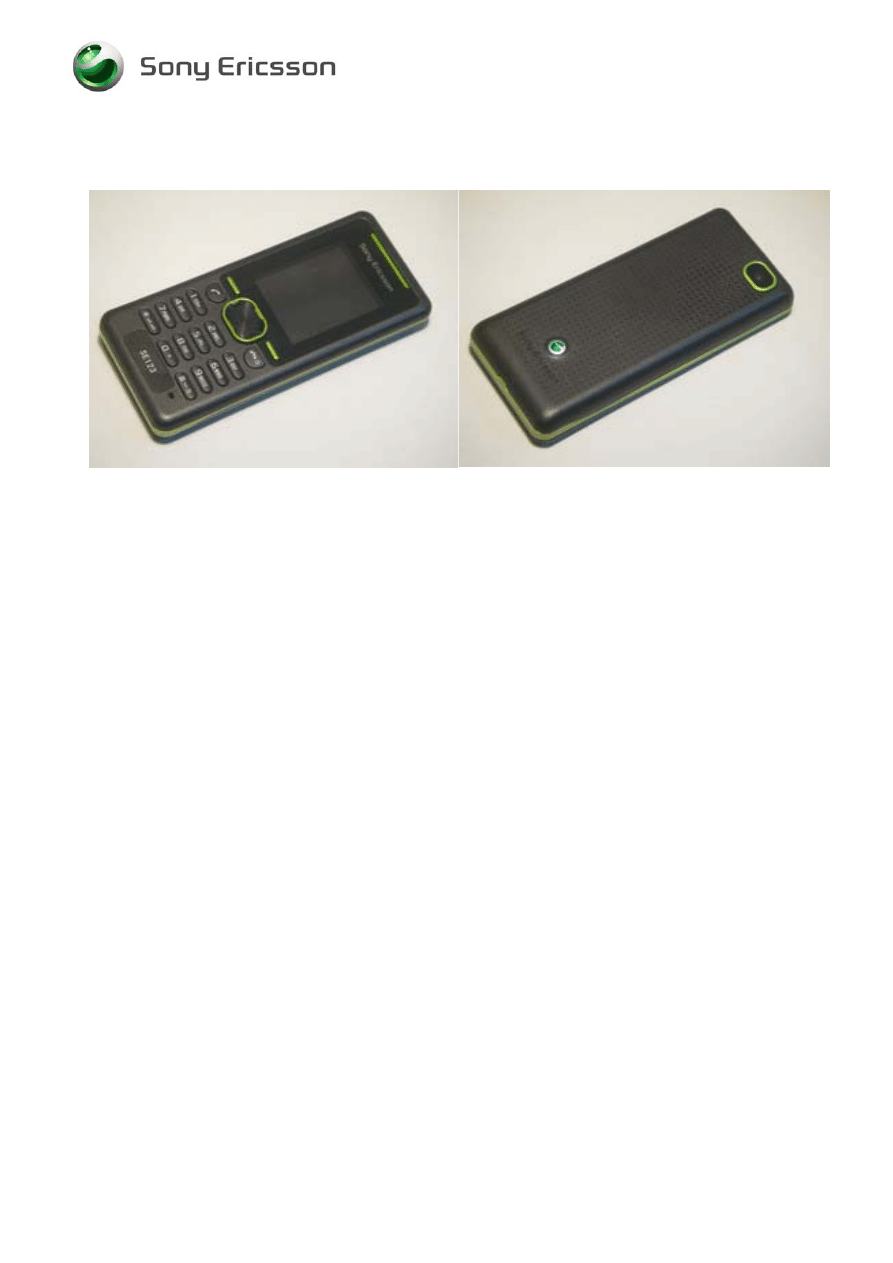
Applicable for K330
CONTENTS
Introduction .............................................................................. 2
Equipment................................................................................. 3
General cautions ...................................................................... 4
Adhesives ................................................................................. 4
Disassembly ............................................................................. 5
Overview ................................................................................... 5
Battery Cover & Battery......................................................... 6
Front Cover & Keypad........................................................... 7
Rear Cover Assy and PCB Unit............................................. 9
Display ................................................................................ 11
Replacements......................................................................... 13
Battery Cover..........................................................................14
Front Cover .............................................................................14
Keypad ....................................................................................14
Rear Cover Assy.....................................................................14
Display 1.7'' TFT .....................................................................14
Vibrator....................................................................................15
Loudspeaker 16mm Circular .................................................16
System Connector and Sponge ............................................17
Antenna Assembly .................................................................18
Bluetooth Antenna .................................................................18
Camera VGA CMOS................................................................19
Liquid Intrusion Indicator ......................................................20
Keyboard PCB Assembly ......................................................21
KRH - label ..............................................................................22
Reassembly ............................................................................ 23
Overview .................................................................................23
Display ................................................................................ 24
PCB Unit and Rear Cover Assy........................................... 26
Keypad and Front Cover ..................................................... 27
Battery and Battery Cover ................................................... 29
Revision history ..................................................................... 30
Company Internal
©
Sony Ericsson Mobile Communications AB
Working Instruction, Mechanical
1219-0627 Rev 1
2(30)
1 Introduction
Company Internal
©
Sony Ericsson Mobile Communications AB
Working Instruction, Mechanical
1219-0627 Rev 1
3(30)
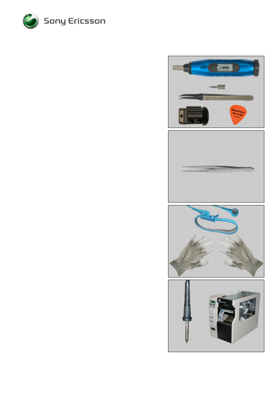
1.1 Equipment
SPECIAL TOOLS
Special tools can be found in the tool catalogue
• Screwdriver
• Torx Bits T6
• Flex film assembly tool
• Camera Removal Tool
• Guitar Pick (Plectrum)
STANDARD TOOLS
Standard tools has to be purchased locally
• Pair of tweezers
ESD EQUIPMENT
Protect the phone from ESD damages whenever it has
been opened by using:
• ESD-wristband
• ESD-gloves
LABEL EQUIPMENT
The following special equipment is required when replacing
or installing a new label:
• Hot air flow solder station
• Zebra printer connected to computer
Company Internal
©
Sony Ericsson Mobile Communications AB

Working Instruction, Mechanical
1219-0627 Rev 1
4(30)
1.2 General cautions
The following cautions are considered to be generic for all phone models and will not be repeated in
the Disassembly, Replacements and Reassembly sections:
• S
WITCH OFF THE PHONE AND REMOVE ANY MEMORY STICK BEFORE THE START OF THE DISASSEMBLY
!
• K
EEP ALL CONTACT SURFACES CLEAN
!
• B
E CAREFUL WHEN USING TOOLS LIKE THE DENTIST HOOK
,
TWEEZERS
,
OPENING TOOLS
,
GUITAR PICK
ETC
.
TO AVOID SCRATCHES OR DAMAGES TO THE EXTERIOR AND INTERIOR PARTS OF THE PHONE
!
• B
E CAREFUL NOT TO DAMAGE ANY CONTACT SPRINGS
!
• R
EMEMBER TO REMOVE THE PROTECTION FOILS ON NEW PARTS SUCH AS THE FRONT COVER
AND
LCD!
• N
EVER TOUCH THE DISPLAY GLASS
!
• U
SE AIR BLOW EQUIPMENT TO KEEP THE FRONT WINDOW AND DISPLAY MODULE DUST FREE
!
1.3 Adhesives
Use a dentist hook and/or the tweezers to remove old adhesives.
Clean the surface with isopropyl alcohol before attaching new adhesives.
Company Internal
©
Sony Ericsson Mobile Communications AB
Working Instruction, Mechanical
1219-0627 Rev 1
5(30)
2 Disassembly
When you are going to replace a part being listed in Replacements, the instruction of that section
usually begins by directing you to this Disassembly section with a specification of the instructions you
have to carry out in order to disassemble the phone as far as needed before returning to
Replacements for the actual replacement.
Start
DISASSEMBLY
REASSEMBLY
Content
page
REPLACEMENTS
Done
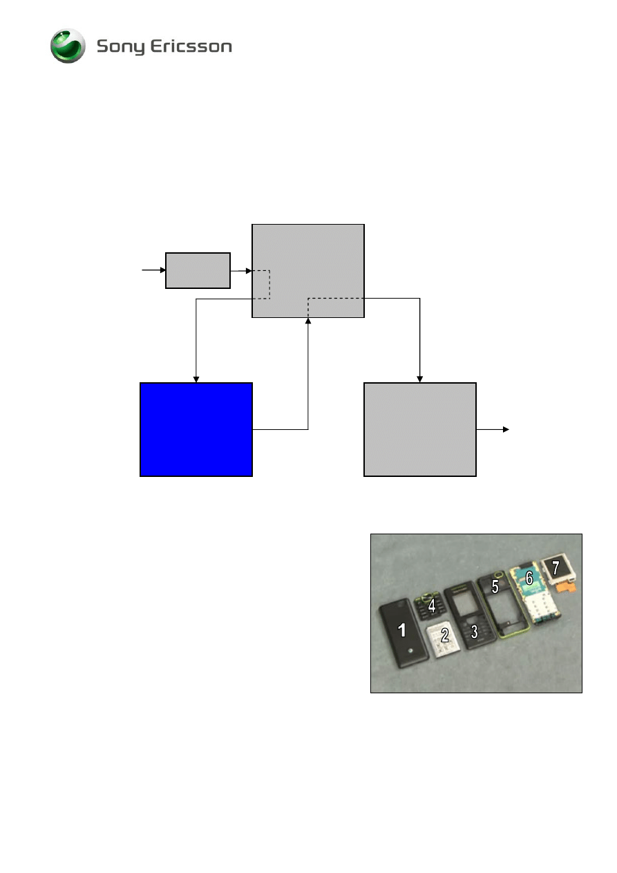
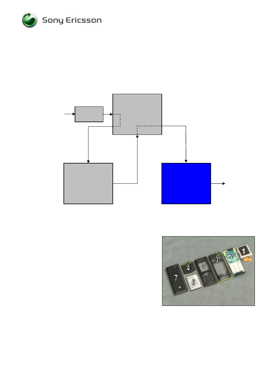
2.1 Overview
The disassembly is done in the following sequence
1. Battery
Cover
2. Battery
3. Front
Cover
4. Keypad
5. Rear
Cover
Assy
6. PCB
Unit
7. Display
Company Internal
©
Sony Ericsson Mobile Communications AB

Working Instruction, Mechanical
1219-0627 Rev 1
6(30)
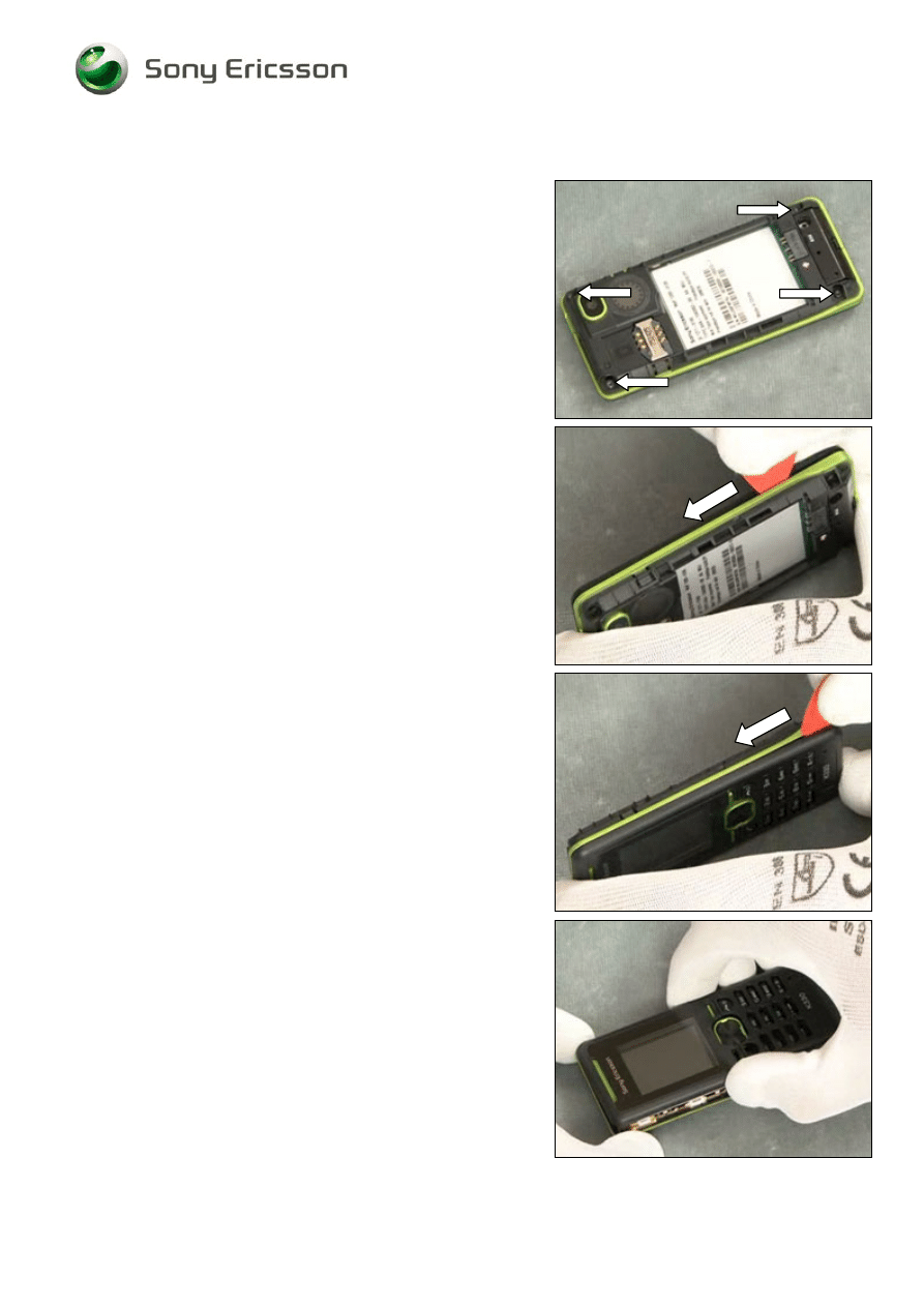
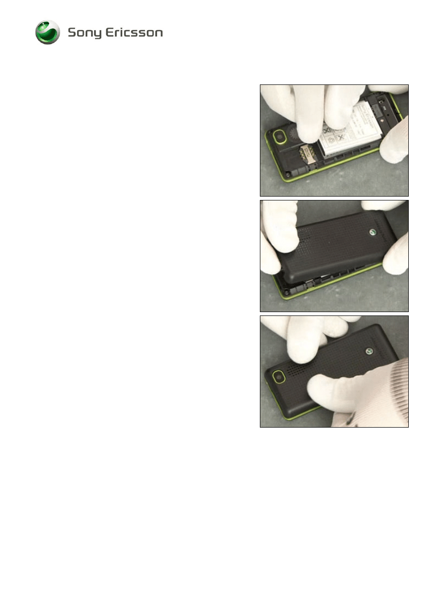
2.1.1 Battery Cover & Battery
Release the Battery Cover from the top side.
Lift up the Battery Cover
Grab and the Battery and pull it up
Company Internal
©
Sony Ericsson Mobile Communications AB
Working Instruction, Mechanical
1219-0627 Rev 1
7(30)
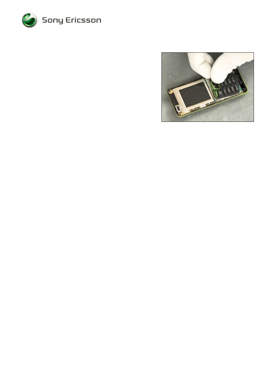
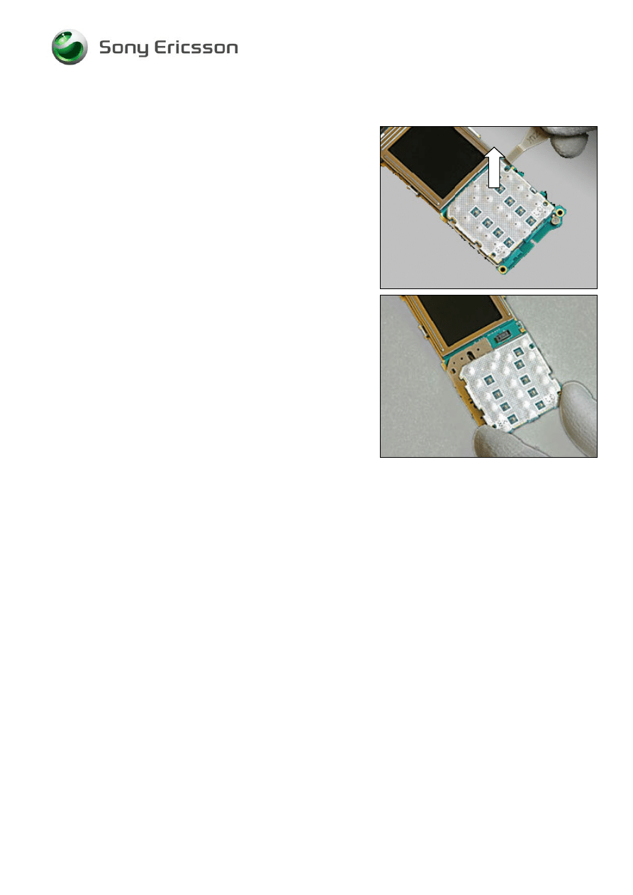
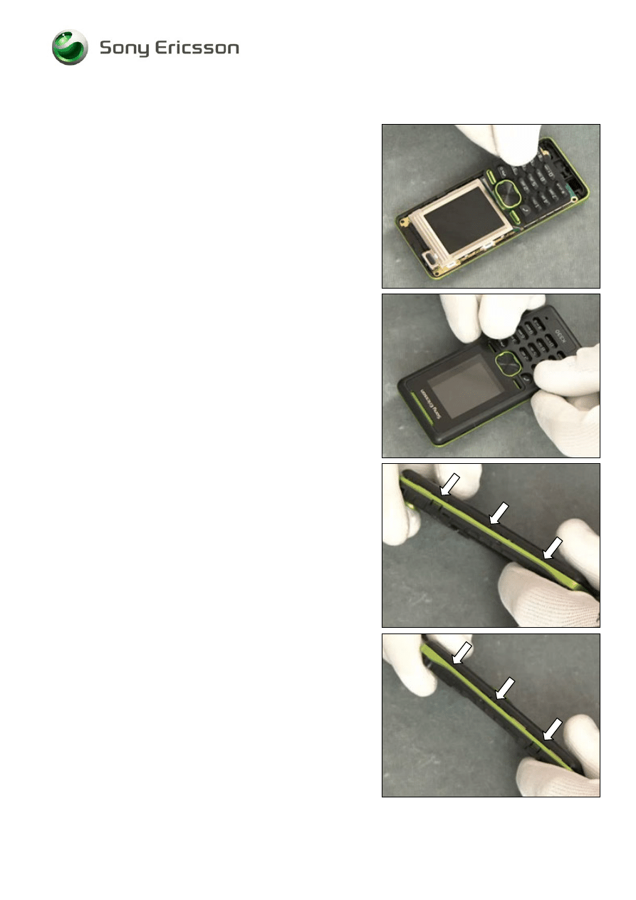
2.1.2 Front Cover & Keypad
Use Torx bit no 6 to remove the four screws
Use the Guitar pick and slide along the side
Use the Guitar pick and slide along the side
Remove the Front Cover
Company Internal
©
Sony Ericsson Mobile Communications AB
Working Instruction, Mechanical
1219-0627 Rev 1
8(30)
Front Cover and Keypad continued
Remove the Keypad
Company Internal
©
Sony Ericsson Mobile Communications AB
Working Instruction, Mechanical
1219-0627 Rev 1
9(30)
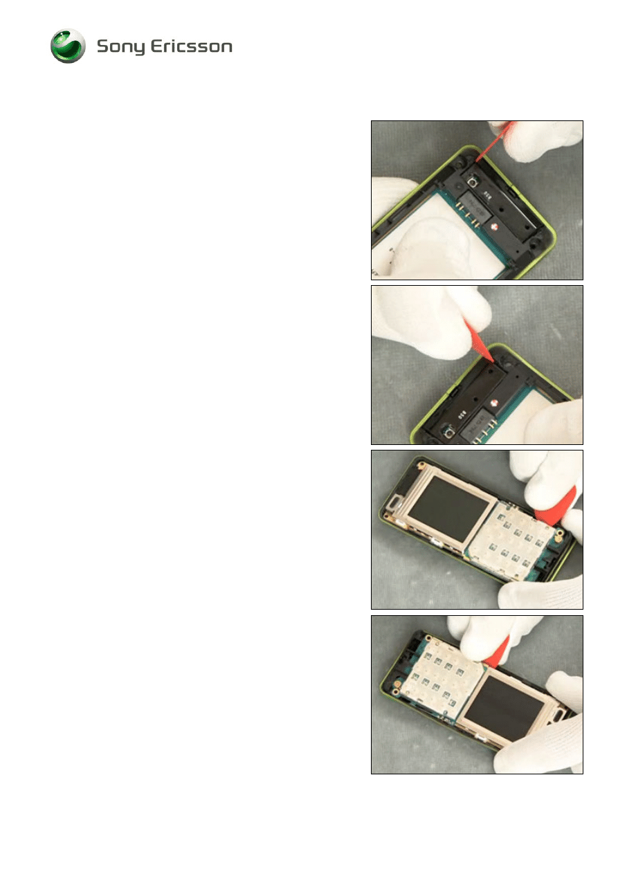
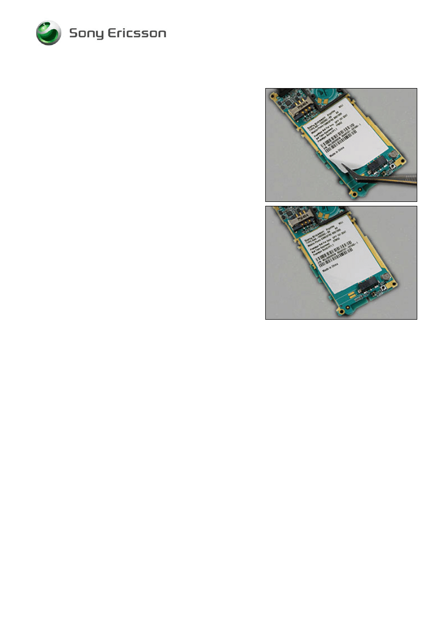
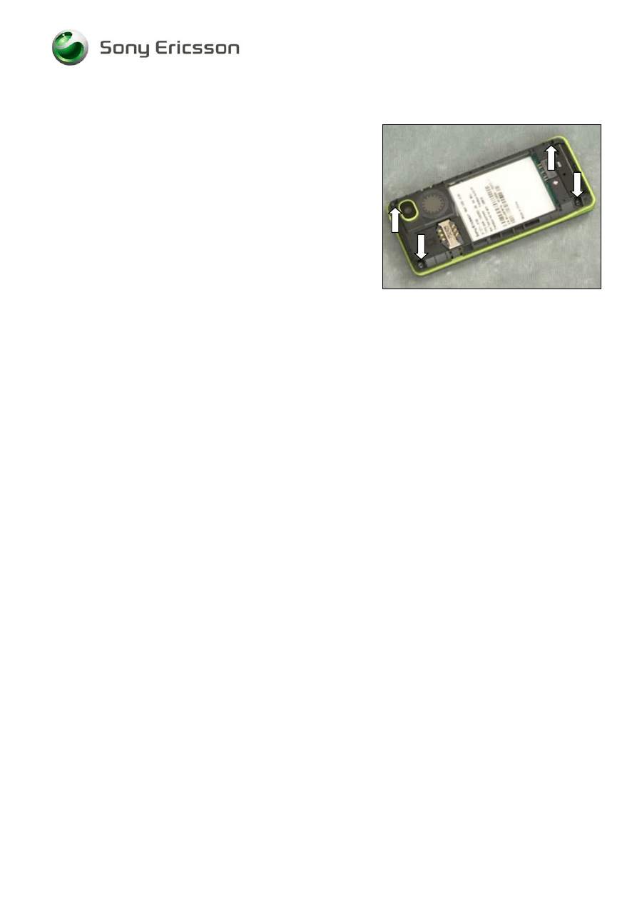
2.1.3 Rear Cover Assy and PCB Unit
Release the snap hook with a Guitar Pick
Release the snap hook with a Guitar Pick
D
O NOT TOUCH THE
D
ISPLAY
!
Use the Front Opening Tool to release the snap hooks
Use the Front Opening Tool to release the snap hooks
Company Internal
©
Sony Ericsson Mobile Communications AB
Working Instruction, Mechanical
1219-0627 Rev 1
10(30)
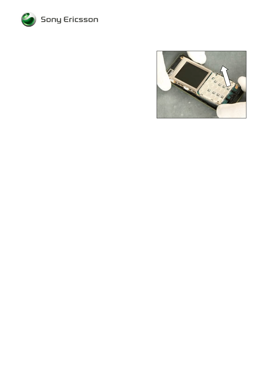
Rear Cover Assy and PCB Unit continued
Pull up the PCB Unit from the bottom side and remove it.
Company Internal
©
Sony Ericsson Mobile Communications AB
Working Instruction, Mechanical
1219-0627 Rev 1
11(30)
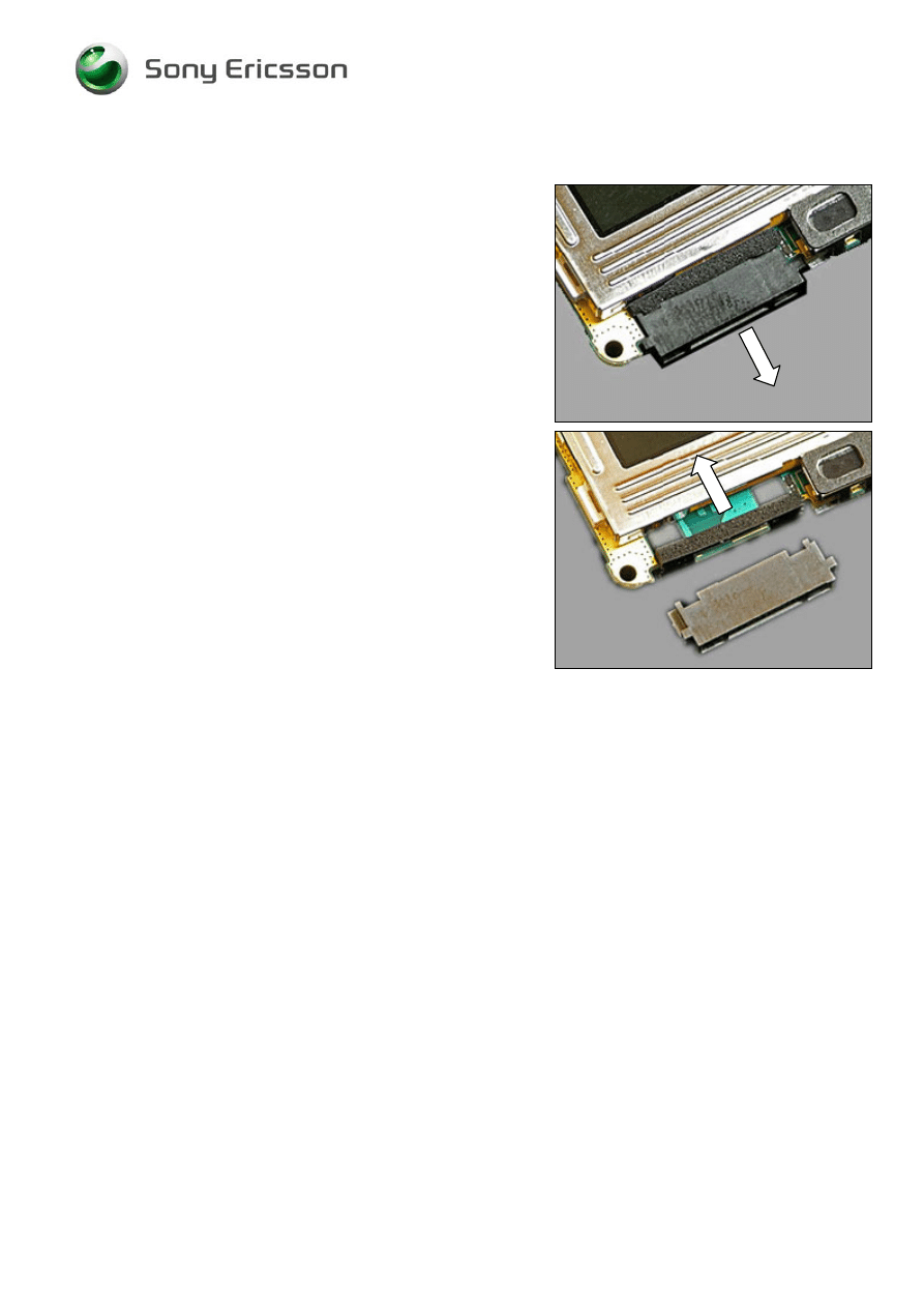
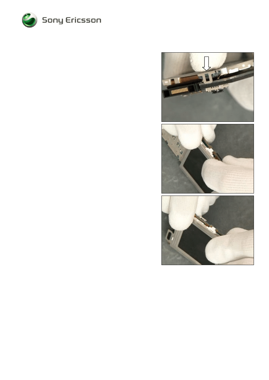
2.1.4 Display
Use a Guitar Pick to release the snap hook
Use a Guitar Pick to release the opposite snap hook.
Push the Display carefully from the snap hook
Display released
Company Internal
©
Sony Ericsson Mobile Communications AB
Working Instruction, Mechanical
1219-0627 Rev 1
12(30)
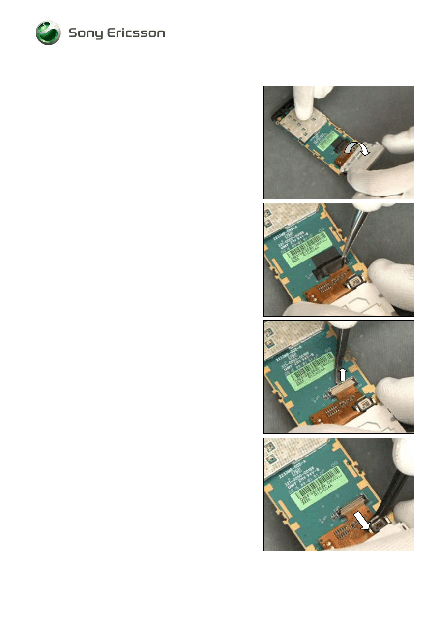
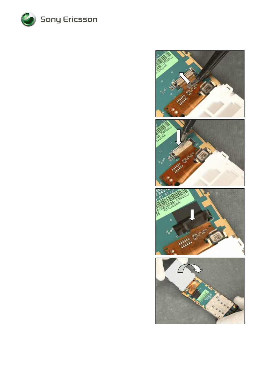
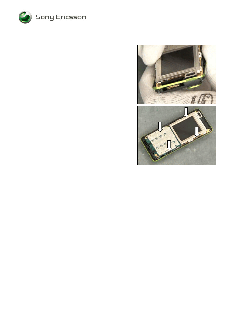
Display continued
Turn over the Display
Remove the isolation tape
Open the FPC Connector
Pull out the flex film and remove the Display
Company Internal
©
Sony Ericsson Mobile Communications AB
Working Instruction, Mechanical
1219-0627 Rev 1
13(30)
3 Replacements
Search for the part to be replaced on the Contents page and go to that instruction to be found in this
Replacements section.
The instruction usually begins by directing you to the Disassembly section with a specification of the
instructions you have to carry out in order to disassemble the phone as far as needed before the
actual replacement.
Go back to this Replacements section and carry out the instruction.
The instruction usually ends by directing you to the Reassembly section with a specification of the
instructions you have to carry out in order to reassemble the phone.
Start
DISASSEMBLY
REASSEMBLY
Contents
page
REPLACEMENTS
Done
Company Internal
©
Sony Ericsson Mobile Communications AB

Working Instruction, Mechanical
1219-0627 Rev 1
14(30)
3.1 Battery
Cover
Follow the 2.1.1 Disassembly instructions!
Prepare the new Battery Cover.
Follow the 4.1.4 Reassembly instructions!
3.2 Front
Cover
Follow the 2.1.1 – 2.1.2 Disassembly instructions!
Prepare the new Front Cover
Follow the 4.1.3 – 4.1.4 Reassembly instructions!
3.3 Keypad
Follow the 2.1.1 – 2.1.2 Disassembly instructions!
Prepare the new Keypad
Follow the 4.1.3 – 4.1.4 Reassembly instructions!
3.4 Rear
Cover
Assy
Follow the 2.1.1 – 2.1.3 Disassembly instructions!
Prepare a new Rear Cover Assy
Follow the 4.1.2 – 4.1.4 Reassembly instructions!
3.5 Display
1.7''
TFT
Follow the 2.1.1 – 2.1.4 Disassembly instructions!
Prepare a new Display 1.7'' TFT
Follow the 4.1.1– 4.1.4 Reassembly instructions!
Company Internal
©
Sony Ericsson Mobile Communications AB
Working Instruction, Mechanical
1219-0627 Rev 1
15(30)
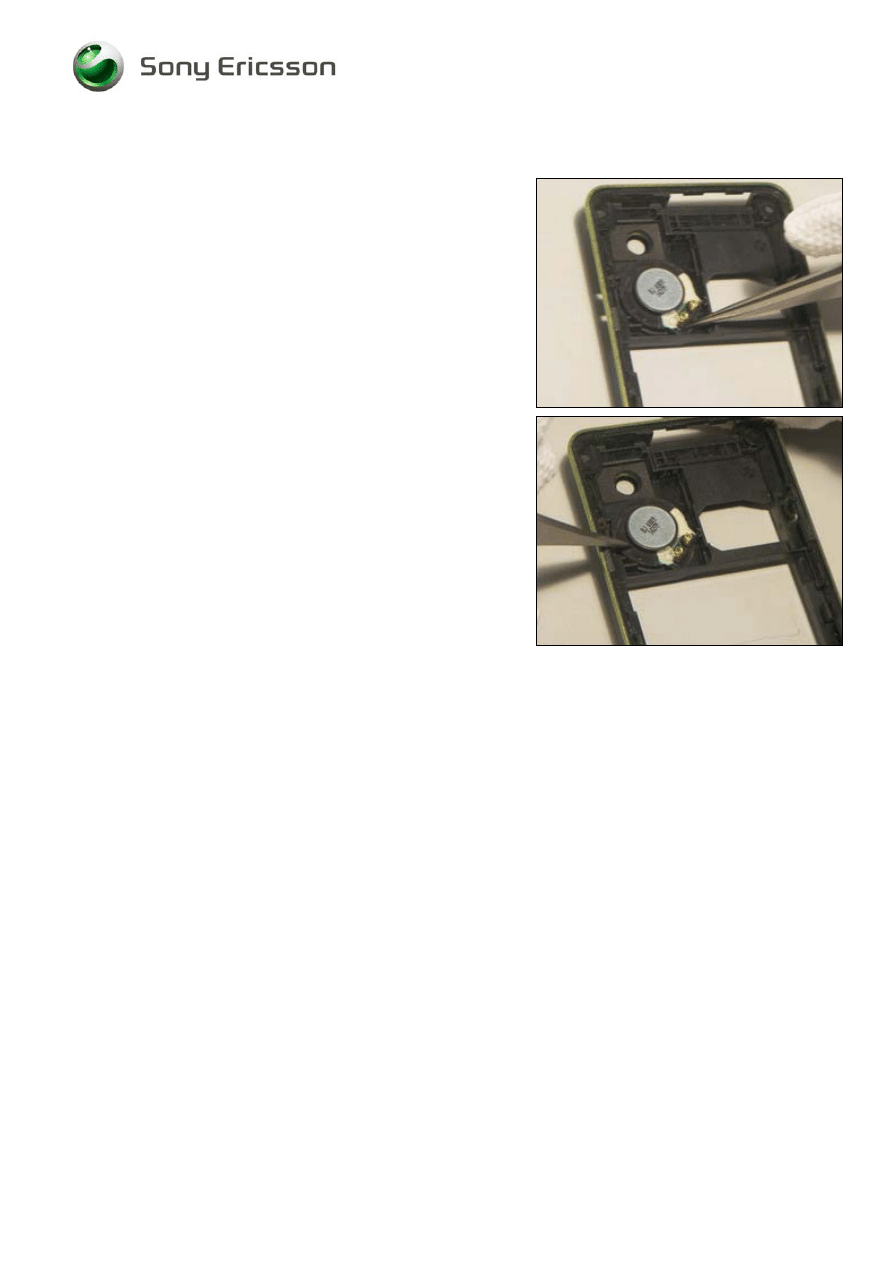
3.6 Vibrator
REMOVAL
Follow the 2.1.1 – 2.1.3 Disassembly instructions!
Use a pair of tweezers to remove the Vibrator
INSTALLATION
D
O NOT TOUCH THE
V
IBRATOR CONTACT SPRINGS OR DAMAGE
THE FLYWHEEL
.
Use a pair of tweezers to position the Vibrator.
Follow the 4.1.2– 4.1.4 Reassembly instructions!
Company Internal
©
Sony Ericsson Mobile Communications AB
Working Instruction, Mechanical
1219-0627 Rev 1
16(30)
3.7 Loudspeaker 16mm Circular
REMOVAL
Follow the 2.1.1 – 2.1.3 Disassembly instructions!
Use a pair of tweezers to remove the Loudspeaker.
Clean the Cavity with Isopropyl Alcohol
INSTALLATION
Use a pair of tweezers to position the Loudspeaker.
Press down to fasten the adhesive
Follow the 4.1.2– 4.1.4 Reassembly instructions!
Company Internal
©
Sony Ericsson Mobile Communications AB
Working Instruction, Mechanical
1219-0627 Rev 1
17(30)
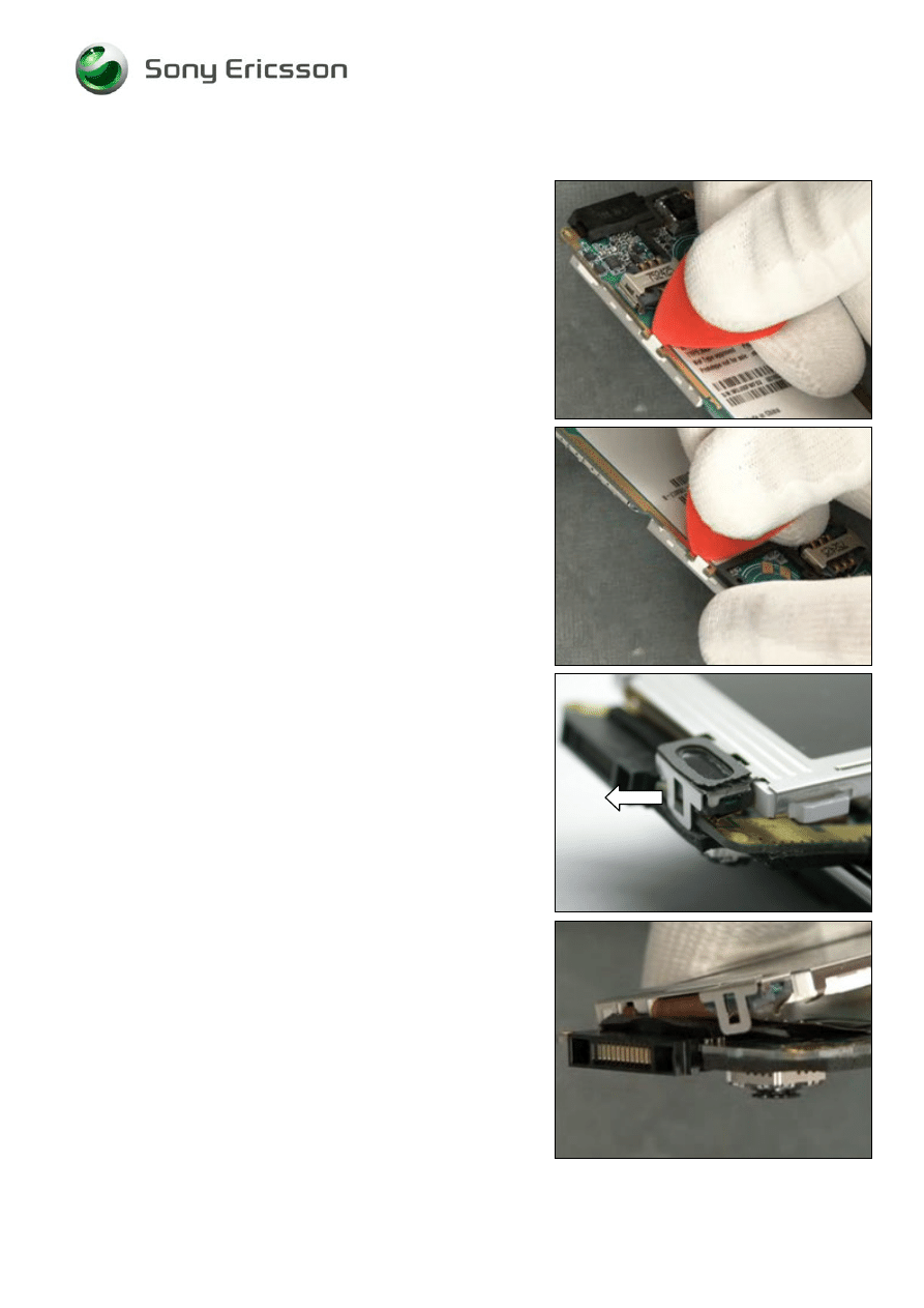
3.8 System Connector and Sponge
REMOVAL
Follow the 2.1.1 – 2.1.3 Disassembly instructions!
Use your fingers to remove the System Connector and
Sponge.
INSTALLATION
Replace the System Connector and Sponge
Follow the 4.1.2– 4.1.4 Reassembly instructions!
Company Internal
©
Sony Ericsson Mobile Communications AB
Working Instruction, Mechanical
1219-0627 Rev 1
18(30)
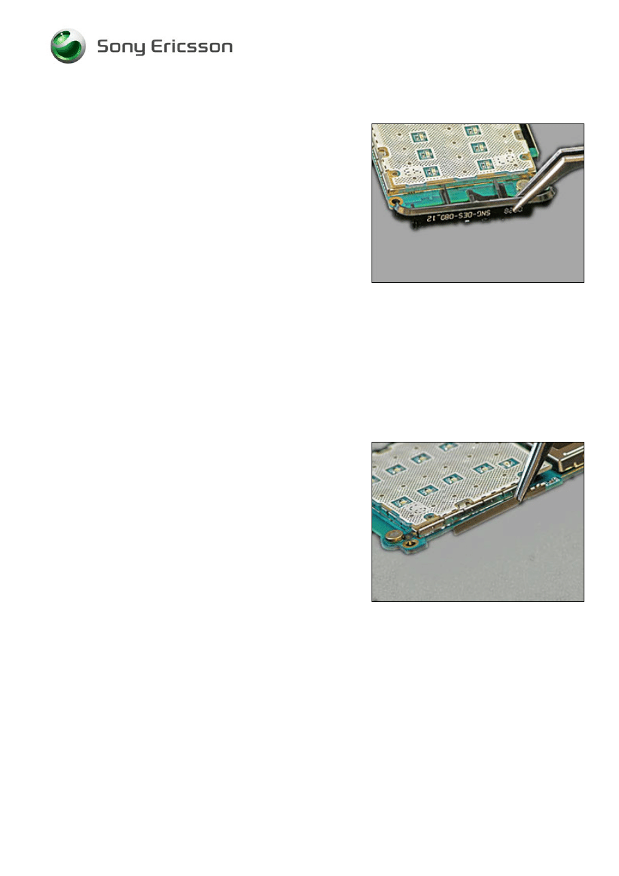
3.9 Antenna
Assembly
Follow the 2.1.1 – 2.1.3 Disassembly instructions!
Replace the Antenna Connector with a pair of tweezers.
Follow the 4.1.2– 4.1.4 Reassembly instructions!
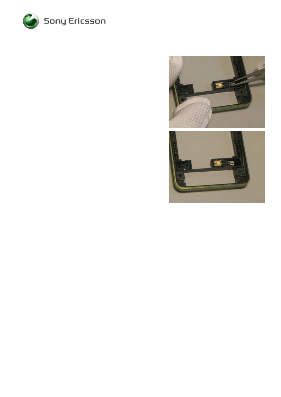
3.10 Bluetooth Antenna
Follow the 2.1.1 – 2.1.3 Disassembly instructions!
Replace the Bluetooth Antenna with a pair of tweezers.
Follow the 4.1.2– 4.1.4 Reassembly instructions!
Company Internal
©
Sony Ericsson Mobile Communications AB
Working Instruction, Mechanical
1219-0627 Rev 1
19(30)
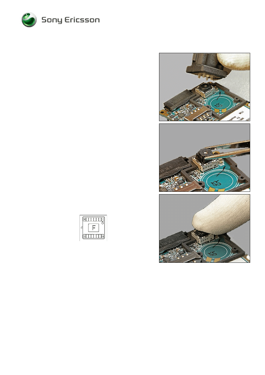
3.11 Camera VGA CMOS
REMOVAL
Follow the 2.1.1 – 2.1.3 Disassembly instructions!
Press down the Camera Removal Tool
Pull up the camera
INSTALLATION
Press gently down the Camera into the socket.
K
EYING TAP ON CAMERA
Follow the 4.1.2– 4.1.4 Reassembly instructions!
Company Internal
©
Sony Ericsson Mobile Communications AB
Working Instruction, Mechanical
1219-0627 Rev 1
20(30)
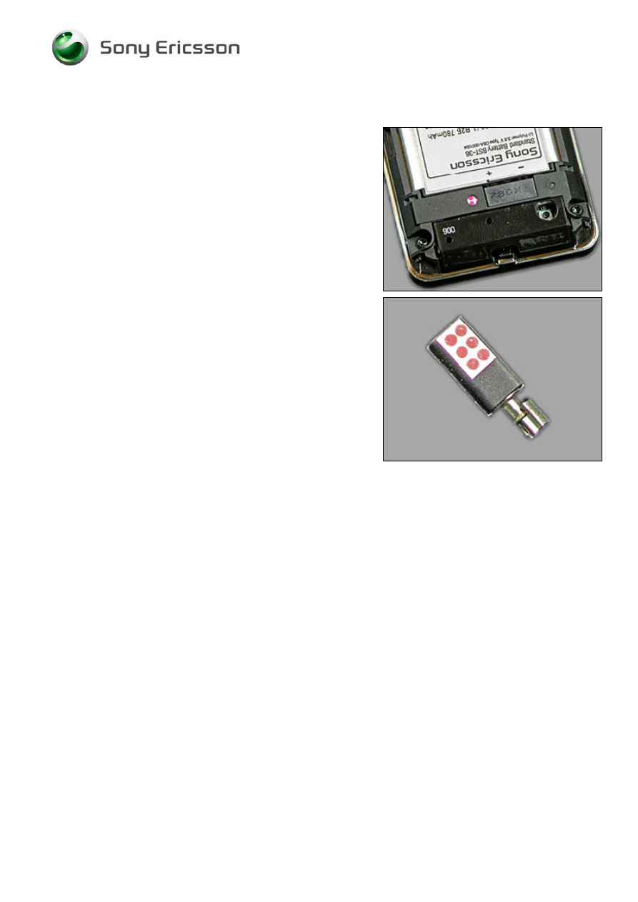
3.12 Liquid Intrusion Indicator
INSPECTION
Notice the Liquid Intrusion Indicator by removing the Battery
Cover.
Follow the 2.1.1 – 2.1.3 Disassembly instructions and
3.6 Replacement Instruction!
Replace the Liquid Intrusion Indicator with a pair of
tweezers.
Follow the 3.6 Replacement Instruction and 4.1.2– 4.1.4
Reassembly instructions!
Company Internal
©
Sony Ericsson Mobile Communications AB
Working Instruction, Mechanical
1219-0627 Rev 1
21(30)
3.13 Keyboard PCB Assembly
REMOVAL
Follow the 2.1.1 – 2.1.3 Disassembly instructions!
Remove the Keyboard PCB Assembly with a Front Opening
Tool
Clean the surface with isopropyl alcohol
INSTALLATION
Y
OU MUST USE A NEW
K
EYBOARD
PCB
A
SSEMBLY
!
Replace the Keyboard PCB Assembly
Press down to fasten the adhesive
Follow the 4.1.2– 4.1.4 Reassembly instructions!
Company Internal
©
Sony Ericsson Mobile Communications AB
Working Instruction, Mechanical
1219-0627 Rev 1
22(30)
3.14 KRH - label
Follow the 2.1.1 – 2.1.3 Disassembly instructions.
Read the old label and/or write the information into the
“Label make” program before removal.
Note the position of the label before removal.
Heat up the label by using hot air, if needed.
Carefully remove the label without causing scratches.
If there still are residues, clean the surface with isopropyl
alcohol.
Check that the proper label format is loaded in the Zebra
printer.
Write a new label by using the program “Label make” and
check that the printing is OK.
Take the new label and place it onto the frame as in the
adjacent picture.
O
NE LABEL ONLY IS ALLOWED
!
Follow the 4.1.2 – 4.1.4 Reassembly instructions.
Company Internal
©
Sony Ericsson Mobile Communications AB
Working Instruction, Mechanical
1219-0627 Rev 1
23(30)
4 Reassembly
After replacing a part being listed in Replacements, the instruction of that section usually ends by
directing you to this Reassembly section with a specification of the instructions you have to carry out
in order to reassemble the phone.
Start
DISASSEMBLY
REASSEMBLY
Contents
page
REPLACEMENTS
Done
4.1 Overview
The disassembly is done in the following sequence
1. Display
2. PCB
Unit
3. Rear
Cover
Assy
4. Keypad
5. Front
Cover
6. Battery
7. Battery
Cover
Company Internal
©
Sony Ericsson Mobile Communications AB
Working Instruction, Mechanical
1219-0627 Rev 1
24(30)
4.1.1 Display
Insert the flex film into the connector
Close the FPC Connector
N
EW TAPE MUST BE USED
!
Mount the Isolate Tape on the connector
Turn over the Display
Company Internal
©
Sony Ericsson Mobile Communications AB
Working Instruction, Mechanical
1219-0627 Rev 1
25(30)
Display continued
Press down the Earspeaker to snap it to the PCB Unit
Snap the hook to the PCB Unit
Snap the hook to the PCB Unit
Company Internal
©
Sony Ericsson Mobile Communications AB
Working Instruction, Mechanical
1219-0627 Rev 1
26(30)
4.1.2 PCB Unit and Rear Cover Assy
Mount the PCB Unit into the gap for the System Connector
D
O NOT TOUCH THE
D
ISPLAY
!
Use your finger to snap on the PCB Unit
Company Internal
©
Sony Ericsson Mobile Communications AB
Working Instruction, Mechanical
1219-0627 Rev 1
27(30)
4.1.3 Keypad and Front Cover
Position the Keypad
Use your fingers to align the Front Cover
Use your fingers to snap the Front Cover
Use your fingers to snap the Front Cover on the opposite
side
Company Internal
©
Sony Ericsson Mobile Communications AB
Working Instruction, Mechanical
1219-0627 Rev 1
28(30)
Keypad and Front Cover continued
Install new screws with a torque screwdriver at 11 Ncm with
a Torx Bits T6.
Company Internal
©
Sony Ericsson Mobile Communications AB
Working Instruction, Mechanical
1219-0627 Rev 1
29(30)
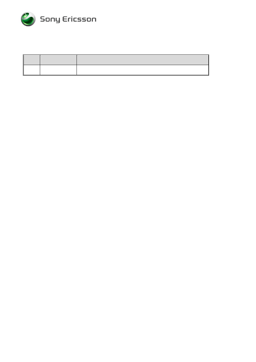
4.1.4 Battery and Battery Cover
Place the Battery
Use your fingers to align the Battery Cover
Use your fingers to snap the Battery Cover
Company Internal
©
Sony Ericsson Mobile Communications AB
Working Instruction, Mechanical
1219-0627 Rev 1
30(30)
5 Revision history
Rev.
Date
Changes / Comments
1 2008-09-25 1
st
release
Company Internal
©
Sony Ericsson Mobile Communications AB
Document Outline
- 1 Introduction
- 1
- 2 Disassembly
- 3 Replacements
- 3.1 Battery Cover
- 3.2 Front Cover
- 3.3 Keypad
- 3.4 Rear Cover Assy
- 3.5 Display 1.7'' TFT
- 3.6 Vibrator
- 3.7 Loudspeaker 16mm Circular
- 3.8 System Connector and Sponge
- 3.9 Antenna Assembly
- 3.10 Bluetooth Antenna
- 3.11 Camera VGA CMOS
- 3.12 Liquid Intrusion Indicator
- 3.13 Keyboard PCB Assembly
- 3.14 KRH - label
- 4 Reassembly
- 5 Revision history
Wyszukiwarka
Podobne podstrony:
Sony Ericsson W595 Service Manual
Sony Ericsson J100 Service Manual
sony MDS 302 sup2 service manual
Service Manual Sony TFT LCD Color Monitor CPD L133 Schematic
hplj 5p 6p service manual vhnlwmi5rxab6ao6bivsrdhllvztpnnomgxi2ma vhnlwmi5rxab6ao6bivsrdhllvztpnnomg
Oberheim Prommer Service Manual
Korg SQ 10 Service Manual
MAC1500 service manual
Sony Ericsson GC79, TELEFONIA, Opisy telefonów
Kyocera Universal Feeder UF 1 Service Manual
Proview RA783 LCD Service Manual
indesit witp82euy Service Manual
Glow Worm installation and service manual Hideaway 70CF UIS
Proview PZ456 LCD Service Manual
Glow Worm installation and service manual Ultimate 50CF UIS
ewm2000 service manual
Glow Worm installation and service manual Ultimate 60CF UIS
Proview SH770I LCD Service Manual
więcej podobnych podstron