
Working Instruction, Mechanical
3/000 21-1/FEA 209 544/114 A
Company Internal
©
Sony Ericsson Mobile Communications AB
Approved according to 1/109 41-4/FCP 119 00
30
Working Instruction, Mechanical
Applicable for J100i, J100a and J100c
CONTENTS
1
Introduction .............................................................................. 2
1.1
Equipment................................................................................. 3
1.2
General cautions ...................................................................... 4
2
Disassembly ............................................................................. 5
2.1
Overview ................................................................................... 5
2.1.1
Battery Cover & Battery......................................................... 6
2.1.2
Front Cover ........................................................................... 7
2.1.3
Keypad .................................................................................. 8
2.1.4
PBA ....................................................................................... 9
2.1.5
Antenna ass’y...................................................................... 10
3
Replacements......................................................................... 11
3.1
Battery Cover..........................................................................12
3.2
Front Cover .............................................................................12
3.3
Keypad ....................................................................................12
3.4
Antenna ass’y .........................................................................12
3.5
Rear Cover ..............................................................................12
3.6
Dome Foil ................................................................................13
3.7
System Connector..................................................................14
3.8
Earphone ass’y.......................................................................15
3.9
Loudspeaker ass’y .................................................................17
3.10
Loudspeaker Gasket ..............................................................18
3.11
Microphone .............................................................................19
3.12
Vibrator....................................................................................20
3.13
RF Cover .................................................................................21
3.14
Name Plate ..............................................................................22
3.15
Label…. ...................................................................................23
4
Reassembly ............................................................................ 24
4.1
Overview .................................................................................24
4.1.1
Antenna ass’y...................................................................... 25
4.1.2
PBA ..................................................................................... 26
4.1.3
Keypad ................................................................................ 27
4.1.4
Front Cover ......................................................................... 28
4.1.5
Battery & Battery Cover....................................................... 29
5
Revision history ..................................................................... 30
Working Instruction, Mechanical
3/000 21-1/FEA 209 544/114 A
Company Internal
©
Sony Ericsson Mobile Communications AB
2(30)
1 Introduction
J100
Working Instruction, Mechanical
3/000 21-1/FEA 209 544/114 A
Company Internal
©
Sony Ericsson Mobile Communications AB
3(30)
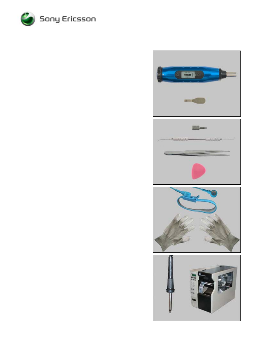
1.1 Equipment
SPECIAL TOOLS
No new special tools are introduced
• NTZ 122 459 Torque screwdriver (or equivalent)
• NTZ 112 302/2 Front opening tool
STANDARD TOOLS
Standard tools have to be locally purchased
• Torx bit no. 5
• Dentist hook
• Blunt pair of tweezers
• Guitar pick
ESD EQUIPMENT
Protect the phone from ESD damages whenever it has
been opened by using:
• ESD-wristband
• ESD-gloves
LABEL EQUIPMENT
The following special equipment is required when replacing
or installing a new label:
• Hot air flow solder station
• Zebra printer connected to computer

Working Instruction, Mechanical
3/000 21-1/FEA 209 544/114 A
Company Internal
©
Sony Ericsson Mobile Communications AB
4(30)
1.2 General
cautions
• Switch off the phone before the disassembly is begun!
• Keep all contact surfaces clean!
• Be careful when using tools like the dentist hook, tweezers, opening tools, guitar pick etc.
to avoid scratches or damages to the exterior and interior parts of the phone!
• Be careful not to damage any contact springs!
• Remember to remove the protection foils on new parts such as the front cover and the LCD!
• Never touch the display glass!
• Use air blow equipment to keep the front window and display module dust free!
Working Instruction, Mechanical
3/000 21-1/FEA 209 544/114 A
Company Internal
©
Sony Ericsson Mobile Communications AB
5(30)
2 Disassembly
When you are going to replace a part being listed in Replacements, the instruction of that section
usually begins by directing you to this Disassembly section with a specification of the instructions you
have to carry out in order to disassemble the phone as far as needed before returning to
Replacements for the actual replacement.
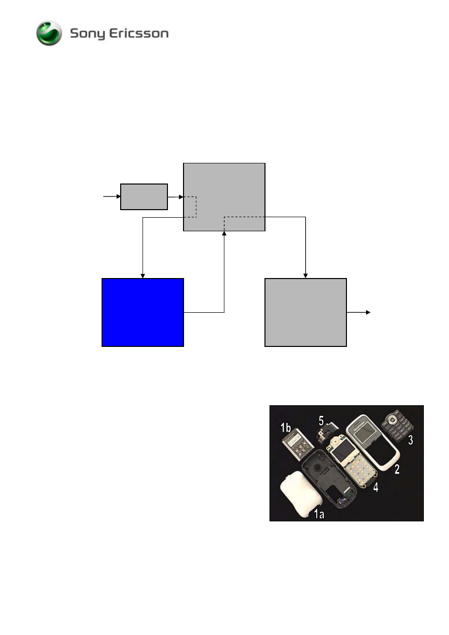
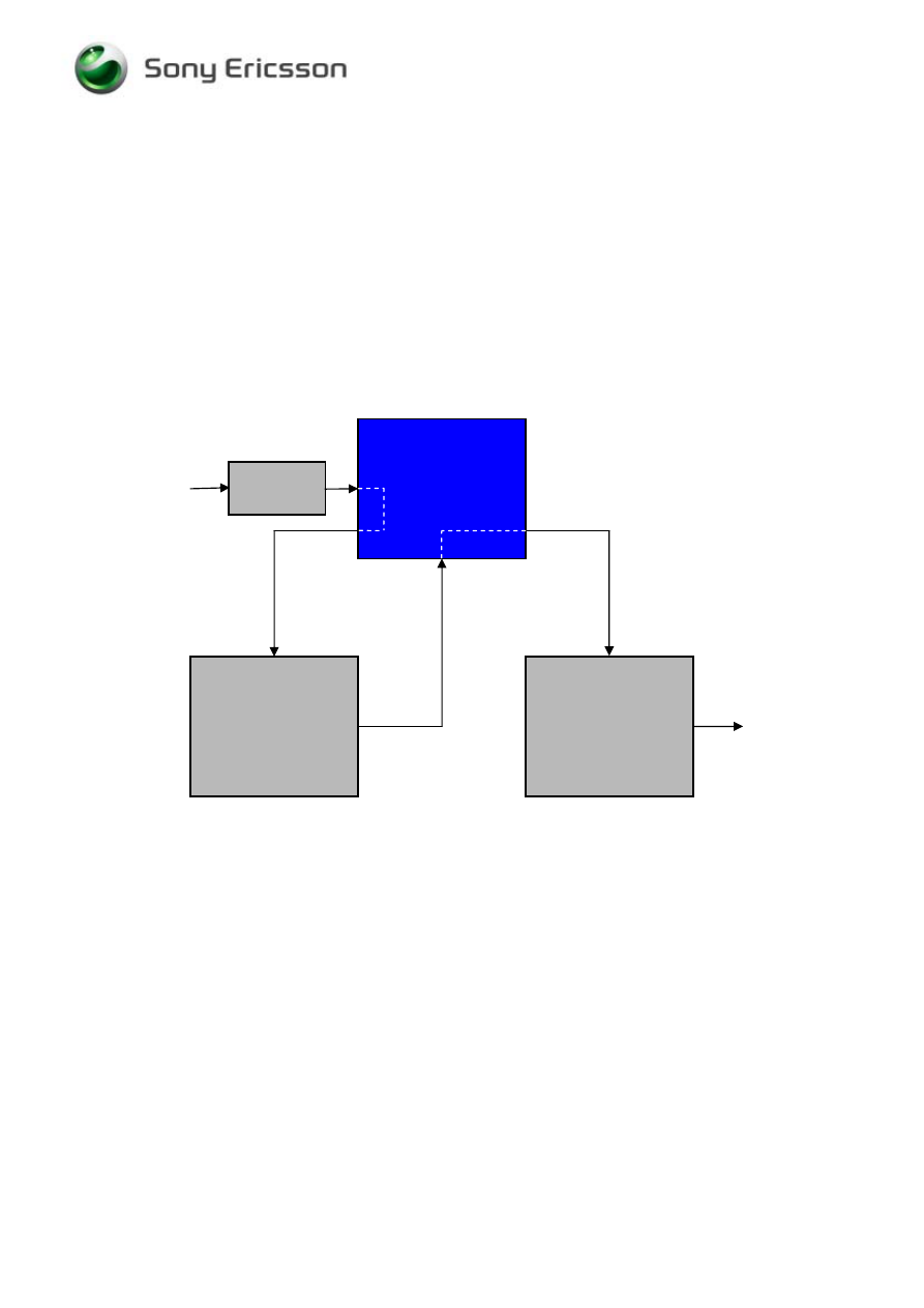
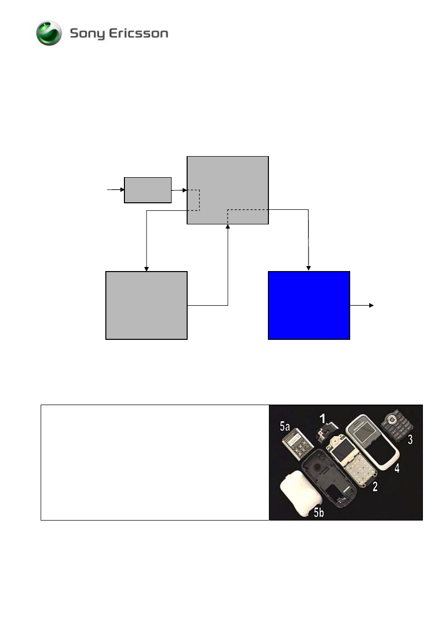
2.1 Overview
The disassembly of the phone is done in the following
sequence:
1. Battery Cover (a) and Battery (b)
2. Front Cover
3. Keypad
4. PBA
5. Antenna ass’y
Start
Done
REPLACEMENTS
DISASSEMBLY
REASSEMBLY
Contents
page
Working Instruction, Mechanical
3/000 21-1/FEA 209 544/114 A
Company Internal
©
Sony Ericsson Mobile Communications AB
6(30)
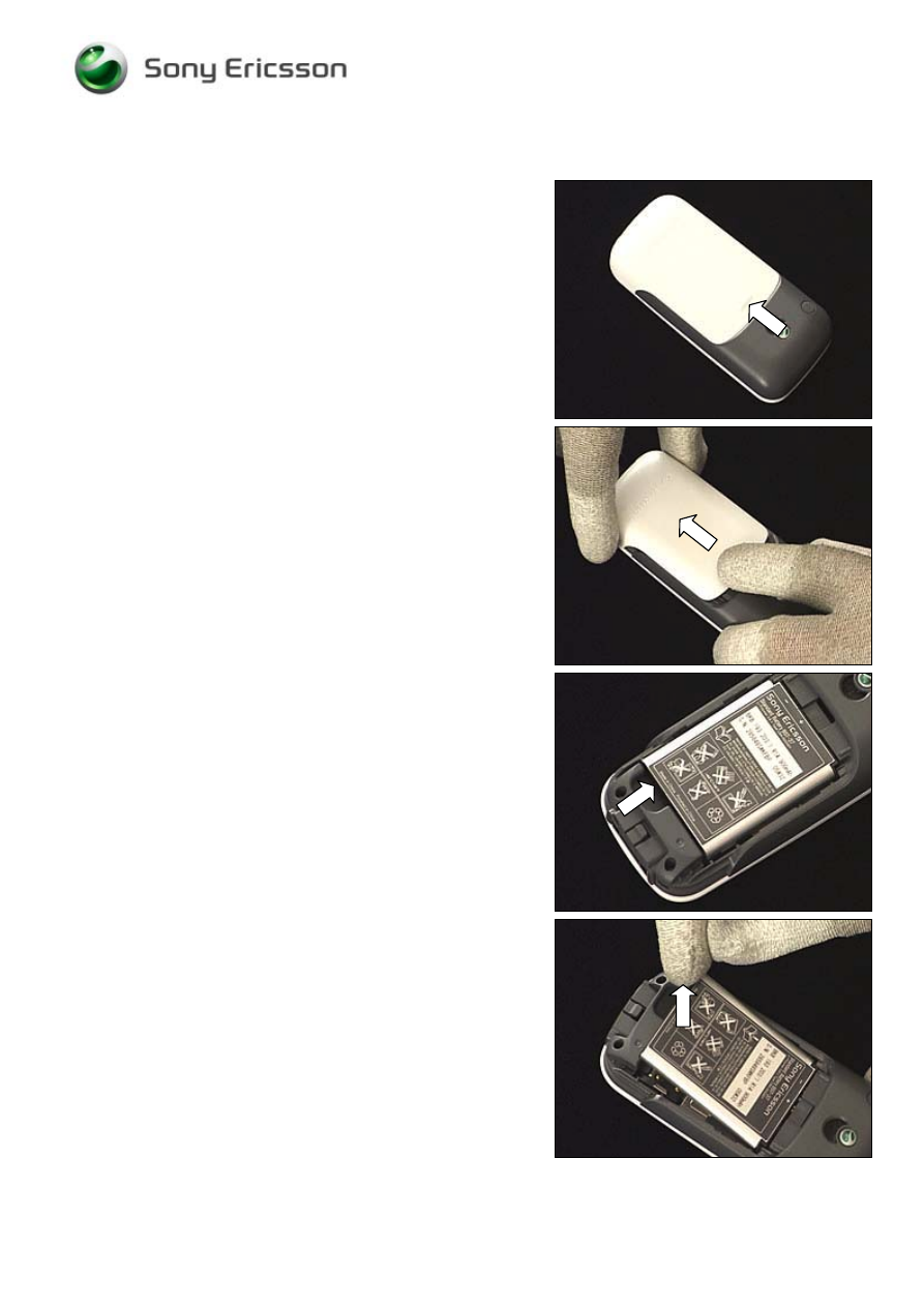
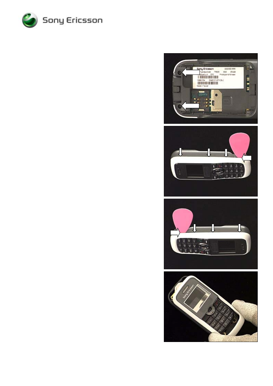
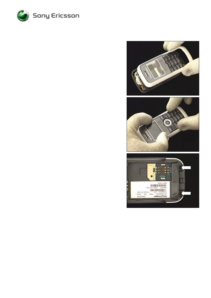
2.1.1 Battery Cover & Battery
Push on the bulge of the battery cover …
and slide the battery cover until it becomes released and
can be removed.
Put your finger here …
to raise and remove the battery.
Working Instruction, Mechanical
3/000 21-1/FEA 209 544/114 A
Company Internal
©
Sony Ericsson Mobile Communications AB
7(30)
2.1.2 Front Cover
Remove the two screws using torx bit no. 5 (T5).
THE SCREWS CANNOT BE REUSED
!
Insert the guitar pick at the bottom of the phone and slide it
towards the top to release the three snap hooks.
Repeat the procedure on the opposite side.
Gently wiggle the front cover and then remove it.
Working Instruction, Mechanical
3/000 21-1/FEA 209 544/114 A
Company Internal
©
Sony Ericsson Mobile Communications AB
8(30)
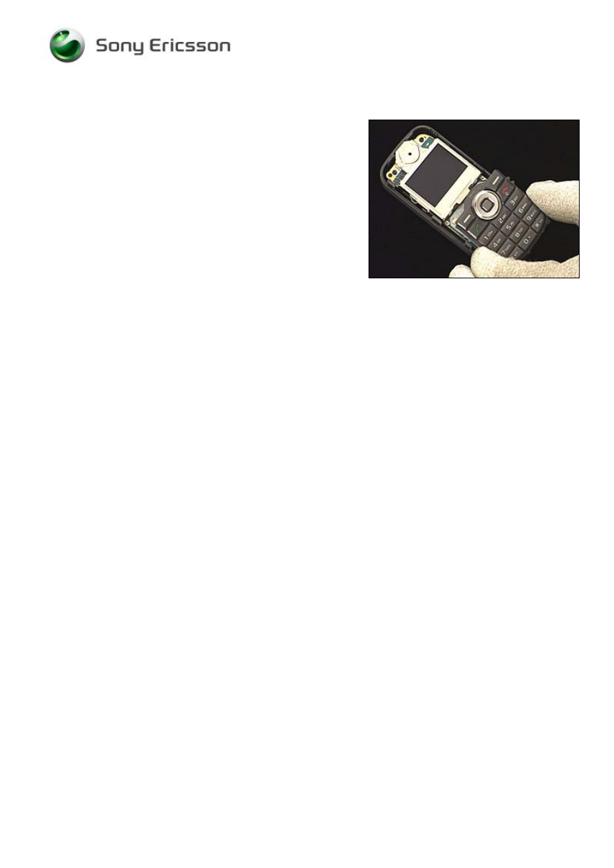
2.1.3
Keypad
Remove the keypad by lifting it straight up.
Working Instruction, Mechanical
3/000 21-1/FEA 209 544/114 A
Company Internal
©
Sony Ericsson Mobile Communications AB
9(30)
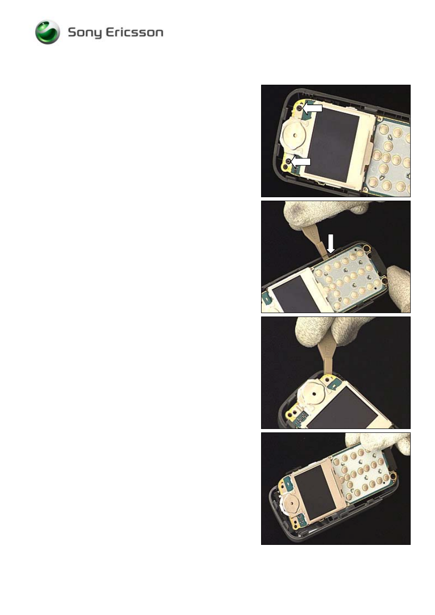
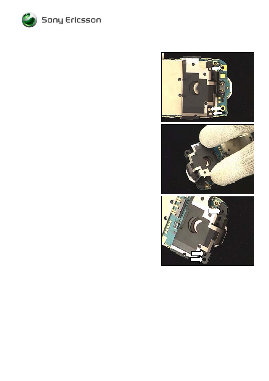
2.1.4
PBA
Remove the two screws using torx bit no. 5 (T5).
THE SCREWS CANNOT BE REUSED
!
Insert the ‘front opening tool’ next to the snap hook (at the
arrow) and bend to release the PBA from the snap hook.
Release the PBA at the top right corner.
Gently wiggle the PBA and then remove it.
Working Instruction, Mechanical
3/000 21-1/FEA 209 544/114 A
Company Internal
©
Sony Ericsson Mobile Communications AB
10(30)
2.1.5
Antenna
ass’y
Release the snap hook with the ‘front opening tool’ and,
if necessary, do the same on the opposite side.
Carefully lift off the antenna ass’y.
Working Instruction, Mechanical
3/000 21-1/FEA 209 544/114 A
Company Internal
©
Sony Ericsson Mobile Communications AB
11(30)
3 Replacements
Search for the part to be replaced on the Contents page and go to that instruction to be found in this
Replacements section.
The instruction usually begins by directing you to the Disassembly section with a specification of the
instructions you have to carry out in order to disassemble the phone as far as needed before the
actual replacement.
Go back to this Replacements section and carry out the instruction.
The instruction usually ends by directing you to the Reassembly section with a specification of the
instructions you have to carry out in order to reassemble the phone.
Start
Done
REPLACEMENTS
DISASSEMBLY
REASSEMBLY
Contents
page

Working Instruction, Mechanical
3/000 21-1/FEA 209 544/114 A
Company Internal
©
Sony Ericsson Mobile Communications AB
12(30)
3.1 Battery
Cover
Follow the 2.1.1 Disassembly instructions!
Prepare the new battery cover.
Follow the 4.1.5 Reassembly instructions!
3.2 Front
Cover
Follow the 2.1.1 – 2.1.2 Disassembly instructions!
Prepare the new front cover.
Attach a name plate as described in 3.14 Name Plate.
Follow the 4.1.4 – 4.1.5 Reassembly instructions!
3.3 Keypad
Follow the 2.1.1 – 2.1.3 Disassembly instructions!
Prepare the new keypad.
Follow the 4.1.3 – 4.1.5 Reassembly instructions!
3.4 Antenna
ass’y
Follow the 2.1.1 – 2.1.5 Disassembly instructions!
Prepare the new antenna ass’y.
Install a loudspeaker as described in 3.9 Loudspeaker ass’y.
Follow the 4.1.1 – 4.1.4 Reassembly instructions!
3.5 Rear
Cover
Follow the 2.1.1 – 2.1.4 Disassembly instructions!
Prepare the new rear cover.
Install the loudspeaker gasket as described in 3.10 Loudspeaker Gasket.
Install the microphone as described in 3.11 Microphone.
Install the vibrator as described in 3.12 Vibrator.
Install the RF cover as described in 3.13 RF Cover.
Attach a label as described in 3.15 Label.
Follow the 4.1.4 – 4.1.5 Reassembly instructions!
Working Instruction, Mechanical
3/000 21-1/FEA 209 544/114 A
Company Internal
©
Sony Ericsson Mobile Communications AB
13(30)
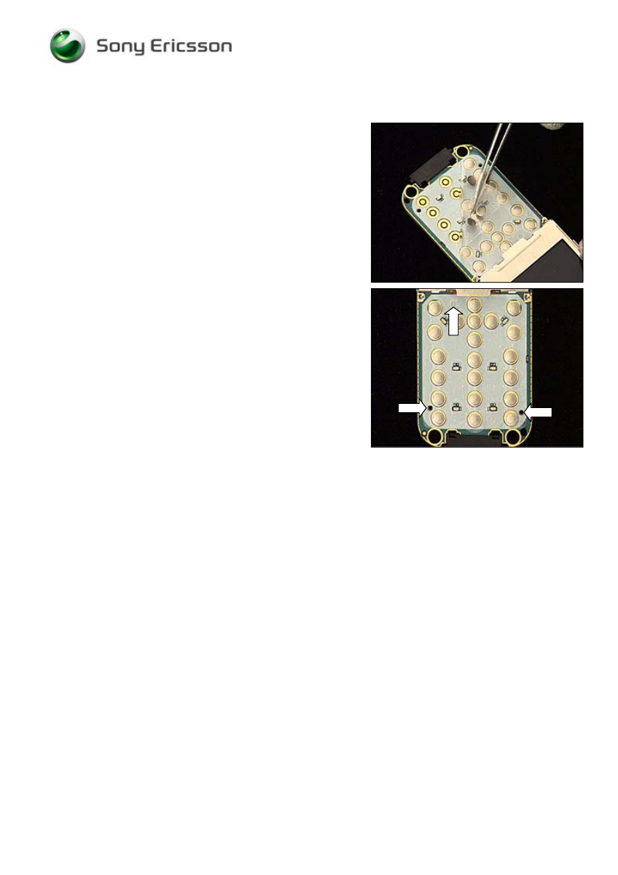
3.6 Dome Foil
Follow the 2.1.1 – 2.1.4 Disassembly instructions!
Use the tweezers to peel off the dome foil from the PBA.
Attach the new dome foil so that the three holes of the PBA
and the dome foil are perfectly aligned.
Follow the 4.1.2 – 4.1.5 Reassembly instructions!
Working Instruction, Mechanical
3/000 21-1/FEA 209 544/114 A
Company Internal
©
Sony Ericsson Mobile Communications AB
14(30)
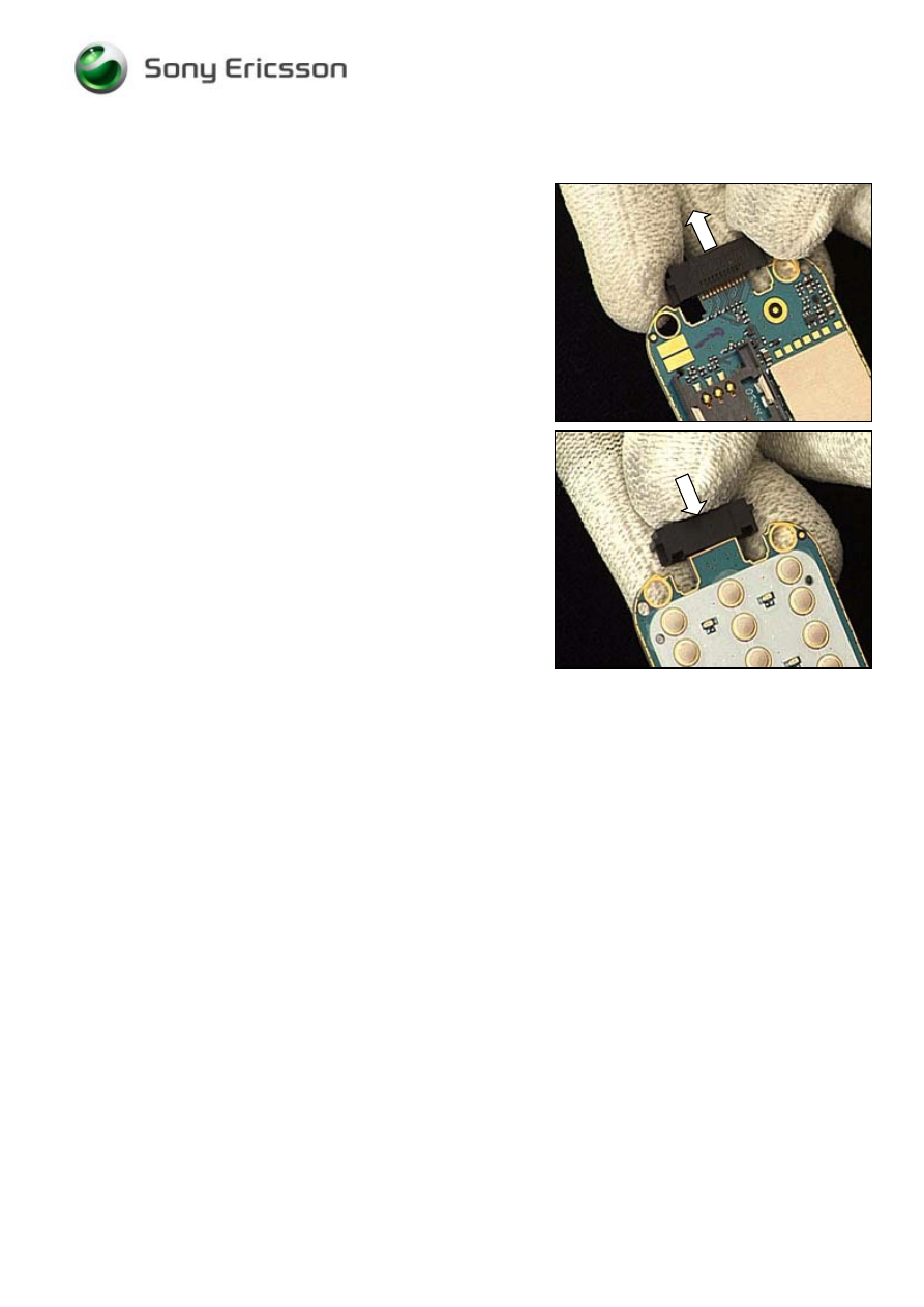
3.7 System
Connector
Follow the 2.1.1 – 2.1.4 Disassembly instructions!
Pull the system connector away from the PBA.
Push the system connector onto the PBA.
Follow the 4.1.2 – 4.1.5 Reassembly instructions!
Working Instruction, Mechanical
3/000 21-1/FEA 209 544/114 A
Company Internal
©
Sony Ericsson Mobile Communications AB
15(30)
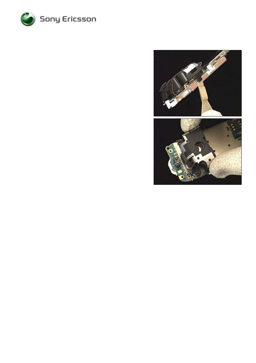
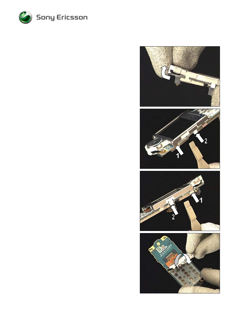
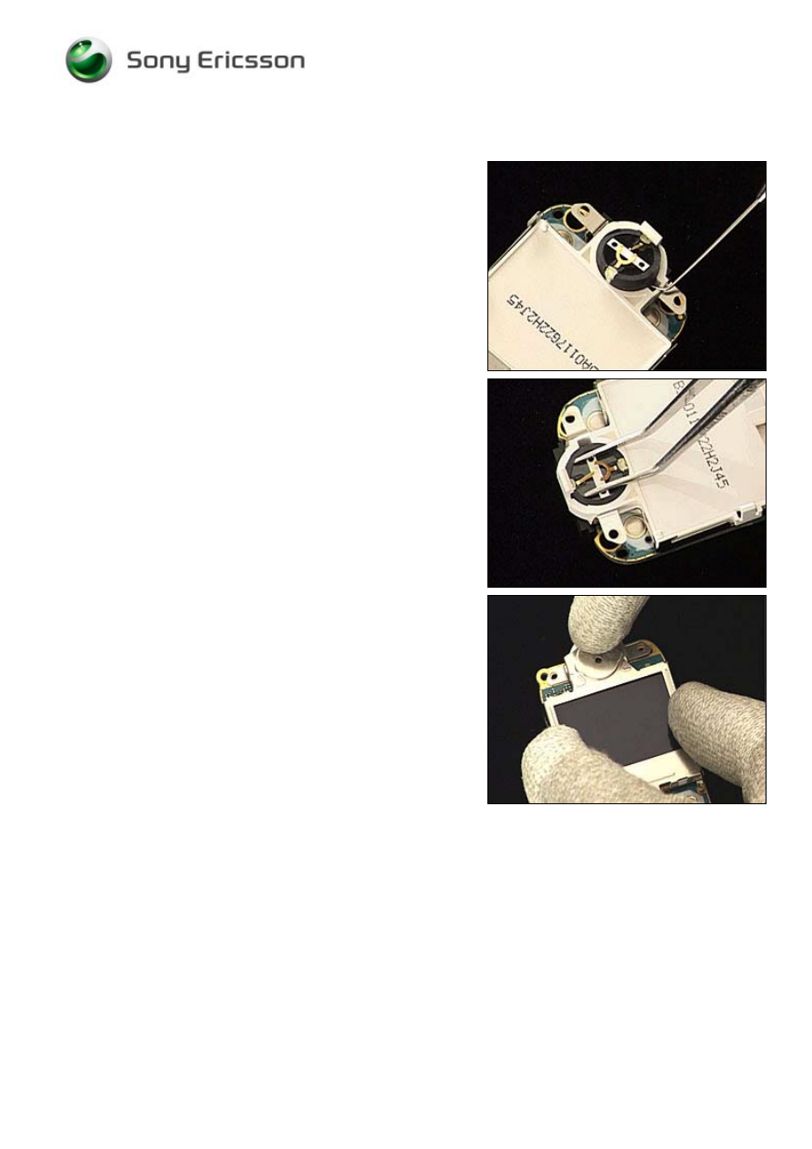
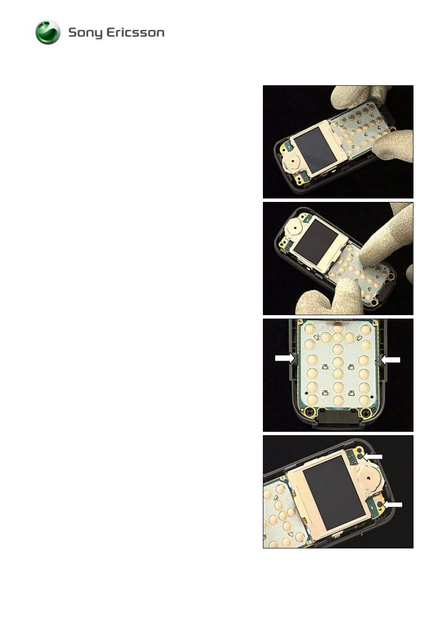
3.8 Earphone
ass’y
Follow the 2.1.1 – 2.1.5 Disassembly instructions!
HANDLE THE TOP HOOK WITH UTMOST CARE TO AVOID
DAMAGES TO THE SIDE HOOKS
!
Gently unsnap the top hook by using your fingers.
Unsnap side hook no. 1 with the ‘front opening tool’
followed by hook no. 2.
Do the same on the opposite side.
Turn the LCD unit to make it rest on the dome switches.
Working Instruction, Mechanical
3/000 21-1/FEA 209 544/114 A
Company Internal
©
Sony Ericsson Mobile Communications AB
16(30)
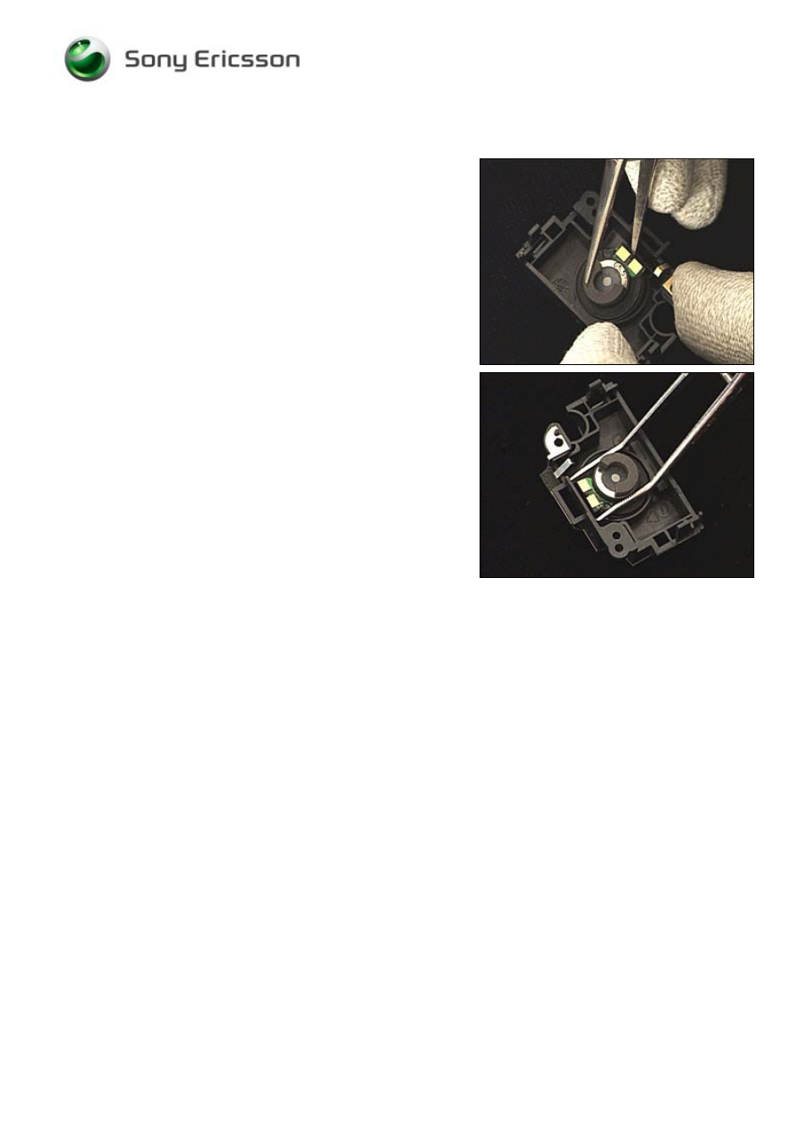
Earphone continued
Use the dentist hook to raise the earphone ass’y out of its
cavity and remove it with the tweezers.
BE CAREFUL NOT TO TOUCH THE GOLDEN CONTACT SPRINGS
OF THE EARPHONE ASS
’
Y
!
Use the tweezers to place the earphone ass’y in its proper
position and press gently until it reaches the bottom of the
cavity.
Turn the LCD unit back to its original position and press
simultaneously on both sides and on the top to make the
LCD unit snap onto the PBA.
Follow the 4.1.1 – 4.1.5 Reassembly instructions!
Working Instruction, Mechanical
3/000 21-1/FEA 209 544/114 A
Company Internal
©
Sony Ericsson Mobile Communications AB
17(30)
3.9 Loudspeaker ass’y
Follow the 2.1.1 – 2.1.5 Disassembly instructions!
Insert one leg of the tweezers underneath the golden
contacts and push to raise the loudspeaker ass’y out of its
cavity until it can be removed.
Use the tweezers to place the loudspeaker ass’y in its
proper position and press gently to secure its position
without touching the golden contacts.
Follow the 4.1.1 – 4.1.5 Reassembly instructions!
Working Instruction, Mechanical
3/000 21-1/FEA 209 544/114 A
Company Internal
©
Sony Ericsson Mobile Communications AB
18(30)
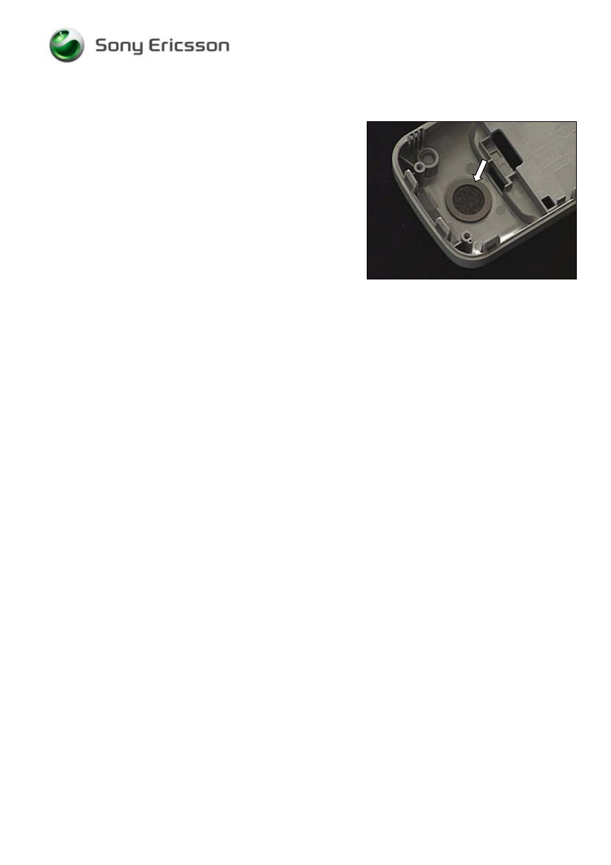
3.10 Loudspeaker Gasket
Follow the 2.1.1 – 2.1.4 Disassembly instructions!
Remove the gasket with a dentist hook and the tweezers.
Clean the surface with isopropyl alcohol.
Then attach the new loudspeaker gasket.
Follow the 4.1.2 – 4.1.5 Reassembly instructions!
Working Instruction, Mechanical
3/000 21-1/FEA 209 544/114 A
Company Internal
©
Sony Ericsson Mobile Communications AB
19(30)
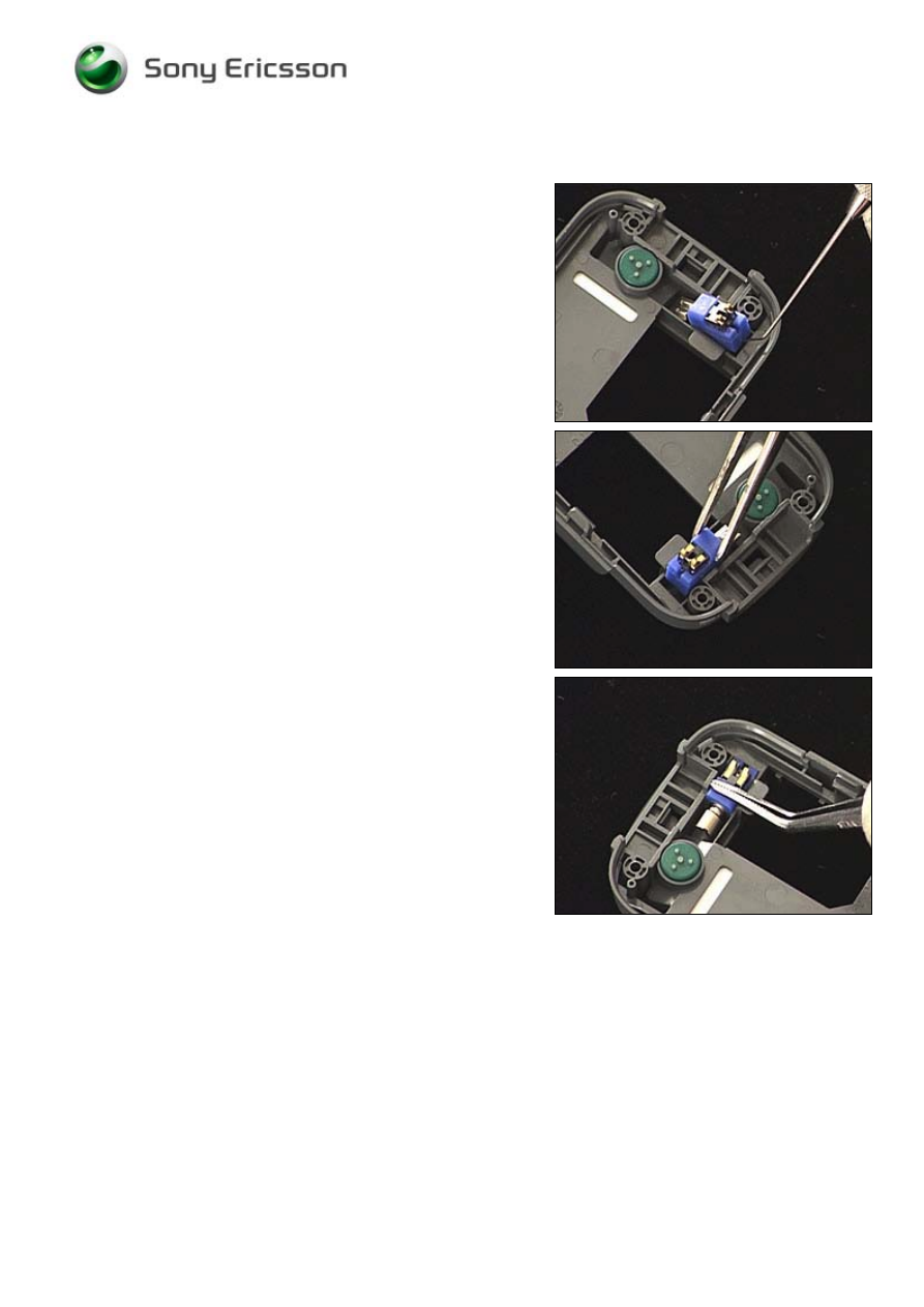
3.11 Microphone
Follow the 2.1.1 – 2.1.4 Disassembly instructions!
Use the dentist hook to raise the microphone out of its
cavity and then remove it with the tweezers.
Use the tweezers to place the microphone in its proper
position …
and press gently until it reaches the bottom of the cavity .
Follow the 4.1.2 – 4.1.5 Reassembly instructions!
Working Instruction, Mechanical
3/000 21-1/FEA 209 544/114 A
Company Internal
©
Sony Ericsson Mobile Communications AB
20(30)
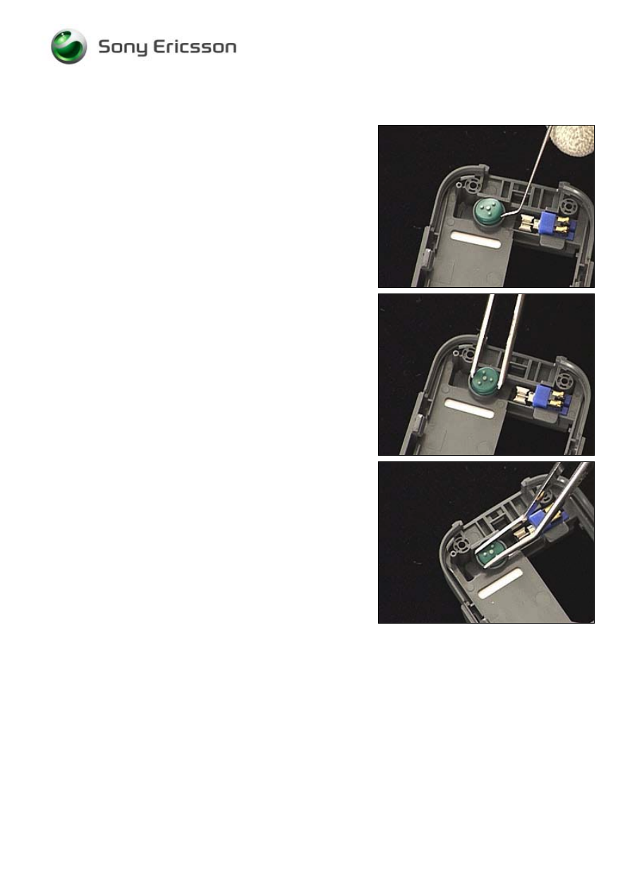
3.12 Vibrator
Follow the 2.1.1 – 2.1.4 Disassembly instructions!
Use the dentist hook to raise the vibrator out of its cavity
and then remove it with the tweezers.
DO NOT TOUCH THE CONTACT SPRINGS
!
Use the tweezers to place the vibrator in its proper position,
and press gently until it reaches the bottom of the cavity
without touching the contact springs.
Follow the 4.1.2 – 4.1.5 Reassembly instructions!
Working Instruction, Mechanical
3/000 21-1/FEA 209 544/114 A
Company Internal
©
Sony Ericsson Mobile Communications AB
21(30)
3.13 RF Cover
Use the dentist hook to raise the RF cover out of its cavity
and then remove it with the tweezers.
Use the tweezers to place the RF cover in its proper
position, and press …
until it reaches the bottom of the cavity.
Working Instruction, Mechanical
3/000 21-1/FEA 209 544/114 A
Company Internal
©
Sony Ericsson Mobile Communications AB
22(30)
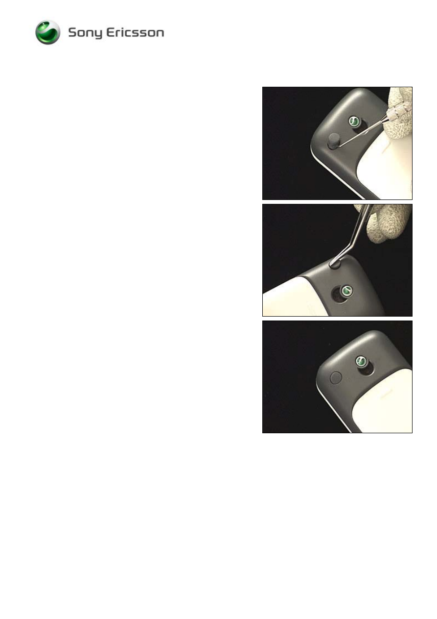
3.14 Name Plate
Remove the name plate with a dentist hook and the
tweezers.
Clean the surface with isopropyl alcohol.
Attach the new name plate using the tweezers and your
fingers.
Working Instruction, Mechanical
3/000 21-1/FEA 209 544/114 A
Company Internal
©
Sony Ericsson Mobile Communications AB
23(30)
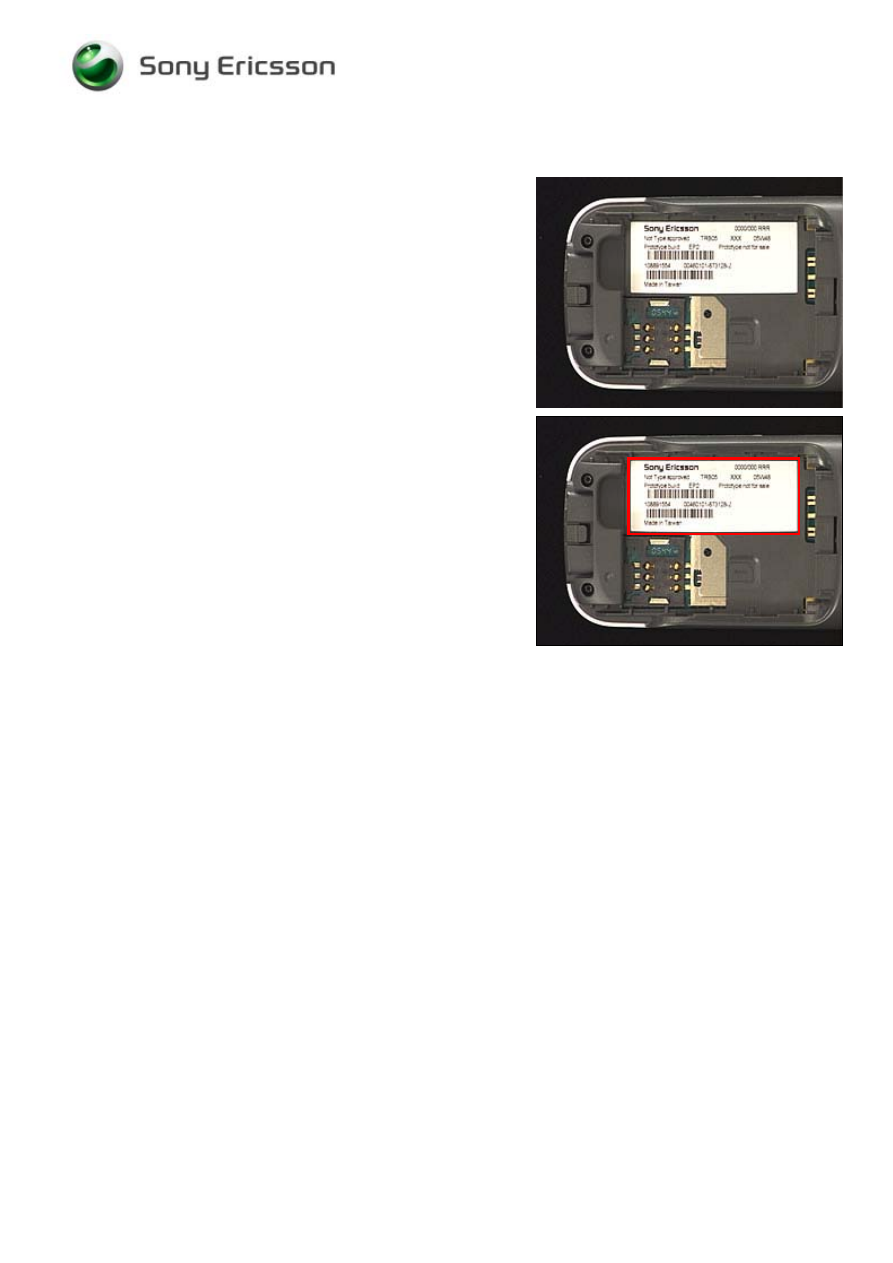
3.15 Label
Follow the 2.1.1 Disassembly instructions!
Read the old label and/or write the information into the
“Label make” program before removal
Note the position of the label before removal
Heat up the label by using hot air, if needed.
Carefully remove the label without causing scratches
If there still are residues, clean the surface with isopropyl
alcohol
Check that the proper label format is loaded in the Zebra
printer.
Write a new label by using the program “Label make” and
check that the printing is OK.
Take the new label and place it onto the frame as in the
adjacent picture.
ONE LABEL ONLY IS ALLOWED
!
Follow the 4.1.5 Reassembly instructions!
Working Instruction, Mechanical
3/000 21-1/FEA 209 544/114 A
Company Internal
©
Sony Ericsson Mobile Communications AB
24(30)
4 Reassembly
After replacing a part being listed in Replacements, the instruction of that section usually ends by
directing you to this Reassembly section with a specification of the instructions you have to carry out
in order to reassemble the phone.
4.1 Overview
The reassembly is done in the following sequence:
1. Antenna ass’y
2. PBA
3. Keypad
4. Front Cover
5. Battery (a) and Battery Cover (b)
Start
Done
REPLACEMENTS
DISASSEMBLY
REASSEMBLY
Contents
page
Working Instruction, Mechanical
3/000 21-1/FEA 209 544/114 A
Company Internal
©
Sony Ericsson Mobile Communications AB
25(30)
4.1.1 Antenna
ass’y
Place the antenna ass’y on the PBA so that the three holes
on the antenna ass’y are placed on top of the three holes
on the PBA.
Press simultaneously on both sides to make the antenna
ass’y snap onto the PBA.
Check the alignment of the holes.
Working Instruction, Mechanical
3/000 21-1/FEA 209 544/114 A
Company Internal
©
Sony Ericsson Mobile Communications AB
26(30)
4.1.2 PBA
Place the PBA into the rear cover.
Press simultaneously on both sides of the PBA where the
snap hooks of the rear cover are located.
Check that the PBA is secured by the two snap hooks.
Use 11 Ncm (±0.6 Ncm) torque to tighten two new T5
screws.
Working Instruction, Mechanical
3/000 21-1/FEA 209 544/114 A
Company Internal
©
Sony Ericsson Mobile Communications AB
27(30)
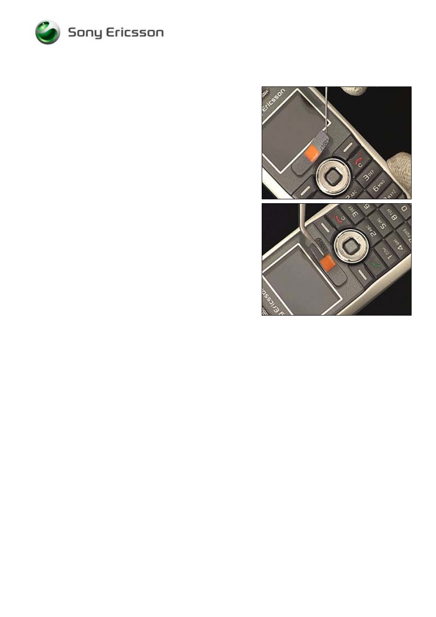
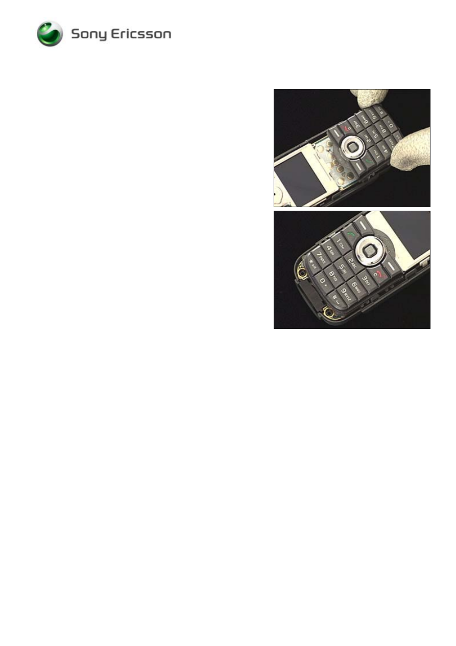
4.1.3 Keypad
Place the keypad on the dome switches …
like this.
Working Instruction, Mechanical
3/000 21-1/FEA 209 544/114 A
Company Internal
©
Sony Ericsson Mobile Communications AB
28(30)
4.1.4 Front
Cover
Place the front cover on top of the rear cover.
Press simultaneously on these four spots.
Check on both sides that the front cover is snapped to the
rear cover.
Use 11 Ncm (±0.6 Ncm) torque to tighten two new T5
screws.
Working Instruction, Mechanical
3/000 21-1/FEA 209 544/114 A
Company Internal
©
Sony Ericsson Mobile Communications AB
29(30)
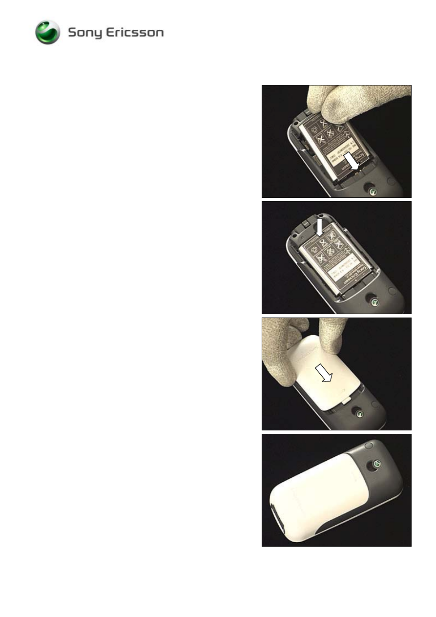
4.1.5 Battery & Battery Cover
Push the battery towards the battery connector …
and press it down at the bottom.
Place the battery cover on top of the battery and push
towards the top of the phone …
until the battery cover is latched in this position.

Working Instruction, Mechanical
3/000 21-1/FEA 209 544/114 A
Company Internal
©
Sony Ericsson Mobile Communications AB
30(30)
5 Revision history
Rev.
Date
Changes / Comments
A 2006-04-10
First
release
Wyszukiwarka
Podobne podstrony:
Sony Ericsson W595 Service Manual
Sony Ericsson K330i Service Manual
sony MDS 302 sup2 service manual
Service Manual Sony TFT LCD Color Monitor CPD L133 Schematic
hplj 5p 6p service manual vhnlwmi5rxab6ao6bivsrdhllvztpnnomgxi2ma vhnlwmi5rxab6ao6bivsrdhllvztpnnomg
Oberheim Prommer Service Manual
Korg SQ 10 Service Manual
MAC1500 service manual
Sony Ericsson GC79, TELEFONIA, Opisy telefonów
Kyocera Universal Feeder UF 1 Service Manual
Proview RA783 LCD Service Manual
indesit witp82euy Service Manual
Glow Worm installation and service manual Hideaway 70CF UIS
Proview PZ456 LCD Service Manual
Glow Worm installation and service manual Ultimate 50CF UIS
ewm2000 service manual
Glow Worm installation and service manual Ultimate 60CF UIS
Proview SH770I LCD Service Manual
więcej podobnych podstron