4
4
4-1
Samsung Electronics
Summary of product
Service Manual
4. Summary of Product
This chapter describes the functions and operating principals of the main components.
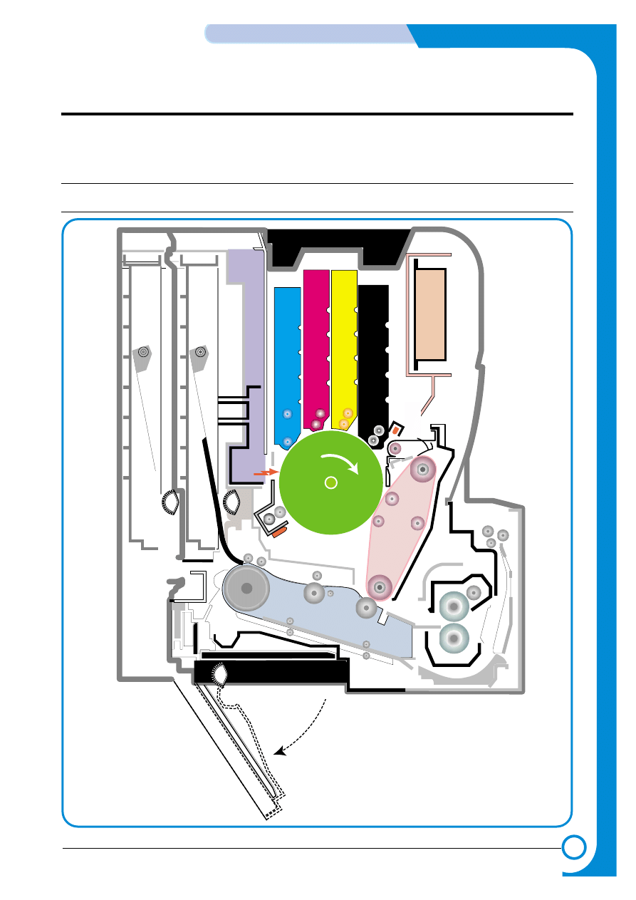
4.1 System Structure
4.1.1 Main Parts of System
HVPS
Eraser Lamp
Eraser Lamp
HVPS
DEV
. - Black
DEV
. -
Yellow
OPC
Pick-up
Roller
DEV
. - Magenta
DEV
. - Cyan
CASSETTE
LSU
ITB Unit
Feeder
DUPLEX
T2 Roller
Fuser Unit
EXIT Unit
MPF Path
MPF
MPT
DEV
. - Black
DEV
. -
Yellow
OPC
Pick-up
Roller
DEV
. - Magenta
DEV
. - Cyan
SCF
SCT
FCT
LSU
Deve Cover
Deve Cover
ITB Unit
Feeder
DUPLEX
T2 Roller
Fuser Unit
EXIT Unit
PTLPTL
SCF Path
Pick-up
Roller
Pick-up
Roller
Pick-up
Roller
Pick-up
Roller
4-2
Summary of Product
Samsung Electronics
Service Manual
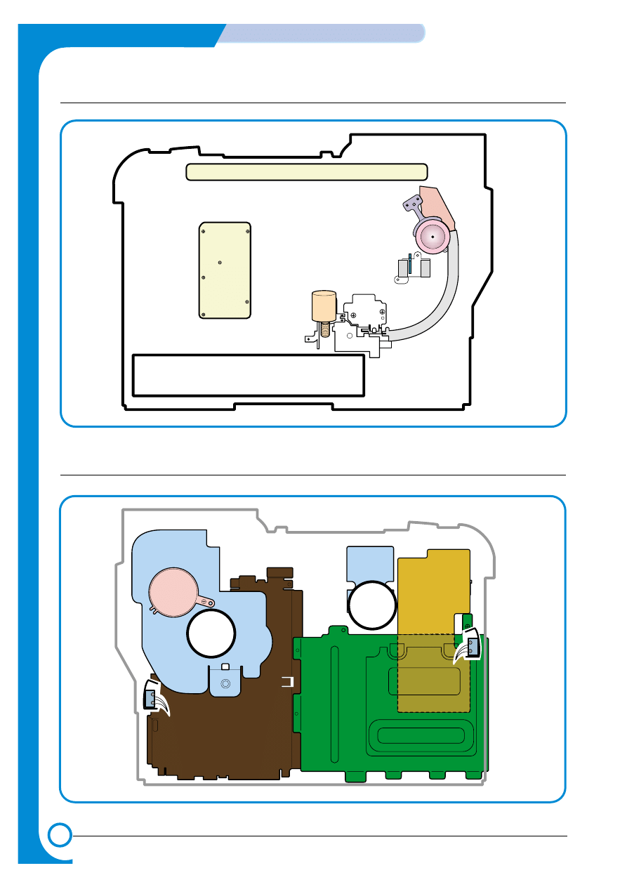
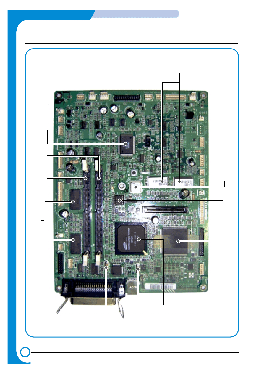
>> Front View
Deve OEM
PBA
Panel PBA
Waster Toner Sensor
Waster Toner Motor
SMPS
SMPS
Main Drive
Main Drive
Fuser Fan
Fuser Fan
Deve Drive
Deve Drive
Deve Drive PBA
Deve Drive PBA
Duplex Cover
Open S/W
Duplex Cover
Open S/W
Deve Cover
Open S/W
Deve Cover
Open S/W
Main Conrtoller PBA
Main Conrtoller PBA
>> Rear View

4-3
Samsung Electronics
Summary of product
Service Manual
1) OPC Unit
Images are created on the OPC unit using an electro-photographic process. The unit consists of:-
* OPC Drum
* Waste Toner Ass'y
used to collect waste toner remaining on the OPC drum,
* Charge Roller Assy
* Etc.
2) ITB Unit
ITB stands for Image Transfer Belt. An image developed on the OPC Drum is transferred first to the
ITB. This is called the T1 Transfer (Primary Image Transfer).
Images are built up in layers on the ITB.
First the Yellow (Y) colour image is created on the OPC and transferred to the ITB
Next the Magenta (M) colour image is created on the OPC and transferred to the ITB
Followed by the Cyan (C) and Black (K) images.
3) Transfer Roller
Once the complete, full colour, image, has been built up on the ITB the Transfer Roller is used to
transfer the image onto paper. This is called the T2 Transfer (Secondary Image Transfer)
4) FCT (First Cassette Tray)
It stores and automatically feeds print paper.
Pick-up Roller picks up paper, controls drive, feeds paper, removes static electricity, and so on.
> Spec.
* Paper arrange way : Side Registration
* Paper Direction : FISO (Front-in, Side-Out)
* Cassette Type : A4, Ltr
* Paper Discharge : Separation Claw
* Capacity : 250 Sheets (Standard paper 75mg/m? 20lb)
* Paper Size : A4, Letter
* Paper Weight (average) : 60~90g/m
2
(16~24lbs)
* Paper Type : General Printing Paper
* Additional Function : Paper Empty Sensor
5) SCT (Second Cassette Tray)
This additionally stores and automatically feeds printing paper. Its function is the same as the FCT
(First Cassette Tray)
> Spec.
* Paper arrangement : Side Registration
* Paper Direction : FISO (Front-in, Side-Out)
* Cassette Type : A4, Ltr
* Paper Discharge : Separation Claw
* Capacity : 500 Sheets (Standard paper 75mg/m
2
20lb)
* Paper Size : A4, Letter
* Paper Weight (average) : 60~90g/m
2
(16~24lbs)
* Paper Type : General Printing Paper
* Additional Function : Paper Empty Sensor

4-4
Summary of Product
Samsung Electronics
Service Manual
6) MPT (Multi Purpose Tray)
The Multi-Purpose Tray not only feeds general printing paper but is also used for many other kinds
of paper such as those paper sizes not supported by the cassette, envelopes, OHP, etc.
> Spec.
* Capacity : Cut Sheet : 100 Sheets (Standard paper 75mg/m
2
20lb)
* OHP : 300 Sheets
* Envelope & Label & Card Stock : 10 Sheets
* Paper Arrangement : Side Registration
* Power : Main Motor (BLDC)
* Driving Management : Solenoid
* Paper Discharge : Friction Pad Method
* Paper Size : Legal, Folio, A4, Letter, Executive, JIS B5, A5, A6
* Paper Weight (Average) : 60~163g/m
2
* Paper Type : General, Label, Post Card, Transparency, Envelope, Card Stock (Tracing
Paper is not served)
* Additional Function : Paper Empty Sensor
7) Feeder
* Paper Arrangement : Side Registration.
* Power : Main Motor (BLDC)
* Paper Management : Solenoid
8) Duplex Unit
The Duplex Unit is used to reverse feed paper when printing on the second side (known as Double
sided or Duplex printing). The Duplex Unit is not an optional extra, it is built-in at manufacturing
time and is integral with the Transfer Roller.
> Spec.
* Power : Main Motor (BLDC)
* Paper Reverse Function: After the front side of the original document is printed, it trans-
fers the printing paper to the duplex unit for printing the reverse side of original document
which is reverse fed by the exit roller.
9) Exit Unit
The Exit Unit guides paper that is just about to leave the print engine. Printed-paper is discharged
by Exit Roller and Kicker into the Output Tray.
> Spec.
* Capacity : 250 sheets (Standard A4, 75g/m2)
* Paper Direction : Face Down
* Exit Drive Roller : It is driven by Main Motor (BLDC), and it rotates clockwise for normal
feed and antic-clockwise when reverse feeding for duplex printing.
* Bin Full Sensor : There is no Bin Full sensor fitted on this model.
10) Toner Cartridge
There are four toner cartridges, each containing a different colour ink : C (Cyan), M (Magenta), Y
(Yellow) , and K (Black).
Each one of these toner cartridge is independent and can be changed independently.
11) Fuser Unit
This unit consists of 2 Heat Lamps, 2 Heat Rollers, 2 Thermostats and a Thermister. It melts and
fuses the toner, transferred by the transfer roller onto the paper, by applying pressure and high
temperature to complete printing job.
12) LSU
This is a core part of LBP. It forms a latent image on the surface of OPC drum using a static
charge.
* Resolution: Real 600 dpi

4-5
Samsung Electronics
Summary of product
Service Manual
13) Main Drive Unit
This motor drives, by way of a gearbox, the OPC unit, ITB unit, feeder unit, fuser unit, exit unit and
duplex unit.
> Spec.
* Power : 40W Max (24V)
* Drives : OPC unit, ITB unit, Fuser, Feeder, Duplex unit, Exit unit
14) DEVE Drive Unit
This motor drives, by way of a gearbox, the toner cartridges and ITB cleaning cam.
> Spec.
* Power : 40W Max (24V)
* Drives : DEV (4 Color)/ITB Cleaning)
15) SMPS (Switching Mode Power Supply)
This power supply uses the AC supply voltage to generate the DC voltages used by the system.
The SMPS has 3 output channels (+3.3V, +5V, +24V).
The AC Heater Control Unit that supplies power to the fuser is also located on the SMPS.
16) HVPS (High Voltage Power Supply)
The HVPS creates the high voltages (Charger, Supply, T1, T2, Developer) used for the electro pho-
tographic process. The high voltage is created from the 24V line from the SMPS. High Voltage out-
put is supplied to the toner cartridge, OPC drum unit, ITB unit, and Transfer roller.
17) Main Controller PBA
The Main controller PBA is very important as it is the heart of printer. It has several major function
blocks.
* CPU and SPGPi Block: This manages the printing order from the host, creates bitmap data for
the engine to print and controls various devices that are needed to operate the printer.
*Engine Control Block: This manages images and controls various kinds of I/O
* Memory Block : The operating system uses this to store video data and printing orders given by host.
* ROM Block : The printer OS and PDL Interpreter are stored here.
* In addition there are USB 2.0 Block, IEEE 1284 Block, Option Block, OPE Panel, etc.
18) DEVE Drive PBA
Each toner cartridge requires the Supply HV only when that colour image is being processed. This
unit takes its HV source from the HVPS and using 4 solenoids selects which cartridge is to receive
the Supply voltage. This section also contains the DEVE motor, DEVE clutch, and DEVE solenoid
drives. These are activated in sequence as required by the printing process.
19) DEVE OEM PBA
This detects new or used toner cartridges and also checks that cartridges are approved parts. If a
toner cartridge is not suitable for the machine an error message is displayed.
20) Waste Toner Ass’y
A cleaner blade on the OPC unit cleans waste toner from the OPC drum after every image is trans-
ferred to the ITB. Once the complete image is transferred from the ITB onto paper the ITB Cleaning
Solenoid activates and a cleaning blade removes waste toner from the ITB. Waste toner is trans-
ferred to the waste toner tank.
The error message "Waste Toner Tank Full/ Not Install" is indicated on the LCD Panel. Replace the
Waste Toner Tank immediately or the printer may be damaged
4-6
Summary of Product
Samsung Electronics
Service Manual
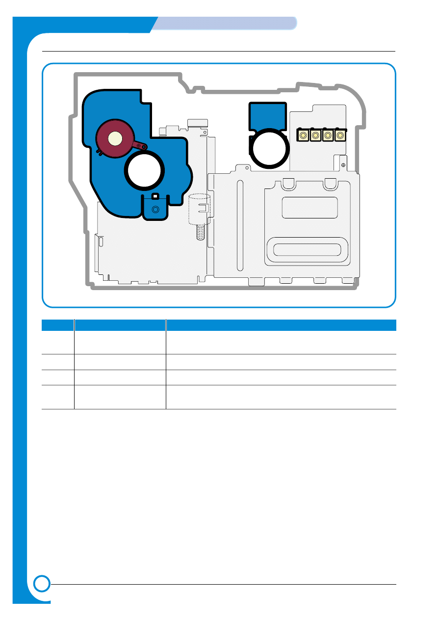
4.1.2 Motor & Fan Layout
3. Fuser Fan
1. Main Motor
2. DEVE Motor
4. Waste Toner Motor
3. Fuser Fan
1. Main Motor
2. DEVE Motor
4. Waste Toner Motor
NO.
Name
Description
1
Main Motor
Drives the OPC unit, ITB unit, feeder unit, fuser unit, exit unit and
duplex unit.
2.
DEVE Motor
Drives C, M, Y and K toner cartridges and ITB cleaning cam.
3.
Fuser Fan
Forces cold air into the printer and takes out heat from the fuser.
4.
Waste Toner Motor
Transfers collected waste toner from the OPC drum and ITB to the
waste toner tank. (Refer to front view picture on 4-2 page)
4-7
Samsung Electronics
Summary of product
Service Manual
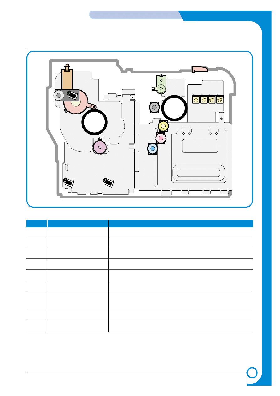
4.1.3 Clutch & Solenoid Layout
>>Solenoid
Cartridge Solenoid(C, M, Y, K)
Duplex Solenoid
ITB Cleaning
Solenoid
Black Deve
Clutch
Black Deve
Clutch
Yellow Deve Clutch
Magenta Deve Clutch
Cyan Deve Clutch
Cartridge Solenoid(C, K, Y, M)
Yellow Deve Clutch
Magenta Deve Clutch
Cyan Deve Clutch
T2 Home Solenoid
T2 Home Solenoid
MP Pick_up
Solenoid
MP Pick_up
Solenoid
Feed Regi
Clutch
Pick_up Solenoid
NO.
Name
Description
1.
C DEVE solenoid
Controls the High Voltage supply to the cyan cartridge.
2.
K DEVE solenoid
Controls the High Voltage supply to the black cartridge.
3.
Y DEVE solenoid
Controls the High Voltage supply to the yellow cartridge..
4.
M DEVE solenoid
Controls the High Voltage supply to the magenta cartridge.
5.
Pick-up solenoid
Controls the pick-up roller drive.
6.
MP Pick-up solenoid
Controls the MP pick-up roller drive.
7.
Duplex solenoid
When operating in duplex print mode, this reverses the direction
of paper feeding to feed paper into the duplex unit.
8.
T2 Home solenoid
This forces the transfer roller into contact with the ITB unit.
9.
ITB cleaning solenoid
This brings the cleaning blade into contact with the ITB unit
4-8
Summary of Product
Samsung Electronics
Service Manual
>>Clutch
NO.
Name
Description
1.
Yellow DEVE clutch
Controls Yellow color toner cartridge drive
2.
Magenta DEVE clutch
Controls Magenta color toner cartridge drive
3.
Cyan DEVE clutch
Controls Cyan color toner cartridge drive
4.
Black DEVE clutch
Controls Black color toner cartridge drive
5.
Feed Regi. Clutch
Controls the location of picked-up paper
4.1.4 Sensor & Micro S/W Layout
NO.
Name
Description
1.
Paper Empty Sensor(FCT)
This sensor detects paper in the first (main) cassette.
2.
Paper Empty Sensor(SCT)
This sensor detects paper in the second (optional) cassette.
3.
Paper Empty Sensor(MPT)
This sensor detects paper in the multi-purpose tray.
4.
Feed Sensor
This sensor must operate within a certain time after paper pick-
up otherwise a JAM is detected
5.
ITB Home Sensor
This detects the position of the image transfer belt, and in
dicates the start location for image writing. It is used to ensure
that all 4 colour images are correctly registered.
6.
CTD Sensor
This stands for Color Toner Density Sensor. It detects toner
density of each color image that is formed on the OPC drum.
7.
Waste Toner Sensor
This detects whether the waste toner tank is mounted or not and
the amount of waste toner in the tank.
8.
Exit Sensor
This detects whether printing paper is discharged or not.
9.
DEVE Cover Open S/W
This detects the open/closed status of the DEVE Cover.
10.
Duplex Cover Open S/W
This detects the open/closed status of the Duplex Cover.
Note:
* ITB Home Sensor and CTD Sensor are located in the ITB unit. If they develop a fault replace the
ITB unit.
* Please, refer to the Chap. 7 Arrangement and Adjustment, "Paper Path diagram", for the location
of the paper empty sensor, feed sensor, and exit sensor.
* Please, refer to page 4-2 for the location of the waste toner sensor, DEVE cover open S/W, and
duplex cover open S/W.

4-9
Samsung Electronics
Summary of product
Service Manual
4.1.5 Main Controller PBA
USB
Parallel Port
CN26
CN27
CN28
CN29
CN30
CN30
CN32
CN33
T2 HOME
BLDC1
FSR_ROLL
DIMM1_SLOT
DIMM2_SLOT
FUSER_F
AN
SMPS
MP
EMPT
MP
SOL
FEED
CN25
PICK_UP
CN23
CL
T_FEED
CN21
EMPT
CN9
CN1
CN16
SCF
CN12
LSU
CN6
OPC KEY
CN5
DEVE_DRIVER
DEVE_DRIVER
CN14
LSU SW
CN8
ERASER
CN35
LSU_F
AN
CN24
DUPLEX
CN19
EXIT
CN4
P
ANEL
CN7
HVPS
CN10
ITB
CN17
W
ASTE T
ONER
CN15
TH3
CN1
1
PTL
CN13
TH4
NIC
For T
est
4-10
Summary of Product
Samsung Electronics
Service Manual
FLASH
MEMOR
Y
(32Mbit)
OSC3
19.900614MHz
OSC2
12MHz
(Reserved)
OSC5
12.5MHz
OSC1
30MHz
IMAGE
PROCESSOR
(SPG P1)
MICRO PROCESSOR
(SPC6031FT226)
SDRAM(512Mbit)
DIMM2
LPEC1
(ENGINE CONTROL)
DIMM1
4-11
Samsung Electronics
Summary of product
Service Manual
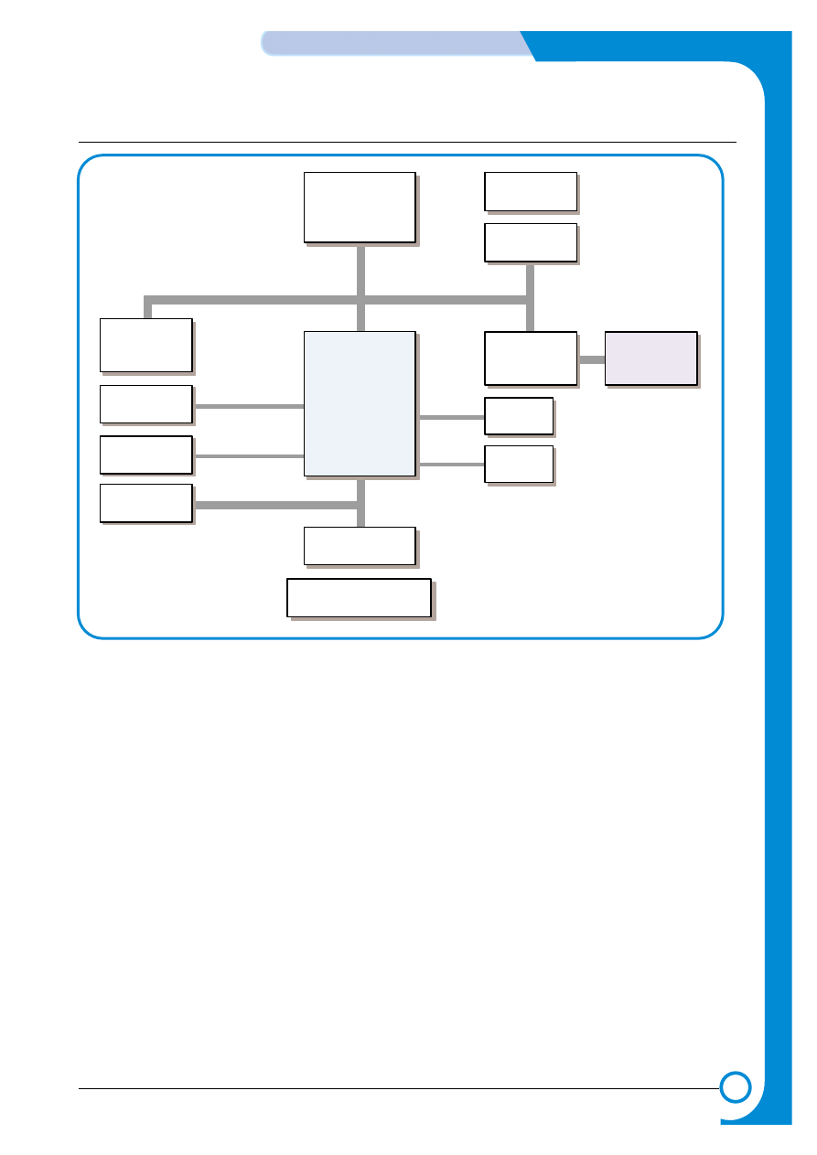
SPC603e
266MHz
SDRAM
64(128)MB
SDRAM DIMM
Optional:64, 128, 256MB
SPGPi
UART
Memory Bus 32-bit, 50MHz
System Bus 32-bit, 50MHz
NPC
Wire/Wireless
Optional
LPEC1
Engine Control
ASIC
Engine
Mecha
Flash Memory
8MB
Flash DIMM
Optional
UART
for debug
EEPROM
1KB
Panel
16X2 LCD
IEEE1284
USB2.0
1) CPU - SCP603e
A Motorola SPC603e 266MHz processor, running at 250MHz, is the main processor controlling the printer. It
has a 32 bit Motorola 603 bus operating at 50MHz which connects it to the Samsung SPGPi graphics
processor ASIC, optional NPC card, memory and the LPEC engine controller.
• High-performance, superscalar microprocessor
• Five independent execution units and one register file
• High instruction and data throughput
• 16-Kbyte data cache-four-way set-associative
• 16-Kbyte instruction cache-four way set-associative
• A 64-entry, two-way set-associative ITLB
• A 64-entry, two-way set-associative DTLB
• Four-entry data and instruction BAT arrays providing 128-Kbyte to 256-Mbyte blocks

4-12
Summary of Product
Samsung Electronics
Service Manual
• Facilities for enhanced system performance
. A 32-bit or 64-bit split-transaction external data bus with burst transfers
. Support for one-level address pipelining
• Integrated power management
. Low-power 1.8/3.3 volt (2.0/3.3 volt or 2.0/2.5 volt with 300MHz core speed) design
. Internal PLL that provides many processor/bus clock ratios
. Three power saving modes: doze, nap, and sleep
. Automatic dynamic power reduction when internal functional units are idle
• In-system testability and debugging features through JTAG boundary-scan capability
2) SPGPi
The Samsung SPGPi graphics processor ASCIC has all of the necessary functions to control the I/O and
manipulate images. It is a System Controller operated at 50MHz under control of the SPC603e CPU.
• Power PC Compatible Interface
• 3 Memory Bus Architecture
. ROM Bus, Primary DRAM Bus, Secondary SDRAM Bus for Band Buffer
• Direct connection to 4 ROM Banks
. 16 MByte Address Space per Bank
. Burst Capability
. Programmable Timing per Bank
• Direct connection to max 6 I/O Banks of ROM Bus
. 64 MByte Address Space per Bank
. Programmable Timing per Bank
• Direct connection to a maximum of 3 I/O Banks of DROM Bus for DMA
. 8 KByte Address Space per Bank
. Programmable Timing per Bank
• Direct connection to a maximum of 9 DRAM / SDRAM Banks
. Support EDO or FPM Type DRAM and SDRAM
. Max 128 MByte Address Space per Bank
. Programmable Timing to Control DRAM / SDRAM A.C Characteristics
. Supports Self Refresh for Data Retention
• Direct connection to 1 SDRAM Banks using Secondary Bus for Band Buffer
. Support SDRAM only
. Max 512 KByte Address Space
. Programmable Timing to Control SDRAM A.C Characteristics
. Supports Self Refresh for Data Retention
. Bus Traffic Sharing using Secondary Bus
• Graphic Coprocessor Core for Banding support of Printer Languages
. Supports up to 256 Bit Block Transfer
. Scan Line Transfer
. Polygon Filling
. Enhanced Graphic Commands compared to SPGP, SPGPe+
. Access to Secondary Bus

4-13
Samsung Electronics
Summary of product
Service Manual
• Parallel Port Interface Controller
. DMA based or Interrupt based Operation
. Supports IEEE Standard 1284 Communication
• UART
. 4 Independent Full Duplex UART (Interrupt Based Operation Only)
. max 16 Byte FIFO to Handle SIR Bit Rate Speed
• DMA
. 3 Channel General Purpose DMA Controller for High Speed I/O
. 8 bit, 16 bit, 32 bit Data Transfer Mode Support
• Timer
. 3 Independent Programmable Timer
. Watch Dog Timer for S/W Trap and Tone Generator for MFP Application
• RSH
. Fully H/W Rotator, Scaler and Halftoner
. Variable Image Scaler and Image Halftoning Unit for PCL6
• Compression / Decompression
. 3 Different Kinds of Codec Algorithm
. jCodec : Powerful T.85 JBIG Algorithm for Bi Level Image Compression
. gCodec
- Simplified JBIG Algorithm for Band Compression, coupled with GEU
- Access to Secondary Bus
. HCT : Halftone Compression Technology (Byte Run-Length Type)
. Independent Compression & Decompression Data Path of Each Codec
• Printer Video Controller
. 2 Different Kind of Printer Video Controller (Selected by S/W)
. High Performance DMA based Interface to Printer Engine
. PVC : Printer Video Controller without RET Algorithm
. HPVC
- Printer Video Controller with RET Algorithm
- Access to Secondary Bus
• Package : 352 pin BGA
• Power
. Core : 2.5V
. IO : 3.3V

4-14
Summary of Product
Samsung Electronics
Service Manual
3) Memory Block
The operating program runs from memory (see below). It is used to store video data and printing jobs from the host
Standard factory fitted memory is 64MB (128MBfor CLP-550N), and can be expanded using a DIMM module mounted
in the SODIMM connector. This is a user fit option, DIMMs from 64Mb - 256MB can be used giving a total of up to
320MB (384MB CLP-550N) of memory. DIMM modules are non standard – only Samsung product should be used.
The memory controller, located in the SPGPi, controls the SDRAM memory using a 32 bit 50 MHz bus.
4) ROM Block
An 8MB flash ROM is used to store the OS, Fonts are also stored in the flash ROM. An option DIMM module can be
fitted in the SODIMM connector if required. The flash Rom is controlled by the ROM Controller that is built into the
SPGPi processor.
5) USB 2.0 Block
A Netchip Co. NET2270 is used to provide support for USB2.0 and is capable of interface speeds up to 480Mbps.
Under control of the SPGPi chip DMA is used to transfer incoming data directly into memory.
6) IEEE1284 Block
An IEEE 1284 controller is controlled directly by the SPGPi processor. ECP mode is supported.
7) Option Block
An Ethernet card can be attached using the 100 pin connector. It is connected directly to the SPGPi processor and
communicates using a 16bit bus.
8) OPE Panel
The OPE panel is controlled by a UART Block located in the SPGPi and it displays printer status and helps the user
to setup the printer. Various data is transferred using a serial interface between a Mycom located in the OPE panel
and the UART in the SPGPi.
9) Memory
There are two types of memory, program memory that uses flash and a working memory that uses SDRAM. When
printing working memory is used as band memory.
10) LSU Control
The Laser motor and Laser LED are controlled by the LPEC engine controller.
11) Sensor
Various sensors are used to detect various conditions during the printing process. These include paper
empty sensor, feed sensor, exit sensor, CTD sensor, ITB sensor, etc.
12) Actuator Control
This section drives the various motors and clutches that are required for the paper feed and printing
process. These include DEVE cartridge clutches (4 off), Feed Regi clutch, DEVE solenoids (4 off), Pick
solenoids (2 off), Duplex solenoid, ITB and T2 solenoids.
13) ADC
The ADC unit is used to sense a number of analog parameters used in the set. These include Fuser and
Set temperatures, OPC, ITB and Toner OEM resistors, Waste Toner tank full / present, Waste Toner
Motor and T1 / T2 / Charge currents, CTD sensor.
14) DAC
The DAC is used to control the light intensity emitted by the CTD LED.
4-15
Samsung Electronics
Summary of product
Service Manual
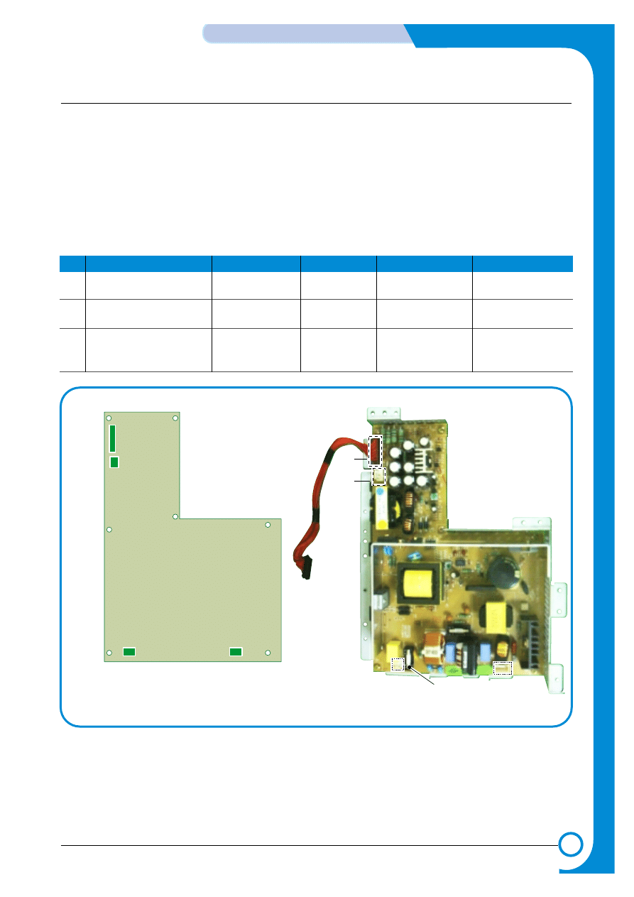
4.1.6 SMPS (Switching Mode Power Supply) PBA
The SMPS unit supplies DC power for driving the whole system, it also contains an AC heater control unit
that supplies power to the fuser.
1) DC output
- Main controller PBA, OP panel, SCF, Developer driver PBA
2) AC output
-Fuser unit (Heat lamp, Thermostat)
3) Output voltage
NO
Item
CH1
CH2
CH3
CH4
1
Channel name
+3.3V
+5V
+24.0V
+24.0VF
2
Rated outputting voltage
3.3V ± 4%
+5V ± 4%
+24V + 15%/-10%
+24V + 15%/-10%
3
Uses
MICOM,CMOS
MICOM,CMOS
MOTOR,FAN
MOTOR,FAN
LOGIC
LOGIC
CON4
CON3
CON4
CON3
CON4
CON3
CON1
CON1
Fuse
CON2
CON2
4-16
Summary of Product
Samsung Electronics
Service Manual
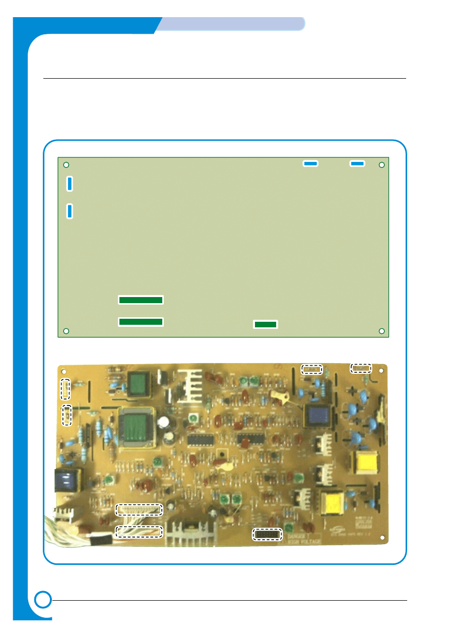
4.1.7 HVPS (High Voltage Power Supply) PBA
The HVPS PBA uses the 24V created by the SMPS to generate the high voltages used by the charger,
supply, T1,T2 and DEVE processes. For bests quality images these high voltages must be ,
controlled accurately to maintain the print quality. The high voltages produced are supplied to toner,
OPC cartridge, ITB unit, and transfer roller.
CHARGER
T1
T2
SUPPLY
CN1
CN2
T1
T2
CHARGER
CN1
CN2
SUPPLY
SUPPLY
T1
T2
CHARGER
CN1
CN2

4-17
Samsung Electronics
Summary of product
Service Manual
1) Charging Voltage: Charger
* Function : This high voltage is used to charge the surface of the OPC to about -500volt~800volt.
* Output voltage : -200V~-2.0KV DC +/- 3% (Duty is changeable, no loading)
* Error type :If MHV was not present, the surface of the OPC is not charged. As a result, toner on
the developer roller is transferred over to the OPC drum: therefore, black paper could
be printed out.
2) Transfer high voltage: T1(+)
* Function : This high voltage is used to transfer toner from the OPC drum to the ITB unit.
* Output voltage : +400V~ +3.5KV DC +/- 3% (Duty is changeable, no loading)
* Error type : If T1 was not present, it is not possible to transfer toner from the OPC drum to the
ITB. As a result, printer output could be faint.
3) Transfer High Voltage: T2 (+)
* Function : this high voltage is use to transfer toner from the ITB to the paper.
* Output voltage : +400V~ +5KV DC +/- 3% (Duty is changeable, no loading)
* Error type : If T2 was not present, it is not possible to transfer toner from the ITB to the paper. As
a result, printing output could be faint
4) Cleaning voltage: T2 (-)
* This high voltage is used to transfer (-)toner, remains on transfer roller, from the Transfer Roller
to the ITB unit.
* Output voltage : There is no feedback control, and it outputs a fixed voltage (-900V).
* Error type : Toner contamination occurs on the reverse side of the printed-paper.
5) Supplying voltage: Supply
* Function : Supply the duplicated (AC+DC) voltage from the HVPS to the Deve Drive Board.
* Output voltage
AC Voltage f : 1 KHz ~ 3KHz (Duty is changeable)
AC Voltage Vp-p : 1KV ~ 3KV
DC : -100V ~ -1000V
* Error type: 1. If this voltage is GND, print density is extremely low.
2. If this voltage is floating due to unstable contact point at the HV terminal, density
becomes so low as that printing results are not visible to the naked eye.
Document Outline
Wyszukiwarka
Podobne podstrony:
Operation Instruction & Installation
Operation Instruction & Installation
3 Operation Instruction & Installation
10 Operation Instruction & Installation
Instrukcja instalacji esf
lab 4 panel operatorski instrukcja
instrukcja instalacji i obsługi interfejsu
Honda EPC instrukcja instalacji
Instrukcja instalacji siateczki (bubble breaker)
Instrukcja instalacji spolszczenia INPA
Instrukcja instalacji rejestracji EPLAN PL
Instrukcja Instalacyjna NVB A PL (2)
instrukcja instalacji
Instrukcja instalacji sterownika LAN
CA 6 instrukcja instalatora
Instrukcja instalacji
INSTRUKCJA INSTALACJI INTERFEJSU OBD2
SKOK PRZEZ PŁOT INSTRUKCJA INSTALACJI
więcej podobnych podstron