Baker SPD
46
BAKER MUD HOG™
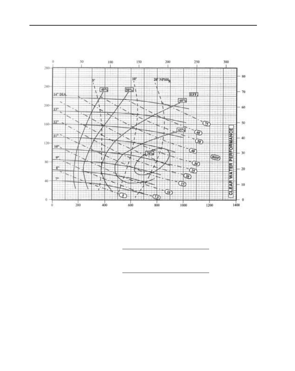
5 X 4 X 14 IN. - 1750 RPM
Calculating horsepower using efficiency:
Maximum Sphere - 13/32 in.
BHP =
GPM x FT x SG
3960 x Efficiency
kW =
M
3
/hr x M x SG
367 x Efficiency
Cubic Meters per Hour
(M
3
/hr)
T
o
ta
l Diff
erent
ial Head
(F
eet)
Tot
al Dif
ferent
ial Head
(Met
ers)
US Gallons per Minute (GPM)
PUMP CURVES
Baker SPD
20
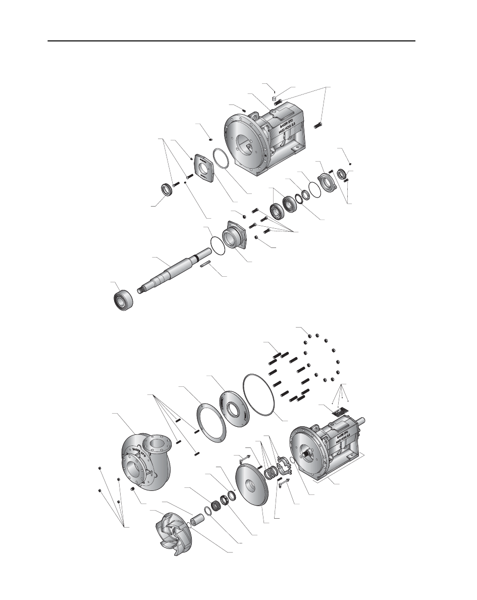
PRODUCT ILLUSTRATIONS FOR SIZE 5 X 4 X 14 IN.
2.5 IN. CENTRIFUGAL PUMP
3
1
4
4
23
22
24
19
17
9
7
15
20
21
10
12
16
6
7
5
8
11
14
15
13
18
2
25
34
33
31
30
37
26
35
27
38b
38d
47
45
999881
40
41
39
38c
36
29
28
40
41
42
43
32
46
44
38a
PRODUCT ILLUSTRATIONS

Baker SPD
21
PARTS AND WEIGHTS (SIZE 5 X 4 X 14 IN.)
Item
No.
Description
5 x 4 x 14 in.
1
Frame
052136610
Gray Cast Iron
250.0 lb
2
Plastic Plug
WVCCCF118
Plastic
.01 oz
3
Plug for Breather Port
WWWX00011
Carbon Steel
.02 oz
4
Oil Plug
WWWX00012
Carbon Steel
(2 required)
.05 oz
5!!
Outboard Bearing Labyrinth Seal
WVIN00262
Bronze
.80 oz
6
Outboard Bearing Cover
052136910
Gray Cast Iron
3.0 lb
7
Outboard/Inboard Bearing Grease Fitting
WWW00C003
Steel
(2 required)
.10 oz
8
Outboard Bearing Cover Bolt
WWG31D107
Low Alloy Steel
(2 required)
2.0 lb
9!!
Outboard Bearing Housing Seal
WWB254P41
Buna-N
.10 oz
10
Outboard Bearing
WWESK7311
Steel
(2 required)
3.08 lb
11!!
Bearing Lock Washer
WV00W1100
Carbon Steel
.50 oz
12!!
Bearing Lock Nut
WV00N1100
Carbon Steel
.50 oz
13
Outboard Bearing Housing
052136810
Gray Cast Iron
15.0 lb
14
Outboard Bearing Housing Bolt
WWG31H1H7
Low Alloy Steel
(4 required)
.50 oz
15
Outboard Bearing Housing Nut
WWJ31H800
Stainless Steel
(2 required)
.50 oz
16!!
Outboard Bearing Cover Seal
WWB248P41
Buna-N
.01 oz
17
Shaft
052133900
Low Alloy Steel
37.75 lb
18
Coupling End Key
WWW00A004
Low Alloy Steel
2.0 lb
19
Inboard Bearing
WWENT5313
Steel
8.71 lb
20
Inboard Bearing Cover
052136710
Gray Cast Iron
10.00 lb
21!!
Inboard Bearing Cover Gasket
052137400
Fiber
.01 oz
22
Inboard Bearing Cover Bolt
WWG31H1H7
Low Alloy Steel
(2 required)
.50 oz
23
Inboard Bearing Cover Grease Plug
WWWX00011
Carbon Steel
.02 oz
24!!
Inboard Bearing Labyrinth Seal
WVINM0026
Bronze
1.0 lb
25
Jack Bolt
WWG31S28F
Stainless Steel
(2 required)
.35 oz
26!!
Wear Pad Nut
WWJ51H800
Stainless Steel
(4 required)
.05 oz
27
Casing Drain Plug
WWWX00015
Carbon Steel
.15 oz
28!!
Casing
052134210
Gray Cast Iron
170.0 lb
29!!
Wear Pad Stud
WWHS1H28A
Low Alloy Steel
(4 required)
.10 oz
30!!
Wear Pad Gasket
052139001
Fiber
.01 oz
31!!
Wear Pad
052134810
Hard Iron
34.0 lb
32!!
Casing Gasket
052137100
Fiber
.10 oz
33!!
Casing Stud
WWHS1S3HA
Low Alloy Steel
(12 required)
1.0 lb
34!!
Casing Stud Nut
WWJ11S800
Stainless Steel
(12 required)
.10 oz
35
Impeller
05213591X !
Hard Iron
41.0 lb
36!!
Impeller Seal
WWB032V30
Fluoroelastomer
.001 oz
37!!
Shaft Sleeve
052137080
Stainless Steel (Ceramic Coated Material No. 052144280)
2.1 lb
38a -
38d
Mechanical Seal Kit,
(Includes - Pressed Ring Spring, Rotating Element,
Stationary Element and item 47 Roll Pin)
WVBUF9000
2.35 lb
Stainless Steel/Tungston Carbide/Fluoroelastomer
39
Stuffing Box Cover for Mechanical Seal
052136410
Hard Iron
70.0 lb
40
Gland Assembly Bolt
052137280
Stainless Steel
(2 required)
2.0 lb
41
Stuffing Box Cover Bolt
WWG31H187
Low Alloy Steel
(2 required)
1.0 lb
42
Packing, 3 Rings for Mechanical Seal
052141500
Teflon/Graphite
3.0 lb
43
Gland Set
052136500
Stainless Steel
3.0 lb
44!!
Shaft Sleeve Seal
WWB225V40
Fluoroelastomer
.10 oz
45
Name Plate
052141400
Stainless Steel
.10 oz
46
Drive Screws
WWGT06060
Stainless Steel
(4 required)
.01 oz
47
Roll Pin
WWL1040HS
Steel
.01 oz
! Last digit (x) designates Impeller size. See sizing chart on page 11.
!! Refer to pages 12 and 13 for Repair Kit information.
PARTS AND WEIGHTS
O
RD
E
R
IN
G
I
NFOR
MAT
ION

2
TABLE OF CONTENTS
Introduction ---------------------------------------------------------------------------- 5
General Instructions ------------------------------------------------------------------ 5
Section A: INSTALLATION-------------------------------------------------------- 5
Compatibility ------------------------------------------------------------------------------------5
Location ------------------------------------------------------------------------------------------5
Foundation ---------------------------------------------------------------------------------------5
Alignment ----------------------------------------------------------------------------------------6
Piping---------------------------------------------------------------------------------------------7
SECTION B: PREPARATION FOR OPERATION ----------------------------- 8
Preliminary Lubrication ------------------------------------------------------------------------8
Mechanical Seal Pumps ------------------------------------------------------------------------8
Packed Pumps -----------------------------------------------------------------------------------8
Pump Rotation-----------------------------------------------------------------------------------8
Pump Priming -----------------------------------------------------------------------------------8
SECTION C: OPERATION --------------------------------------------------------- 9
Operating Condition Envelope ----------------------------------------------------------------9
Documentation ----------------------------------------------------------------------------------9
Lubrication--------------------------------------------------------------------------------9
Grease Lubrication for Bearings ----------------------------------------------------- 10
Grease Lubrication for Packing ------------------------------------------------------ 10
Water Lubrication for Packing ------------------------------------------------------- 10
SECTION D: MAINTENANCE--------------------------------------------------- 10
Disassembly ----------------------------------------------------------------------------------- 10
Inspection -------------------------------------------------------------------------------------- 11
Assembly--------------------------------------------------------------------------------------- 12
Shaft and Bearing Sub-Assembly---------------------------------------------------- 12
Power Frame Sub-Assembly --------------------------------------------------------- 13
Stuffing Box and Components ------------------------------------------------------- 14
Fluid End Assembly ------------------------------------------------------------------- 15
General Operating and Storage Instructions----------------------------------------------- 15

3
TABLE OF FIGURES
Figure 1: Offset Alignment with a Dial Indicator .......................................... 6
Figure 2: Angular Alignment with a Dial Indicator ....................................... 6
Figure 3: Offset Alignment with a Straight edge ........................................... 7
Figure 4: Angular Alignment with a Straight edge ........................................ 7
Figure 5: Inboard bearing cover with grease fitting ..................................... 10
Figure 6-1 Casing and parts.......................................................................... 22
Figure 6-2: Frame, Stuffing Box Cover, Impeller and parts ........................ 22
Figure 6-3: Frame, Inboard Bearing Housing Cover and parts .................... 23
Figure 6-4: Shaft, Bearings and parts ........................................................... 23

4
TABLE OF TABLES
Table 1: Mud Hog Spare Parts List. ............................................................ 18
Table 2: Mud Hog Repair Kits .................................................................... 21

5
Introduction
This manual contains instructions
for the installation, operation and
maintenance of Baker SPD’s Mud Hog
2.5 Centrifugal Pump. After going
through this manual, if you feel that
some of your questions or situations that
you are dealing with, have not been
addressed, please contact your local
Baker SPD Distributor or Salesman for
further assistance.
Baker SPD’s Mud Hog 2.5 is a
pump designed to replace some older
and existing 2.5” pumps, with a similar
but superior product. We have designed
this pump keeping in mind a longer life,
reliability and easier maintenance. Some
of its outstanding features that contribute
towards its popularity and success are;
1. Pump casing with a replaceable wear
pad
2. Stainless steel shaft sleeves
3. Stainless steel casing nuts
4. Grease lubricated bearings
5. Leakage and contamination
prevention through labyrinth seals
It is very important to closely follow
proper installation, operation and
maintenance guidelines in order to
ensure a smooth and efficient pumping
operation and a longer equipment life.
General Instructions
1. The motor/driver must operate the
pump in a manner that the rotation of
the pump impeller when viewed
from the suction (front) side of the
pump is COUNTER-CLOCKWISE.
The pump must not be operated in
the reverse direction if damage to the
pump is to be avoided.
2. The suction and discharge valves
must not be completely closed when
operating the pump.
3. The packing should be adjusted in a
manner that a small amount of
leakage remains for lubrication and
cooling purposes.
4. For drilling mud operations, care
must be taken to prevent seepage
from the packing to dry out and
coagulate in the areas of the front
seal and the slinger.
5. Do not operate the pump outside its
designed performance envelope.
Section A: INSTALLATION
Compatibility
The Mud Hog 2.5 has been designed
to ensure that it can replace existing
pumps of the same nominal size. To this
end, its outside dimensions are
guaranteed to match up to the existing
bases, piping, couplings etc.
Location
To eliminate the need for priming,
the pump suction should be at a lower
level than the level of the liquid in the
supply tank/reservoir.
Foundation
It is recommended to pour a concrete
foundation on a solid base and it should
be big enough to support the whole
pump unit. The rigidity of the base plate
will play an important role in damping
out structural vibrations so the
foundation must be thick enough to
accomplish that. Refer to Hydraulic
Institute’s Standard ANSI/HI 1.4-2000
for guidelines on this subject. Care must
be taken to level the base plate in a
horizontal position. Also, when the
6
application dictates the use of fabricated
bases, the foundation design must
account for it properly, so that it can
effectively dampen the resulting
resonant vibrations.
Alignment
For any rotating machinery, the
alignment of power transmitting and
power consuming parts is critical for its
safe and long lasting service. Even if the
motor and the pump were aligned
before shipping, it is very important to
check the alignment after installation to
ensure that the arrangement has not
moved during transportation or
handling. We cannot overemphasize
proper alignment since it can mean the
difference between a smooth and long
lasting pump operation as opposed to
high vibrations and even failure of
bearings, coupling, pump or the motor.
It should be noted that one must not try
to align the pump and the motor until
its flange and mounting bolts have been
tightened.
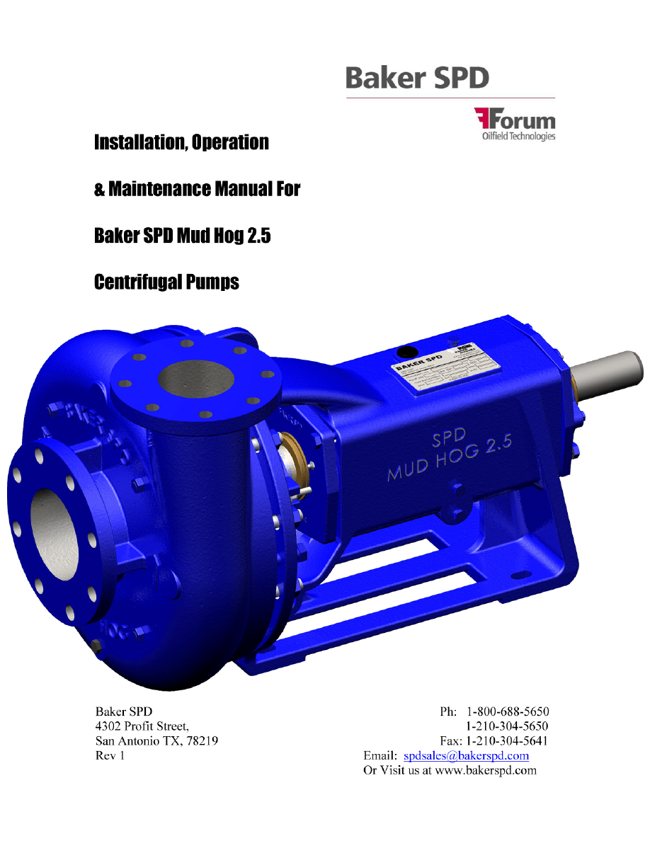
To perform the coupling alignment
with dial indicators, which are the
instruments of choice for such
procedures, the dial indicator is attached
to one coupling half with the indicator
dial button resting on the outside
diameter (OD) of the other coupling half.
This will give the offset misalignment
between the two shafts. In order to find
out the angular misalignment, let the dial
indicator button ride on the face of the
other coupling half, instead of its OD. A
TIR of 0.005” or less is usually
considered acceptable by most
manufacturers. If the TIR is more than
that, it can be adjusted by loosening the
pump or driver mounting bolts, adding
or removing shims accordingly and then
tightening down the bolts again
.
See
Figures 1 & 2 below.
Figure 1: Offset Alignment with a Dial Indicator
Figure 2: Angular Alignment with a Dial
Indicator
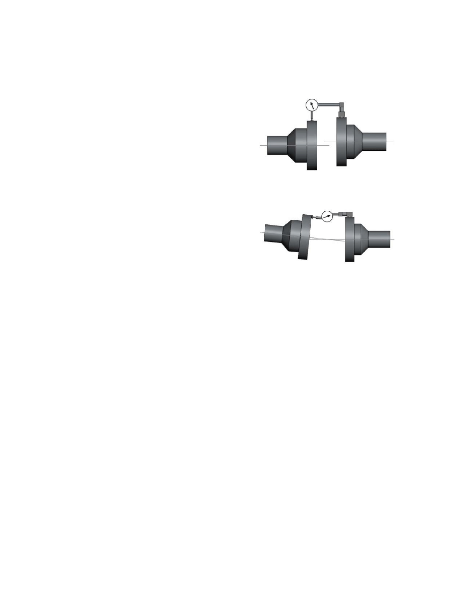
For situations where a dial indicator
is not available, one can use a straight
edge to perform a reasonable alignment.
This method works better when the
coupling has a rubber or a flexible drive
element.
To check for offset misalignment,
place the straight edge on the OD of the
couplings. If they are aligned there will
not be any gaps under the straight edge.
A max gap of 1/64” is allowed. This
procedure should be repeated for at least
one more location on the circumference
of the coupling 90 degrees from the first
position.
To check for angular misalignment,
the two coupling mating faces should not
have a variation in the gap, all around
the faces. A maximum variation of 1/64”
is permissible.
7
See figures 3 & 4 below.
Figure 3: Offset Alignment with a Straight edge
Figure 4: Angular Alignment with a Straight
edge
More information on coupling alignment
can be found in the Hydraulic Institute’s
Standard ANSI/HI 1.4-2000.
Piping
It is important that the piping should
line up to the pump without it having to
be drawn closer by tightening the
companion flange bolts. Also, the pump
should not have to support the weight of
the piping. For this to happen, it is better
to have the piping anchored
independently but as close to the pump
as possible. It should also be pointed out
that the piping should not be connected
to the pump until the grout has hardened
and after the motor and pump mounting
bolts have been tightened.
Suction Piping
Suction piping can not only play a
critical role in causing vibration and
cavitation in centrifugal pumps, but can
also be responsible for causing packing
and mechanical seal failures as well as
putting extreme loads on the bearings. It
is therefore very important that the size
of the suction piping be at least the same
or larger than the suction port of the
pump.
To eliminate air pockets in the
suction line, it is beneficial for the
suction line have a gradual slope down
to the supply tank or source.
It is recommended that the flow
through the pump should not be
controlled by adjusting a valve in the
suction line. However, this does not
preclude the use of a suction line shut off
valve to be used when the pump has to
be inspected or removed for
maintenance purposes.
In order to have a relatively
turbulence free flow into the pump, it is
good practice to have a straight length of
pipe, at least twice its diameter in length
e.g. a 6 inch suction pipe should have at
least one foot of straight pipe just before
the pump.
In situations which might require a
flexible hose to be used in the suction
line, it is imperative that such a flexible
hose be of the non-collapsing type, since
it is not uncommon to have suction
pressures which are below atmospheric
pressure. In such a scenario, there is a
real possibility of starving the pump and
thus causing it to overheat.
Discharge Piping
Like the suction piping, a shut off
valve should be used in the discharge
piping as well, to enable the removal of
the pump for maintenance purposes. A
throttle valve can be used in the
discharge line to operate the pump at it is
design point, if the exact operating
conditions are not known.
In case of a closed pressurized loop,
it is necessary to have a check valve

8
between the pump and the throttle valve,
to prevent the product from flowing back
through the pump. In the absence of the
check valve, such a circumstance can
cause the impeller to come loose and
cause damage to the pump and also
result in leakage beneath the shaft sleeve.
SECTION B:
PREPARATION FOR
OPERATION
Before starting the pump, it is good
practice to always go through the
following simple checks;
1. Check for impeller’s free rotation by
turning the shaft by hand
2. Make sure that the suction line and
the pump are full of fluid and that the
suction valve is fully open.
3. Slightly open the discharge valve
and then open it fully once the pump
is running.
Preliminary Lubrication
Our standard pumps come pre
lubricated with grease (oil lubrication is
available as an option). The operators /
customers do not have to worry about
lubricating the pump for the first year of
operation. At that time, the pump can be
lubricated through the outboard and
inboard bearing covers by removing the
plugs and replacing them with the
appropriate lubrication fittings.
Usually, labyrinth seals are provided
at both bearing ends, and they serve to
keep the temperature from rising, by also
acting as vents. But in cases where the
labyrinth seals are not provided, it is
recommended to keep the air vent clean.
Mechanical Seal Pumps
It is vital that these pumps are never
started dry otherwise it will cause
irreparable damage to the seal faces. The
factory installs and adjusts the
mechanical seals before shipping the
pumps. The seal models currently being
provided with the Mud Hog 2.5 do not
require external flush.
Pumps with mechanical seals come
with 3 rings of backup packing which
should be kept completely loose until a
seal failure occurs. Only then should
they be tightened down to prevent
leakage.
Packed Pumps
When starting packed pumps, the
packing should be loose and the packing
gland nuts should only be hand tight.
Once the pump starts running, slowly
tighten the packing down. Make sure
that there is some leakage through the
packing, otherwise it will overheat and
fail.
If outside flushing is required on
either pump models, the flush lines
should be connected and checked for
flow through them, before starting the
pump
Pump Rotation
Before running the pump it is
important to find out the direction of
rotation, since starting the Mud Hog 2.5
in the reverse direction can unscrew its
impeller and thereby cause damage to
the pump and the seal.
The direction of rotation can be
checked in two ways. The motor can be
uncoupled from the pump and then
started to check its direction of rotation.
Or a person can start and immediately
shut off the coupled motor and pump
assembly and have someone else watch
as the shafting just turns over.
Pump Priming
To prevent damage to the
mechanical seals or packing, there must

9
be liquid in the suction line and the
casing, before the pump is started. Fill
the suction line with the liquid and vent
out any air that might be present in the
line. The discharge valve should be
barely open when the pump is started
and only after the flow and pressure
have stabilized that it should be adjusted
to the required flow conditions. If the
pressure fails to build, close the
discharge valve and then reopen it to
build discharge pressure. If flow
difficulties continue, it may be an
indication of improper installation or
pump selection.
Operators must not run the pump
with the suction valve closed under any
circumstances, as it will immediately
overheat the pump and cause major
damage to various components.
Also, running the pump with the
discharge valve closed should be
allowed only for short durations as the
energy being imparted to the pumped
product by the impeller, will raise the
temperature. If for some reason there is a
need to keep the discharge valve closed
for an extended length of time, then it is
recommended to run a small (
Ø
0.25”or
Ø
0.50”) line, starting between the pump
and the discharge valve and going back
to the fluid supply tank.
SECTION C: OPERATION
Operating Condition Envelope
This section only applies to pumps
which do not have any external
insulation and are exposed to the room
temperature.
The maximum safe working pressure
for cast iron is 175 psig at 150°F or 150
psig at 250°F. The conditions in between
can be accordingly calculated. Whenever
a high temperature (150°F plus) fluid is
being pumped, cooling water should be
passed not only through the lantern ring
but also over the exposed shaft, so as to
dissipate the heat being generated at the
labyrinth seal or lip seal and the bearings.
Documentation
It is always helpful to maintain a
documentation history of the pump as it
can improve our response time to help
you. To this end, we provide a
nameplate on each pump frame which
contains some information which can
help us identify the pump quickly. But in
addition to that, it would be helpful to
keep a record of the following
information;
1. Motor horsepower
2. Operation frequency
3. Maintenance records and pertinent
information on any replacement parts.
Lubrication
Your Mud Hog comes lubricated
with grease when it is shipped from the
factory and it does not need to be
lubricated more than once per year. The
recommended grease is Lubri Plate
1200-2. When using different types of
grease, care should be taken to use only
those types of grease which are well
suited to operate with each other.
Oil Lubrication for Bearings
Oil lubrication for bearings is
available as an option but the pumps
must be mounted in a horizontal position
for oil lubricated pumps to work. This
option is typically exercised when it is
desired to lower the bearing temperature
and hence reduce its wear.
It is recommended to use 10W30-
non detergent motor oil. The oil can be
filled through the hole provided on the
top of the bearing frame. After removing
the plug provided in the side of the
frame, oil should be added from the top
10
until it starts to flow out from the side
hole. This will indicate that the level of
oil is correct. Adding more oil than
recommended can actually be harmful to
the pump.
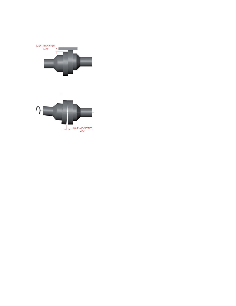
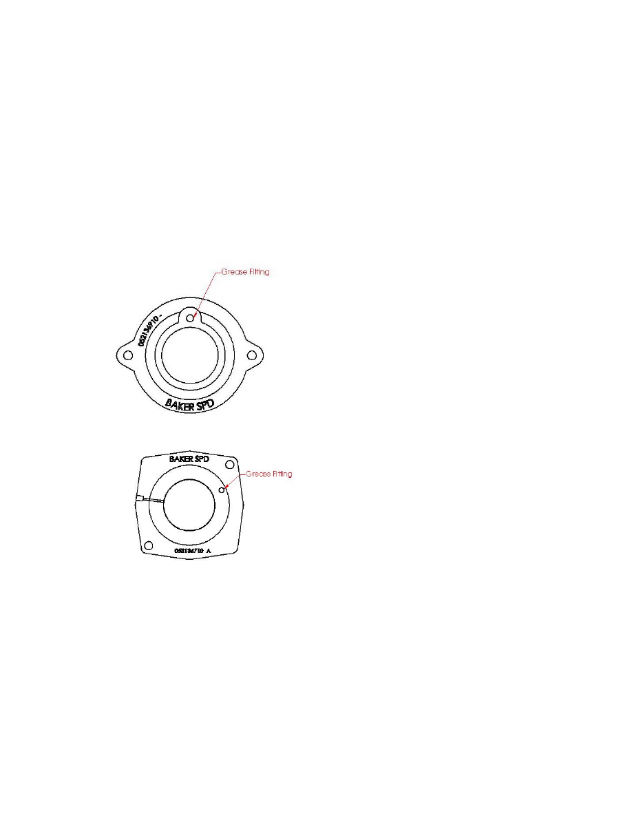
Grease Lubrication for Bearings
The outboard and inboard bearing
covers are provided with a grease fitting.
It is recommended to add five shots of
grease through the grease port at least
once every six months, after the first
year of service.
Figure 5: Outboard and Inboard bearing covers
with grease fitting
Grease Lubrication for Packing
For packed pumps, the stuffing box
cover comes with a drilled hole for
lubricating the packing rings. It is fitted
with a grease fitting. It is recommended
to lubricate the packing rings at least
once a day. Baker SPD offers an
optional self lubricating mechanism
which only needs to be filled from time
to time.
Grease should be added while
turning the shaft. A good indication of
the sufficient grease in the packing is
that it will start to come out around the
packing gland. If the packing rings are
worn and/or the leakage is deemed
excessive, a more viscous variety of
grease like the ones used in water pumps
should be used rather than the general
purpose grease.
Water Lubrication for Packing
It is recommended that whenever
drilling mud is being pumped, water
should be fed to the packing through the
lantern ring, not only for lubrication
purposes but also to prevent fluid being
pumped from coming through the
packing rings. Such fluids can reduce the
life of the packing as well as cause
abrasion of the shaft.
SECTION D:
MAINTENANCE
Refer to Figure 6-1 through 6-4.
Disassembly
1. Remove the packing gland
halves (43) by loosening the
packing gland nuts (41) and then
swinging the packing gland bolts
(40) to the side.
2. Remove the casing (28) after
removing the casing nuts (34).
3. Impeller (35) can now be
removed as follows;
Restrain the shaft rotation near
the coupling end and then jam a
block of wood against the
impeller vanes. Strike the block
of wood with a hammer to turn
the impeller in the counter
clockwise direction, when

11
looking at the pump from the
suction end.
4. The stuffing box cover (39) does
not need to come off if the
mechanical seal does not warrant
a replacement. However, if it
does, then remove the stuffing
box cover bolts (41) and push out
the stuffing box cover (39) by
hitting on its back side. The
packing rings (42) can now be
easily removed from the stuffing
box bore.
5. The next step is to slide off the
shaft sleeve (37), with the help of
a wedge, if needed, and taking
care not to damage or drop the
seal, especially if the seal does
not need to be replaced. If the
only repair being done is the
mechanical seal replacement then
this is as far as you need to go in
disassembling the pump.
6. The two bolts (14) holding the
outboard bearing housing (13) to
the frame (1) should be removed.
7. The shaft/bearing assembly can
now be removed from the frame.
8. Take out the outboard bearing
housing cover (6).
9. The locknut (12) and the lock
washer (11) can be removed by
bending the tab backwards on the
lock washer.
10. Remove the Outboard bearing
Housing (13). The outboard
bearings (10) can be pressed off
the shaft (17) by hitting the key
end of the shaft against a wooden
floorboard. Similarly, the
inboard bearing (19) can be
forced off the shaft (17) by
hitting its inner race with a pipe
of an appropriate size. Applying
force against the outer race of the
bearings should be avoided.
11. The inboard bearing labyrinth
seal (24) and the inboard bearing
cover grease plug (23) can be
now removed.
Inspection
In general, whenever disassembling a
pump, always clean the retaining rings,
grooves for the O-rings, surfaces of the
gaskets, threads and bearings.
Impeller: The impeller should be
checked for excessive erosion both on
the front and back vanes and/or vane
breakage and replaced if any of the
mentioned conditions exist.
Shaft and Shaft Sleeve: A maximum
run out of 0.002 is allowed on the shaft
and the shaft threads must be in a good
condition. The bearing seating surfaces
have to be smooth and free of scratches.
If any of the above do not seem to be in
good condition, the shaft should be
replaced. Similarly the surface of the
sleeve should be checked for grooves
and be replaced if necessary.
Mechanical Seal: To prevent
excessive leakage, the seal faces, gaskets
and shaft sealing members must be
checked for their condition and replaced
if necessary.
Ball Bearings: It is important that the
bearings rolling elements be smooth and
not worn out. If the bearings make noise
when rotated, it is time to replace them.
New bearings should not be unpacked
until it is time to install them.
Gaskets & O-Rings: Short of
unavailability of new ones, it is always
good practice to replace all the gaskets
and O-rings during disassembly.

12
Assembly
Refer to Figure 6-1 through 6-4.
Shaft and Bearing Sub-Assembly
Note: Installation of the bearings with a
press is acceptable in lieu of heating the
bearings.
1. Pack the inboard bearing (19)
and both outboard bearings (10)
with Chevron Duralith EP No. 2
or Lubriplate 1200-2 grease.
Heat the inboard bearing (19)
and the two outboard bearings
(10) to 240° F max.
2. After heating the inboard
bearing (19), position it to be
installed. Check to see if the
marking "5313" is on the bearing.
Slip the bearing onto the impeller
end of the shaft (17). Shoulder
the bearing.
3. Install the outboard bearing
housing seal (9) onto the
outboard bearing housing (13).
Slide the outboard bearing
housing (13) onto the shaft (17)
from the coupling end of the
shaft. The flanged end of the
outboard bearing housing (13)
should face the coupling end of
the shaft (17).
4. After heating one of the outboard
bearings (10), position it to be
installed. Slip the bearing onto
the shaft (17) with the "7311"
marking facing the coupling end
of the shaft (17). Shoulder the
bearing.
5. After heating the other outboard
bearing (10), position it to be
installed. Slip the bearing onto
the shaft (17) with the "7311"
marking on this bearing, facing
the “7311” marking on the
previously installed bearing and
shoulder the bearing. This
bearing arrangement is called a
"Back-to-back" installation.
6. Check for proper outboard
bearing (10) installation. The
"7311" markings on both
outboard bearings (10) should be
facing each other. The balls and
races on both bearings should be
clearly visible.
7. Install the bearing lock washer
(11) onto the shaft (17) with the
tabs towards the driven end of
the shaft (17).
8. Install the bearing locknut (12)
onto the shaft (17) with the bevel
towards the bearing lock washer
(11). Tighten the bearing locknut
(12) with 250 ft/lb of torque.
Bend one tab of the bearing lock
washer (11) to engage one cutout
of the bearing locknut (12).
Note: If the tab on the bearing
lock washer (11) does not align
with a slot directly, loosen the
bearing locknut (12) until the
closest tab/slot combination is
aligned.
9. Lightly grease the outboard
bearing (10) outside diameters.
Shoulder the outboard bearing
housing (13) to the outboard
bearings (10).
10. Install the outboard / inboard
bearing grease fitting (7) into the
outboard bearing cover (6) with
the nipple facing towards the
outside of the outboard bearing
cover (6). Press the outboard
bearing labyrinth seal (5) with
drain cutout down or rotated
180° from the 1/4" NPT hole in
the outboard bearing cover (6)
and with the drain on the inside
of the outboard bearing cover (6).

13
11. Apply grease to the shaft (17).
Assemble the outboard bearing
cover (6) to the outboard bearing
housing (13). Install the outboard
bearing cover bolts (8) and
torque to 20 ft-lbs.
Caution: Do not over tighten the
outboard bearing cover bolts (8).
There will be a gap between the
outboard bearing housing (13)
and the outboard bearing cover
(6) with proper installation (.015-
.030 in.).
Power Frame Sub-Assembly
1. Install the outboard / inboard
bearing grease fitting (7) into the
inboard bearing housing (20).
Press the inboard bearing
labyrinth seal (24) with drain
cutout down, 180° from the cast
Baker SPD logo and to the inside,
into the inboard bearing housing
(20). Install the inboard bearing
cover grease plug (23) into the
inboard bearing housing (20).
Place the inboard bearing cover
gasket (21) onto the inboard
bearing cover (20)
2. Install the inboard bearing cover
(20) into the frame (1) with the
cast Baker SPD logo up. Install
the inboard bearing cover bolts
(22) into the frame (1). Stop
when two threads of each bolt are
still exposed.
Note: Do not tighten the bolts at
this time.
3. Lightly grease the outboard
bearing housing bore and inboard
bearing bores in the frame (1).
Install the 'shaft / bearing sub-
assembly' from the previous
section into the frame (1). Leave
1/4" between the outboard
bearing housing (13) flange and
the frame (1).
4. Install two outboard bearing
housing nuts (15) onto two
outboard bearing housing bolts
(14). Thread the outboard
bearing housing bolts (14) /
outboard bearing housing nuts
(15) into the outboard bearing
housing (13) and hand tighten.
Thread two outboard bearing
housing bolts (14) through the
outboard bearing housing (13)
and into the frame (1) and hand
tighten.
5. Torque the inboard bearing
cover bolts (22) to 20 ft-lbs.
Note: There will be a gap
between the inboard bearing
cover (20) and the frame (1) after
proper installation (.015-.030)
6. Install two oil plugs (4), the plug
for the breather port (3), and the
plastic plug (2) into the frame (1).
Install the jack bolts (25) into the
frame (1).

14
Stuffing Box and Components
Mechanical Seal Configuration
1. Install the roll pin (47) into the
stuffing box cover (39) from the
impeller side.
2. Install the stationary element
(38d) into the stuffing box cover
(39). Align the slot on the
stationary element (38d) with the
roll pin (47). Bottom the
stationary element (38d).
Caution: Do not scratch or
damage stationary element (38d)
sealing surface; keep the sealing
surface clean.
3. Grease the 3-ring packing set
(42). Install the 3-ring packing
set (42) and the shaft sleeve (37)
into the stuffing box cover (39)
bore by installing each of the
three rings with the skive 180°
apart.
4. Install the gland assembly bolts
(40) into the stuffing box cover
(39) and torque to 20 ft-lbs.
Packing Ring Configuration
1. The packing rings (42) will
usually be either of the Teflon or
King type.
2. Make sure that the shaft sleeve
OD and the stuffing box cover ID
are clean, smooth and free of any
burrs and scratches.
3. Grease should be applied to all
the packing rings.
4. Insert three packing rings, taking
care to align skives in the rings
180 degree apart and the skive on
the first ring on the bottom side.
In case of King packing, install
the rings such that their lips are
facing the suction side of the
pump.
5. The lantern ring should be
installed next, making sure that
the split in the lantern ring is
oriented vertically.
6. The remaining two rings should
now be installed such that the
skive in the last ring comes on
the bottom side. However, in
case of King Packing, the final
King ring should be mounted
such that the lip is facing the
coupling end and it’s skive at the
top. The last square ring of
packing can then be installed
with the skive pointing
downwards.
7. The packing gland halves (43)
should now be put it place and
pressed in slightly by tightening
the gland assembly bolts (40).
Note: Since packing can burn
easily if it is too tight around the
rotating element, so once the
packing has been pushed and
seated in, the gland assembly
bolts (40) can be loosened and
then hand tightened only. This is
the recommended condition to
start the pump in. Once the pump
has been running for a little while,
one should go back in and tighten
the gland assembly bolts (40) so
that there is only 10-15 drops of
leakage per minute.

15
Fluid End Assembly
1. Slip shaft sleeve seal (44) onto
the shaft (17) and shoulder.
2. Coat the stuffing box bore in the
frame (1) with Baker Seal
compound. Install the stuffing
box cover (39) into the frame (1)
with the word 'Top' towards the
lifting eye or up. Install the
stuffing box cover bolts (41) and
fully tighten to 50 ft-lbs.
3. Apply a coat of grease to the
shaft sleeve (37), to the inside of
the rubber bellows and to the
sealing face of the rotating
element (38c). Slip the rotating
element (38c) onto the shaft
sleeve (37) and contact the
stationary ring (38d). Slip the
spring (38b) onto the shaft sleeve
(37). Install the pressed ring
(38a) onto the spring (38b).
4. Grease the impeller seal groove
on the impeller (35). Place the
impeller seal (36) into the
impeller groove in the impeller
(35). Screw the impeller (35)
onto the shaft (17) and torque to
a minimum of 160 ft-lb.
Note: Align the spring (38b) on
the rotating element (38c) and
the impeller (35).
5. Install one gland set (43). Snug
the gland set (43) against the 3-
ring packing (42) and back off to
a hand tight condition.
6. Set the clearance between the
stuffing box cover (39) and the
impeller (35) to 0.070" – 0.075”
by adjusting the outboard
bearing housing bolts (14).
Tighten the outboard bearing
housing nuts (15).
Caution: ensure that the impeller
turns freely. Torque the
remaining two outboard bearing
bolts (14) to 20 ft-lbs.
7. Note: This step not required with
3 X 2 casings. Install wear pad
studs (29) into the wear pad (31).
Slip wear pad gasket (30) onto
wear pad (31). Install wear pad
(31) into the casing (28). Install
the wear pad nuts (26) onto the
wear pad studs (29) and torque to
20 ft-lbs.
8. Install the casing studs (33) into
casing (28). Install the casing
gasket (32) onto the stuffing box
cover (39). Apply Baker Seal
compound to the two locating
surfaces on the stuffing box cover
(39). Install the casing (28) onto
the stuffing box cover (39).
Install casing stud nuts (34) onto
the casing studs (33) and evenly
torque to 140 ft-lb.
9. Install casing drain plug (27)
into the casing (28).
General Operating and Storage
Instructions
Some of the important factors to watch
for, while operating a pump, are;
1. The packing should not be over
tightened as it will become hard
and brittle and will fail to
perform its function. But it is
also important, especially when a
water flush system is being
employed to lubricate the
packing rings, that rings be not
too loose. That can result in flush
water seeping into the drilling
mud and changing its density.
This situation can also arise due
to a gap between the shaft and
the packing, which results due to
the whirling of the shaft about its
Wyszukiwarka
Podobne podstrony:
MUD PUMP 2
MUD PUMP
18 Series Tandem Pump Exploded View
Bosch Motorsport com HDP 5 Fuel Pump
130 cc Pump Service Parts
Mississippi Mud
Eaton Series 1 Model 33 64 Variable Pump Parts
JETTING PUMP 2
Chronomodulated infusion pump, materiały z neta
18 Series Variable Pump Exploded View
LIQUID MUD AGITATORS
55 cc Pump Service Parts
Popular Mechanics Replacing a Bad Power Steering Pump
Dynapower Gen II 12 0cu Pump Motor Var Mtr & Pump Valve Parts
Dynapower Gen II 9 0cu Pump Motor Var Mtr & Pump Valve Parts
#78 PUMP & PUMP OPERATION
Popular Mechanics Replacing Your Water Pump
więcej podobnych podstron