The automatic filters, T150, T280 and X280, are designed
specifically for full-flow filtering of lubricating oils for trunk
piston and crosshead engines.
Unique features
• Robust disc-type filter elements.
• Continuous backflushing.
• Filtered oil drives the backflushing process.
• Constant pressure drop across the filter.
• Compact and space-saving design.
Key benefits
• Robust design reduces risk of filter element cracking.
• Continuous backflushing significantly prevents adhesion
of retained solids to filter surfaces, which results in:
– No manual cleaning of filter elements.
– Low and constant pressure drop across the filter
elements, which further reduces the risk of cracking.
• Robust filter elements and continuous backflushing ensure
safe protection of the diesel engine, with normally more
than 12,000 operating hours between cleaning and inspec-
tion of the filters.
• Use of filtered oil for backflushing process eliminates the
need for external power supply and compressed air.
• Constant pressure drop across the filter, combined with the
pressure drop indicator, facilitates detection of malfunctions
in the lubricating oil system.
• Easy to install and to retrofit as an upgrade to existing
installations.
Lubricating oil filter: Protector X280.
Lubricating oil filter
Continuously automatic backflushing lubricating oil filter
Diesel engine protection
The filter is installed in the full-flow system as close to the
engine as possible to prevent harmful solid particles entering
the sensitive parts of the engine.
The separator is installed in the bypass system. Its function
is to remove harmful contaminants (solid particles and water)
from the lubricating oil system.
Design
The filter elements are assembled into a disc stack. The filter
elements comprise a filter frame and filter screen, and are
divided into sections by ribs.
The discs, with sleeve, guide rods, springs and flanges, are
mounted over the distributor to form the filtering unit. The
sections, divided by the ribs, form twelve independent filtering
columns.
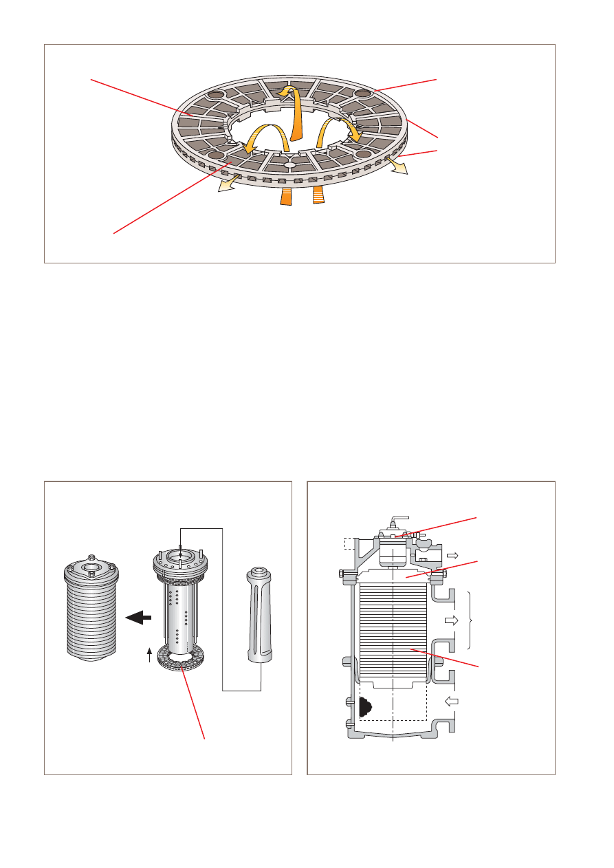
Figure 2. Filtering unit.
Figure 3. Fully assembled filter showing filtering unit and
hydraulic motor.
Figure 1. Full-flow element: Flow direction through one filtering element (Filtration).
Hydraulic motor
Filtering unit
Full-flow chamber
Full-flow filter
elements
Distributor
Filter elements
Rib
Filter screen
Filter frame
Upper half
Lower half
Filter element
}
Operating principle
The unfiltered oil entering the filter is fed by the distributor
to 11 of the 12 filtering columns. Solids are collected on the
filter surface and the filtered oil flows to the engine. Previously
collected solids are removed in the twelfth column by back-
flushing with a small amount of the filtered oil. This is taken
through a passage in the distributor via the backflushed oil
outlet and back to the lubricating oil sump.
The distributor, which is driven by the hydraulic motor on
top of the filter housing, rotates at regular intervals to feed
oil for filtration in 11 columns and to backflush in the twelfth.
In this way, all the columns are backflushed once per full
rotation of the distributor, which corresponds to every one
to three minutes.
The pressure drop indicator connected between the inlet
and outlet of the filter provides a reading and signals an
alarm condition if for any reason the pressure drop reaches
the alarm level. This indicates that there is a problem in the
lubricating oil system.
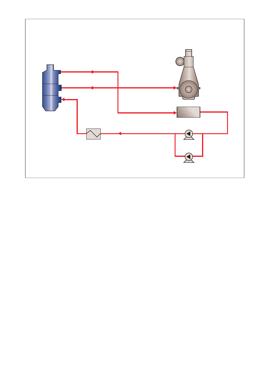
The driving force for the automatic backflushing is the
pressure difference between the clean oil outlet (P2) and
the backflushed oil outlet (P3) of the filter. A flow sheet
illustrating the pressures, flows and capacities is shown
in Figure 4.
A pressure drop indicator, inspection covers and counter
flanges are provided as ancillary equipment. Options exist for
additional features, such as magnetic plates installed on the
inlet housing.
Filter
P2
P3
Q3
QE
Diesel engine
QP
Lubricating oil sump
Stand-by pump
Note: When selecting filter Q1 must be > QP
QE = QP – 0.03 to 0.05 x Q1
P1
Q1
Pump
Figure 4. Protector automatic lubricating oil filter showing pressure, flow and capacity.
Key:
QP = Lubricating oil pump capacity
Q1 = Maximum capacity of the filter
QE = Lubricating oil flow to the engine
Q3 = Flow of backflushed oil
P2 = Clean oil outlet pressure
P3 = Backflushed oil outlet pressure
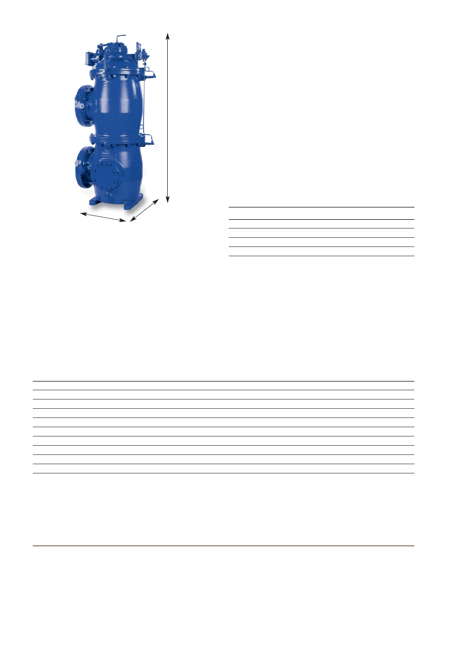
Guideline to overall dimensions
Depending on the surface area and number of filter elements
required for your application, the number of housings will vary,
and hence the overall size of the filter will be different.
Filtration fineness
This can be defined depending on diesel engine requirements
and the specific application.
Installation
All Alfa Laval automatic lubricating oil filters are designed for
installation in the engine room. Flanges are according to
DIN standards.
Other Alfa Laval filtration products
Alfa Laval also manufactures filters for other engine room
applications, such as automatic fuel oil filters, and manual
indicator and bypass filters.
After-sales support
Replacement components and after-sales services are
provided through a network of Alfa Laval subsidiaries and
representatives worldwide, including Marine Service Centres
in all major ports.
Dimensions
Lubricating oil flow (m
3
/h)
Height
×
Length
×
Width (mm)
Crosshead
Trunk piston
–150
20–80
750
×
450
×
450
150–300
80–200
1300
×
500
×
500
300–600
200–400
1300
×
1050
×
500
600–900
400–600
1300
×
1500
×
500
Technical documentation
Complete information and documentation for the main
components and the installation, operation and maintenance
of the filter is contained in the Instruction Book that accom-
panies delivery of each Alfa Laval filter. Your local Alfa Laval
company will be able to provide more details on the applica-
tion and sizing of Alfa Laval automatic filters.
How to contact Alfa Laval
Contact details for all countries are
continually updated on our web site.
Please visit www.alfalaval.com to
access the information direct.
EMD00047EN 0406
Alfa Laval reserves the right to change specifications without prior notification.
Technical data
Crosshead X280
Trunk piston T150, T280
Normal filter outlet pressure
2–3 bar (P2 norm)
3.5–6 bar (P2 norm)
Min. filter outlet pressure
1.4 bar
3 bar
Max. filter inlet pressure
12 bar
12 bar
Test pressure
24 bar
24 bar
Max. viscosity in filter at normal operation
130 cSt
75 cSt
Max. temperature in the filter
100°C
100°C
Alarm
∆
p
0.9 bar
0.8 bar
Backflushing flow
3% of filter inlet flow
3–5% of filter inlet flow
Housing material
Nodular cast iron
Nodular cast iron
Filter screen material
Stainless steel
Stainless steel
Length
Width
Height
Wyszukiwarka
Podobne podstrony:
file33576 0 EMD00046EN FO
file33576 0 EMD00046EN FO
file33833 0 EMD00049EN 0410 S Sep
IV LO
lo orm2 05 02 kp2
Art & Intentions (final seminar paper) Lo
lo orm1 16 06 kp1
lo zl 19c 04 kp
lo orm2 19 02 kp3
lo orm2 03 04 kp1
KATECHEZA LO.T.Czy mozna umawiac sie na spowiedz., KATECHEZA
Przebieg mobbingu – faza IV, LO, kurs pedagogiczny, patologie w pracy
Jezyk polski - zasady, LO, Jezyk polski
KATECHEZA do LO.T.SEKTY., KATECHEZA
stereometria, Szkoła-LO, MATEMATYKA
więcej podobnych podstron