The automatic filters are designed specifically for full-flow
filtering of fuel oils for trunk piston and crosshead engines.
Unique features
• Robust disc-type filter elements.
• Continuous backflushing driven by filtered oil.
• Constant pressure drop across the filter.
• Filtered oil drives the backflushing process.
• Compact and lightweight.
• Refiltration of backflushed oil and removal of particles
collected from the system at the filter.
Key benefits
• Robust design reduces risk of filter element cracking.
• Continuous backflushing significantly prevents adhesion
of retained solids to filter surfaces, which results in:
– No manual cleaning of filter elements.
– Low and constant pressure drop across the filter
elements, which further reduces the risk of cracking.
• Use of filtered oil for backflushing process eliminates the
need for compressed air.
• Constant pressure drop across the filter, combined with the
pressure drop indicator, facilitates detection of malfunction
in the fuel oil system.
• Easy to install and to retrofit as an upgrade to existing
installations.
Automatic fuel oil filter shown with electrical motor.
Fuel oil filter
Continuously automatic backflushing fuel oil filter
Diesel engine protection
The fuel oil conditioning system includes filters to remove
solid particles that may have entered the system after the
separator, which is installed in the cleaning system. The filter
hence prevents any potentially dangerous particles from
reaching the sensitive parts of the diesel engine fuel system.
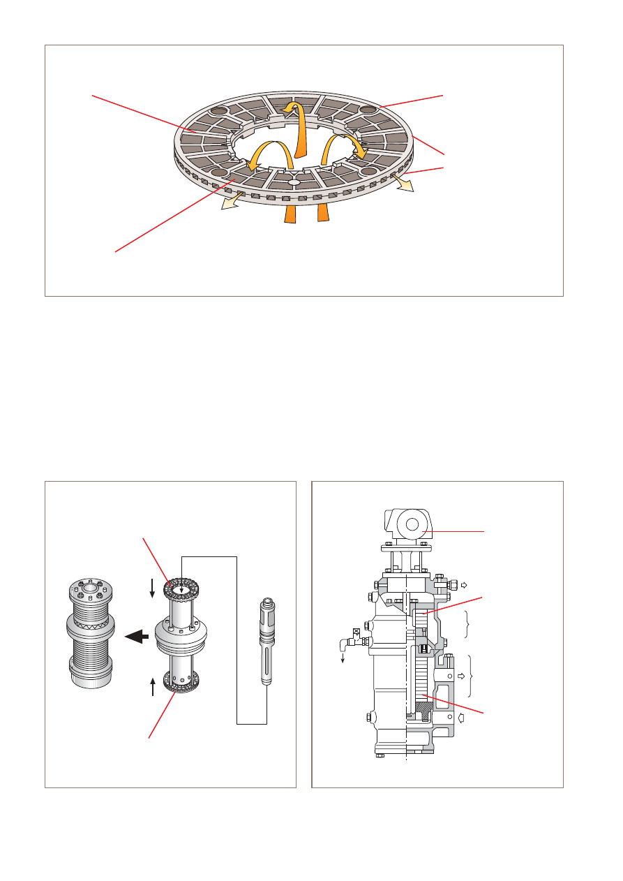
Distributor drive
The distributor, which creates the backflushing and self-
cleaning feature of the filter, is driven by either an electrical or
hydraulic motor. This selection will depend on your application
and the location of the fuel oil filter in the fuel oil conditioning
system. Above 120°C the electrical motor is mandatory and
standard on the Alfa Laval booster units.
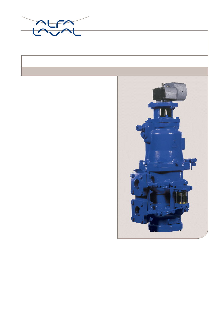
Figure 1. Full-flow element.
Figure 2. Filtering unit.
Figure 3. Fully assembled filter showing full-flow and diversion
chambers and electric motor.
Electric motor
Diversion filter
elements
Drain for
diversion
chamber
Diversion chamber
Full-flow chamber
Full-flow filter
elements
Diversion filter
elements
Distributor
Full-flow
elements
Rib
Filter screen
Filter frame
Upper half
Lower half
Filter element
}
Operating principle
The unfiltered oil entering the filter is fed by the distributor
to seven of the eight full-flow filtering columns. Solids are
collected on the filter surface and the filtered oil flows to the
engine. Solids previously collected are removed in the eighth
column by backflushing with a small amount of the filtered
oil and taken through a passage in the distributor to the
diversion chamber.
The distributor, which is driven by the hydraulic motor on
top of the filter housing, rotates regularly to feed oil for filtra-
tion in seven columns and backflushing in the eighth. In this
way, all the columns are backflushed once per full rotation
of the distributor which corresponds to every one to two
minutes.
The backflushed oil with solids entering the diversion
chamber is filtered in seven of the eight columns and led
back to the deaerator. At the same time backflushing by
clean oil takes place in the eighth column and solids settle
to the bottom of the diversion chamber, where they are
periodically discharged through the drain cock.
The pressure drop indicator is connected between the inlet
and outlet of the full-flow chamber. It provides a reading and
signals an alarm condition if, for any reason, the pressure
drop reaches the alarm level.
The driving force for the automatic backflushing is the differ-
ence in pressure between the clean-oil outlet (P2) and the
backflushed oil outlet (P3) of the filter. A flow sheet illustrating
the pressures, flow and capacity is shown in Figure 4.
A pressure drop indicator, drain cock and counter flanges are
provided as ancillary equipment. Options exist for additional
features, such as an automatic timer drain valve. In addition,
the Alfa Laval fuel oil filter is also available with a changeover
valve, and built-in bypass filter (see Figure 5). This allows un-
interrupted operation during routine maintenance.
Figure 5. Duplex automatic/manual fuel oil filter.
QCP
Filter
P2
QE
P3
Heater
Circ.
pump
Deaerator
Return from engine
Engine pressure
control valve
From diesel
engine
To diesel
engine
Drain
G3
P1
Q1
PD
=
P3
V21
Recommended for
certain engines
Figure 4. Protector automatic fuel oil filter, shown on the hot side of the booster module.
Key:
QCP = Circulation pump capacity
Q1
= Maximum capacity of the filter
QE
= Fuel oil flow to the engine
Q3
= Flow of backflushed cleaned oil
P1 = Filter inlet pressure
P2 = Filter outlet pressure
P3 = Backflushed oil outlet pressure
PD = Pressure in deaerator
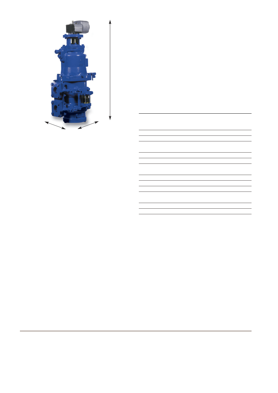
Guidelines to overall dimensions
For flow rates up to 20 m
3
/h:
Height
×
Length
×
Width (mm):
900
×
250
×
250
or with the built on bypass:
900
×
660
×
250
For flow rates from 20 to 30 m
3
/h:
Height
×
Length
×
Width (mm):
1620
×
500
×
450
or with the built on bypass:
1620
×
1130
×
450
Filtration fineness
This can be defined depending on diesel engine requirements
and the specific application.
Installation
All Alfa Laval automatic fuel oil filters are designed for
installation in the engine room. Flanges are according to
DIN standards.
The control of the electric motor of the fuel oil filter should be
installed on the booster module. When fitted with a hydraulic
motor, no external controller or energy supply is required.
Other Alfa Laval filtration products
Alfa Laval also manufactures filters for other engine room
applications, such as automatic filters both with and without
diversion chamber for lubricating oils, and manual indicator
and bypass filters.
After-sales support
Replacement components and after-sales service are
provided through a network of Alfa Laval subsidiaries and
representatives worldwide, including Marine Service Centres
in all major ports.
Technical data
Data
Value
Filter outlet pressure (P2)
– Min.
2 Bar above pressure (P3)
– Recommended
3–5 Bar above pressure (P3)
Max. filter inlet pressure (P1)
15 Bar
Test pressure
30 Bar
Max. viscosity in the filter
at normal operation (hot side)
75 cSt
Max. temperature in the filter
160°C
Alarm
∆
p (P1–P2)
0.8 Bar
Backflushing flow
15–20% of circulating
pump capacity (QCP)
Housing material
Nodular cast iron
Filter screen material
Stainless steel
Heating method
Steam/hot water/thermal oil
Supply
110/220 V, 50/60 Hz,
single phase
Consumption
0.20 A (110 V), 0.10 A (220 V)
Protection
Class F, IP55, tropicalised
Technical documentation
Complete information and documentation for the main
components and the installation, operation and maintenance
of the filter is contained in the Instruction Book that accom-
panies delivery of each Alfa Laval filter. Your local Alfa Laval
company will be able to provide more details on the applica-
tion and sizing of Alfa Laval automatic filters.
How to contact Alfa Laval
Contact details for all countries are
continually updated on our web site.
Please visit www.alfalaval.com to
access the information direct.
EMD00046EN 0406
Alfa Laval reserves the right to change specifications without prior notification.
Width
Length
Height
Wyszukiwarka
Podobne podstrony:
file33833 0 EMD00049EN 0410 S Sep
file33582 0 EMD00047EN LO
EMD00099EN JWP26C
09 - 07. 12. 2010, Filozofia, Notatki FO, III Semestr, Semantyka logiczna
13 - 12. 01. 2011, Filozofia, Notatki FO, III Semestr, Filozofia kultury
Zestaw 1 MT, Materiały na studia, Polibuda, AiR Semestr I, Fo, cw
FO W14
f6 zasady zachowania 1 fo UCF3XQ2OGMD2DFYJBAZZYJCOWTGQBEV4JPGFHBY
FO W13
elka FO egzamin
Chomsky A Minimalist Program Fo Nieznany
File33 2
FO W6
FO masaż
FO W4 Drgania nieliniowe
FO wady postawy
02 - 15. 10. 2010, Filozofia, Notatki FO, III Semestr, Filozofia nauki
więcej podobnych podstron