
Test program - Electrics
Testing
Scope of test
Measuring instrument/
Operation/requirement
Specified value
Possible cause/remedy
í
N A
test connector
1.0
4MATIC control module
N30/3
Cables
8
9
(N30/3)
Ground, battery (W10)
k
I0
Voltage supply
Ignition:
11-14 V
Fuse in K1/2
2
w
L
c
OFF
19
I I
Terminal 30a
Overvoltage protection relay (K1/2)
2.0
4MATIC control module
N30/3
Cables
8
9
(N30/3)
Fuse in K1/2
k
I0
Voltage supply
Ignition:
11-14 V
Overvoltage protection relay (K1/2)
2
w
L
c
ON
1
I I
Terminal 15 (fused, 87E)
Ignition/starter switch (S2/1)
3.0
Voltage, terminal 61
N30/3
Cables
Generator (G2)
k
Ignition:
<3 V
2
w
L
c
ON
11
Engine:
11-14 V
Idling
4.0
ADS/4MATIC warning lamp
N30/3
Ignition:
Cables
OFF
(A1e24) and diagnostic
Disconnect 4MATIC control
A1e24
k
output
2
9 module (N30/3)
u
Ignition:
A1e24: ON
ON
Test program - Electrics
Testing
Scope of test
Measuring instrument/
Operation/requirement
Specified value
Possible cause/remedy
í
N A
test connector
5.0
ASD/4MATIC function
N30/3
Ignition:
Cables
OFF
indicator lamp (A1e25)
Disconnect 4MATIC control
A1e25
k
2
module (N30/3)
u
24
Ignition:
A1e25: OFF
ON
6.0
Vehicles up to 04/91
N30/3
Oil pressure switch
k
(A7/2s1)
Engine:
<1,5 V
Cables
20
w
L
c
Idling
19
A/2s1
1.0
Service valve in position:
à
í
33
TEST
11-14 V
(refer to figure 4)
N30/3
Vehicle as of 05/91
Oil pressure switch
k
(A7/2s1) and normal
Engine:
<1,5 V
Cables
20
L
c
w
19
Idling
operation/service selection
A/2s1
switch (S7/3)
S7/3 in position: TEST
S7/3
1.0
(Figure 5)
11-14 V
à
í
33
7.0
Signal cable
N30/3
Cables
4MATIC - ABS
k
Ignition:
6-7 V
2
w
L
c
ON
23
Test program - Electrics
Testing
Scope of test
Measuring instrument/
Operation/requirement
Specified value
Possible cause/remedy
í
N A
test connector
8.0
Stop lamp switch, 4-pin
N30/3
Ignition:
Cables
3
ON
9
(S9/1)
S9/1
k
I0
(S9/1)
Do not
<1 V
2
w
L
c
operate brake
16
NO contact
Operate brake
11-14 V
9.0
Stop lamp switch, 4-pin
N30/3
Ignition:
Cables
3
ON
9
(S9/1)
S9/1
k
!0
(S9/1)
Do not
11-14 V
A7/2y3
2
w
L
c
operate brake
8
NC contact
Rear axle differential lock
Operate brake
<1 V
valve (A7/2y3)
10.0
Steering angle sensor
N30/3
Ignition:
I I
í
10.1
ON
(N49)
Cables
k
Signal
Turn steering wheel slowly
N49
17
-4.2 up to -5.0 V,
w
L
c
18
)
>
from right (in center position
0 V,
4.2 up to 5.0 V
to left lock
Voltage varies
with the steering
movement
10.1
Voltage supply
N30/3
Ignition:
Cables
OFF
Terminal 87E
Disconnect 4MATIC control
Overvoltage protection relay (K1/2)
k
unit (N30/3)
2
w
L
c
7
Ignition:
11-14 V
ON
Strona 1/4
© Daimler AG, 01.12.10, G/03/09 / dh0801pf00023x / 8.1 - 4MATIC 23 - Test program - Electrics Testing Model 124.2/3

Test program - Electrics
Testing
Scope of test
Measuring instrument/
Operation/requirement
Specified value
Possible cause/remedy
í
N A
test connector
11.0
Steering angle sensor
N30/3
Ignition: ON
I I
í
10.0
(N49)
k
Cables transposed
Turn steering wheel slowly
0-0.7 V
7
w
L
c
17
until the specified value on
7
w
L
c
18
both measuring devices is
achieved, then hold
securely
M
í
Carry out 12.0
immediately
Note on test connector:
Connecting diagram for
í
11.0
refer to
à
22 figure 2
12.0
Steering angle sensor
N30/3
I I
(N49)
k
Cables transposed
Ignition: ON
0-0.7 V
If -4,2 to -5,0 V, is displayed,
17
w
L
c
18
transpose connection 17 and 18 in
Turn steering wheel slowly
the plug connection, steering angle
to the left
4.2-5.0 V
sensor (N49x2)
13.0
Front left wheel speed
N30/3
Raise vehicle at the front
4
í
13.1
signal
Ignition: ON
Cables
k
from ABS control module
Turn left front wheel by
ABS control module (N30)
2
w
L
f
5
>3 V
(N30)
hand (approx. 1/second)
u
Front left speed sensor (L6/1)
4MATIC control module (N30/3)
Test program - Electrics
Testing
Scope of test
Measuring instrument/
Operation/requirement
Specified value
Possible cause/remedy
í
N A
test connector
13.1
Front left speed sensor
Notes on test connector:
L6/1
(L6/1)
Coaxial plug
L6/1x1
0.85-2.3 k
Ignition:
t
w
L
b
OFF
14.0
Front right wheel speed
N30/3
Raise vehicle at the front
5
í
14.1
signal
Ignition:
Cables
k
ON
from ABS control module
Turn front right wheel by
ABS control module (N30)
2
w
L
f
13
>3 V
(N30)
hand (approx. 1/second)
u
Front right speed sensor (L6/2)
4MATIC control module (N30/3)
14.1
Front right speed sensor
Notes on test connector:
L6/2
(L6/2)
Coaxial plug
L6/2x1
0.85-2.3 k
Ignition:
t
w
L
b
OFF
15.0
Rear wheel speed signal
N30/3
Raise vehicle at the front
6
í
15.1
from ABS control module
Ignition:
Cables
k
ON
(N30)
Turn rear wheel by hand
ABS control module (N30)
2
w
L
f
10
>3 V
(approx. 1/second)
u
Rear axle speed sensor (L6)
4MATIC control module (N30/3)
15.1
Rear axle speed sensor
L6x1
L6
0.85-2.3 k
(L6)
Ignition:
t
w
L
b
OFF
Test program - Electrics
Testing
Scope of test
Measuring instrument/
Operation/requirement
Specified value
Possible cause/remedy
í
N A
test connector
19.0
16.0
Front axle drive train valve
N30/3
Ignition:
A7/2y1 engages
8
í
OFF
Disconnect 4MATIC control
audibly
Cables
k
front wheels (A7/2y1)
2
module (N30/3)
Overvoltage protection relay (K1/2)
u
4
Function
Ignition:
A7/2y1
ON
19.0, 20.0
17.0
Center differential lock
N30/3
Ignition:
A7/2y2 engages
8
í
OFF
9
valve (A7/2y2)
Disconnect 4MATIC control
audibly
Cables
k
Function
2
module (N30/3)
Overvoltage protection relay (K1/2)
u
6
Ignition:
A7/2y2
ON
Strona 2/4
© Daimler AG, 01.12.10, G/03/09 / dh0801pf00023x / 8.1 - 4MATIC 23 - Test program - Electrics Testing Model 124.2/3
20.0
18.0
Rear axle differential lock
N30/3
Ignition:
A7/2y3 engages
9
í
OFF
I0
valve (Ay/2y3)
Disconnect 4MATIC control
audibly
Cables
k
Function
2
module (N30/3)
Stop lamp switch (4MATIC/ASD,
u
8
Ignition:
(S9/1)
ON
Overvoltage protection relay (K1/2)
A7/2y3
Test program - Electrics
Testing
Scope of test
Measuring instrument/
Operation/requirement
Specified value
Possible cause/remedy
í
N A
test connector
19.0
Front axle drive train valve
N30/3
Ignition:
Cables
8
OFF
9
(A7/2y1) and center
Disconnect 4MATIC control
A7/2y1
k
11-14
differential lock valve
module (N30/3)
A7/2y2
4
t
w
L
b
6
(A7/2y2)
Internal resistance
20.0
Center differential lock
N30/3
Ignition:
Cables
8
OFF
9
valve (A7/2y2) and rear
Disconnect 4MATIC control
Stop lamp switch (4MATIC/ASD)
k
I0
11-14
axle differential lock valve
module (N30/3)
(S9/1)
8
t
w
L
b
6
(A7/2y3)
A7/2y2
Internal resistance
A7/2y3
Test program - Electrics
Testing
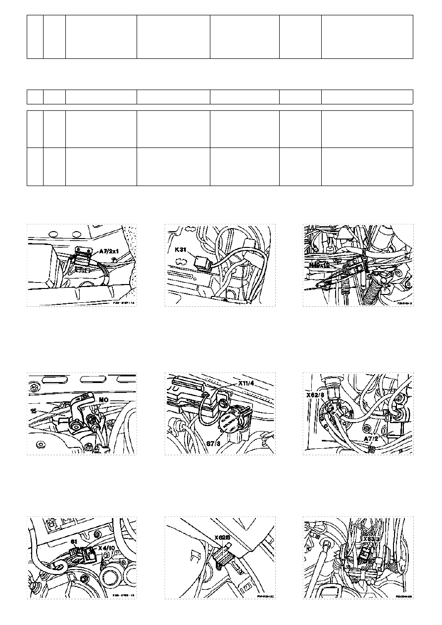
Figure 1
Figure 2
Figure 3
N49x1/2
Plug connection, steering angle sensor
A7/2x1
Plug connection, 4MATIC valve control module
K31
Normal operation/service relay
(near jacket tube)
(below the rear right seat bench)
(below the right footrest)
Test program - Electrics
Testing
Figure 4
Figure 5
Figure 6
X62/8 Plug connection, rear axle distributor
15
Service valve
S7/3
Normal operation/Service selection switch (4MATIC)
(as of 05/91)
Test program - Electrics
Testing
Strona 3/4
© Daimler AG, 01.12.10, G/03/09 / dh0801pf00023x / 8.1 - 4MATIC 23 - Test program - Electrics Testing Model 124.2/3
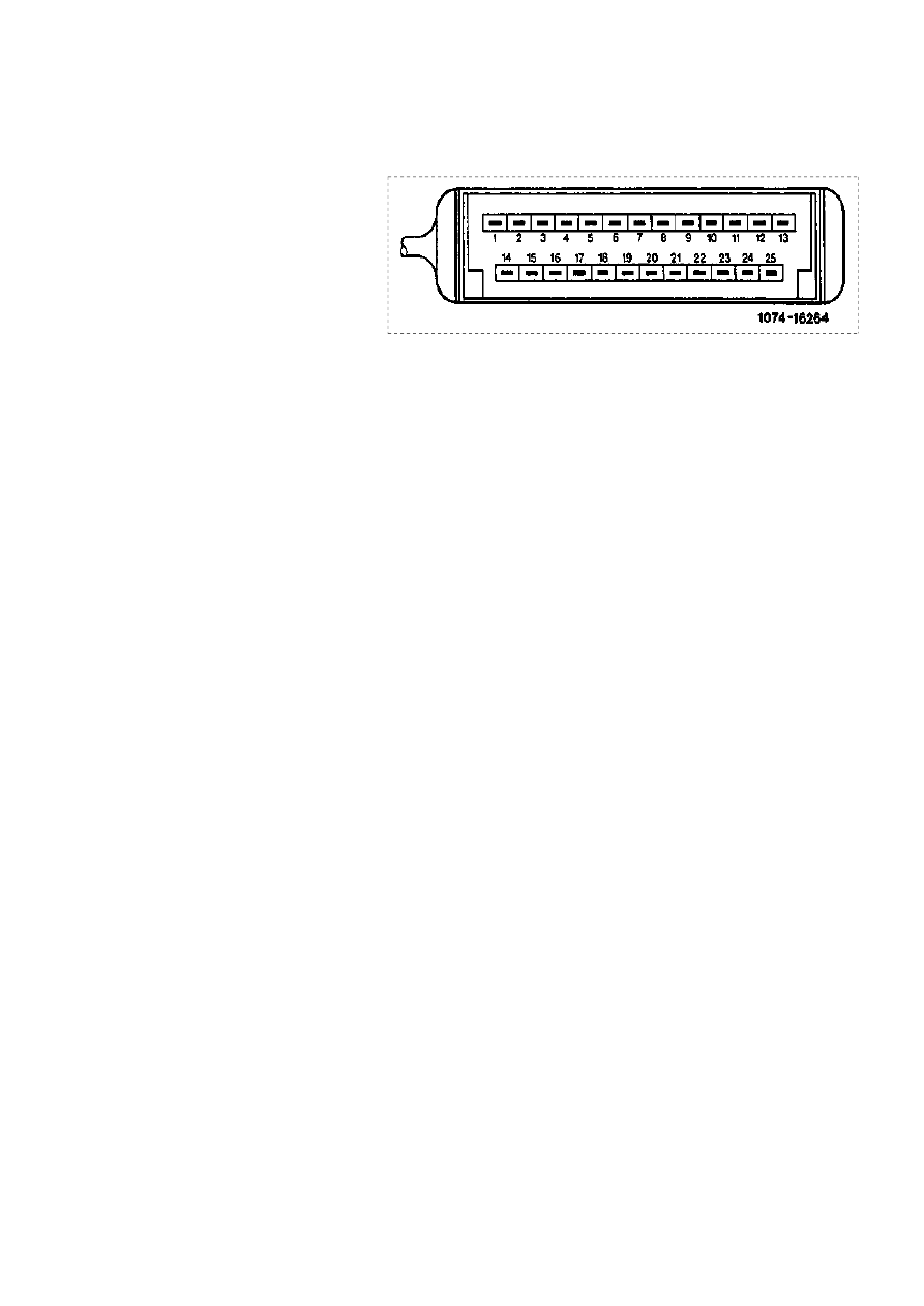
Figure 7
Figure 8
Figure 9
X83/3 Connector, instrument cluster (CLUS)/
X4/10 Connector, terminal 30/terminal 61
X62/8 Connector, rear axle distributor
4MATIC warning lamp (3-pin)
Battery (3-pin) (in right of the wheelhouse
(to the right of the front-wall pillar)
(below the fuse and relay boxes (F1))
in front of battery)
Test program - Electrics
Testing
Assignment on coupling for 4MATIC control module
(N30/3)
Figure 10
1
Voltage supply from overvoltage protection relay 87E/87L/30a, 9-pin
(terminal 87E)
2
Ground, battery (W10)
-
3
4
Front axle drive train valve A7/2y1
5
Front left speed sensor (L6/1) signal from ABS control module (N30)
6
Center differential lock valve A7/2y2
7
Steering angle sensor N49 (-)
8
Rear axle differential lock valve A7/2y3
9
ASD/4MATIC diagnostic output/warning lamp (A1e24)
10
Rear axle speed sensor (L6) signal from ABS control module (N30)
11
Voltage, terminal 61
-
12
13
Right front speed sensor (L6/2) signal from ABS control module (N30)
-
14-15
16
Stop lamp switch, (4-pin) (S9/1), normally open contact
17-18
Steering angle sensor (N49) signal
19
Voltage supply from overvoltage protection relay 87E/87L/30a, 9-pin
(terminal 30a)
20
Oil pressure switch (A7/2s1)
-
21-22
23
ABS signal
24
ASD/4MATIC function indicator lamp (A1e25)
Strona 4/4
© Daimler AG, 01.12.10, G/03/09 / dh0801pf00023x / 8.1 - 4MATIC 23 - Test program - Electrics Testing Model 124.2/3
Wyszukiwarka
Podobne podstrony:
Diagnostyka elektrofizjologiczna miasteni i zespołów miastenicznych
[4matic] funkcjonowanie elektroniki
DIAGNOSTYKA ELEKTROKARDIOLOGICZNA (EKG)
Diagnostyka elektr wspomagania ukł kierow
Diagnostyka lab wod elektrolit
Naprawa elektroniki w aucie, Diagnostyka dokumety
etzi-zagadnienia do zaliczenia-2016, ELEKTRONIKA I TELEKOMUNIKACJA PRZ - systemy pomiarowe i diagnos
Diagnostyka silnika-warsztat, ELEKTRONIKA
Diagnostyka zasilania energią elektryczną pojazdu samochodowego
w6 Woda i elektrolity, Diagnostyka laboratoryjna, Diagnostyka laboratoryjna
obsługa elektromechanicznego hamulca postojowego, auta, Diagnostyka dokumety, procedury diagnostyczn
diagnozowanie ukladu elektrycznego, UTP Bydgoszcz - Transport, V semestr, diagnostyka techniczna
7.Czy możliwa jest rejestracja czystych widm elektronowych, BIO, Diagnostyka Laboratoryjna, analiza
Kliniczne+znaczenie+diagnostyki+obrazowej, Prezentacje ELEKTRO
elektroforeza na diagnostykę
Montaż zimnej katody jako podświetlania zegarów w VW (na podstawie Golfa MK II), MOTORYZACJA, elektr
więcej podobnych podstron