
Virtual components in assemblies
Publication Number
spse01690


Virtual components in assemblies
Publication Number
spse01690

Proprietary and restricted rights notice
This software and related documentation are proprietary to Siemens Product
Lifecycle Management Software Inc.
© 2011 Siemens Product Lifecycle Management Software Inc. All Rights Reserved.
Siemens and the Siemens logo are registered trademarks of Siemens AG. Solid Edge
is a trademark or registered trademark of Siemens Product Lifecycle Management
Software Inc. or its subsidiaries in the United States and in other countries. All
other trademarks, registered trademarks or service marks belong to their respective
holders.
2
Virtual components in assemblies
spse01690

Contents
Creating and publishing Virtual Components . . . . . . . . . . . . . . . . . . . . 2-1
Activity: Virtual component editor . . . . . . . . . . . . . . . . . . . . . . . . . . . . . 3-1
Activity: Virtual component editor . . . . . . . . . . . . . . . . . . . . . . . . . . . . . A-1
Define the virtual assembly structure . . . . . . . . . . . . . . . . . . . . . . . . . . . . . . A-1
Assign geometry to parts . . . . . . . . . . . . . . . . . . . . . . . . . . . . . . . . . . . . . . . A-3
Create component sketches . . . . . . . . . . . . . . . . . . . . . . . . . . . . . . . . . . . . A-12
Position the component sketches in the existing parts as part of the virtual
component structure . . . . . . . . . . . . . . . . . . . . . . . . . . . . . . . . . . . . . . . . . A-19
Publish the virtual assembly . . . . . . . . . . . . . . . . . . . . . . . . . . . . . . . . . . . A-24
Create the frame from the sketch geometry . . . . . . . . . . . . . . . . . . . . . . . . . A-25
Model the front axle . . . . . . . . . . . . . . . . . . . . . . . . . . . . . . . . . . . . . . . . . A-29
Model the rear axle . . . . . . . . . . . . . . . . . . . . . . . . . . . . . . . . . . . . . . . . . . A-30
Model the wheel hub . . . . . . . . . . . . . . . . . . . . . . . . . . . . . . . . . . . . . . . . . A-31
Model the tire . . . . . . . . . . . . . . . . . . . . . . . . . . . . . . . . . . . . . . . . . . . . . . A-31
Model the sheet metal deck . . . . . . . . . . . . . . . . . . . . . . . . . . . . . . . . . . . . A-32
Mirror the wheels . . . . . . . . . . . . . . . . . . . . . . . . . . . . . . . . . . . . . . . . . . . A-32
Activity summary . . . . . . . . . . . . . . . . . . . . . . . . . . . . . . . . . . . . . . . . . . . A-33
spse01690
Virtual components in assemblies
3


Lesson
1
Introduction
Welcome to self paced training for Solid Edge. This course is designed to educate you
in the use of Solid Edge. The course is self-paced and contains instruction followed
by activities.
Solid Edge self-paced courses
•
spse01510—Sketching
•
spse01515—Constructing base features
•
spse01520—Moving and rotating faces
•
spse01525—Working with face relationships
•
spse01530—Constructing treatment features
•
spse01535—Constructing procedural features
•
spse01536—Modeling synchronous and ordered features
•
spse01540—Modeling assemblies
•
spse01545—Creating detailed drawings
•
spse01546—Sheet metal design
•
spse01550—Practicing your skills with projects
•
spse01560—Modeling a Part Using Surfaces
•
spse01610—Solid Edge frame design
•
spse01640—Assembly patterning
•
spse01645—Assembly systems libraries
•
spse01650—Working with large assemblies
•
spse01655—Revising assemblies
•
spse01660—Assembly reports
•
spse01665—Replacing parts in an assembly
•
spse01670—Designing in the context of an assembly
spse01690
Virtual components in assemblies
1-1

Lesson 1
Introduction
•
spse01675—Assembly features
•
spse01680—Inspecting assemblies
•
spse01685—Alternate assemblies
•
spse01686—Adjustable parts and assemblies
•
spse01690—Virtual components in assemblies
•
spse01691—Exploding assemblies
•
spse01692—Rendering assemblies
•
spse01693—Animating assemblies
•
spse01695—XpresRoute (tubing)
•
spse01696—Creating a Wire Harness with Harness Design
•
spse01424—Working with Solid Edge Embedded Client
Start with the tutorials
Self-paced training begins where tutorials end. Tutorials are the quickest way for
you to become familiar with the basics of using Solid Edge. If you do not have any
experience with Solid Edge, please start by working through the tutorials for basic
part modeling and editing before starting this self-paced training.
1-2
Virtual components in assemblies
spse01690
Lesson
2
Creating and publishing
Virtual Components
When you start a new design project, you may want to define the overall product
structure for the project before creating new Solid Edge documents, or before
positioning 3D geometry for existing Solid Edge documents in the top-level assembly.
In effect, you use a top-down design approach to define the assembly structure using
virtual components as place holders until real components are defined.
You can use the Virtual Component functionality in Solid Edge or in Teamcenter to
define the assembly structure for a new design project.
When you have finished defining the assembly structure, you can publish the
assembly. Publishing the assembly creates the new Solid Edge documents required,
copies assembly sketch geometry to the new documents, and adds the 3D geometry
for existing Solid Edge documents to the assembly.
Virtual components in Solid Edge
The basic workflow for creating and publishing a virtual assembly in the unmanaged
Solid Edge environment is:
•
Define the virtual components you need.
•
Add existing documents to the virtual assembly structure.
•
Assign 2D geometry to individual virtual components.
•
Position virtual components.
•
Publish virtual components.
spse01690
Virtual components in assemblies
2-1

Lesson 2
Creating and publishing Virtual Components
To make it easier to understand the concepts and capabilities of the virtual
component functionality in Solid Edge, a Virtual Component tutorial is available.
Virtual components in a Teamcenter-managed Solid Edge environment
While you can use the virtual component functionality in Solid Edge to develop
unmanaged assembly structures, most often in a managed environment, your
product structure is created and modified in another Teamcenter PDM client such
as Teamcenter Structure Manager. Then the empty items that are created in the
PDM client are opened for further development along with the remaining structure
in either Solid Edge or Structure Editor.
Note
As a best practice, you should choose between using Solid Edge Virtual
Components and a workflow where Teamcenter empty items are created in a
PDM client. Using both in the same structure is not recommended.
Once you have finished defining the assembly structure, you can publish the virtual
components, converting non-modeled objects into physical documents containing
Solid Edge 3D datasets. Publishing the components assigns the Solid Edge template
(part, assembly, sheet metal or weldment), and Teamcenter attributes to the real
document.
The basic workflow for working with Teamcenter-managed virtual assembly is:
•
Create the virtual components you need using a Teamcenter PDM client.
•
Open the structure in Solid Edge where you can view the structure in PathFinder.
•
Add existing documents to the virtual assembly structure.
Note
If you are working in Solid Edge in the Teamcenter mode, you cannot
place unmanaged parts into a Teamcenter-managed virtual component
structure.
•
Publish virtual components.
•
Upload the real document into the Teamcenter database.
Defining the assembly structure
The Virtual Component Structure Editor command defines the assembly structure
for a new design project in an unmanaged environment. When you click the Virtual
Component Structure Editor command, the Virtual Component Structure Editor
dialog box is displayed.
The Virtual Component Structure Editor defines the name and document type for
new virtual components, and allows you to drag any existing Solid Edge documents
into the virtual assembly structure.
Defining new virtual components
You use the right pane on the Virtual Component Structure Editor to define
virtual components and organize the assembly structure. The Component Type
2-2
Virtual components in assemblies
spse01690

Creating and publishing Virtual Components
options on the right pane of the Virtual Component Structure Editor define the
document type for new virtual components:
•
Assembly components
•
Part components
•
Sheet metal components
The Name option assigns a name to the virtual component you are creating.
You can select a default name from the list, or type the name you want in the
Name box.
You can customize the Names list by editing VCNames.txt in the Solid Edge
Program folder. Separate sections in VCNames.txt define unique virtual
component names for part, sheet metal, and assembly components.
After you define the component type and name, you can click the Add Virtual
Component button on the Virtual Component Structure Editor dialog box to
add the virtual component to the tree structure list. You can also add a virtual
component to the tree structure list by pressing Enter after typing the virtual
component name.
Note
When you create a virtual component, it has no physical position and no
associated graphics. Later, you can position the virtual component and/or
assign graphics to it.
You can use the Promote Component and Demote Component buttons to further
define the assembly structure. For example, if you want to move a component
from a virtual subassembly into the next higher level assembly, you can select
the component and click the Promote Component button.
You can also drag virtual components within the Virtual Component Structure
Editor dialog box to rearrange the assembly structure. For example, you can
drag a virtual part from one virtual subassembly to another virtual subassembly.
spse01690
Virtual components in assemblies
2-3
Lesson 2
Creating and publishing Virtual Components
Adding existing documents to the virtual structure
You can also place existing Solid Edge documents into the assembly structure
using the Virtual Component Structure Editor dialog box.
The left pane on the Virtual Component Structure Editor dialog box browses
to and selects existing documents on your computer or another computer on
your network. If you are working in Teamcenter mode, you can select existing
documents from your Teamcenter database.
You can place an existing document into the virtual assembly structure in one of
two ways: as a pre-defined component or as a real component.
Pre-defined components
Pre-defined components are virtual components that are based on an existing
document. You cannot place 3D geometry using a pre-defined component, but
you can create 2D geometry in the parent document (A), then position the 2D
geometry in the assembly sketch (B). You can reuse existing documents in
new design projects without the overhead of 3D geometry.
When you clear the Add As Real Component option on the Virtual Component
Structure Editor, then drag an existing component into the right pane of the
structure editor, the component is placed as a pre-defined component. If you
want to add the document to a virtual subassembly, position the cursor over
the virtual subassembly when dropping the pre-defined component.
Pre-defined components are typically purchased or released parts that are
not subject to significant changes.
Adding real components
When you set the Add As Real Component option on the Virtual Component
Structure Editor before you drag an existing document into the virtual
assembly structure, the 3D geometry associated with the component is added
to the assembly. When this option is set you can only place the component in
the top-level assembly.
The component is placed in the assembly hidden, with no relationships
applied, and is oriented in the assembly by aligning the base reference
planes of the component with the base reference planes in the assembly.
You can position the real component within the assembly sketch using
assembly relationships such as mate and align, or 2D relationships and
dimensions such as Connect and Distance Between.
2-4
Virtual components in assemblies
spse01690

Creating and publishing Virtual Components
Copying virtual and pre-defined components
You can specify that the same part or subassembly occurs more than once
using the Virtual Component Structure Editor dialog box. To specify that a
component occurs more than once, you can select an existing virtual component
or pre-defined component, then click the Copy Definition command on the
shortcut menu.
This copies the component name and component type to the Name box and
Component Type list. You can then press Enter or click Add Virtual Component
to add the component to the tree structure list. You can also add the same
component multiple times by pressing Enter repeatedly.
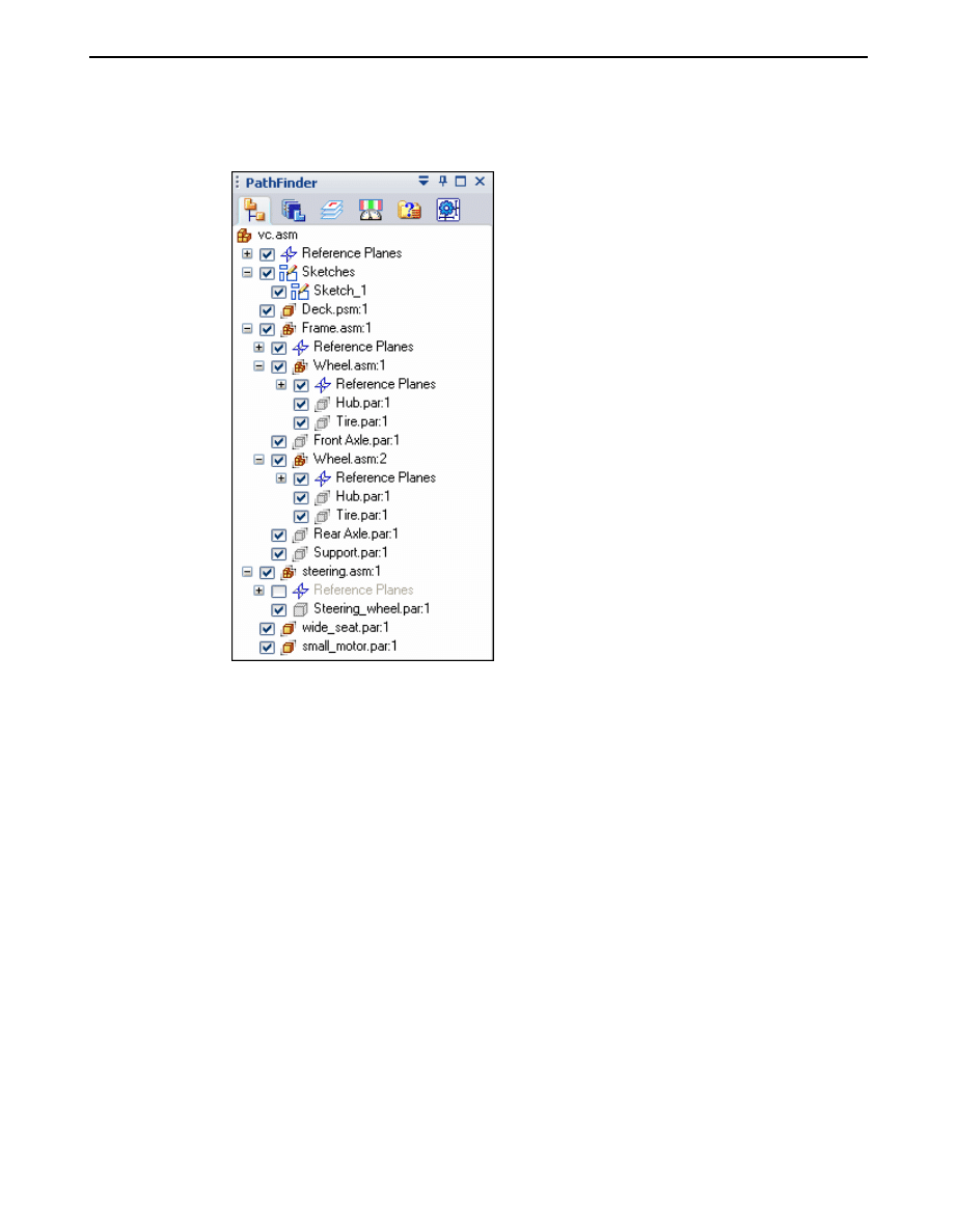
Saving the tree structure
When you click the OK button on the Virtual Component Structure Editor dialog
box, the virtual assembly structure you defined is added to the PathFinder tab.
You can make changes to the virtual assembly structure later using the Virtual
Component Structure Editor dialog box.
You can dismiss the Virtual Component Structure Editor dialog box without
saving changes by clicking the Cancel button.
Assigning sketch geometry to Virtual Components
You can assign 2D sketch geometry from the assembly layout to a virtual component.
You can create the 2D geometry before or after you define the assembly structure.
Assigning geometry to a virtual component defines its size and position in the
assembly sketch. You can only assign geometry to one occurrence of a particular
virtual component.
When you assign 2D geometry to a virtual component, it becomes the master, or
source component. You can edit the sketch geometry associated with the source
component directly. If there are additional occurrences of a particular virtual
component, they become slave or instance components.
The sketch geometry for an instance component is an associative copy of the
sketch geometry of the source component. When you update the sketch geometry
for a source component, the sketch geometry for the instance components updates
automatically. You cannot modify the sketch graphics for an instance component
directly.
You assign geometry to a virtual component using the Edit Definition command on
the Assembly PathFinder shortcut menu. This command is available only when an
assembly sketch window is open.
When you click the Edit Definition command, a command bar is displayed so you
can select the geometry and define an origin. You can select the 2D sketch geometry
using the cursor or by dragging a fence. When you finish selecting geometry, click
Accept or right-click to proceed to the Orientation Step.
spse01690
Virtual components in assemblies
2-5
Lesson 2
Creating and publishing Virtual Components
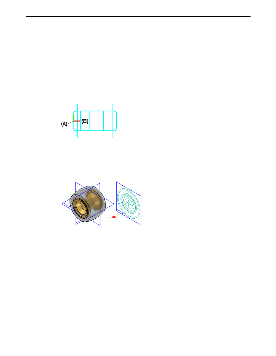
The Orientation Step defines the origin location for the virtual component and the
reference plane that the 2D sketch graphics are placed on when you publish the
virtual component. You can specify that the graphics are placed on one of the three
base reference planes.
When defining the origin you can specify that the origin is based on a keypoint or a
free space point. With either method you must also define the x-axis direction. When
you click the Finish button, a symbol is displayed that represents the origin (A) and
x-axis direction (B) for the virtual component geometry.
You can constrain to the origin point on a virtual component to position it within
the assembly.
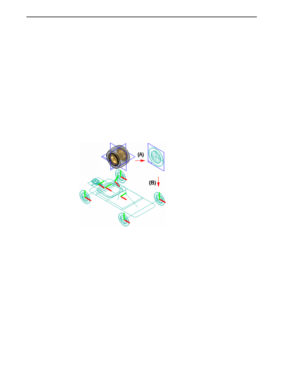
Creating sketch geometry for pre-defined Virtual Components
You create the sketch geometry for a pre-defined virtual component by opening
the parent document, then using the Component Sketch command to create a
component sketch.
There are two types of graphics you can create in a component sketch: component
image graphics, and wireframe graphics. Component image graphics are created
using the Component Image command. This command creates a 2D representation
of the visible edges on a part.
Component image graphics are not individually selectable in the assembly sketch,
but provide a reference envelope.
You supplement the component image graphics with wireframe graphics you
create using the Include command or drawing wireframe graphics manually. The
wireframe graphics can be selected and used for constraining the component sketch
in the assembly sketch.
You typically would create both types of graphics for a component sketch. In
some cases, you may only create component image graphics, then use the virtual
component symbol origin to constrain the pre-defined component in the assembly
sketch.
Using too many wireframe graphic elements can impact performance when placing
the component sketch in the assembly sketch.
2-6
Virtual components in assemblies
spse01690

Creating and publishing Virtual Components
Updating sketch geometry for pre-defined Virtual Components
As discussed earlier, pre-defined components are typically purchased or released
parts. If the parent 3D geometry for a pre-defined component sketch changes, you
must delete the component image graphics and create new graphics using the
Component Image command.
You can then open the assembly sketch and select the pre-defined component within
PathFinder. Click the Update Component command on the shortcut menu to update
the pre-defined component graphics in the assembly.
Replacing pre-defined components
You can use the Replace command on the shortcut menu when a sketch is active to
replace a pre-defined component with another Solid Edge document you specify. you
can select the pre-defined component in Assembly PathFinder or the sketch window.
Displaying Virtual Component sketch geometry
Before you assign assembly sketch graphics to a virtual component, you use the
Show and Hide commands on the Layers tab shortcut menu to display and hide the
assembly sketch graphics. An effective layer management scheme can make working
with complex assembly sketches more productive.
After you assign assembly sketch graphics to a virtual component, you can use the
Show and Hide commands on the PathFinder shortcut menu to display and hide
the virtual component sketch graphics. For example, you can select the virtual
component in PathFinder, or in the graphics widow, then click the Show and Hide
commands on the shortcut menu.
You control the display of dimensions you apply to the sketch geometry by showing
and hiding the layers on which the dimensions were created, both before and after
you assign graphics to a virtual component.
Because geometric relationship handles do not reside on a layer, you always control
their display using the Relationship Handles command on the Tools menu when
in the assembly sketch.
Positioning Virtual Components
You use the Position Virtual Component command on the PathFinder shortcut menu
to position virtual components. This command is only available when you are
editing an assembly sketch. You can position an empty virtual component (a virtual
component that has no geometry assigned), an instance virtual component, or a
pre-defined component.
You can position a virtual component by dragging it from the PathFinder tab and
dropping it into the sketch window.
As discussed earlier, source virtual components are positioned as part of the process
of assigning geometry.
Positioning empty Virtual Components
If you have not assigned geometry to any occurrences of a particular virtual
component, you can select the virtual component in PathFinder, then click
the Position Virtual Component command on the shortcut menu. The virtual
spse01690
Virtual components in assemblies
2-7
Lesson 2
Creating and publishing Virtual Components
component symbol is attached to the cursor so you can position the virtual
component on the assembly sketch.
The symbol represents the approximate position for the empty virtual component
in the assembly. Later, you can select the empty virtual component entry
in PathFinder and use the Edit Definition command to assign geometry to
one occurrence of the empty virtual component. This instance of the virtual
component becomes the source virtual component.
The other occurrences of the virtual component update with the graphics you
assigned to the source component, and they become instance components.
You can then add relationships and dimensions to the sketch geometry to
precisely locate the virtual component in the assembly sketch.
Positioning instance Virtual Components
After you assign sketch geometry to a virtual component, it becomes the source
component for additional occurrences of that virtual component. You can select
another occurrence of the virtual component in PathFinder and use the Position
Virtual Component command on the shortcut menu to position the virtual
component on the active assembly sketch.
A copy of the sketch graphics that were assigned to the source component is
attached to the cursor. As discussed earlier, the sketch geometry for an instance
component is an associative copy of the sketch geometry of the source component.
You can apply relationships and dimensions to the sketch graphics or to the
virtual component symbol to precisely position the instance component on the
assembly sketch.
2-8
Virtual components in assemblies
spse01690
Creating and publishing Virtual Components
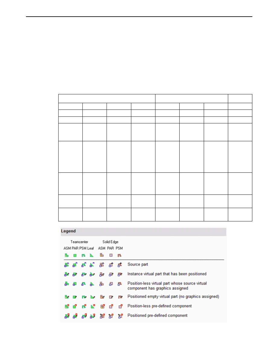
Determining the status of a Virtual Component
The symbols in PathFinder and the Virtual Component Structure Editor dialog box
reflect the current status of the virtual components in the assembly.
Teamcenter-managed non-modeled nodes can either be assembly or leaf nodes.
Assembly nodes contain references or children, while leaf nodes do not contain
references or children. The symbols in PathFinder, Assembly Reports, and the
Property Manager dialog box reflect the state of the virtual components in the
assembly. The following table explains the symbols used:
Teamcenter
Solid Edge
ASM
PAR
PSM
Leaf
ASM
PAR
PSM
Source part
Instance
virtual part
that has been
positioned
Position-less
virtual part
whose source
virtual
component
has graphics
assigned
Positioned
Empty
virtual part
(no graphics
assigned)
Position-less
pre-defined
component
Positioned
pre-defined
component
Note
The Teamcenter Status and Checked Out By information displayed in
PathFinder is not available for an object until it is published.
spse01690
Virtual components in assemblies
2-9

Lesson 2
Creating and publishing Virtual Components
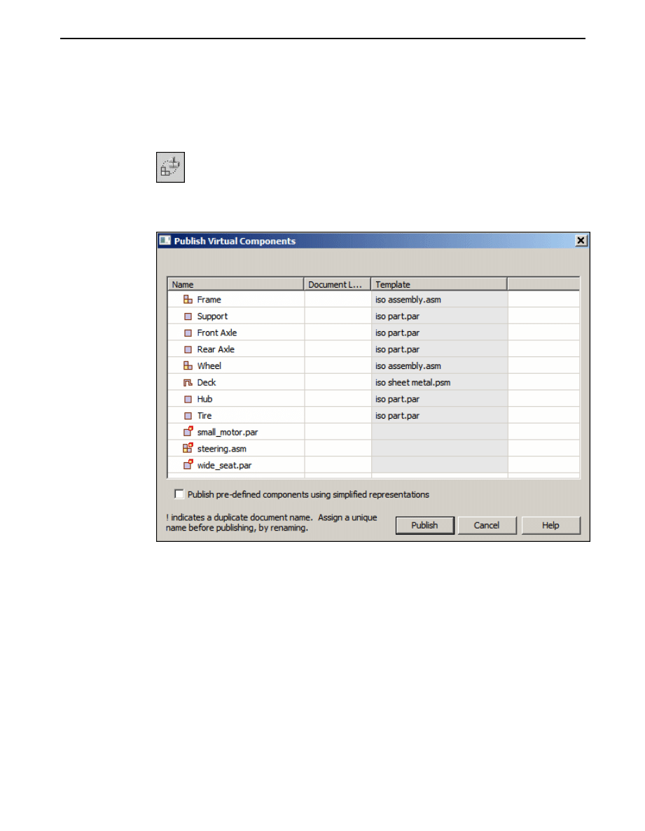
Publishing Virtual Components
When you are ready to create the document set for the new design project, you
can click the Publish Virtual Components command. You can then use the Publish
Virtual Components dialog box to specify the target folder and template you want to
use to create the document set.
In an unmanaged Solid Edge environment, when you click Publish, all virtual
components are published at one time. The unmanaged Solid Edge documents are
created using the names, folder path, and templates you specified.
If you have associated 2D assembly sketch graphics with source virtual components,
the sketch graphics, including dimensions and relationships, are copied to the proper
document as sketches. The sketch graphics are positioned in the new document
using the Publish On option you specified on the Edit Definition command bar when
you assigned the sketch geometry to the source component.
There is no associative link between the sketch graphics in the original assembly
and the sketch graphics copied to the new documents.
The sketch graphics associated with instance virtual components are deleted from
the source assembly.
You cannot publish a virtual component to the same folder as a real component of the
same name. For example, if you add both a pre-defined component named bolt.par
and a virtual component named bolt to the virtual component structure, they are not
allowed to reside in the same folder when you publish the virtual components.
Conflicts such as these are indicated in the Publish Virtual Components dialog box
using red text and an exclamation mark (!). In this example, you can resolve the
conflict by renaming the virtual component or by specifying a different folder for
the virtual component.
If you do not rename the virtual component or specify a different folder, the existing
document will be used and the new document for the virtual component will not be
created. The existing part is positioned as defined by the virtual component sketch,
but the sketch geometry is not added to the existing document.
Publishing pre-defined components using the simplified representation
If a simplified representation of a part or subassembly exists, you can specify that
the simplified representation is used for pre-defined components. When you set
the Publish Pre-defined Components Using Simplified Representations option on
the Publish Virtual Components dialog box, the simplified representation is used.
This can improve processing time and reduce document size. When you publish
a simplified representation of a subassembly, the subassembly is published as a
single unit and the assembly structure is not loaded into memory. The assembly
structure is also not displayed within PathFinder.
You can use commands on the PathFinder shortcut menu to specify whether the
simplified or as designed version of the parts and subassemblies are displayed.
For more information on working with simplified parts and assemblies, see the
Simplifying Parts and Simplifying Assemblies Help topics.
Publishing documents in the Teamcenter-managed environment
When you are ready to create the document set for the new design project, you have
three options. You can perform an ad hoc publish on a single object by selecting
2-10
Virtual components in assemblies
spse01690

Creating and publishing Virtual Components
the virtual component in PathFinder and dragging it into the Solid Edge graphic
window. You are then prompted to choose the template for the object to give it a
Solid Edge dataset, and then the New Document dialog box displays so you can
check in the real document.
Another option is to use the Publish Virtual Components command. You can then
use the Publish Virtual Components dialog box to select components for either a
partial or full publish, and to determine the template you want to use to create
the document.
During a partial publish, you select a component of an assembly for publishing by
selecting the associated check box. Then you are given the opportunity to assign a
template. The New Document common property dialog box assigns Teamcenter
attributes, and the physical document is created with a Solid Edge dataset.
A full publish involves selecting all components of a structure. The entire virtual
structure is published at the same time. You use the New Document common
property dialog box to assign Teamcenter attributes, and the documents are created
with Solid Edge datasets.
In all three cases, if a virtual component is denoted as an assembly, only Solid
Edge assembly templates are displayed during template selection. If the virtual
component is a leaf node (one that has no references or children), then you can
choose from the 3D Solid Edge templates during template selection.
Virtual Components and assembly reports
If the assembly for which you are creating a report contains virtual components, you
should always use the Reports command in the Assembly environment.
When you run the Reports command from Windows Explorer on an assembly that
has virtual components, the virtual components will not be contained in the report.
If the assembly contains only virtual components, a message may be displayed that
states that no parts are in the file.
When you run the Reports command from Windows Explorer on an assembly that
has virtual components, the Assembly Report shows Teamcenter virtual components
and uses the same symbols for identification that you see in PathFinder.
Assigning properties to Virtual Components
When an active document contains a virtual component, you can use the Property
Manager command to modify existing properties or create new properties for the
virtual component in Solid Edge.
Note
Virtual components created in Teamcenter are shown, but are read-only and
cannot be edited.
When you select the Property Manager command, the Property Manager dialog
box is displayed for editing property values. Any properties that you cannot edit
are disabled and appear in gray.
To edit a value, click the appropriate property cell and type in the new value. When
you edit a property, if the document containing the property is a managed document,
it is checked out to prevent others from making changes. After you edit a property
value, the property cell is underlined to indicate that it has been changed. The cell
spse01690
Virtual components in assemblies
2-11

Lesson 2
Creating and publishing Virtual Components
remains underlined until you click the Save button to save the changes or click the
Restore button to set the value back to the previous value. You can use the Copy,
Cut, and Paste buttons to edit information between cells. When you click OK, the
property changes are written back to the document in memory. The changes are not
written until you save the document.
When you publish the virtual components, the properties you assigned to the virtual
components are added to the new documents.
For more information on editing document properties, see Document Properties.
2-12
Virtual components in assemblies
spse01690

Lesson
3
Activity: Virtual component
editor
Activity guides you through the process of laying out an assembly using the virtual
component structure editor and then publishing the assembly to create the basic
design which is further refined.
Turn to Appendix A for the activity.
spse01690
Virtual components in assemblies
3-1


Lesson
4
Lesson review
Answer the following questions:
1.
How is assembly sketch geometry assigned to a virtual component?
2.
What is the purpose of a component sketch?
3.
What is created when virtual components are published?
spse01690
Virtual components in assemblies
4-1


Answers
1.
How is assembly sketch geometry assigned to a virtual component?
The geometry can be assigned by editing the profile of a sketch, and right clicking
a virtual component and editing the definition. Geometry from the sketch is
assigned and oriented in the position it will be when the component is published.
2.
What is the purpose of a component sketch?
A component sketch creates sketch geometry in an existing part or assembly
needed to position the component in a virtual assembly such that when the
virtual assembly is published, the part will be in the correct position relative to
the other components in the assembly.
3.
What is created when virtual components are published?
Part, sheet metal and assembly files are created from designated templates and
if sketch geometry has been assigned to these components, sketches will exist in
the newly created documents. The pathfinder structure is the same as it was in
the component editor. Existing parts that have been positioned with component
sketches are placed in the assembly.
spse01690
Virtual components in assemblies
0-1


Lesson
5
Lesson summary
In this lesson you learned how to create a virtual assembly structure using virtual
components. Sketch geometry in the assembly file was assigned to virtual part
files and once published, the sketch geometry was moved into those files and used
to create parts. Existing parts were placed in the virtual structure and positioned
using component sketches. This is a top down approach to laying out and modeling
complex assemblies.
spse01690
Virtual components in assemblies
5-1

A
Activity: Virtual component
editor
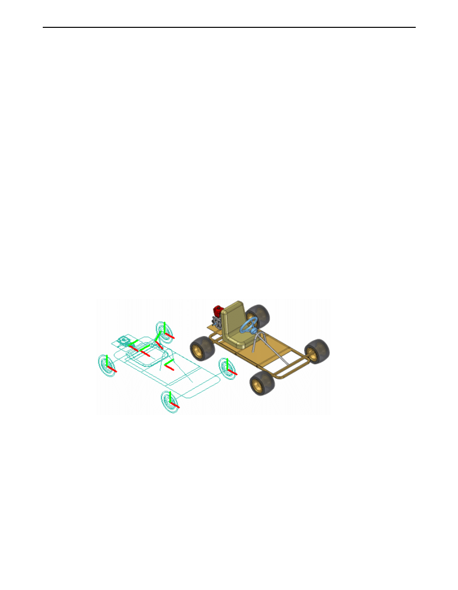
Overview
This activity shows top down assembly design using the virtual component structure
editor.
Objectives
The virtual component editor allows a designer to use Solid Edge assembly sketches
as a component layout for a new assembly. The orientation and positioning of future
parts and subassemblies can be defined in the new assembly as well as existing parts
and subassemblies. In this activity, you will use a Solid Edge assembly sketch to
define geometric positions of parts that will be created in a top down method. When
the virtual components are published, the files needed to complete the assembly will
exist and the sketches will be used to create the new geometry.
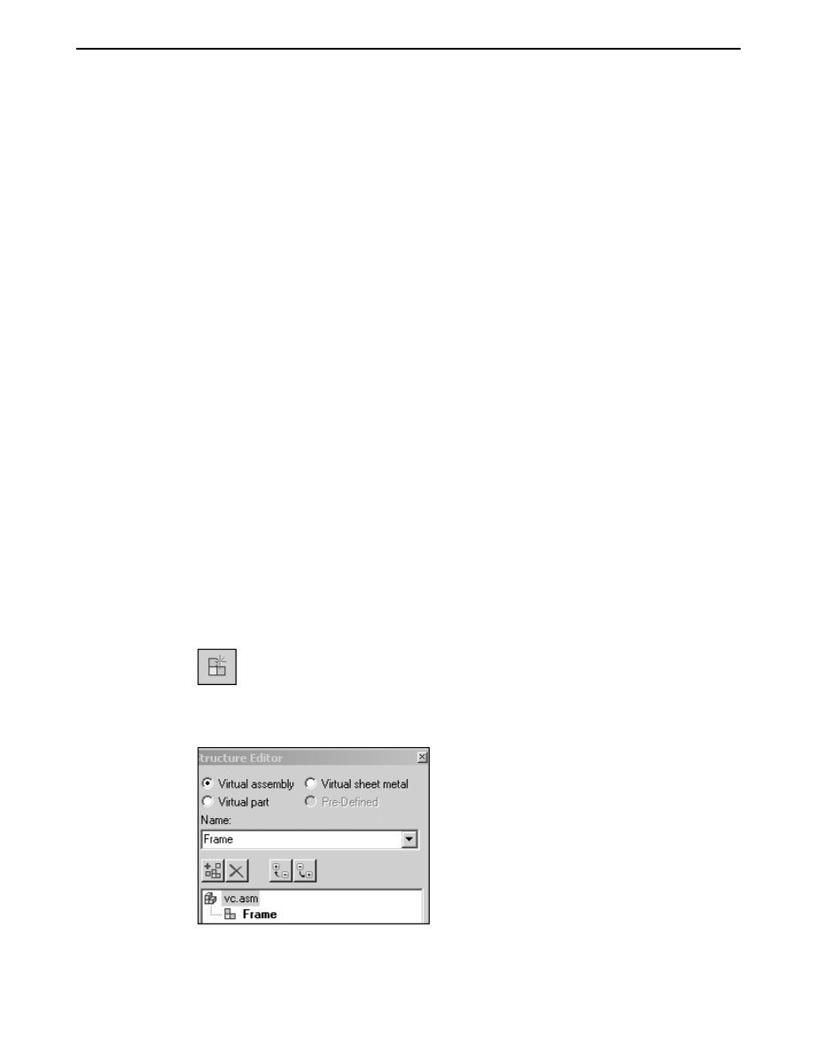
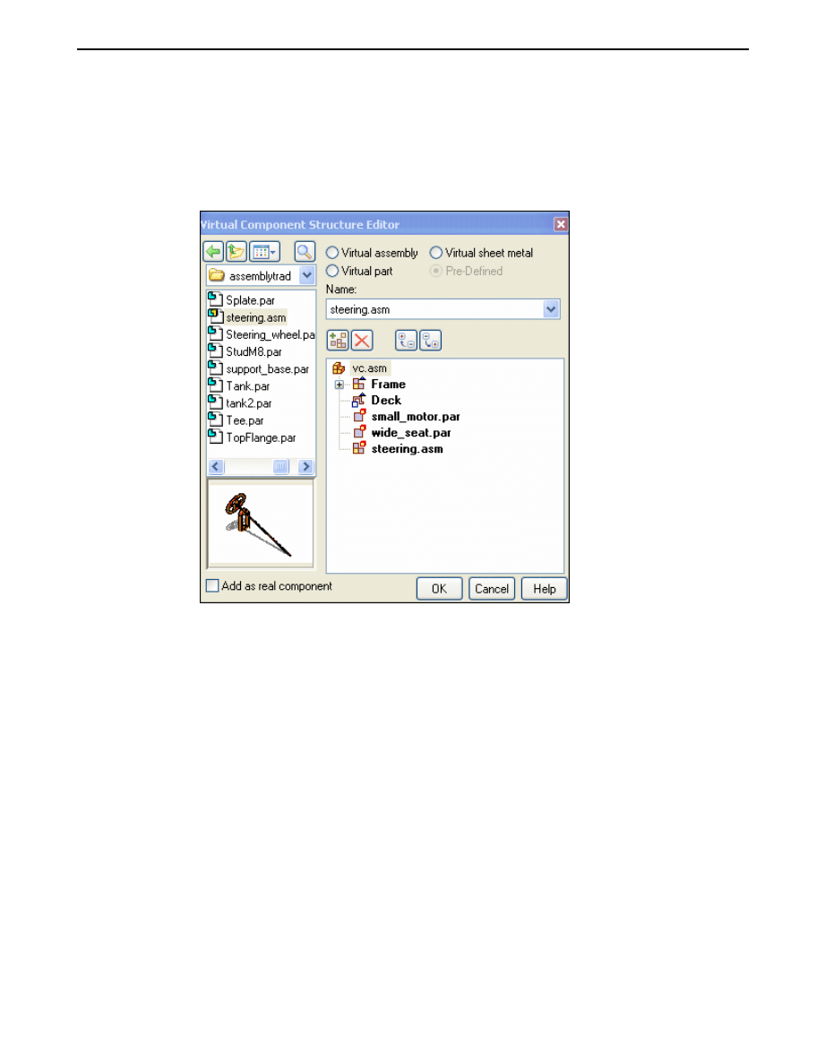
Define the virtual assembly structure
▸
Open vc.asm located in the folder where you put the activity documents.
▸
Click the Home tab, in the Assemble group, click Component Structure Editor.
▸
Click the Virtual assembly option to set the type. Type Frame in the Name
box and press the Enter key.
spse01690
Virtual components in assemblies
A-1
A
Activity: Virtual component editor
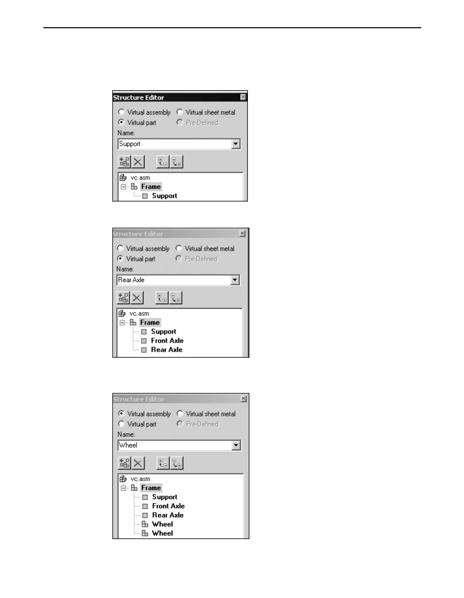
▸
Click the Frame assembly, and then click the Virtual part option. Enter Support
in the Name box.
▸
Click the Frame assembly, and add the virtual parts Front Axle and Rear Axle.
▸
Click the Virtual assembly button and enter Wheel in the Name box. Enter
Wheel again to create a second assembly of the same name.
A-2
Virtual components in assemblies
spse01690
Activity: Virtual component editor
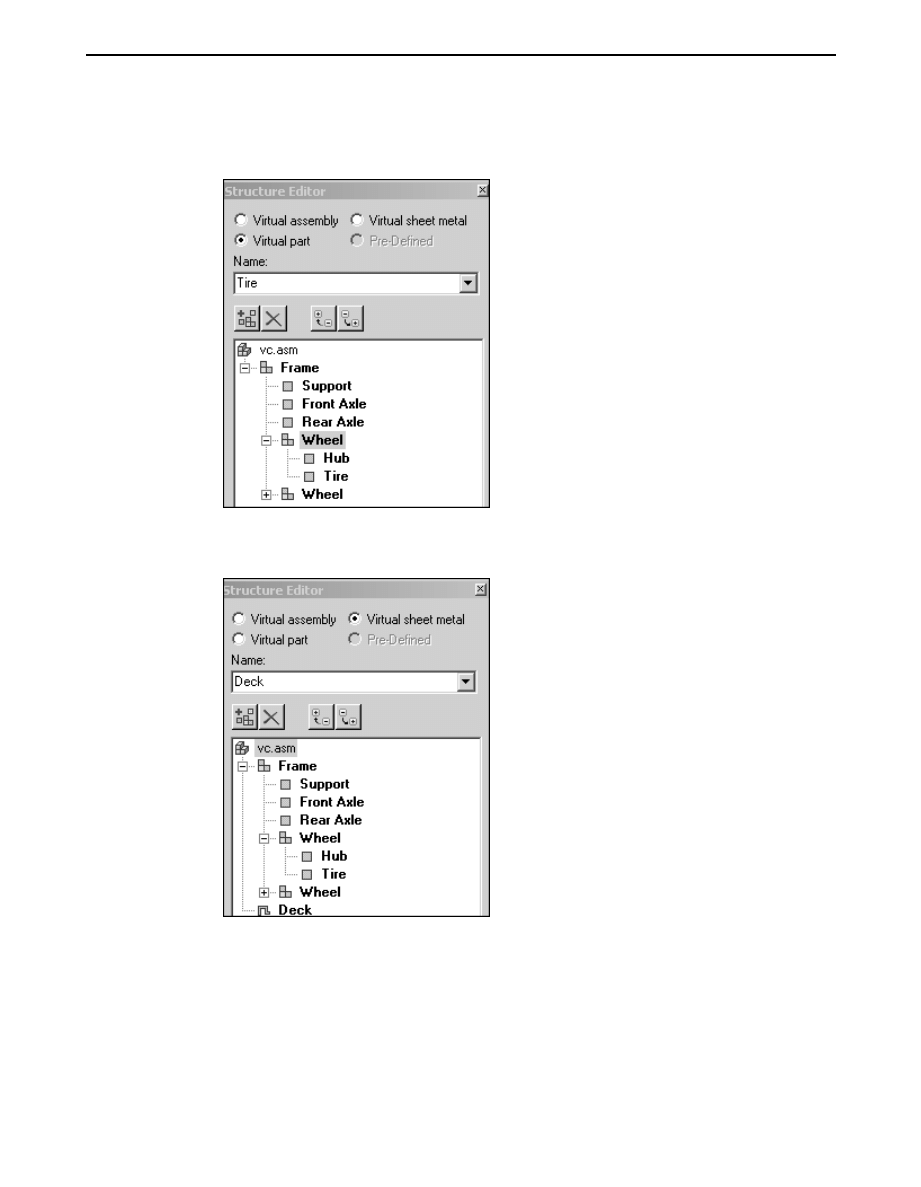
▸
Select the Wheel assembly and click the Virtual part option. Enter Hub, and
then enter Tire in the Name box.
▸
Select vc.asm. Click the Virtual sheet metal option and add the sheet metal part
Deck, then click OK to exit the Virtual Component Structure Editor.
Assign geometry to parts
Assign geometry from an existing sketch in vc.asm to parts in the virtual component
structure.
spse01690
Virtual components in assemblies
A-3
A
Activity: Virtual component editor
Note
Layers are used on the sketch so that geometry can easily be chosen and
assigned to the proper virtual component. Once assigned, a graphic sketch
element cannot be selected, preventing geometry being assigned to multiple
virtual components.
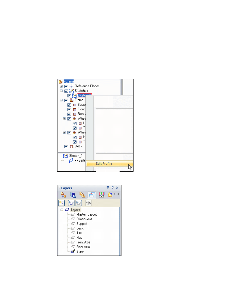
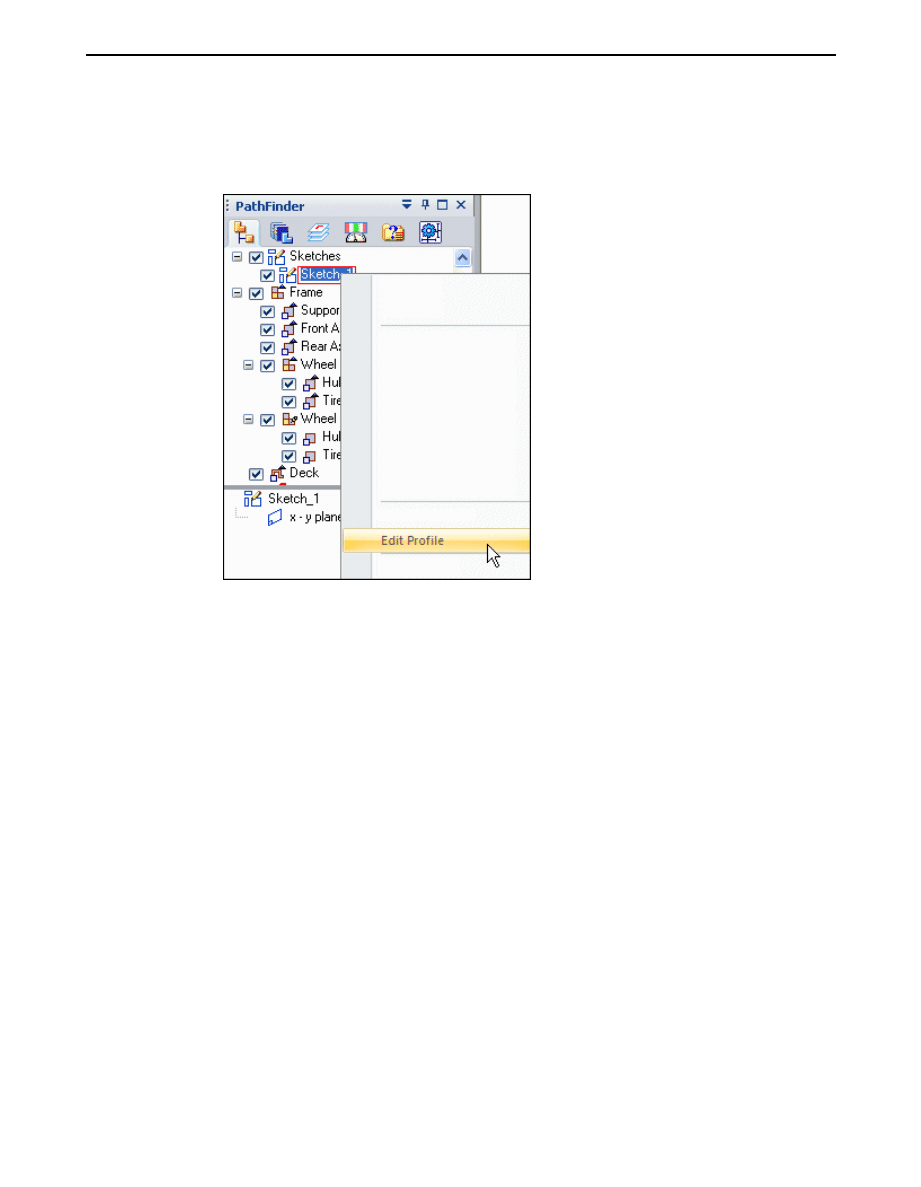
▸
On the Assembly PathFinder, expand the assembly structure as shown by
clicking the + symbol. Right-click Sketch_1 and select Edit Profile.
▸
Click the Layers tab on PathFinder.
A-4
Virtual components in assemblies
spse01690
Activity: Virtual component editor
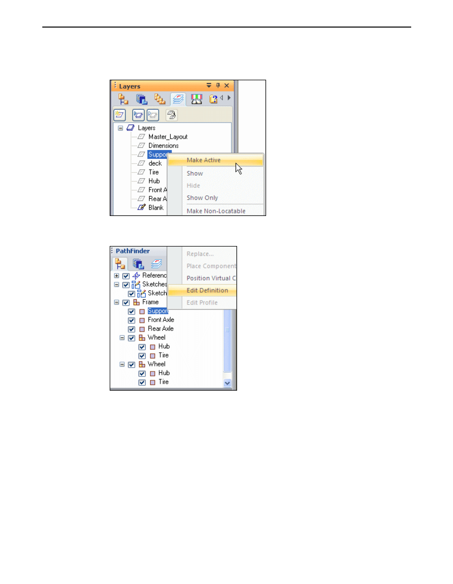
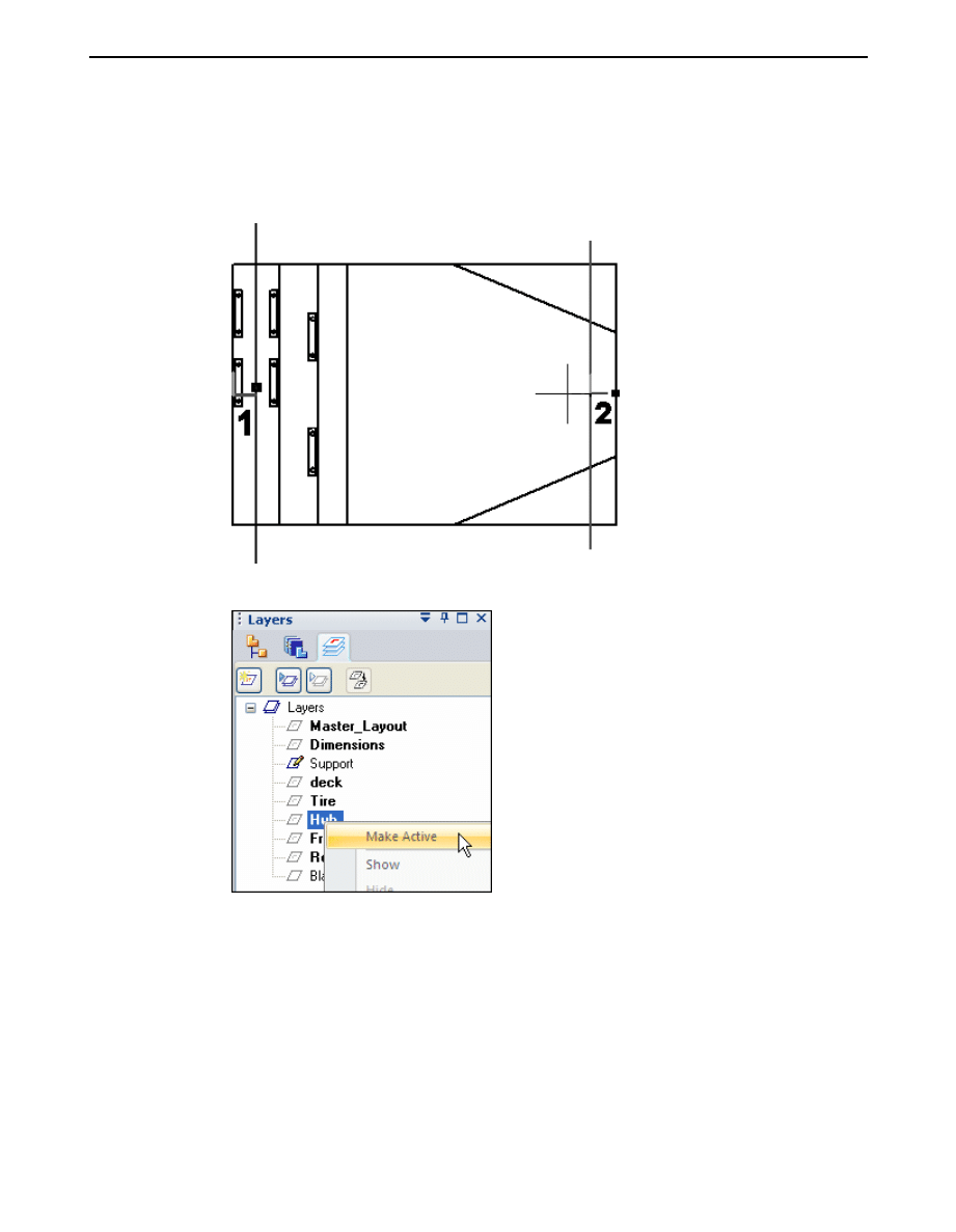
▸
Right-click the Support layer and click Make Active.
▸
On the Assembly PathFinder, right-click the virtual part Support and click Edit
Definition.
spse01690
Virtual components in assemblies
A-5
A
Activity: Virtual component editor
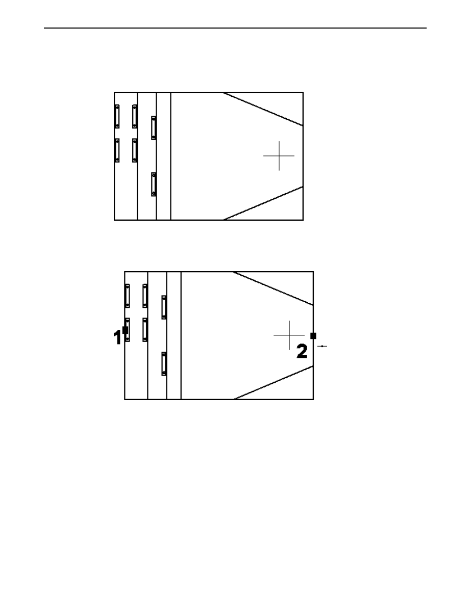
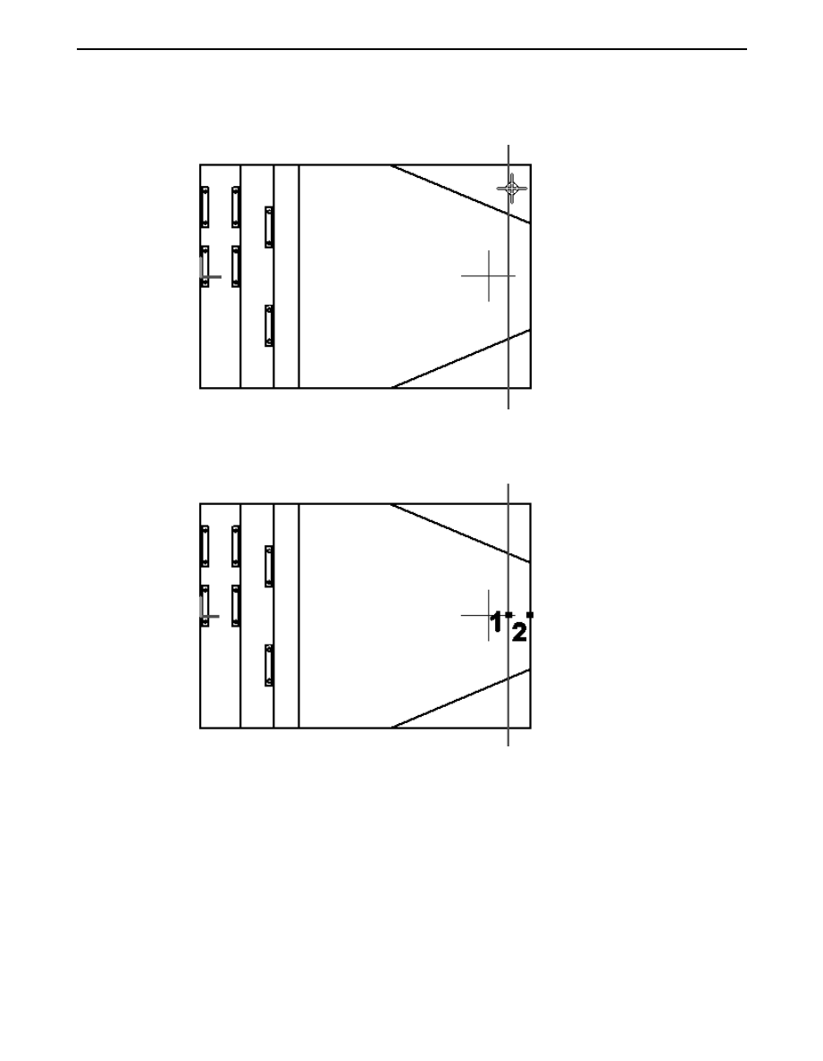
▸
Using the left mouse button, drag a box around the sketch to select everything
on the layer. Click the Accept button.
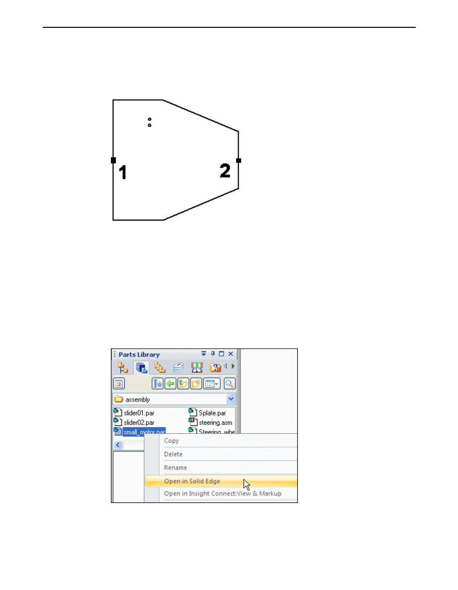
▸
After clicking Accept in the previous step, the origin of the orientation axis is
ready to be defined. To select the origin of the axis, click the midpoint of the left
most vertical line (point 1) as shown. To orient the x axis, click the midpoint of
the right most vertical line (point 2) as shown.
▸
Click Finish.
A-6
Virtual components in assemblies
spse01690
Activity: Virtual component editor
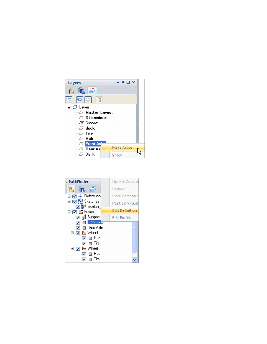
▸
In PathFinder select the Layers tab and right-click the layer Front Axle and
make it active as shown.
Note
Displayed geometry that has been assigned to a virtual component is not
selectable when editing the definition of another virtual component.
▸
On the Assembly PathFinder, right-click the virtual component, Front Axle, and
click Edit Definition.
spse01690
Virtual components in assemblies
A-7
A
Activity: Virtual component editor
▸
Select the Front axle as shown and click Accept.
▸
Position the front axle by selecting the origin point of the axis to be the midpoint
of the line as shown (point 1) and to orient the axis, select the midpoint of the
right-most vertical line as shown (point 2), then click Finish.
A-8
Virtual components in assemblies
spse01690
Activity: Virtual component editor
▸
In PathFinder, click the Layers tab and make Rear Axle the active layer. Click
the Assembly PathFinder tab, then right-click the virtual component Rear Axle
and then choose Edit Definition. Select the rear axle and accept. Orient the axis
using the midpoints of the lines shown below, and click Finish.
▸
Click the Layers tab. Right-click the layer Hub and make it active.
spse01690
Virtual components in assemblies
A-9
A
Activity: Virtual component editor
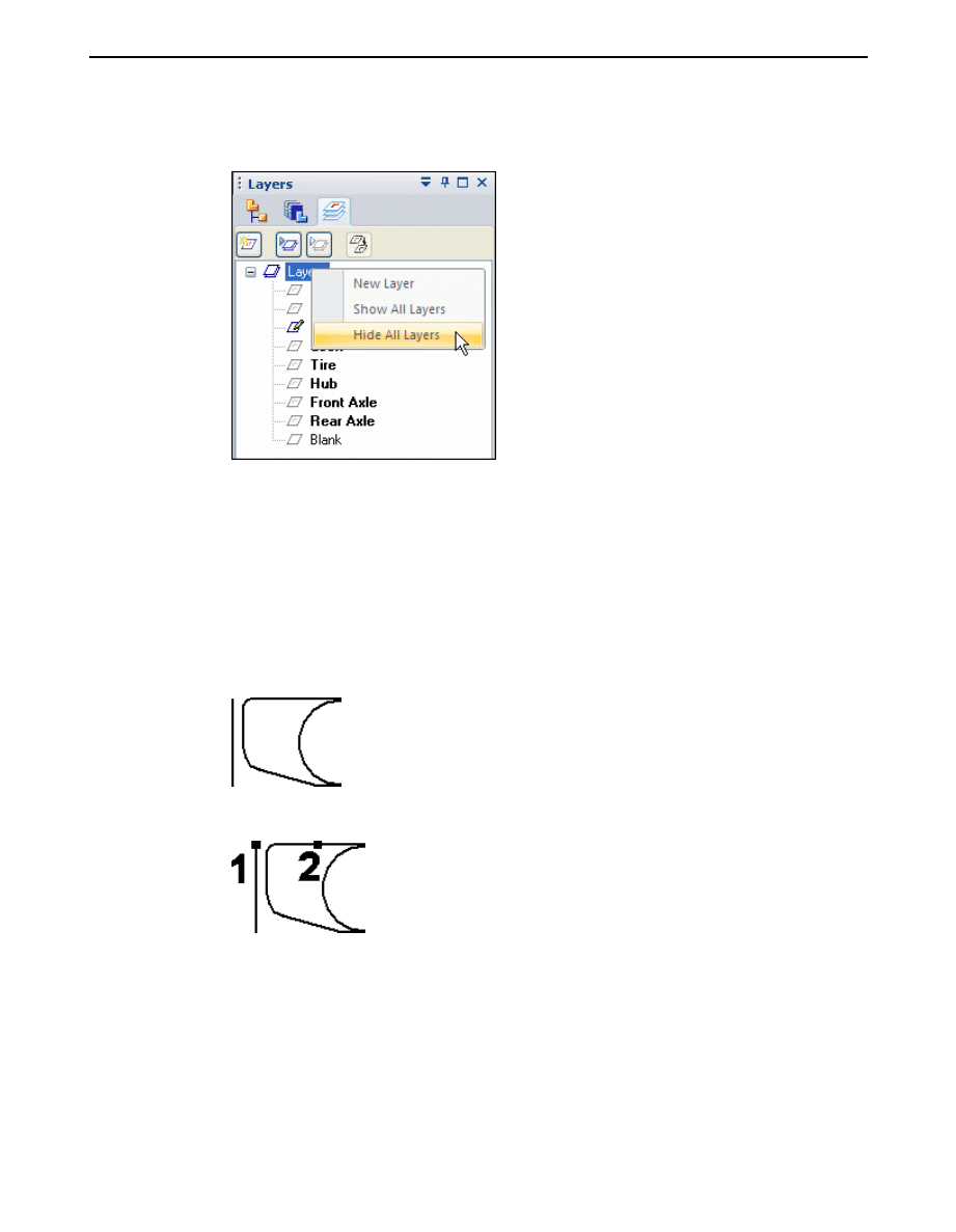
▸
Right-click Layers and click Hide All Layers.
Note
Geometry that has been previously added to virtual components cannot
be hidden by sketch layers and is not available to be added to additional
virtual components.
▸
On the Layers tab, show the layer Rear Axle.
▸
On the Assembly PathFinder tab, right-click the virtual component Hub and
click Edit Definition. Use a fence to select all the geometry on the layer Hub
and click Accept.
▸
Orient the axis using the points shown below, and click Finish.
▸
On the Layers tab, make the layer Tire active and hide the layer Hub.
A-10
Virtual components in assemblies
spse01690
Activity: Virtual component editor
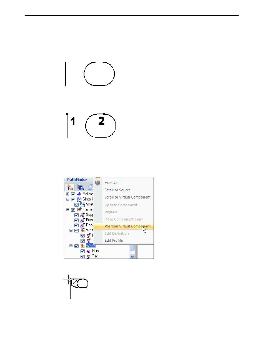
▸
On the Assembly PathFinder tab, right-click the virtual component Tire and
click Edit Definition. Use a fence to select all the geometry on the layer Tire
and click Accept.
▸
Orient the axis using the points shown below, and click Finish.
▸
On the Layers tab, show the layer Front Axle.
▸
On the Assembly PathFinder tab, right-click the second occurrence of the
assembly Wheel and click Position Virtual Component.
▸
Click the top of the vertical line that represents the front axle.
▸
On the Layers tab, make the layer Deck the active layer and hide all the other
layers.
spse01690
Virtual components in assemblies
A-11
A
Activity: Virtual component editor
▸
On the Assembly PathFinder tab, right-click the virtual component Deck, and
click Edit Definition. Use a fence to select all the geometry on the layer Deck,
and accept. Orient the axis using the two points shown, and then click Finish.
▸
On the Layers tab, show all the layers.
▸
Click Close Sketch to exit the sketch, then click Finish.
Create component sketches
Create component sketches in three existing parts to position the parts in the
virtual assembly.
▸
In the Parts Library tab of PathFinder, right-click small_motor.par and click
Open in Solid Edge. Browse to the location where the activity files are located.
A-12
Virtual components in assemblies
spse01690
Activity: Virtual component editor
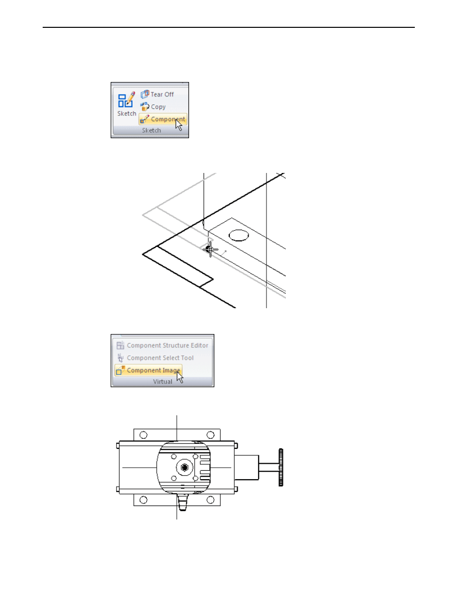
▸
On the Home tab, click the command Component Sketch.
▸
Create the sketch on a plane parallel to the top reference plane. Use the keypoint
shown to position the parallel plane.
▸
Click the Tools tab. In the Virtual group, click the Component Image command.
▸
Click Accept to add the highlighted geometry to the sketch.
spse01690
Virtual components in assemblies
A-13
A
Activity: Virtual component editor
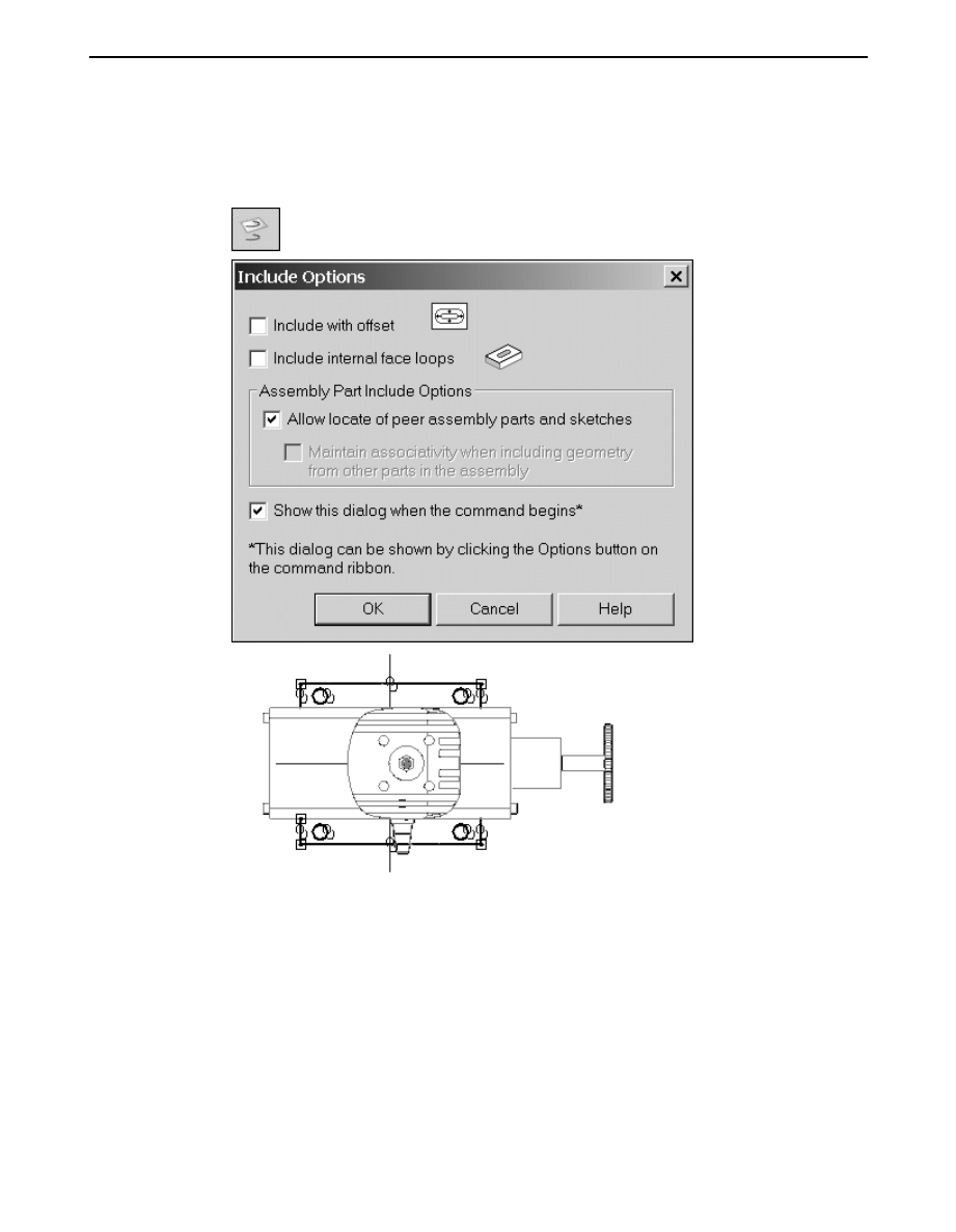
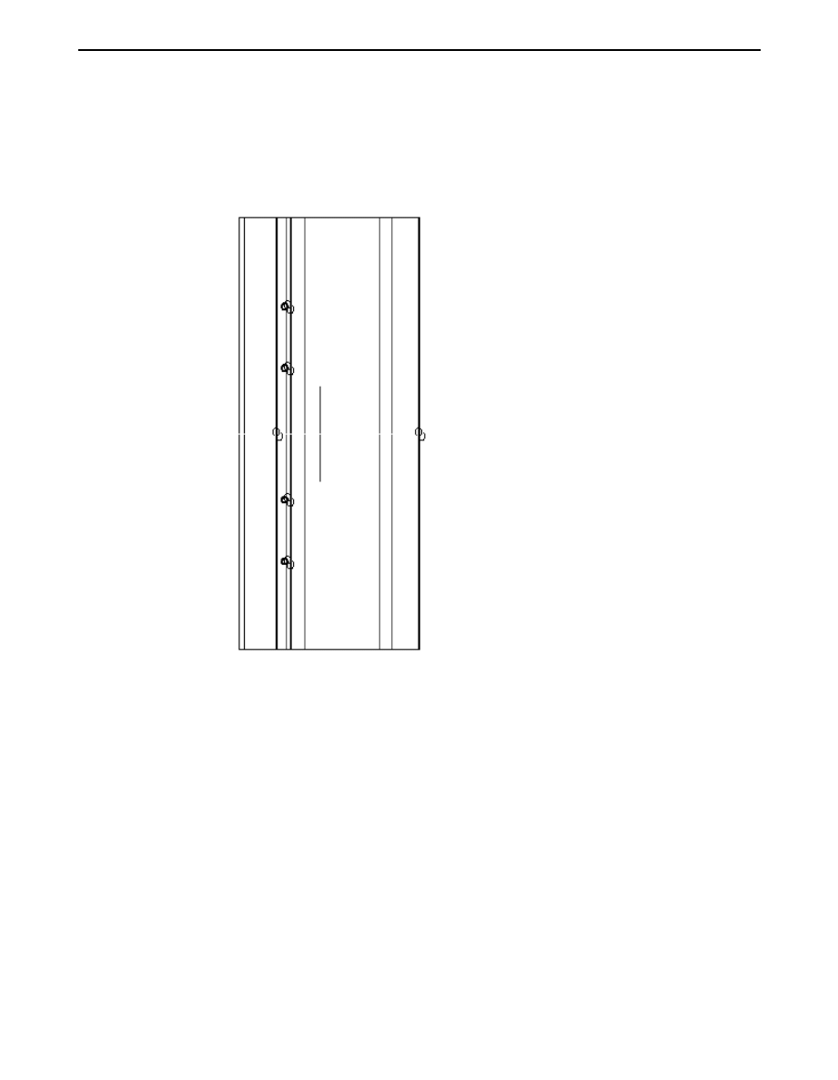
▸
On the Home tab, in the Draw group, click the Include command and include
the edges shown. The Include command is needed to add precise geometry to
the sketch in order to accurately position the part.
▸
Click Close Sketch, then click Finish. Save and close the file.
▸
In the Parts Library tab of PathFinder, right-click wide_seat.par and click Open
in Solid Edge.
A-14
Virtual components in assemblies
spse01690
Activity: Virtual component editor
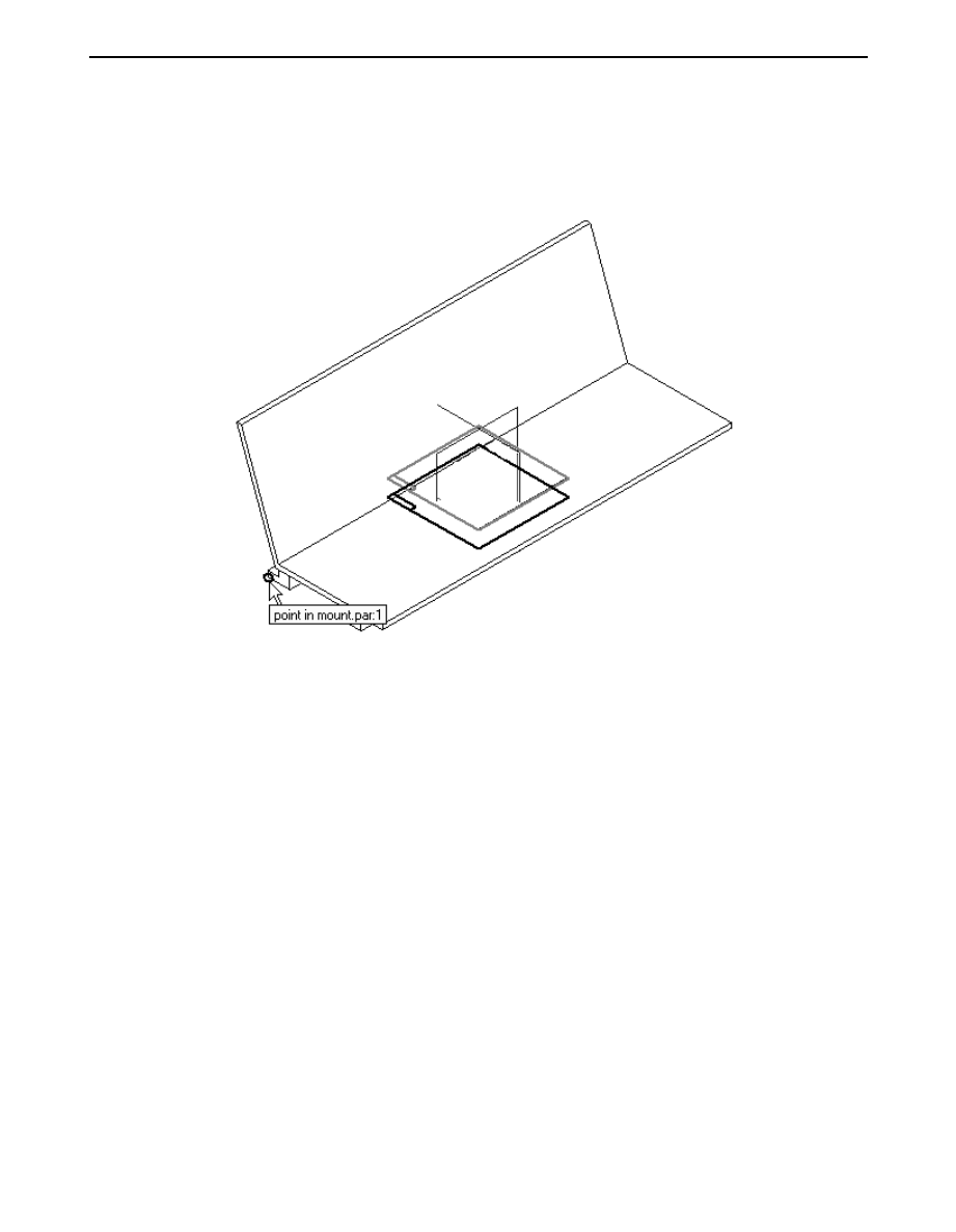
▸
Create a component sketch on a plane parallel to the top reference plane. Use
a keypoint on the bottom face of the mount as shown to position the sketch’s
reference plane.
spse01690
Virtual components in assemblies
A-15
A
Activity: Virtual component editor
▸
Click the Component Image command. Accept the highlighted geometry, and
then select the Include command and include the cutouts and edges shown.
Click Close Sketch, then Finish to complete the component sketch. Save and
close the file.
A-16
Virtual components in assemblies
spse01690
Activity: Virtual component editor
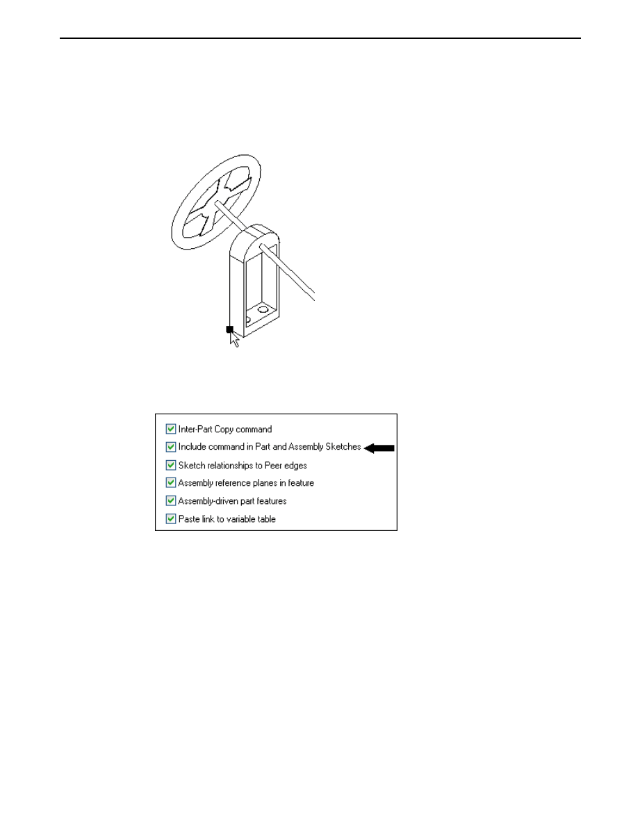
▸
In the Parts Library, right click steering.asm and click Open in Solid Edge.
Activate all the parts in the assembly. Create a component sketch on a plane
parallel with the top reference plane. Use the keypoint shown to position the
reference plane.
▸
Click the Application button. Click Solid Edge Options and then click the
Inter-Part tab. Make sure the Include command in part and assembly sketches
box is checked.
spse01690
Virtual components in assemblies
A-17
A
Activity: Virtual component editor
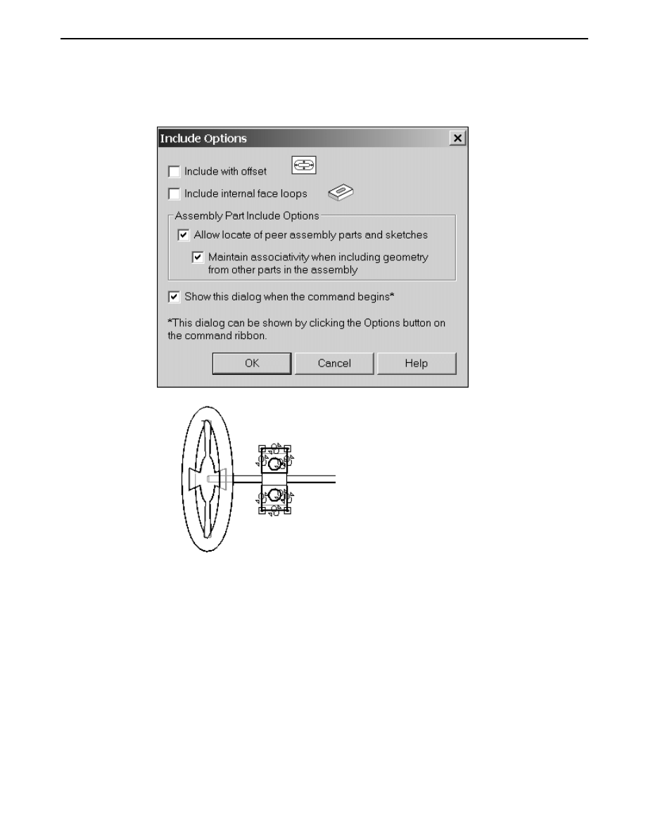
▸
Drag a box to Include all the geometry shown in the sketch. Set the include
options as shown.
▸
Click Close Sketch to exit the sketch, then click Finish.
▸
Save and close the file. This returns you to the assembly.
A-18
Virtual components in assemblies
spse01690
Activity: Virtual component editor
Position the component sketches in the existing parts as part of the
virtual component structure
▸
Open the Component Structure Editor and drag the three Solid Edge files where
you created component sketches into the assembly, then click OK.
spse01690
Virtual components in assemblies
A-19
A
Activity: Virtual component editor
▸
The parts with the component sketches will now be positioned in the virtual
assembly. On the Assembly PathFinder, right-click Sketch_1 and then click
Edit Profile.
▸
On the Layers tab, hide the layers named Master_Layout and Dimensions, if
they are not already hidden.
▸
In Assembly PathFinder, right-click the virtual component small_motor.par
and click Position Virtual Component.
A-20
Virtual components in assemblies
spse01690
Activity: Virtual component editor
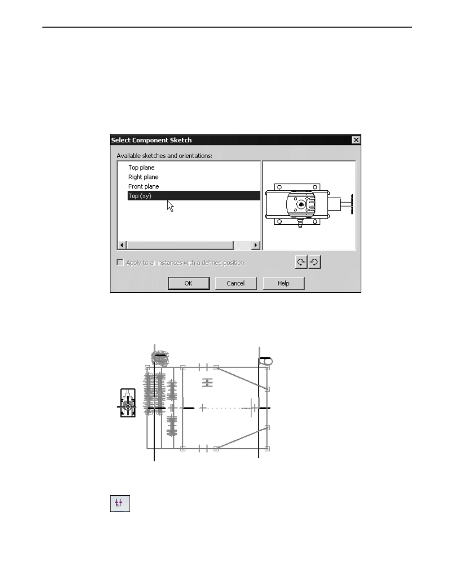
▸
Select the plane shown. The component sketch will show in the preview area.
Click OK.
Note
You will know you have selected the correct plane when the preview
shows your component sketch.
▸
Observe the prompts. On the keyboard, press A to rotate the motor into
the position shown. Click to the left of the sketch and place the component
approximately where shown.
▸
Click the Home tab. In the Relate group, turn off Relationship Handles.
spse01690
Virtual components in assemblies
A-21
A
Activity: Virtual component editor
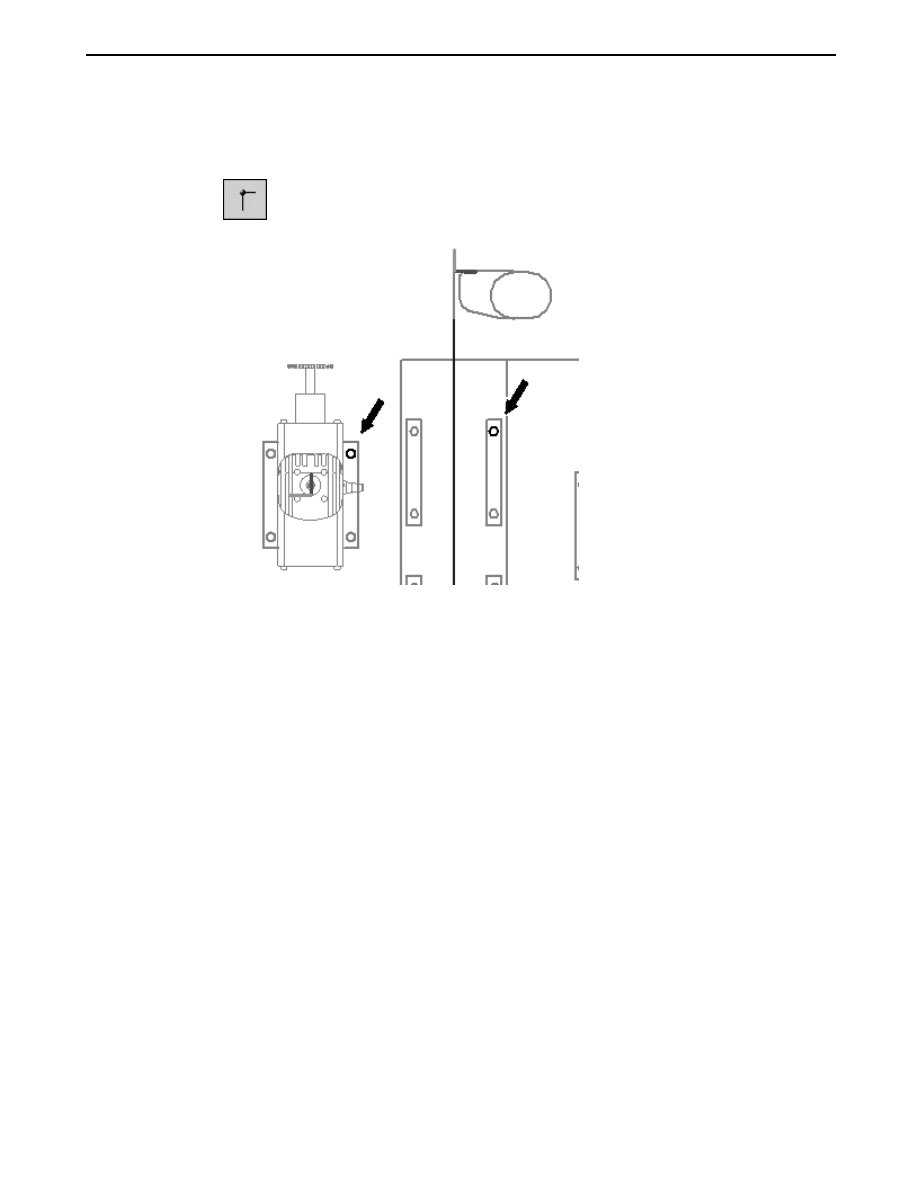
▸
In the Relate group, click the Connect command, and connect the center of the
circles shown below.
▸
Click the select tool. In Assembly PathFinder, right-click the virtual component
wide_seat.par and click Position Virtual Component.
A-22
Virtual components in assemblies
spse01690
Activity: Virtual component editor
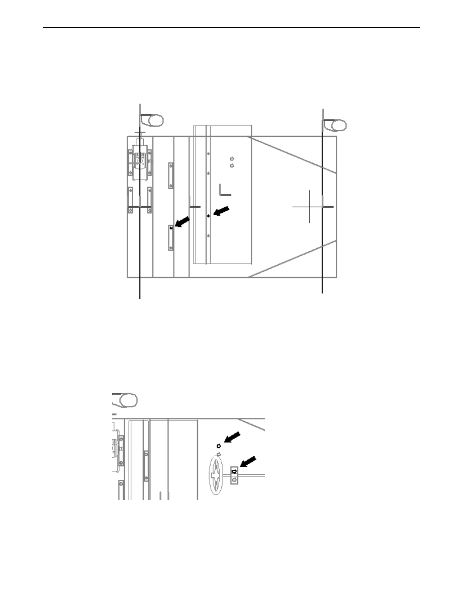
▸
Click the Select tool. Use the same procedure to position the seat as you used
to position the component motor. Use the Connect command to position the
seat using the circles shown.
▸
Click the Select tool.
▸
In Assembly PathFinder, right-click the virtual component steering.asm and click
Position Virtual Component.
▸
Use the same procedure used to position the seat to position the steering wheel.
Use the Connect command to position the steering wheel using the circles shown.
▸
Click Close Sketch to exit the sketch. Then click Finish. Save the assembly.
spse01690
Virtual components in assemblies
A-23
A
Activity: Virtual component editor
Publish the virtual assembly
▸
On the Home tab, in the Assemble group, click the command Publish Virtual
Components. This will create real components from the virtual components.
▸
Set the path to correspond to the directory structure you have been using for
this activity and click Publish.
A-24
Virtual components in assemblies
spse01690
Activity: Virtual component editor
▸
Notice that now there are real parts Assembly PathFinder. Activate all the parts.
Create the frame from the sketch geometry
▸
In Assembly PathFinder, right-click support.par and then click Open in Solid
Edge part.
spse01690
Virtual components in assemblies
A-25
A
Activity: Virtual component editor
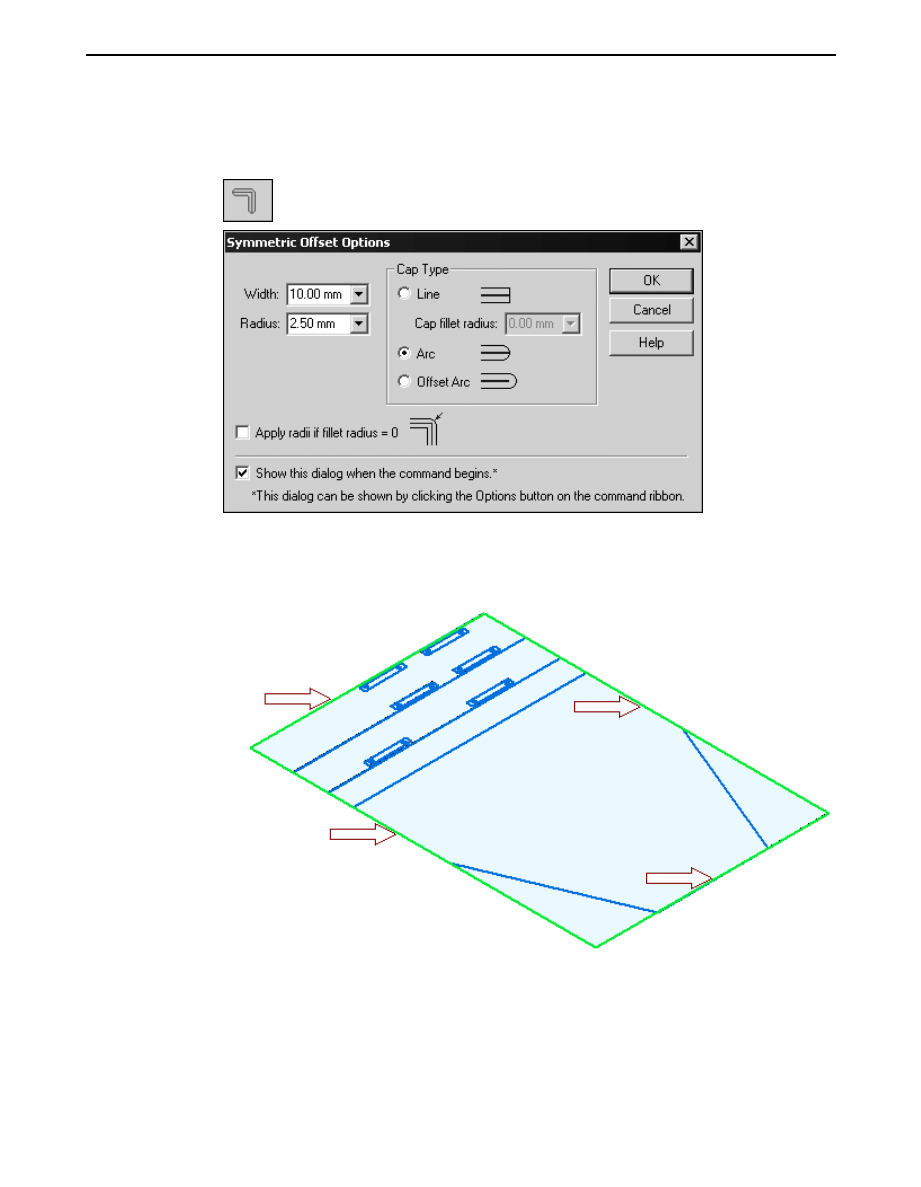
▸
Choose the Home tab
→Draw group→Symmetric Offset command, and enter
the values shown.
▸
Set the type to chain.
▸
Select the rectangular perimeter of the sketch as shown below.
A-26
Virtual components in assemblies
spse01690
Activity: Virtual component editor
▸
Accept the selection.
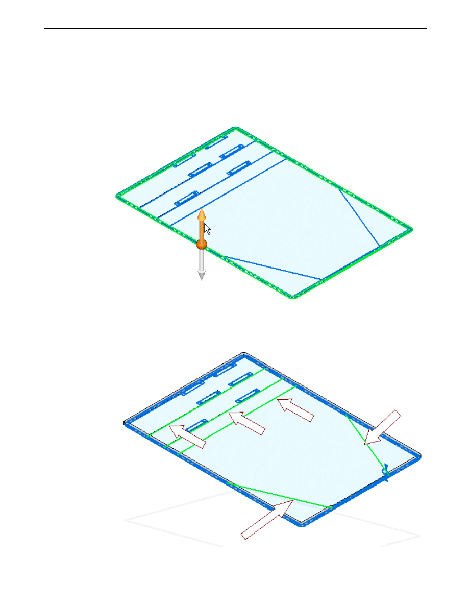
▸
Click the Select tool and use QuickPick to select the region shown. Extrude
the selection 8 mm in the +Z direction.
▸
Click the Symmetric Offset command. Using the same values as before, select
the 5 lines shown below. Accept the selection.
spse01690
Virtual components in assemblies
A-27
A
Activity: Virtual component editor
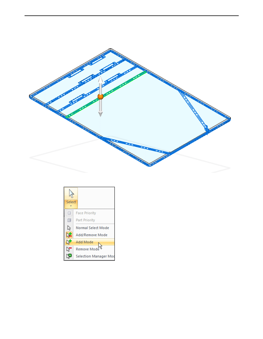
▸
Click the Select tool. Select the region shown below.
▸
Set the Selection mode to add mode as shown below.
A-28
Virtual components in assemblies
spse01690
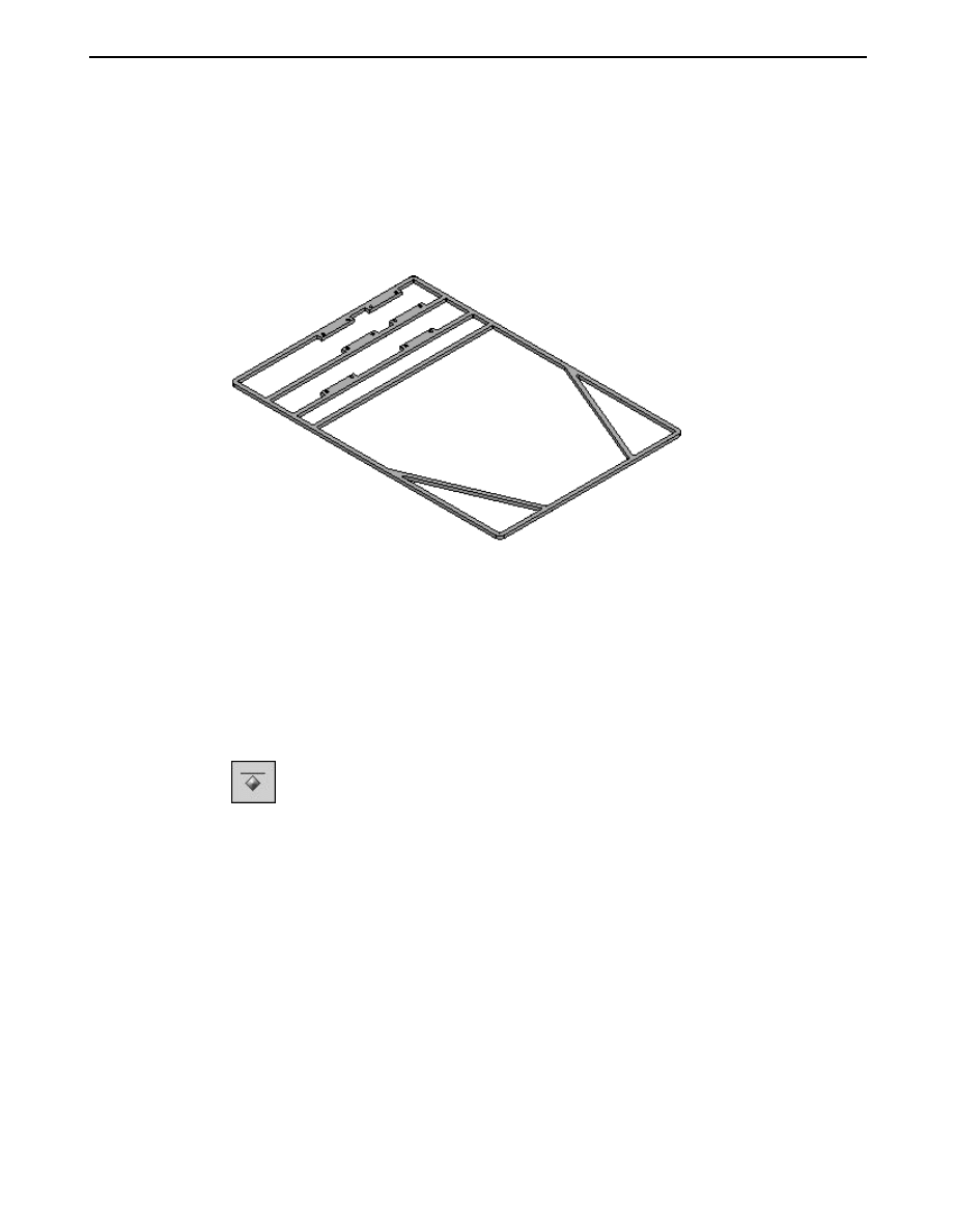
Activity: Virtual component editor
▸
Continue selecting the additional regions required to extrude the remainder of
the frame and extrude them 8 mm in the +Z direction.
Note
Use QuickPick to select the regions easily.
▸
Save and close the file to return to the assembly.
Model the front axle
▸
On Assembly PathFinder, select frame.asm and then choose Home tab
→Relate
group
→Ground relationship. This will ground the top level of the frame such
that additional relationships can be added to the remaining parts without
moving the frame.
▸
Assembly PathFinder, right-click the part Front Axle.par and then click Edit.
spse01690
Virtual components in assemblies
A-29
A
Activity: Virtual component editor
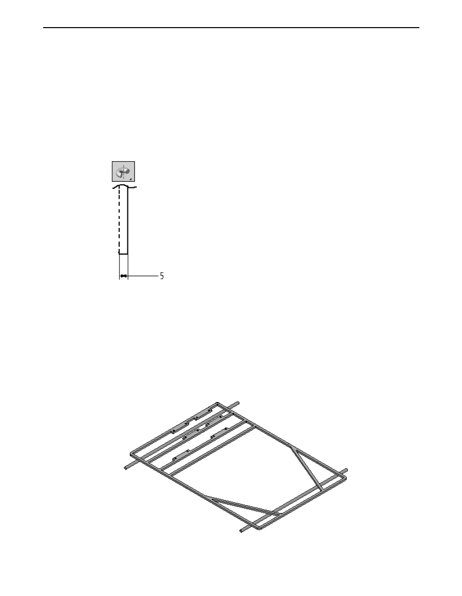
▸
Use the Coincident Plane command to create a plane parallel to, and 5 mm
below, the x-y plane. Use the Include command or the Project to Sketch command
to project the line of the front axle onto the plane.
▸
Draw a rectangle with a short side that is 5 mm wide and as long as the front
axle sketch element. Lock the sketch onto the plane you created.
▸
Use the Revolve command to create an axle with radius of 5 mm by selecting the
rectangle you created. Use the included line in the front axle sketch to represent
the center-line of the 3D axle. Sweep the revolution 360
o
to create the axle.
▸
After creating the revolved protrusion, click Close and Return.
Model the rear axle
▸
On the Assembly PathFinder, right-click the part Rear Axle.par and then click
Edit. Create a revolved protrusion on a parallel plane 5 mm below the x-y plane,
as you did with the Front Axle in previous steps. The radius of the protrusion
is 5 mm.
Click Close and Return to return to the assembly.
A-30
Virtual components in assemblies
spse01690
Activity: Virtual component editor
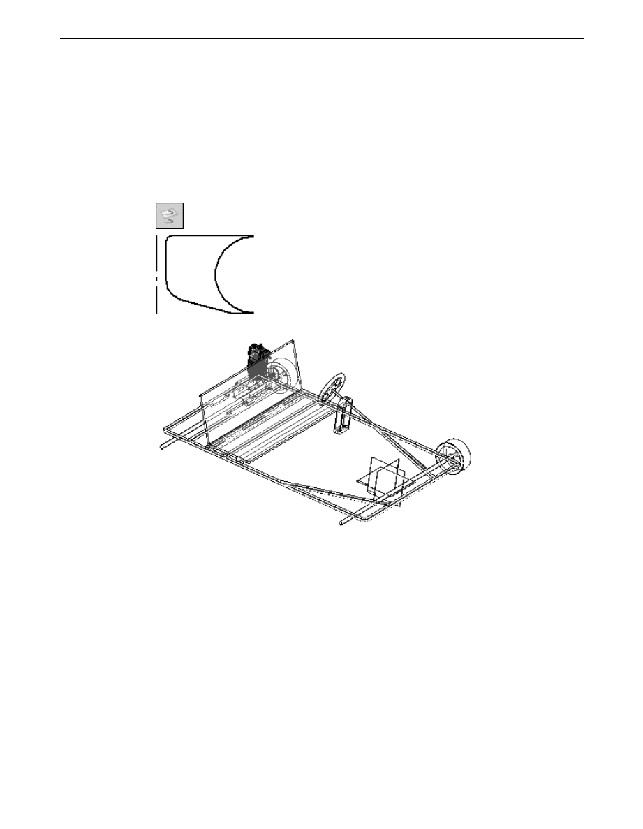
Model the wheel hub
▸
On the Assembly PathFinder, right-click the part Hub.par and click Edit.
▸
Create a 360° revolved protrusion on a parallel plane 5 mm below the x-y plane.
Define the axis of revolution using the dashed line as shown. Use the include
command with the wireframe chain option. Click Finish to complete the revolved
protrusion, then click Save and close to return to the assembly.
Model the tire
▸
On the Assembly PathFinder, right-click the part Tire.par and click Edit.
spse01690
Virtual components in assemblies
A-31
A
Activity: Virtual component editor
▸
Create a 360° revolved protrusion on a parallel plane 5 mm below the x-y plane.
Define the axis of revolution using the dashed line as shown. Click finish to
complete the revolved protrusion, then click close and return.
Model the sheet metal deck
▸
On the Assembly PathFinder, right-click the sheet metal part Deck.psm and
click edit.
▸
Select the region shown and create the deck. The circles will be the cutout in
the deck. The extent of the tab will be below the profile plane and the sheet
metal thickness will be 3.00 mm.
▸
Click close and return.
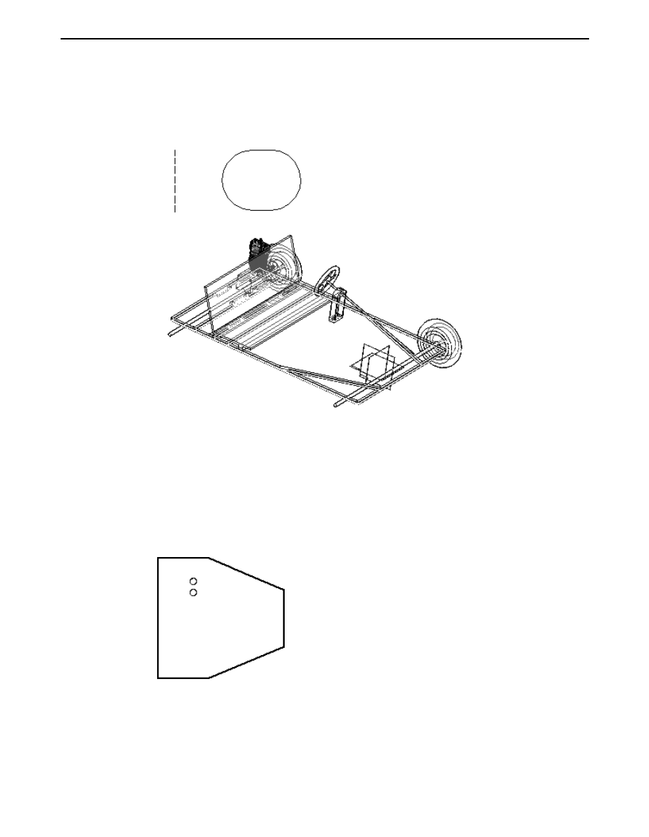
Mirror the wheels
▸
On the Assembly PathFinder show the reference planes.
A-32
Virtual components in assemblies
spse01690
Activity: Virtual component editor
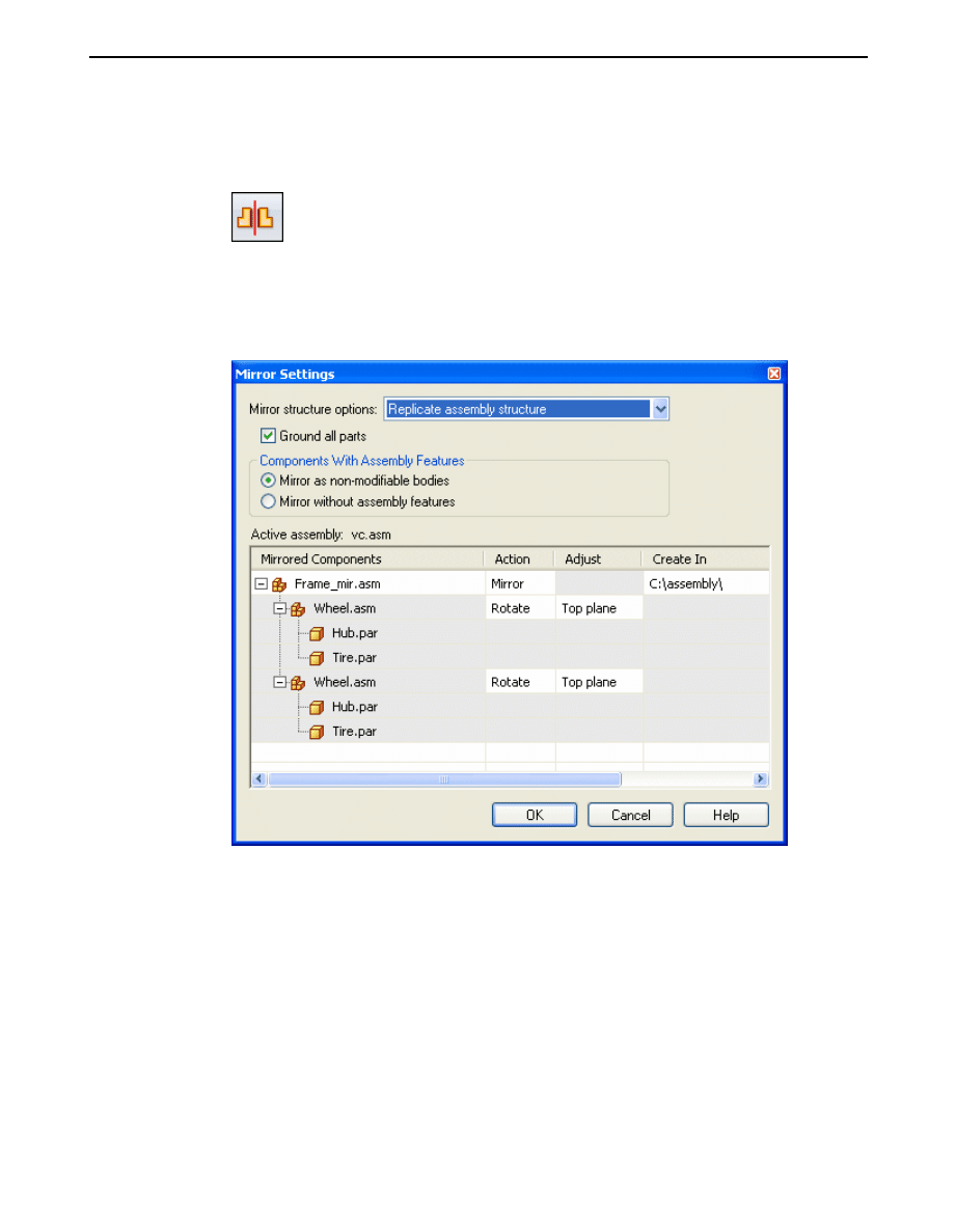
▸
On the Home tab in the Pattern group, click the mirror command. Select the x-z
plane to mirror about.
▸
In the Assembly PathFinder, select the two assemblies named Wheel.asm, and
on the command bar, click accept.
▸
Set the options shown and then click ok, then click finish.
▸
Assembly relationships can be edited to further position and constrain the parts.
Save and close this file. This concludes this activity.
Activity summary
In this activity you learned how to create a virtual assembly structure using virtual
components. Sketch geometry in the assembly file was assigned to virtual part
files and once published, the sketch geometry was moved into those files and used
to create parts. Existing parts were placed in the virtual structure and positioned
using component sketches. This is a top down approach to laying out and modeling
complex assemblies.
spse01690
Virtual components in assemblies
A-33
Document Outline
- Contents
- Proprietary and restricted rights notice
- Contents
- 1. Introduction
- 2. Creating and publishing Virtual Components
- 3. Activity: Virtual component editor
- 4. Lesson review
- Answers
- 5. Lesson summary
- Activity: Virtual component editor
- Define the virtual assembly structure
- Assign geometry to parts
- Create component sketches
- Position the component sketches in the existing parts as part of the virtual component structure
- Publish the virtual assembly
- Create the frame from the sketch geometry
- Model the front axle
- Model the rear axle
- Model the wheel hub
- Model the tire
- Model the sheet metal deck
- Mirror the wheels
- Activity summary
Wyszukiwarka
Podobne podstrony:
Islamic Microfinance A Missing Component in Islamic Banking
Barłożek, Nina Teachers’ emotional intelligence — a vital component in the learning process Nina Ba
Modanese Paradox of Virtual Dipoles in the Einstein Action (2000)
Islamic Microfinance A Missing Component in Islamic Banking
Measuring virtual machine detection in malware using DSD tracer
Replacing parts in an assembly
AES Recommended Practice Specification Of Loudspeaker Components Used In Professional Audio And Soun
Virtual(ly) Law The Emergence of Law in LambdaMOO Mnookin
Maffra, Gattass Propagation of Sound in Two Dimensional Virtual Acoustic Environments
Lokki T , Gron M , Savioja L , Takala T A Case Study of Auditory Navigation in Virtual Acoustic Env
Possibility of acceleration of the threshold processes for multi component gas in the front of a sho
Education in Poland
Participation in international trade
in w4
assembler
Metaphor Examples in Literature
Symmetrical components method continued
Die Baudenkmale in Deutschland
więcej podobnych podstron