
Subject
Page
Purpose of the System. . . . . . . . . . . . . . . . . . . . . . . . . . . . . . . . . . . . . . .3
Power Module Functions. . . . . . . . . . . . . . . . . . . . . . . . . . . . . . . . . . . . . 3
Detailed View of Power Module. . . . . . . . . . . . . . . . . . . . . . . . . . . . . . . . 5
Components of the Power Module and Voltage Supply Circuit. . . . . . . . . . 6
Power Supply Circuit . . . . . . . . . . . . . . . . . . . . . . . . . . . . . . . . . . 7
Inputs. . . . . . . . . . . . . . . . . . . . . . . . . . . . . . . . . . . . . . . . . . . . . 12
Outputs Connected to Electronic Battery Switch. . . . . . . . . . . . . . 13
Outputs Not Connected to Electronic Battery Master Switch. . . . . 13
Power Module Functions. . . . . . . . . . . . . . . . . . . . . . . . . . . . . . . . . . . . 15
Optimum Charging. . . . . . . . . . . . . . . . . . . . . . . . . . . . . . . . . . . .15
Load-Circuit Peak Reduction. . . . . . . . . . . . . . . . . . . . . . . . . . . . 17
Shut-down of Consumers in the Event of Low Voltage. . . . . . . . . .19
16 min. Shut Down of Consumer Circuits. . . . . . . . . . . . . . . . . . . 20
Shut Down of Auxiliary Consumers. . . . . . . . . . . . . . . . . . . . . . . .20
Auxiliary Consumers and Terminal R. . . . . . . . . . . . . . . . . . . . . . . 21
Auxiliary Consumers and Terminal 0. . . . . . . . . . . . . . . . . . . . . . . 21
Closed-Circuit Current Monitoring. . . . . . . . . . . . . . . . . . . . . . . . .22
Distribution Mode. . . . . . . . . . . . . . . . . . . . . . . . . . . . . . . . . . . . .24
Electronic Fuse. . . . . . . . . . . . . . . . . . . . . . . . . . . . . . . . . . . . . . 24
Central Battery Voltage Notification. . . . . . . . . . . . . . . . . . . . . . . .25
Rear Window Heater. . . . . . . . . . . . . . . . . . . . . . . . . . . . . . . . . . 25
Interior Lighting. . . . . . . . . . . . . . . . . . . . . . . . . . . . . . . . . . . . . . 25
Trunk Lid and Fuel filler Flap Control. . . . . . . . . . . . . . . . . . . . . . . 25
Data Memory. . . . . . . . . . . . . . . . . . . . . . . . . . . . . . . . . . . . . . . .26
Emergency Mode Functions. . . . . . . . . . . . . . . . . . . . . . . . . . . . .26
Check Control Messages. . . . . . . . . . . . . . . . . . . . . . . . . . . . . . .27
Review Questions. . . . . . . . . . . . . . . . . . . . . . . . . . . . . . . . . . . . . . . . . 30
Table of Contents
POWER MODULE

2
Power Module
POWER MODULE
Model: E65 - 745i
Production Date: 11/2001- Start of Series Production
Objectives:
After completing this module you should be able to:
•
Understand the purpose of the Power Module in the E65.
•
Identify the locations of the various components in the voltage supply system.
•
Describe the operation and purpose of the battery switch.
•
Explain how the Power Module regulates the vehicle generator.
•
Understand the vehicle sleep mode sequence and monitoring function.
•
Describe what procedure must be done after replacing a vehicle battery.

3
Power Module
Purpose of the System
The Power Module (PM) is one of the innovative new developments on the E65. The job
of the Power Module is to ensure that the battery charge level is maintained when the
engine is running and when the vehicle is at rest. The Power Module is also responsible for
maintaining the power supply (in the event of faults in the electrical system) to important
vehicle systems by disconnecting lower priority circuits.
Power Module Functions
•
Optimum charging.
•
Load-circuit peak reduction.
•
Shut-down of auxiliary consumer circuits in the event of low voltage.
•
Closed circuit current monitoring.
•
Distribution mode.
•
Automatic electrical system isolation.
•
Load cutout.
•
Electronic fuses.
•
Central battery voltage notification.
•
Rear window defogger output.
•
Interior lighting control.
•
Trunk lid and fuel filler flap control.
•
Data memory storage.
•
Emergency-mode functions.
•
Check Control messages.
•
Diagnosis.
4
Power Module
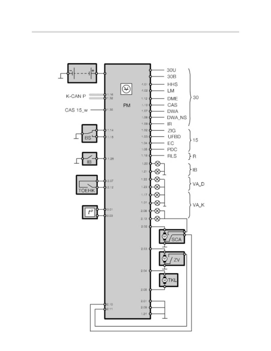
Inputs/Outputs
KT-8350
Battery Switch
Battery
K-CAN
Periphery
Wake-up input
from CAS
Interior light
switch
External trunk
release button
Battery Temp.
Sensor
Terminal 30
outputs
HHS=Rear window
defogger.
LM=Lamp Module.
DME=ECU
CAS=Car Access
System
DWA=Alarm C.U.
DWA NS=Sirene
IR=Not used in U.S.
Terminal 15
outputs
ZIG=Cig. lighter relay
UFBD=Universal
remote control.
EC=Electrochromatic
mirrors.
PDC=Park Distance
Control.
Terminal R
outputs
RLS=Rain/Light Sensor
(IB) Interior
Lighting
(VA-D)
Consumer
Isolation
Circuit/Roof
(VA-K)
Consumer
Isolation
Circuit/Body
SCA
Soft Close
Actuator (Trunk)
ZV
Central lock
Actuator (trunk)
TKL
Central lock
Actuator
(Fuel
door)
5
Power
Module
Detailed
view
of
Power
Module
KT
-8349
X1856 32 Pin connector
X1857 13 Pin connector
X1858 3 Pin
Connector
(Temp. Sensor)
X1859 2 pin
connector
(HHS and LM)
6
Power Module
Components of the Power Module and Voltage Supply Circuit
•
Power Supply circuit
•
Fuses
•
Power Module
•
Electronic battery master switch
•
High-current sockets
•
Inputs
•
Outputs connected to electronic battery master switch
•
Outputs not connected to electronic battery master switch
•
Electronic control unit
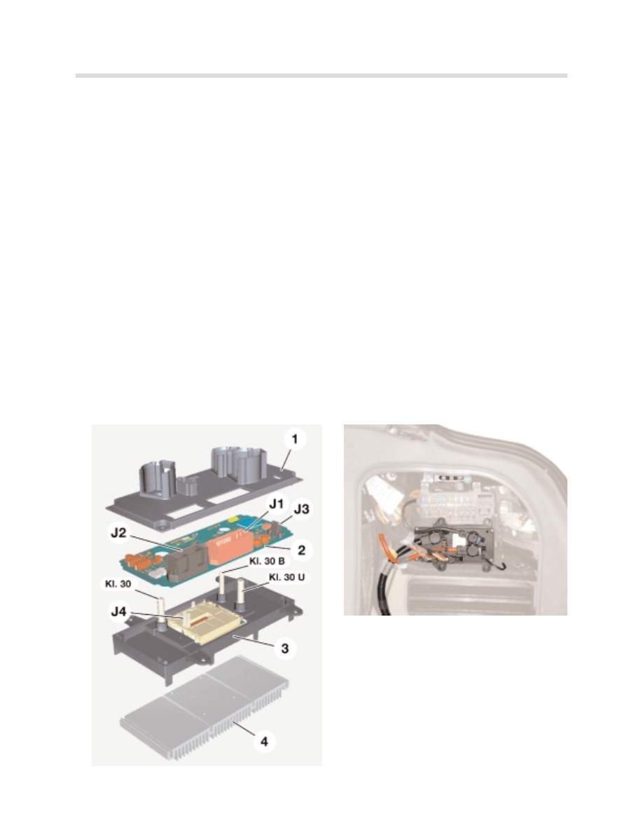
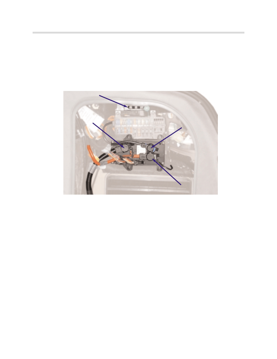
Location and Construction of Power Module
The power module on the E65 is located on the right-hand side of the luggage
compartment.
1 Cover plate
2 Electronics
3 Electronic Battery Master switch
4 Heat sink
KT-7741
KT-8355
7
Power Module
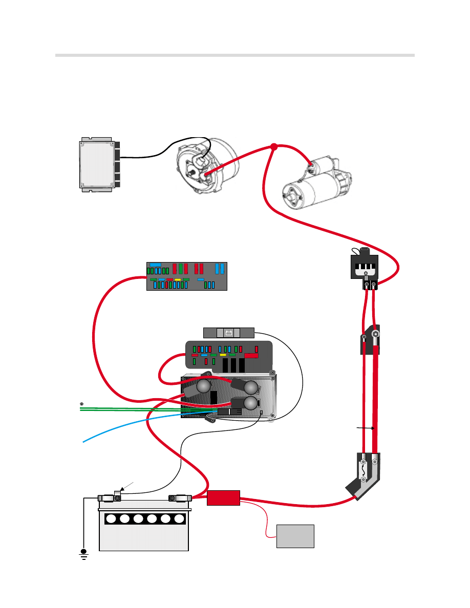
Power Supply Circuit
The power supply for the general electrical system is controlled by the Power Module.
The high amperage fuses in the engine compartment, the generator and the starter motor
are connected directly to the battery and not supplied by the Power Module.
-
+
110 Ah
ON
OFF
BST
DME
GENERATOR
STARTER
B+ TERMINAL
ENGINE COMP.
FUSES
BSD
FUSES IN GLOVE BOX
30U
30B
BATTERY SWITCH
FUSES IN TRUNK
TEMP.
SENSOR
K-CAN-P
250 AMP
FUSE IN TRUNK
15w FROM CAS
120mm ALUMINUM
FLAT CABLE
JUNCTION BLOCK
RIGHT SIDE INNER
BULKHEAD
POWER MODULE
SBSR
420805
2
8
Power Module
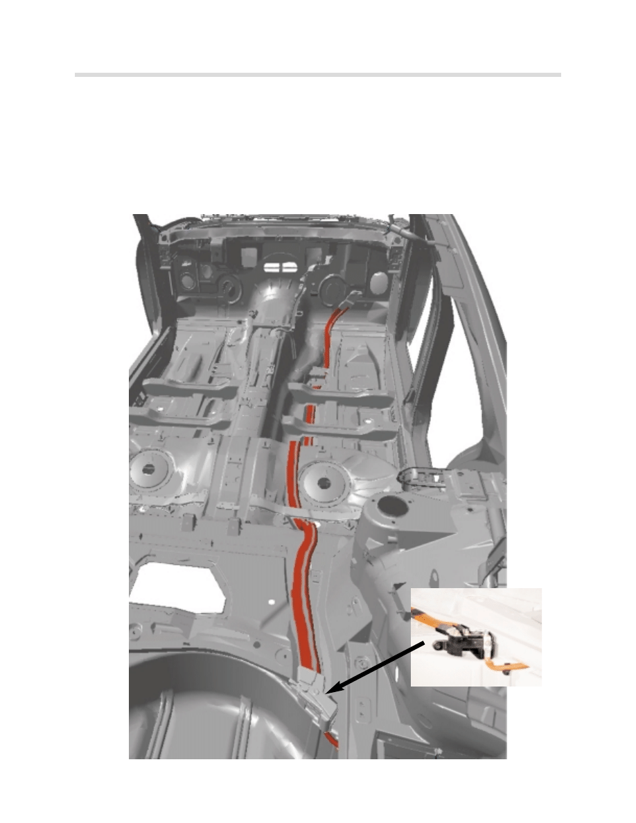
Positive Battery Cable
An aluminum battery cable in the E65 is used for the first time by a BMW automobile. The
cable is flat (120mm
2
) and runs along the vehicle interior from a junction box ahead of the
spare tire well to the interior side of the front bulkhead. A smaller copper cable runs paral-
lel to it in the vehicle interior. That smaller cable is supplied via a 250 amp fuse located
inside the same junction box that feeds the aluminum cable.
Junction point with
250 Amp fuse.
9
Power Module
Battery
The E65 is fitted with a single maintenance free battery (12 V/110 Ah). The battery like other
BMW models is located in the right side of the trunk below the vehicle jack.
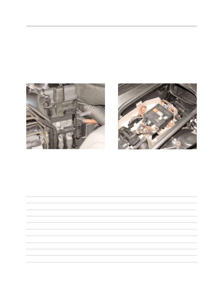
Fuses
The locations of the fuses are as follows:
420801
420802
•
Next to jump-start connection point
• F-101 100A IVM (Engine/DME Supply)
• F-102 50A Secondary Air Pump
• F-103 80A Auxiliary Fan
• F-104 100A IVM (Engine/DME Supply)
Note* Fuses 101-104 is a bus strip that is
replaced as complete unit if one circuit is
blown.
•
Right side engine compartment inside
the Integrated Voltage supply Module (IVM)
Engine Compartment
10
Power Module
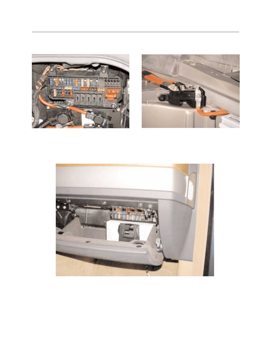
Luggage Compartment Fuses
·
Apart from the fuses referred to above, certain control units have integrated electronic fuses
which protect components connected directly to the control unit.
420803
0610 battery
•
Right side of luggage compartment
• Fuses 51 through 84
Interior Fuses
•
Junction point with 120mm
2
aluminum
flat cable.
• 250 Amp fusible link (F-200).
•
Inside of glove box
• Fuses 1-44

11
Power Module
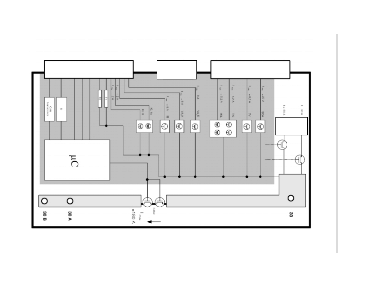
Electronic Battery Master Switch
The electronic battery master switch is made up of 4 MOS-FET output stages (S Bat) and
connects the input terminal 30 with the outputs KL 30U and KL 30B on the Power Module.
The following functions are controlled by means of the Power Module according to the
position of the battery switch:
•
Storage mode
•
Closed circuit current monitoring
•
Electronic fuses
•
Automatic electrical system isolation
High-Current Terminals (RADSOK
)
New high-current terminals are used for the first time. The high-current terminals are on the
input terminal 30 and the outputs terminal 30U and terminal 30B. These contacts are capa-
ble of carrying current peaks (short term) of 220 A.
Advantages:
•
Continuous load capacity of up to 100 A
•
Excellent and consistent current conduction over long periods
•
Low contact resistance
•
Low voltage drop even with large temperature rise
•
Consistently good spring characteristics
•
Contacts are self-cleaning (contacts have a slight amount of allowable movement)
The contacts are coated in a silver alloy. Compared with tin, nickel, gold and copper, silver
has the lowest specific electrical resistance.
In spite of the high currents, the high-current sockets are not soldered to the cable as a
special crimping technique ensures an excellent connection.
12
Power Module
Inputs
Terminal 30
The battery positive terminal is connected directly to the load input of the Power Module.
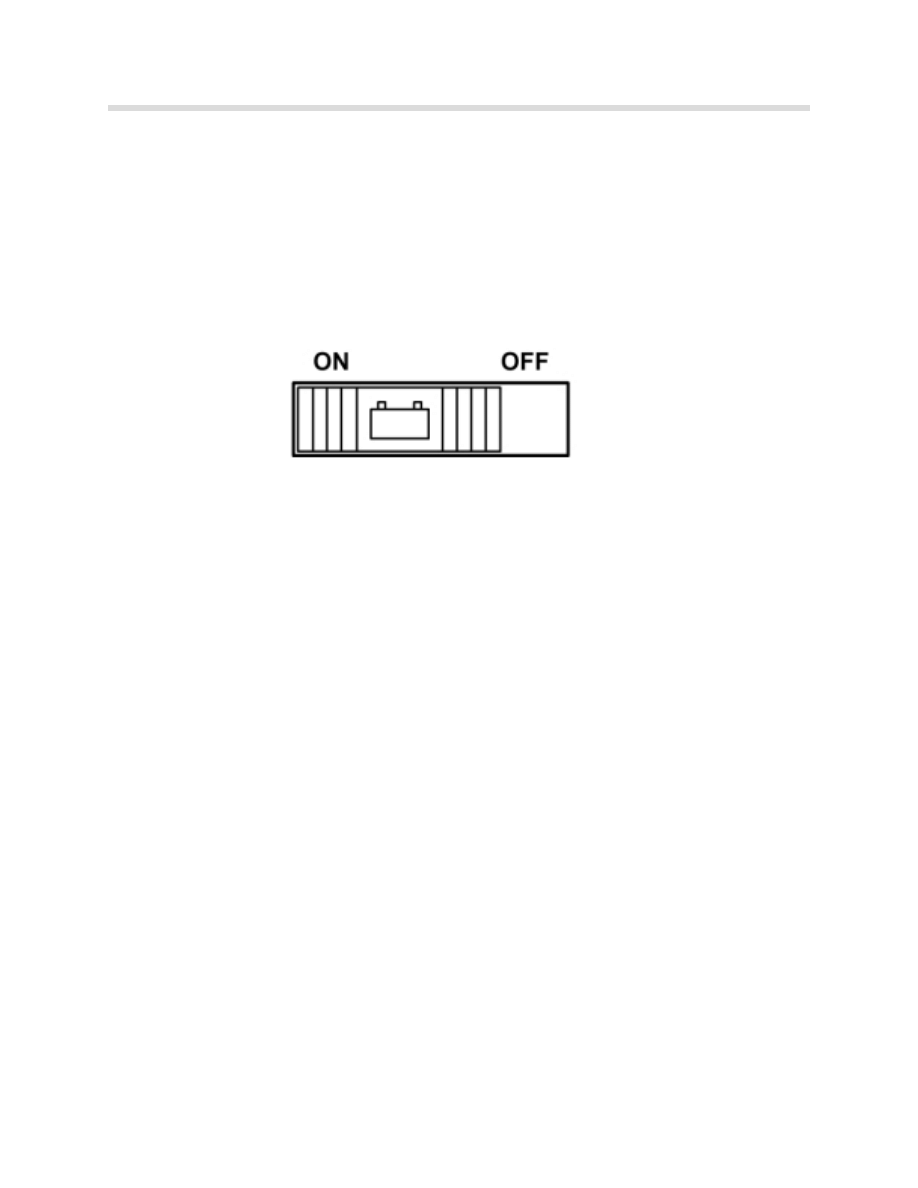
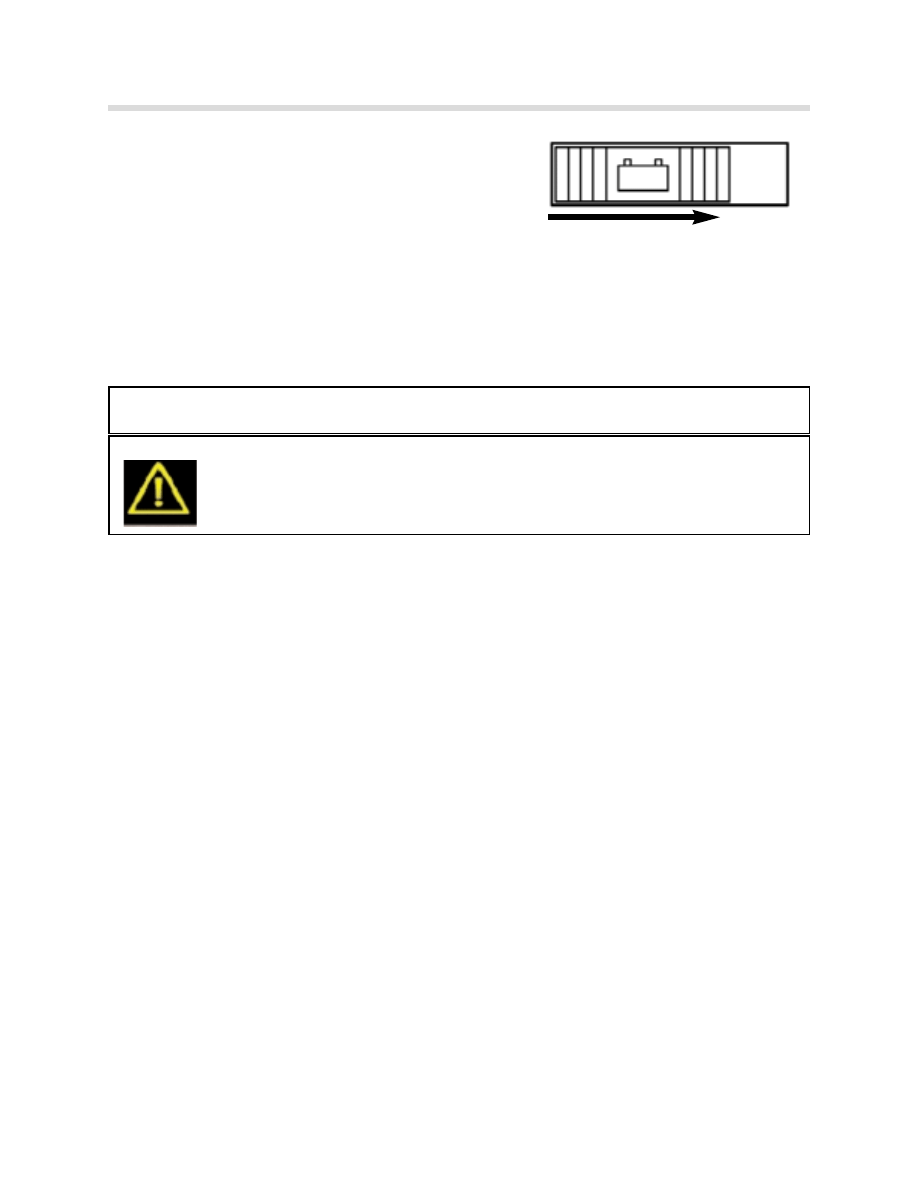
Battery Switch
The battery switch (BS) offers the vehicle owner and the service department the choice
between the settings ON ("closed circuit current monitoring") and OFF ("storage mode"). It
is located above the PM on the right hand side of the luggage compartment.
Interior Lighting Button
This controls the interior lighting and is located on the front interior lighting unit. The possi-
ble settings are "Automatic control", "On" , "Off" and “Workshop mode” (hold for 3 sec-
onds).
Exterior Trunk Lid Release Button (TOEHK)
This button is a direct input to the Power Module. The trunk lid is released by means of the
button on the outside of the trunk lid.
Trunk Lock Actuator Switch
The switch in the trunk lock actuator is used to inform the Power Module as to the position
of the lock actuator and to synchronize the SCA. it also controls the luggage compartment
lighting, the monitoring of the alarm system and the trunk lid warning light.
SCA Contact
This input is used to signal the PM that the SCA has rotated 180
0
. (used to switch off the
electric motor)
15_w (wake-up)
This is a redundant signal from the Car Access System which wakes up the Power Module.
Battery Temperature Sensor
Measures the temperature directly on the battery negative terminal. This information is
used for the "optimum charging" function. The measuring range is -25
O
C to +75
O
C.
K-CAN Periphery
Enables communication with the vehicle network.
KT-8288
13
Power Module
Outputs Connected to Electronic Battery Master Switch
Terminal 30U
Supplies the fuse box in the luggage compartment.
Terminal 30B
Supplies the fuse box in the glove compartment.
Outputs Not Connected to Electronic Battery Master Switch
The following outputs are supplied by the PM separately from the electronic battery master
switch.
•
Rear window heater (HHS)
•
Light Module (LM)
•
Car Access System (CAS)
•
DME
•
Alarm system (DWA)
•
Emergency power siren (SINE)
•
Cigarette lighter (ZIG)
•
Electrochromatic mirrors (EC)
•
Park Distance Control (PDC)
•
Rain/light sensor (RLS)
•
Interior lighting (IB)
•
Central locking trunk lid drive (ZV)
•
Central locking, fuel filler flap (ZV)
•
Trunk lid Soft Close Motor (SCA)
Battery Switch
Terminal 30
Terminal 30 U
Terminal 30 B

14
Power Module
The advantages of this arrangement are:
•
The exterior lighting can remain on (for safety reasons) even if the electronic battery
master switch is off.
•
The alarm system is always armed.
•
No additional fuses and wiring for actuators in nearby locations.
Fuses
The outputs for the rear window heater, Terminal R and Terminal 15, are not protected by
conventional fuses. They are supplied via a power transistor (MOS-FET) in the Power
Module.
By measuring the current and comparing it with stored threshold levels, the Power Module
can detect a short circuit and disconnect the circuit if needed. The outputs for CAS, DWA
system and DME are protected by internal electronic fuses: F1, F2 and F3.
15
Power Module
Power Module Functions
Optimum Charging
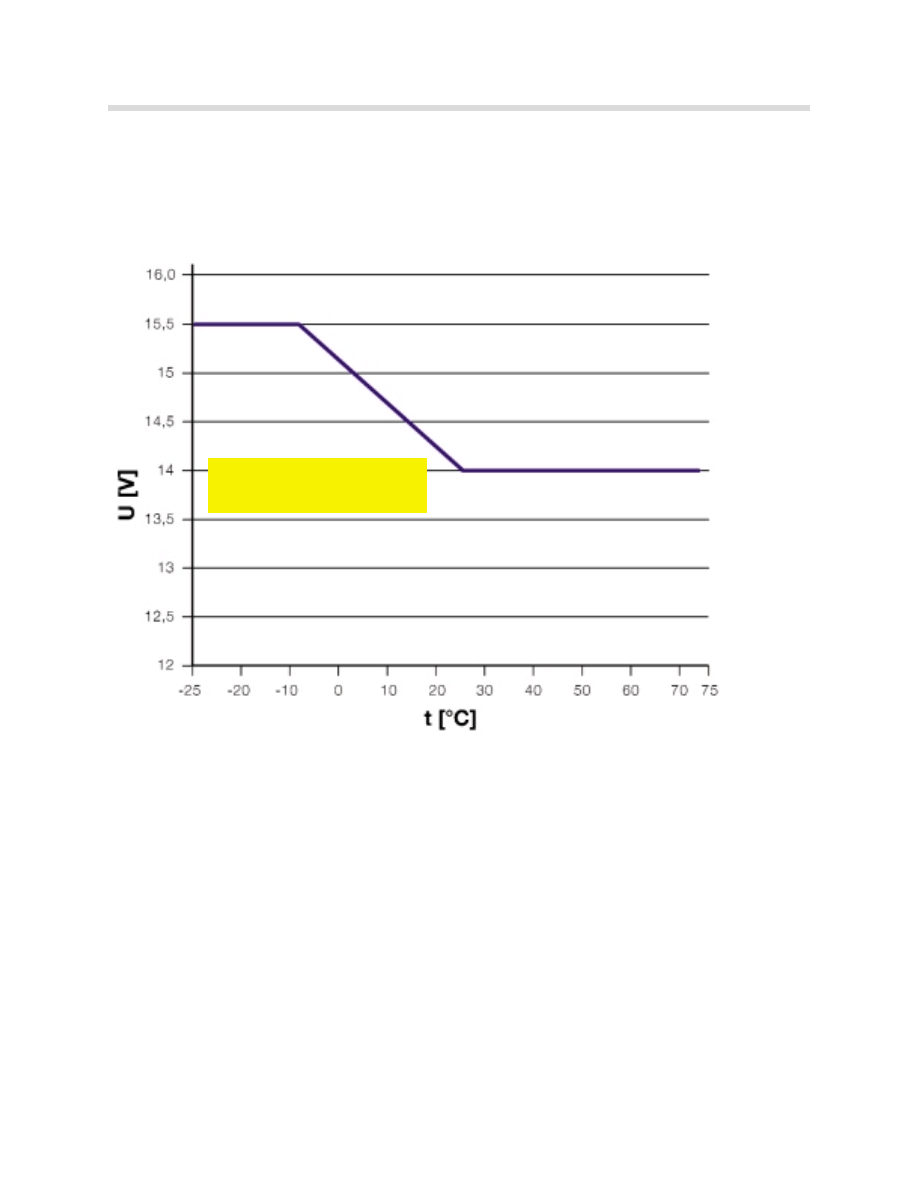
The battery voltage can fluctuate between 14.0 V and 15.5 V. The optimum charge volt-
age is set according to the charge level of the battery, the battery temperature and the sta-
tus of the external lights (higher charging voltage with lights off). The maximum setting is
16 V.
Battery Charge Level Detection
The Power Module knows what the charge level of the battery is at any time by calculating
the battery current when the vehicle is being driven and measuring the discharge current.
When the vehicle is not in use, the charge level is re-calculated and updated by measuring
the closed circuit battery voltage. If the vehicle battery is replaced it must be registered with
the Power Module so that the stored values can be deleted and a new calculation started.
This operation is described in “Service Functions”.
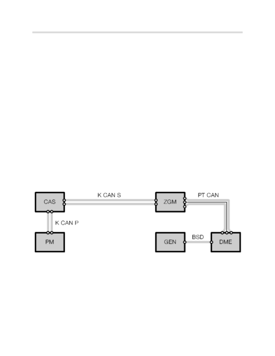
Temperature-Dependent Battery Charging Voltage
By using a charging characteristic map stored in the PM, the charge voltage of the gener-
ator is adjusted according to the battery temperature. The diagram below shows the com-
munication path necessary for the Power Module to inform the generator to increase or
decrease charge voltage output.
The Power Module detects the temperature of the battery and places the instruction
"Increase charge voltage" on the K-CAN Periphery. The Car Access System (CAS) pass-
es the message on to the K-CAN System bus.
The Central Gateway Module (ZGM) receives the message. Performing its function as a
"gateway control unit", it passes the message on to the PT-CAN.
The DME (ECM) module receives the request to increase the charge voltage over the PT-
CAN.
KT-8333
16
Power Module
The generator then receives the request to increase the charge voltage via the BSD lead
(bit serial data interface). The electronic evaluation unit in the generator then adjusts the
charge voltage accordingly.
If the temp. sensor is detected as defective then the charging voltage will be fixed at 14.3V.
Increasing Idle Speed to Improve Battery Charging
In order to drain as little energy as possible from the battery during freezing weather (below
34
o
F) the idling speed may be increased.
This ensures that the battery charge level is kept high. If the charge level falls below the
calculated minimum level for starting, the idling speed is increased to 750 rpm.
The calculation of the minimum level for starting takes account of the temperature and the
condition/age of the battery.
The temperature dependent
charge rate is illustrated by
this graph.
KT-8367

17
Power Module
Load-Circuit Peak Reduction
If battery discharge is detected while the engine is running (despite increased idling speed),
the power supply to electrical consumer circuits are gradually reduced or completely shut
off according to a table of priorities. The consumer systems concerned are divided into two
groups: Priority group A and Priority group B.
Priority group A
Priority group B
•
Rear window heater
• IHKA fan (except during defrosting)
• Headlight washing
• Rear IHKA fan (only for E66)
•
All seat heaters
•
Active seat
•
Seat ventilation
•
Steering wheel heater
•
Mirror heater
•
Windshield wiper blade heating
•
Wet arm (washer hose in wiper arm) heating
Priority A systems are dependent on battery SoC (State of Charge) and generator output
during the operation of the consumer.
Priority B systems are only dependent on the battery SoC.
The Power Module also sends out a telegram indicating the status of the Load-circuit peak
reduction function. The priority level of the message is classified by a number 0 through 6.
•
0 = Normal operation without peak reduction (KL 15 “ON”)
•
1 = Terminal R “ON” without peak reduction OR generator defect or under-voltage
acknowledged.
•
4 = Corresponds to maximum peak reduction.
•
5 = Corresponds to medium peak reduction.
•
6 = Corresponds to minimum peak reduction.
The computation by the Power Module to determine which priority level is necessary is
based on the battery SoC. Example: the threshold for priority level 6 is a 65% SoC.
Current vehicle priority levels can be displayed in the Diagnosis Program.

18
Power Module
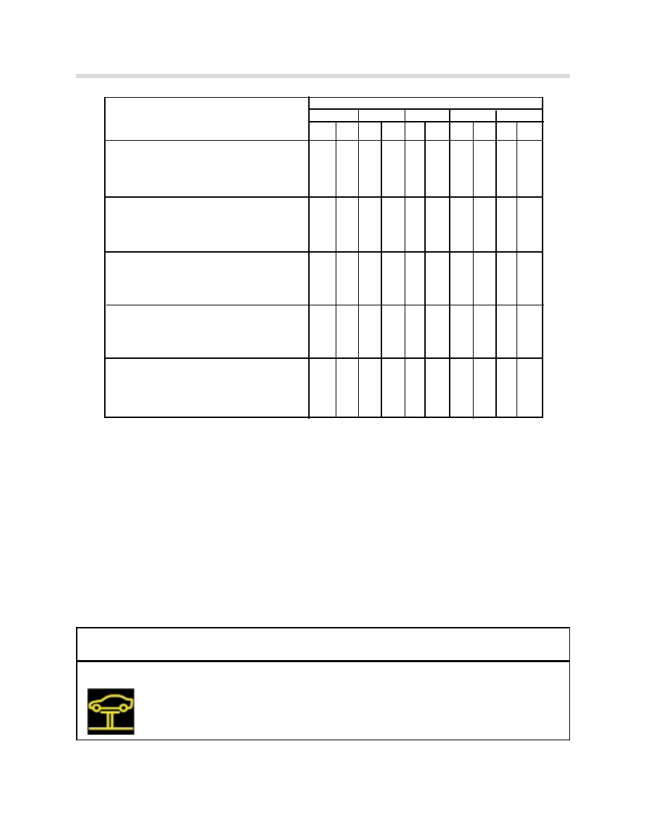
Priority Table for Load-Circuit Peak Reduction and Shut-Down Modes
Legend
•
X = Permitted operation at the priority level concerned
•
PM bus telegram priority A devices = Control peak reduction-priority
•
PM bus telegram priority B devices = Control peak reduction-comfort
•
Priority level:
0= Normal operation without peak reduction (KL 15 “ON”)
1= Terminal R “ON”, generator defect or under voltage acknowledged.
4= Corresponds to max. peak reduction.
5= Corresponds to medium peak reduction
6= Corresponds to minimum peak reduction
Priority Level
Consumer circuit
0 1 4 5 6
A B A
B
A B A B A
B
Rear window defogger
0ff
X X X X X
Intermittent operation
X X X
On X
Seat Heaters
Switched off
X
X
X
X
X
Temp. level 1
X
X X X
Temp. level 2
X
X
X
Temp. level 3
X
Max. rated output
X X
Half rated output
X X X X
Heater Fan (except during defrost)
Speed 0
X
X
Speed 1
X
X
X X
Speed 2
X
X X X
Speed 3
X X X
Steering wheel Heater
Level 0
X
X X X X
Level 1(clocked mode)
X
X X
Level 2 (fast heat up)
X
X
Mirror Heater
Off
X X X X X
On
X
19
Power Module
Shut-Down of Consumer Circuits in the Event of Low Voltage
If the battery voltage drops below 10.5 V (for 5 seconds) due to high load levels, the Power
Module sends out an instruction to increase the idling speed and to activate prioritized
shut-down of electrical consumer circuits.
At the same time, the power outputs of the Power Module (interior lighting, consumer iso-
lation circuit in roof/body zone) are switched off.
The following Check Control message appears:
Priority Level
Consumer circuit
0 1 4 5 6
A B A
B
A B A B A
B
Windshield heater ( wiper park pos.)
0ff
X X X X X
On X
Wet arm heater
Off
X
X
X
X
X
On
X
Headlight washer system
Off
X
X X X X
On
X
Active Seat
Off
X
X
X X X
On
X
X
Seat Ventilation
Off
X X X X X
On
X
X
X
Check Control Message
Message displayed in
Cause
displayed in KOMBI
Control Display
Power Module!
Power Module in emergency
Power Module
Drive moderately
operating mode. Electrical
conducting emergency
power supply limited. Please
shut-down mode.
contact the nearest BMW center.

20
Power Module
16 Minute Shut-Down of Consumer Circuits (Sleep mode)
To prevent battery discharge by consumer items mistakingly left on, the interior lighting cir-
cuit (IB) and consumer circuits-roof zone (VA-D) are shut off 16 minutes after terminal R is
switched off.
Shut-Down of Auxiliary Consumers
Auxiliary consumer circuits are items such as the CD, DWA, LM, EGS and IHKA (rest func-
tion).
In order to ensure that the car is capable of starting, the charge level (SoC-State of Charge)
of the battery is monitored when the vehicle is at rest.
The minimum battery SoC required to ensure that the car can be started again is a
calculated value. The calculation takes into account the:
•
Battery temperature measured over last few days
•
Engine type
•
Capacity of the battery fitted (110Ah for the 745i).
The SoC calculation is displayed as a percentage of battery capacity ( A fully charged bat-
tery is considered 80%).
If the charge level of the battery gets close to that calculated minimum level as a result of
the operation of an auxiliary consumer unit, the Power Module instructs that circuit to
switch off.
Two modes of operation are distinguished when shutting down auxiliary consumer circuits:
•
Auxiliary consumer with terminal R on.
•
Auxiliary consumer with terminal 0 (ignition off).
21
Power Module
Auxiliary Consumers and Terminal R
When terminal 15 changes to terminal R, the message Priority level 1 is broadcast.
Reduction of power consumption if necessary is then controlled on the basis of the table
on page 18 and 19.
The charge level of the battery is calculated. If it is still below the minimum level for start-
ing the car, the following Check Control message appears:
If the charge level does not improve, after 5 minutes the PM issues the "Shutdown
counter" message (shut-down message is to inform modules to store any information prior
to power being switched off). After a further 90 seconds, the vehicle's electrical system is
shut down.
This is on condition that no safety related consumers are switched on.
If safety related consumers are on (e.g. hazard lights), the battery is not disconnected from
the electrical system when the minimum battery SoC for starting the car is reached. The
battery is allowed to fully discharge.
Auxiliary Consumers and Terminal 0
If the driver switches on an auxiliary consumer it logs itself on by issuing the message
"Auxiliary consumer power management". By doing so, it triggers the PM to precisely cal-
culate the battery charge level.
Following a successful log-on, the auxiliary consumer goes into operation and the charge
level of the battery is monitored.
If the charge level falls below the minimum level for starting the car, the following Check
Control message appears:
Check Control Message
Message displayed in
Cause
displayed in KOMBI
Control Display
Recharge Battery!
Recharge battery!
Battery discharged
Battery heavily discharged.
Charge by driving for longer period
or by using external charger.
Battery will be disconnected soon.
Check Control Message
Message displayed in
Cause
displayed in KOMBI
Control Display
Recharge Battery!
Recharge battery!
Battery discharged
Battery heavily discharged.
Charge by driving for longer period
or by using external charger.
Battery will be disconnected soon.
22
Power Module
Five minutes later, if no legally required consumers are switched on, the PM automatically
switches to "closed-circuit current monitoring" mode.
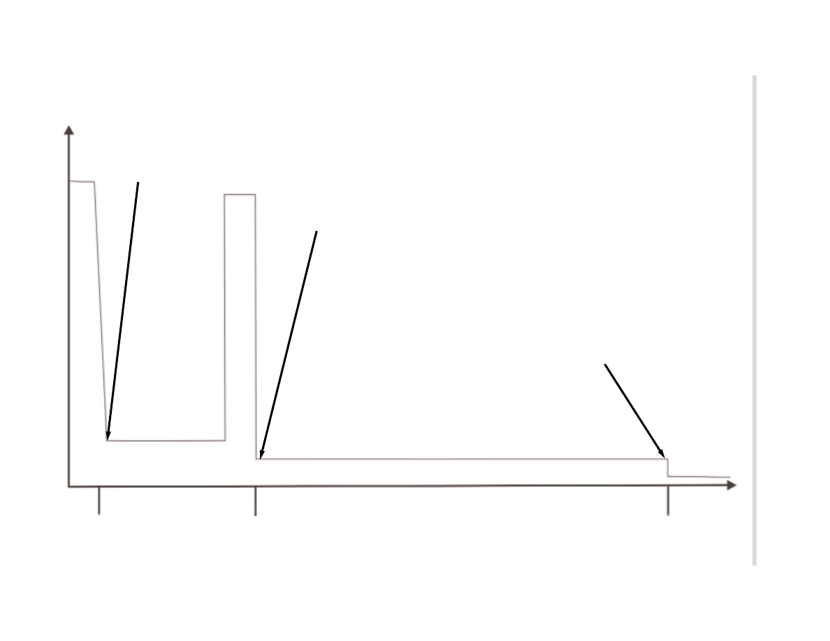
Closed-Circuit Current Monitoring (Standby Current)
When terminal 0 is active, the PM switches over to closed-circuit current monitoring after
60 minutes. If an operation is performed on the car before 60 minutes has elapsed (e.g.
central locking, trunk opened), the timer starts from the beginning again.
Once that period has ended, the closed-circuit current should not exceed 80 mA. If the
closed-circuit current exceeds 80 mA, after 5 minutes the PM issues the "Shutdown
counter" message. After a further 90 seconds, the vehicle's electrical system is shut down
for 5 seconds.
If the quiescent current still exceeds 80 mA when the system is switched on again, the
sequence described above is repeated. If the quiescent current is then still over 80 mA,
the system is permanently shut down via the electronic battery master switch.
The fault is recorded in the Power Module's fault memory (with details of environmental
conditions and cause).
When the signal “15w” from the CAS is detected, the electronic battery master switch is
closed and the following Check Control message is displayed:
Closed-circuit current monitoring is automatically cancelled by a message from the LM that
the hazard warning lights are active.
When terminal R is switched off, current monitoring is also immediately activated. Normal
current load on the vehicle drops in stages according to the vehicle programming for sleep
mode (see the chart on the following page).
If the monitored current is more than 120 amps (even as a random spike) , the interior light-
ing, roof area consumers and body zone consumer circuits are immediately switched off.
Check Control Message
Message displayed in
Cause
displayed in KOMBI
Control Display
High standby current!
High standby current!
Excessive closed-
Vehicle electrical accessories
circuit current draw
are drawing excessive passive-state
current. Battery has been disconnected
Please contact your BMW center.
23
Power
Module
800mA
200mA
25 seconds
16 minutes
1 hour
50mA
Bus communication ended: Vehicle in sleep mode! Indicator: CAS lighting out
Sleep mode: VA-D (consumer circuit-roof) switched off
Indicator: BZM lighting (seat switches) out, trunk light out.
Sleep mode: VA-K (consumer circuit-body)
switched off.
• Cigarette lighter relay
• Telephone
• Power Module
Closed-Circuit Consumer Monitoring and Vehicle Sleep
Mode
12 A
Bus
T
elegram:
“Sleep
counter”
24
Power Module
Storage Mode
By switching “OFF” the battery switch, the Power
Module goes into Storage Mode 30 minutes after
terminal R switches off.
Before disconnecting, the PM sends out the "Shutdown" signal. After a further 90 seconds
the shut down is completed. If the ignition switch is turned to terminal R “On”, a Check
Control message is issued which informs the driver that the vehicle is in Storage Mode.
The following CC message appears:
When the signal “15w” or change-over of the battery switch to "closed-circuit current mon-
itoring" is detected, the electronic battery master switch is closed.
The car can still be started and driven in storage mode. All systems remain functional.
The CC message remains active.
When "Terminal R Off" is active, disconnection is carried out after 30 minutes (as explained
above).
IIff n
no
o ffu
un
nc
cttiio
on
n o
off a
an
ny
y k
kiin
nd
d iis
s a
ac
cttiiv
va
atte
ed
d o
ov
ve
err a
a p
pe
erriio
od
d o
off 3
3 w
we
ee
ek
ks
s,, tth
he
e b
ba
atttte
erry
y iis
s d
diis
sc
co
on
nn
ne
ec
ctte
ed
d
c
co
om
mp
plle
ette
elly
y ffrro
om
m tth
he
e v
ve
eh
hiic
clle
e''s
s e
elle
ec
cttrriic
ca
all s
sy
ys
stte
em
m.. T
Th
hiis
s p
prre
ev
ve
en
ntts
s b
ba
atttte
erry
y d
diis
sc
ch
ha
arrg
ge
e.. T
Th
hiis
s ffu
un
nc
c--
ttiio
on
n iis
s iin
nd
de
ep
pe
en
nd
da
an
ntt o
off tth
he
e p
po
os
siittiio
on
n o
off tth
he
e b
ba
atttte
erry
y s
sw
wiittc
ch
h..
Electronic Fuse
If a short circuit current of over 250 A is detected, the battery master switch is opened.
When the wake-up signal “15w” from the CAS is detected, then an attempt is made to
close the battery master switch again.
This procedure is repeated continually until the short circuit has been eliminated.
OFF
KT-8288
Check Control Message
Message displayed in
Cause
displayed in KOMBI
Control Display
Battery switch OFF !
Battery switch OFF!
Battery switch left in
Re-set battery switch in luggage
OFF position.
compartment to ON, refer to
owners manual.

25
Power Module
Central Battery Voltage Notification
The Power Module continuously measures the battery voltage. This information is made
available to all other control units via the bus link. This can be used, for example, to enable
continuous running of the sliding/tilting sunroof regardless of battery voltage.
Central battery voltage notification eliminates the need for individual measurement of bat-
tery voltage by each control unit.
Rear Window Heater (HHS)
The electronic rear window heater output stage of the PM is activated by a "HHS On" (K-
CAN-S via CAS via K-CAN -P) message from the IHKA control unit. Control is directly by
the final stage.
Interior Lighting
The interior lighting is subdivided between three outputs (groups):
•
IB (interior lighting)
•
VA-K (consumer isolation circuit, body zone)
•
VA-D (consumer isolation circuit, roof zone)
The interior lighting is controlled by the PM, the outputs are 12V stabilized-voltage.
VA-K and VA-D are switched on/off according to the status of the relevant switches.
Trunk Lid and Fuel Filler Flap Control
The Power Module controls the following trunk-lid related functions of the body zone elec-
tronics:
•
Trunk lock actuator
•
Trunk lid automatic soft close motor (SCA)
•
Fuel filler flap lock actuator
The necessary software, such as on times and repeat lockouts is integrated in the PM. For
more details, refer to the chapter: Central Body Electronics.
The PM monitors the trunk lid for the DWA system via the trunk lock actuator (ZV) contact
switch.

26
Power Module
Data Memory
The data memory stores data relevant to the vehicle. That information provides a status
read-out of the battery load and life. It can be accessed by way of the diagnosis function.
The data memory will be used in future to obtain a load profile of the battery in normal oper-
ation that will be analyzed for the purposes of "condition based servicing."
Emergency-Mode Functions
Battery Temperature Sensor
In the event of a defective sensor, a short circuit or an implausible value, the substitute value
of 20 ºC is assumed. This corresponds to a fixed charge voltage of 14.3 V at the battery.
Battery capacity (SoC) is calculated using the substitute value.
Battery Switch
If a fault is detected in the battery switch, the Power Module switches to Storage mode as
if the switch were in the “OFF” position.
Terminal 15w
Shut-down of the PM in the absence of terminal 15w is prevented by the following dupli-
cated signals:
•
Terminal 15 (from CAS via bus link)
•
Road speed > 2 km/h (from DSC via bus link)
•
System voltage > 13.2 V (PM central battery voltage notification)
Bus Communication
If bus communication is not possible, all information is "frozen."
27
Power Module
Check Control Messages
The following are all of the possible Power Module relevant messages:
Check Control Message
Message displayed in
Cause
displayed in KOMBI
Control Display
Battery Switch OFF!
Battery switch OFF!
Battery switch left in
Re-set battery switch in luggage
OFF position.
compartment to ON, refer to
owners manual.
High standby current!
High standby current!
Excessive closed-
Vehicle electrical accessories
circuit current draw.
are drawing excessive passive-state
current. Battery has been disconnected
Please contact your BMW center.
Recharge Battery!
Recharge battery!
Battery discharged
Battery heavily discharged.
Charge by driving for longer period
or by using external charger.
Battery will be disconnected soon.
Power Module!
Power module in emergency !
Power module in
drive moderately
operating mode. Electrical
emergency mode
power supply limited. Please
contact the nearest BMW center.
Power Module failure!
Power module failure!
Power module alive
Automatic monitoring of
signal missing over
battery charge level failure.
bus line.
Please contact the nearest BMW
center.
28
Power Module
Workshop Hints
Battery Charging
As with previous models, a battery charger can be connected in the engine compartment
to the battery junction point or directly to the battery in the trunk. The PM detects an exter-
nal battery charger if the battery voltage is above 13.2 V for 1 hour without the engine run-
ning.
Following detection of external battery charging, a battery charge level of 80% is reported
even if the charge level is higher or lower than that figure.
Cigarette Lighter Battery Charging Function
A trickle charger can also be connected to the cigarette lighter. However, the cigarette
lighter is supplied by the body-zone consumer isolation circuit (VA-K) via a relay.
If the "terminal R Off" signal is present for more than 60 minutes, that relay will be switched
off by the consumer shutdown function. That would mean that a charger connected to the
cigarette lighter would be disconnected from the battery.
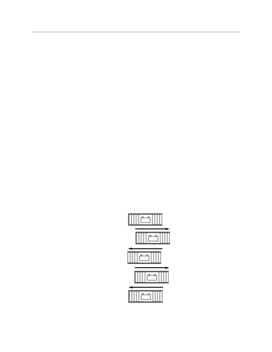
To prevent this, the consumer shut-down function can be deactivated. This is performed by
the following procedure:
Slide the battery switch off and on again twice within two seconds.
1. Switch ON (starting position)
2. Switch OFF
3. Switch ON
4. Switch OFF
5. Switch ON
The function is cancelled by: "terminal 15 On" , switching the battery switch from "OFF" to
"ON" or failure of the battery voltage to reach 12.6 V after 6 hours of charging.
ON
ON
ON
ON
ON
OFF
OFF
OFF
OFF
OFF

29
Power Module
Diagnosis
All inputs/outputs that are part of the Power Module can be diagnosed by Test Modules or
status checked by the Control Unit Functions of the Diagnosis Program. The outputs can
also be activated by Component Activation and the power consumption displayed.
The Diagnosis Program is based on the E46 concept.
All electronic fuses and the electronic battery master switch are monitored for short cir-
cuits/circuit breaks. In the event of a fault, an appropriate entry is made in the PM's
fault memory and, if appropriate, a check control message initiated.
Service Functions
Sleep Mode Activation
This function can be used to put the control units into sleep mode. The battery switch must
be set to “ON” when using this feature. The Test module will indicate whether the function
was successful or not.
Battery Replacement Registration ((M
Mu
us
stt b
be
e p
pe
errffo
orrm
me
ed
d a
an
ny
y ttiim
me
e a
a b
ba
atttte
erry
y iis
s rre
ep
plla
ac
ce
ed
d))**
This Service Function informs the PM that the battery has been replaced. It completes the
following operations:
•
The battery capacity is set to 80%.
•
The current odometer reading is stored.
The odometer readings at which the last seven battery replacements took place can be
read off from the Diagnosis Requests of Control Unit Functions.
•
The stored battery statistics (current, voltage, battery charge level) are deleted.
•
The stored temperature statistics are deleted.
Transport Mode Clearing
Vehicles that arrive at the BMW centers may have the Transport Mode cleared by using the
Test Module under the Service Functions menu. Different from the Storage Mode
described on page 24, certain consumers such as the radio, interior lights, and electric win-
dows (except drivers side) are permanently switched off.

30
Power Module
Review Questions
1. Name a feature of the Power Module that is responsible for ensuring that important
systems have power, even if a voltage loss while driving is detected. How can the
Power Module react to a loss in power?
2. What information does the Power Module use to calculate the optimum charge voltage?
3. Which control unit provides the 15w (wake-up) signal to the Power Module? What
would happen if the wire for the 15w input were damaged?
4. How would the driver of the vehicle know that the battery switch was in the OFF
position?
5. How is the Power Module informed that an external battery charger has been
connected?
6. What must be performed to the Power Module after replacing a battery?
7. Why is the Power Module responsible for controlling the trunk and filler flap lock
actuators?
Document Outline
- Main Menu
- E65 Introduction
- E66 Body
- E65 Bus Systems
- E65 Power Module
- E65 Car Access System
- E65 iDrive (Driving Area)
- E65 Instrument Cluster
- E65 iDrive (Comfort Area)
- E65 Audio System
- E65 Navigation System
- E65 Telephone
- E65 Speech Processing System
- E65 Intelligent Safety Integration System
- E65 Central Body Electronics
- E65 Remote Control Service
- E65 Automatic Trunk Lid Lift
- E65 Windshield Wiping & Washing
- E65 Seat, Mirror & Steering
- E65 Vehicle Lighting System
- E65 Anti-Theft Alarm System
- E65 Tire Pressure Control
- E65 Park Distance Control
- Active Cruise Control
- ACC Workbook
- E65/66 IHKA
- E66 Rear Air
- Diagnostic Equipment
Wyszukiwarka
Podobne podstrony:
02a E65 Power Module(1)
[EP 2003] 1381775 WIND TURBINE POWER MODULE MOUNTED ON THE TOWER FOUNDATION
Ambient Power Module
[EP 2003] 1381775 WIND TURBINE POWER MODULE MOUNTED ON THE TOWER FOUNDATION
04 BS Module 1 Section 4
Module 04 id 305941 Nieznany
04 1c PHASEO POWER SUPP AND TRA Nieznany (2)
Assertivness Module 04
04 BS Module 1 Section 4
CE Elementary module 04 web worksheet
04 Wind Turbine Power, Energy And Torque
Natural Power 530 03 980 Punto Evo PL 2ed 04 2010
04 cisco semestr 3 v31 module 4 exam
Tracy Falbe The Rys Chronicles 04 The Borderlands Of Power
więcej podobnych podstron