
Initial Print Date: 12/04
Table of Contents
Subject
Page
Power Module and Voltage Supply Components . . . . . . . . . . . . . . . .5
Location and Construction of the Power Module . . . . . . . . . . . . . . . . . . .5
Power Supply Circuit . . . . . . . . . . . . . . . . . . . . . . . . . . . . . . . . . . . . . . . . . . . .6
Positive Battery Cable . . . . . . . . . . . . . . . . . . . . . . . . . . . . . . . . . . . . . . . . . . .7
Battery . . . . . . . . . . . . . . . . . . . . . . . . . . . . . . . . . . . . . . . . . . . . . . . . . . . . . . . .8
Service Instructions for AGM Batteries . . . . . . . . . . . . . . . . . . . . . . . . . . .9
Charging . . . . . . . . . . . . . . . . . . . . . . . . . . . . . . . . . . . . . . . . . . . . . . . . . . . .9
Installation Location . . . . . . . . . . . . . . . . . . . . . . . . . . . . . . . . . . . . . . . . .10
Do Not Open . . . . . . . . . . . . . . . . . . . . . . . . . . . . . . . . . . . . . . . . . . . . . . .10
Battery Replacement . . . . . . . . . . . . . . . . . . . . . . . . . . . . . . . . . . . . . . . .10
Fuses . . . . . . . . . . . . . . . . . . . . . . . . . . . . . . . . . . . . . . . . . . . . . . . . . . . . . . . .10
Luggage Compartment Fuses . . . . . . . . . . . . . . . . . . . . . . . . . . . . . . . . . .11
Interior Fuses . . . . . . . . . . . . . . . . . . . . . . . . . . . . . . . . . . . . . . . . . . . . . . . . .11
Electronic Battery Master Switch . . . . . . . . . . . . . . . . . . . . . . . . . . . . . . . .12
High Current Terminals (RADSOK) . . . . . . . . . . . . . . . . . . . . . . . . . . . . . .12
Power Module Inputs . . . . . . . . . . . . . . . . . . . . . . . . . . . . . . . . . . . . . . . . . .13
Outputs Connected to Electronic Battery Master Switch . . . . . . . . . . .14
Outputs not Connected to Electronic Battery Master Switch . . . . . . .14
Fuses . . . . . . . . . . . . . . . . . . . . . . . . . . . . . . . . . . . . . . . . . . . . . . . . . . . . . . . .15
E65 Power Module
Revision Date:

Subject
Page
Power Module Functions . . . . . . . . . . . . . . . . . . . . . . . . . . . . . . . . . . . . .16
Battery Charge Level Detection . . . . . . . . . . . . . . . . . . . . . . . . . . . . . . .16
Temperature-Dependent Battery Charging Voltage . . . . . . . . . . . . .16
Increasing Idle Speed to Improve Battery Charging . . . . . . . . . . . . .17
Load-Circuit Peak Reduction . . . . . . . . . . . . . . . . . . . . . . . . . . . . . . . . . . . .18
Priority Table for Load-Circuit Peak Reduction and
Shut-Down Modes . . . . . . . . . . . . . . . . . . . . . . . . . . . . . . . . . . . . . . . . . . . .19
Shut-Down of Consumer Circuits in the Event of Low Voltage . . . . . .20
16 Minute Shut-Down of Consumer Circuits (Sleep mode) . . . . . . . . .21
Shut-Down of Auxiliary Consumers . . . . . . . . . . . . . . . . . . . . . . . . . . . . .21
Closed-Circuit Current Monitoring (Standby Current) . . . . . . . . . . . . . .23
Closed Circuit Consumer Monitoring and Vehicle Sleep Mode . .24
Storage Mode . . . . . . . . . . . . . . . . . . . . . . . . . . . . . . . . . . . . . . . . . . . . . . . .25
Electronic Fuse . . . . . . . . . . . . . . . . . . . . . . . . . . . . . . . . . . . . . . . . . . . . . . .25
Central Battery Voltage Notification . . . . . . . . . . . . . . . . . . . . . . . . . . . . . .26
Rear Window Heater (HHS) . . . . . . . . . . . . . . . . . . . . . . . . . . . . . . . . . . . . .26
Interior Lighting . . . . . . . . . . . . . . . . . . . . . . . . . . . . . . . . . . . . . . . . . . . . . . .26
Trunk Lid and Fuel Filler Flap Control . . . . . . . . . . . . . . . . . . . . . . . . . . . .26
Data Memory . . . . . . . . . . . . . . . . . . . . . . . . . . . . . . . . . . . . . . . . . . . . . . . . .27
Emergency-Mode Functions . . . . . . . . . . . . . . . . . . . . . . . . . . . . . . . . . . .27
Summary of Check Control Messages for Power Module . . . . . . . . . .28
Battery Charging . . . . . . . . . . . . . . . . . . . . . . . . . . . . . . . . . . . . . . . . . . . . . .29
Cigarette Lighter Battery Charging Function . . . . . . . . . . . . . . . . . . . . . .29
Diagnosis . . . . . . . . . . . . . . . . . . . . . . . . . . . . . . . . . . . . . . . . . . . . . . . . . . . . .30
Service Functions . . . . . . . . . . . . . . . . . . . . . . . . . . . . . . . . . . . . . . . . . . . . .30

3
E65 Power Module
E65 Power Module
Model: E65, E66
Production: All
After completion of this module you will be able to:
• Identify and locate the power module and related components
• Understand power module functions
• Perform closed-circuit current diagnosis
• Perform service related functions on the power module
4
E65 Power Module
Power Module
The Power Module (PM) is one of the innovative new developments on the E65. The job
of the Power Module is to ensure that the battery charge level is maintained when the
engine is running and when the vehicle is at rest. The Power Module is also responsible
for maintaining the power supply (in the event of faults in the electrical system) to impor-
tant vehicle systems by disconnecting lower priority circuits.
The PM functions include:
• Optimum charging
• Load-circuit peak reduction
• Shut-down of auxiliary consumer circuits in the event of low voltage
• Closed circuit current monitoring
• Distribution mode
• Automatic electrical system isolation
• Load cutout
• Electronic fuses
• Central battery voltage notification
• Rear window defogger output
• Interior lighting control
• Trunk lid and fuel filler flap control
• Data memory storage
• Emergency-mode functions
• Check Control messages
• Diagnosis
5
E65 Power Module
Power Module and Voltage Supply Components
The power supply components in the E65 include:
• The power supply circuit
• Vehicle Fuses
• The power module
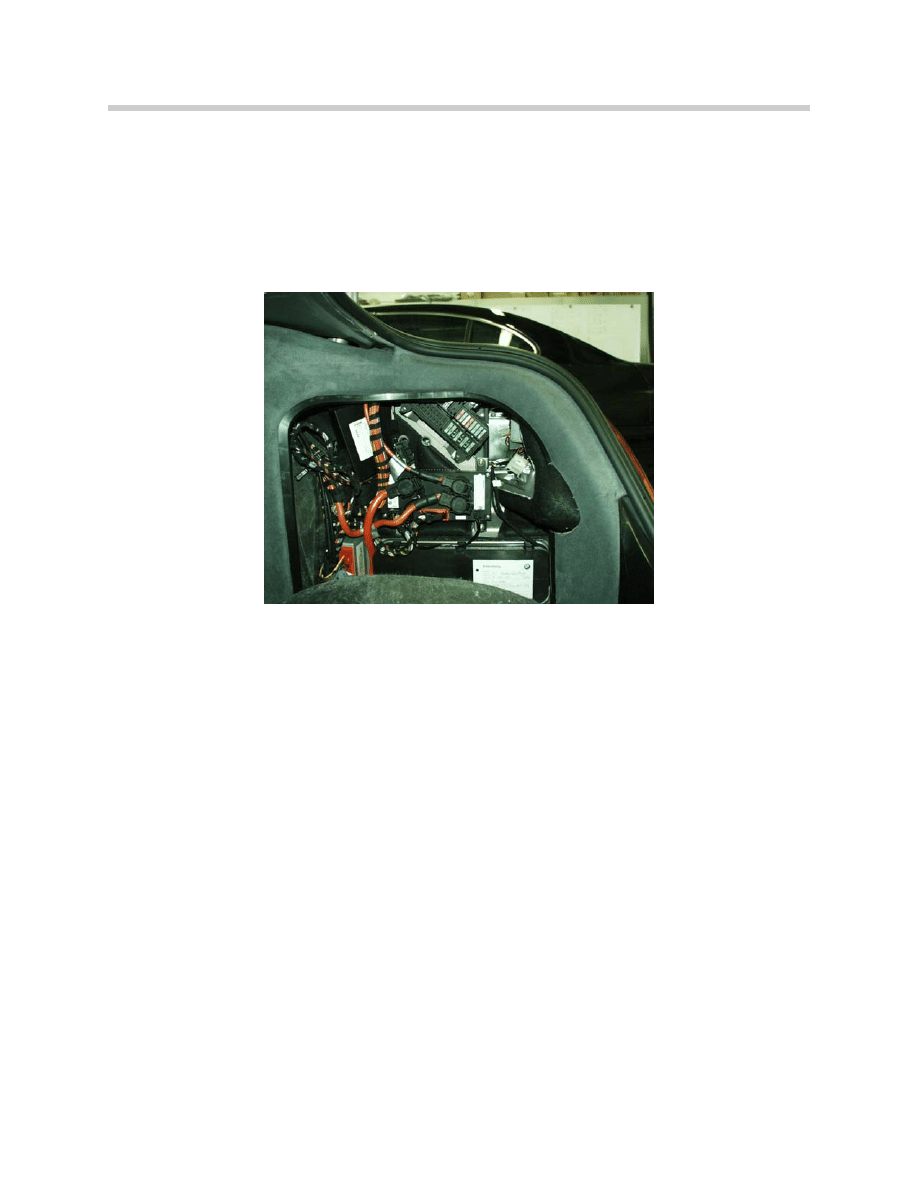
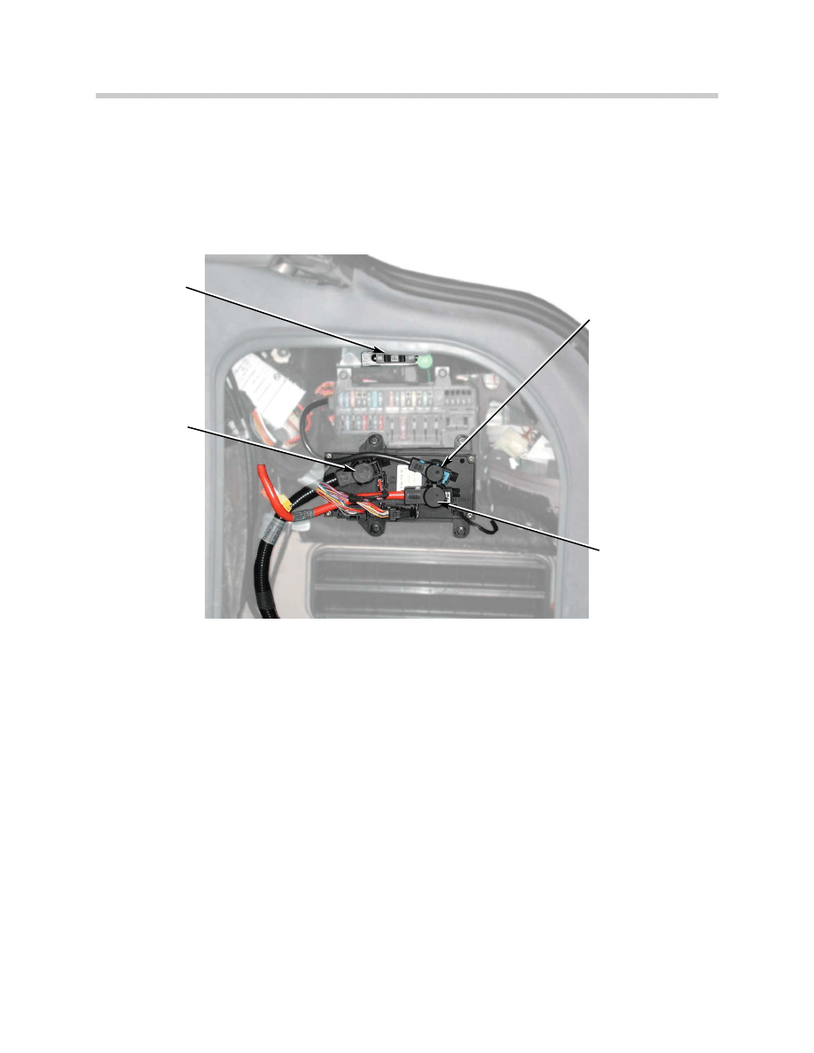
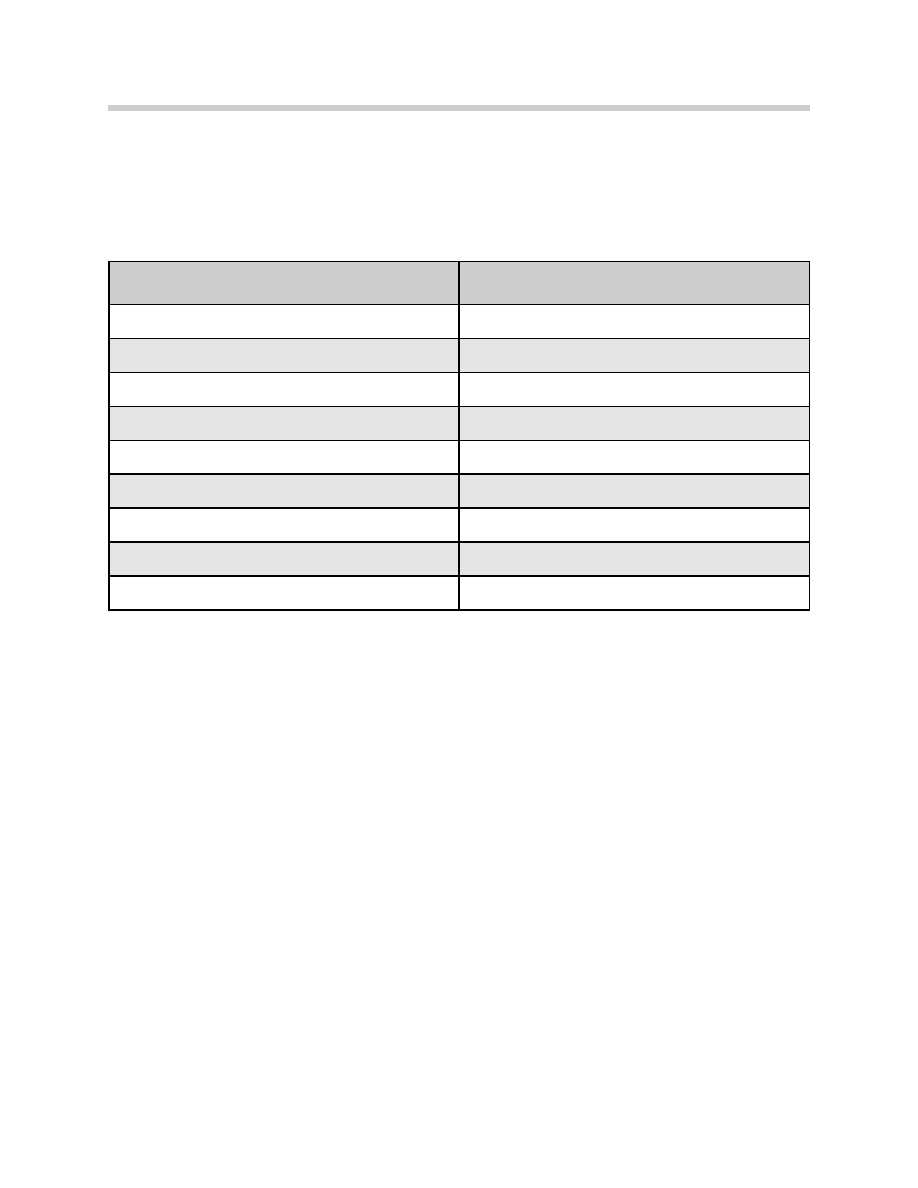
Location and Construction of the Power
Module
The power module is located on the right hand
side of the luggage compartment behind the
trim panel (above the battery).
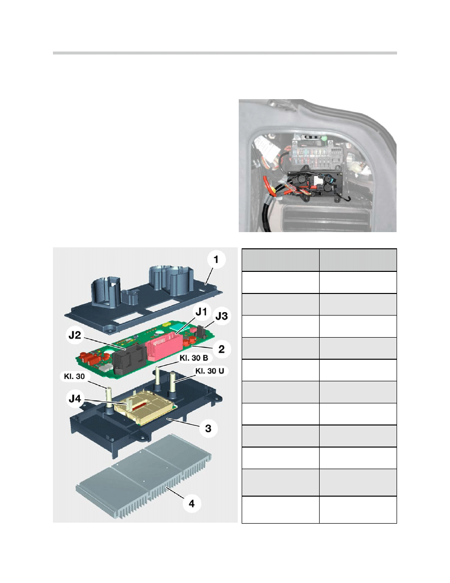
Index
Explanation
1
Cover Plate
2
Electronics
3
Baseplate
4
Heat Sink
J1
Connector
J2
Connector
J3
J4
Battery Master Switch
KL30
Continuous B+
KL30B
Glove compartment fuse
box power supply from
master switch
KL30U
Luggage compartment
fuse box power supply
from master switch
6
E65 Power Module
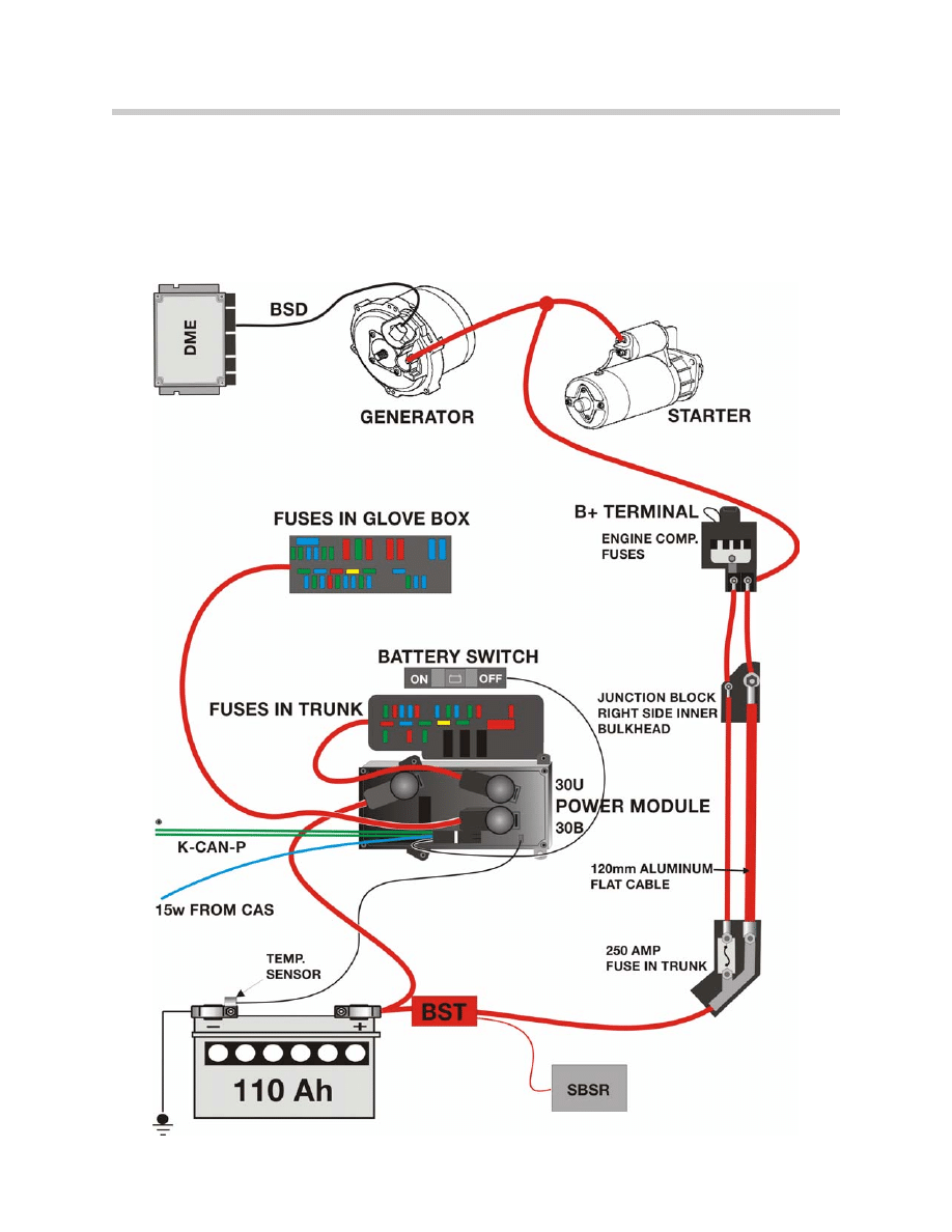
Power Supply Circuit
The power supply for the general electrical system is controlled by the power module.
The high amperage fuses located in the engine compartment, the generator and the
starter motor are connected directly to the battery and are not supplied by the Power
Module.
7
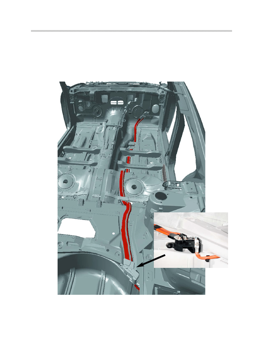
E65 Power Module
Positive Battery Cable
An aluminum battery cable in the E65 is used for the first time by a BMW automobile.
The cable is flat (120mm
2
) and runs along the vehicle interior from a junction box ahead
of the spare tire well to the interior side of the front bulkhead. A smaller copper cable
runs parallel to it in the vehicle interior. That smaller cable is supplied via a 250 amp fuse
located inside the same junction box that feeds the aluminum cable.
Junction point with 250 amp fuse
8
E65 Power Module
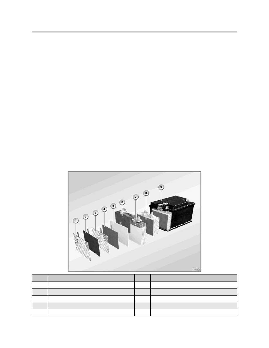
Battery
From the start of production, the E65 was fitted with a single maintenance free battery
(12V/110AH). The battery is located in the right hand side of the trunk below the vehicle
jack.
As of September 2002 production, the E65/E66 was fitted with new battery technology.
The AGM batteries are now standard equipment. (AGM stands for Absorbent Glass Mat)
The AGM battery variant is a 90 Ah unit and can be identified by the black plastic casing
as opposed to the white casing on conventional lead-calcium batteries.
AGM batteries are more expensive to produce, however this extra cost is offset by the fol-
lowing benefits:
• Greatly enhanced service life
• Improved starting reliability at low temperatures
• Reliable starting of engine with high starting current requirements
• 100% maintenance free
• Low environmental risk in the event of an accident
In contrast to conventional lead-calcium batteries, the sulphuric acid in an AGM battery is
not held freely in the battery housing.
Index
Explanation
Index
Explanation
1
Positive grill with silver alloy
6
Set of positive plates
2
Positive plate
7
Set of negative plates
3
Negative grill
8
Block of plates
4
Negative plate
9
Block box with base strips
5
Separator made of glass fiber fleece

9
E65 Power Module
The sulphuric acid is instead entirely bound into the mats of the glass-fibre fleece. For
this reason, no acid can escape if the battery housing is damaged. In addition, the AGM
battery is a sealed, airtight unit. This is possible because the gasses are converted back
into water by the permeability of the separators.
Construction
AGM batteries differ from conventional lead-calcium batteries in the following points:
• Larger plates which allow a power density some 25% greater.
• Glass-fiber-fleece separators which enables a cycle consistency up to 3 times
greater to be achieved which improves cold-starting ability, current consumption
and service life.
• Airtight housing with pressure relief valve
• The inspection plugs are sealed and cannot be opened.
• Acid bound in glass-fiber fleece:
How it Works
AGM batteries differ from conventional lead-calcium batteries in their environmental com-
patibility and their retention of gases during charging.When a vehicle battery is charged,
the electrolysis process emits the gases oxygen and hydrogen.
In a conventional lead-calcium battery, these two gases are released into the atmosphere.
In an AGM battery, the two gases are converted back into water: The oxygen created at
the positive electrode during charging moves through the permeable glass-fiber fleece to
the negative electrode, where it reacts with the hydrogen ions that are brought in with the
electrolyte, to create water (oxygen cycle). In this manner, the gases, and thus the elec-
trolyte, is not lost.
Only when the gas production is excessive, that is when too much pressure is generated
(20 to 200 mbar), does the pressure-relief valve open, thereby allowing gas to escape
while also preventing entry of atmospheric oxygen. Because the pressure in the battery is
regulated by a valve, the AGM battery is also known as the VRLA battery (valve-regulated
lead acid).
Service Instructions for AGM Batteries
When handling AGM batteries, certain special factors must be taken into consideration
with regard to battery renewal and installation location.
Charging
Do not charge AGM batteries with 14.8 volts!
Do not use rapid charging programs!
When charging batteries in the "stand alone" mode, the maximum charge voltage of 14.8
volts must not be exceeded. Even briefly charging an AGM battery with a charge voltage
of more than 14.8 volts (voltages usually used in rapid charge programs) will damage the
battery.
Warning!!!
10
E65 Power Module
Installation Location
Do not install AGM batteries in the engine compartment!
Because of large temperature variations, AGM batteries must not be installed in the
engine compartment. This would result in a significant reduction in the service life of the
battery.
Do Not Open
Do not open AGM batteries
On no account should AGM batteries be opened, as oxygen from the atmosphere would
cause the battery to lose its chemical balance and cause it to fail.
Battery Replacement
An AGM battery, when installed as original equipment, must always be replaced with an
AGM battery.
In special cases, where a customer's driving profile (e.g. short distance driving), results in
a discharged battery, the AGM battery is a recommended replacement. Note that
replacement batteries resulting from a customer's driving profile cannot be claimed under
warranty.
Fuses
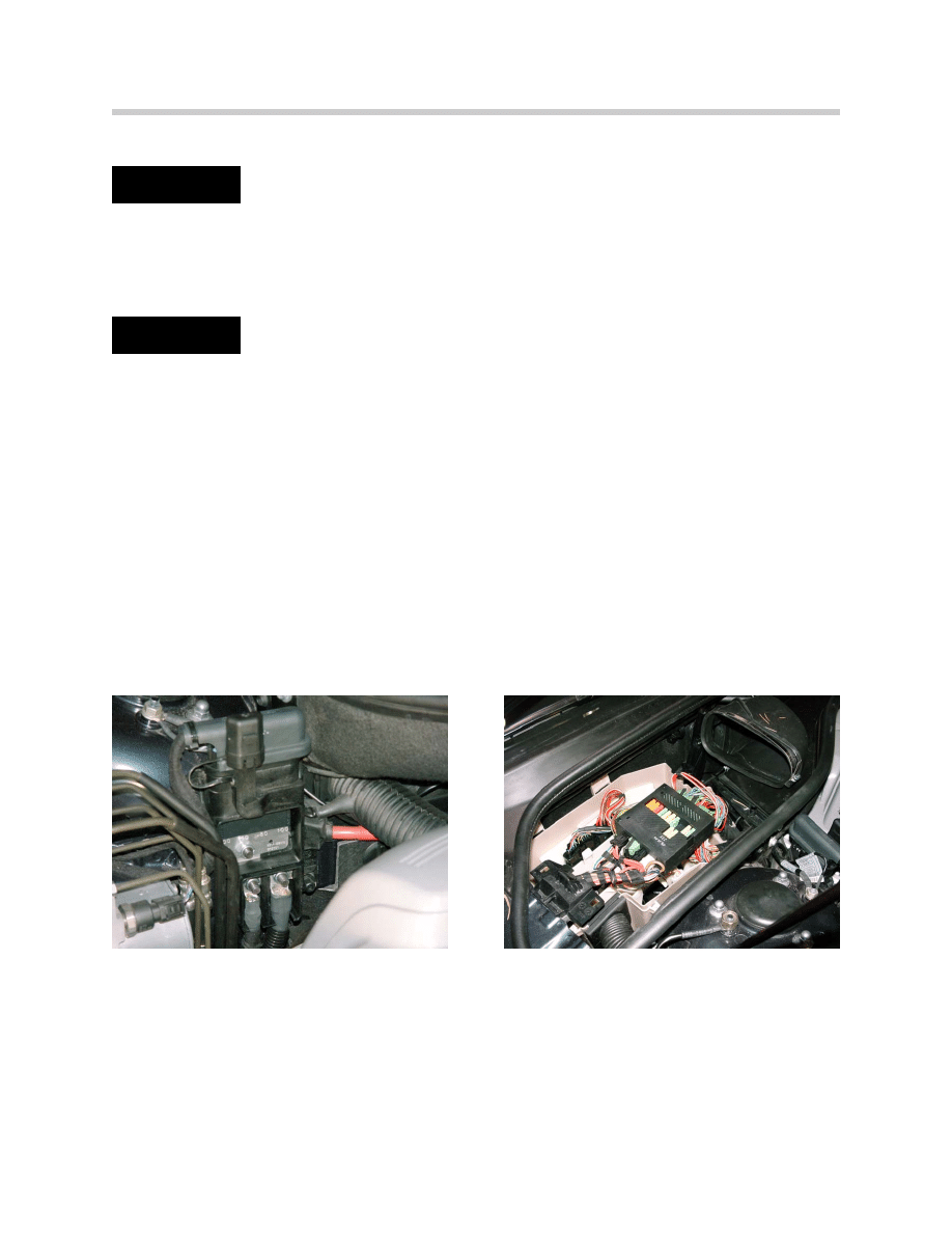
The locations of the fuses are as follows:
Engine Compartment
Next to jump-start connection point
• F101 100 A IVM (Engine/DME Supply)
• F102 50A Secondary Air Pump
• F103 80A Auxiliary Fan
• F104 100A IVM (Engine/DME Supply)
Note: Fuses 101-104 is a bus strip that is
replaced as a complete unit if one cir-
cuit is blown.
Right side of engine compartment
inside the Integrated Voltage Supply
Module (IVM).
Warning!!!
Warning!!!
11
E65 Power Module
Luggage Compartment Fuses
Interior Fuses
Apart from the fuses referred to above, certain control units have integrated electronic
fuses which protect components which are directly connected to the control unit.
Right side of luggage compartment -
fuses 51-84
Junction point with 120mm2 aluminum flat
cable , 250 Amp fusible link (F-200)
Glovebox - Fuses 1-44
12
E65 Power Module
Electronic Battery Master Switch
The electronic battery master switch is made up of 4 MOSFET output stages (S Bat) and
connects the input terminal 30 with the outputs KL30U and KL30B on the Power
Module.
The following functions are controlled by means of the power module according to the
position of the battery switch:
• Storage mode
• Closed circuit current monitoring
• Electronic fuses
• Automatic electrical system isolation
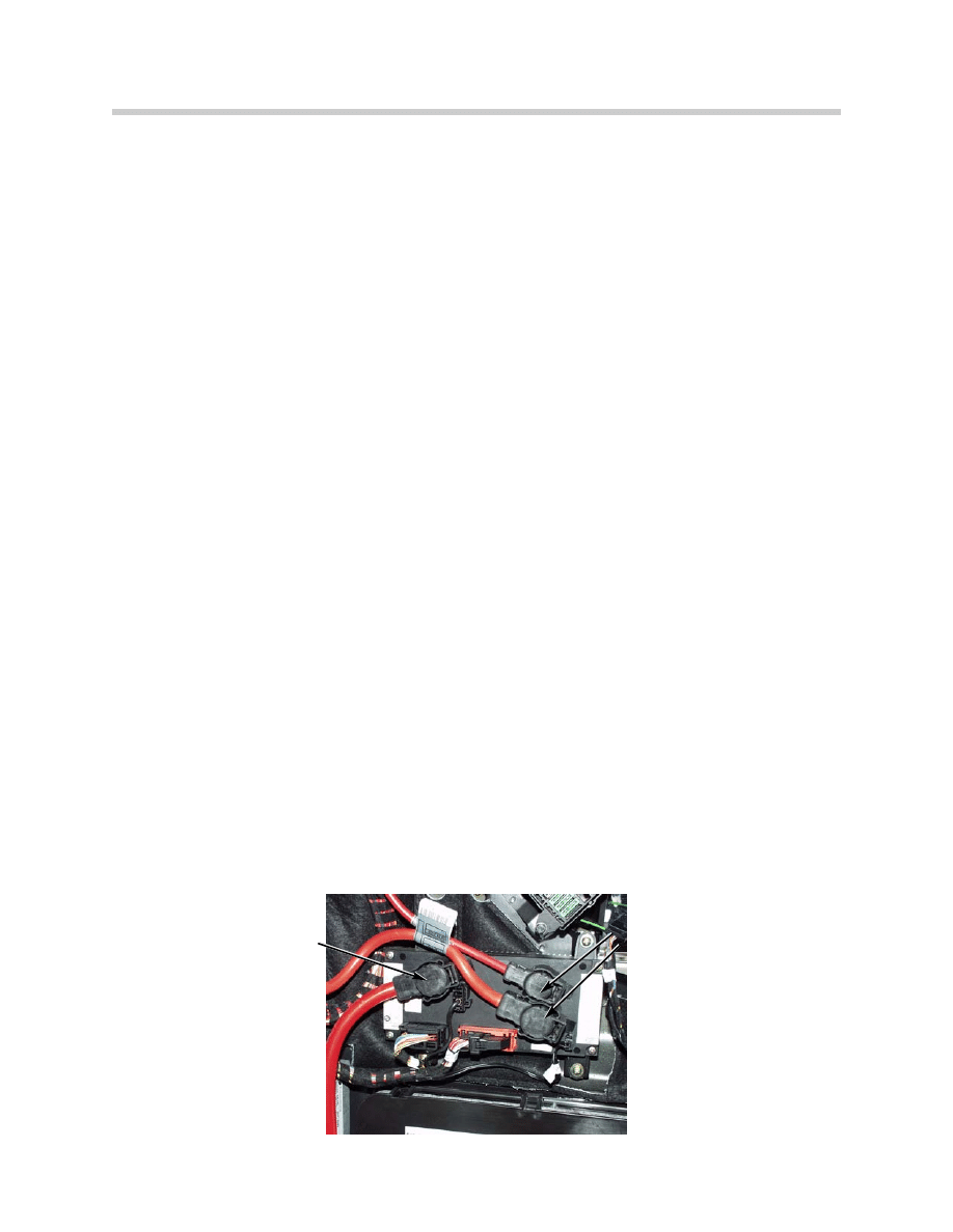
High Current Terminals (RADSOK)
New high current terminals are used for the first time. The high current terminals are on
the input terminal 30 and the outputs terminal 30U and 30B. These contacts are capa-
ble of carrying current peaks (short term) of 220A.
Advantages:
• Continuous load capacity of up to 100A
• Excellent and consistent current conduction over long periods
• Low contact resistance
• Low voltage drop even in the event of a large temperature rise
• Consistently good spring characteristics
• Contacts are self cleaning
The contact are coated in a silver alloy. As compared to tin, nickel, gold and copper, silver
has the lowest specific electrical resistance.
In spite of high currents, the high current sockets are not soldered to the cable, as a spe-
cial crimping technique ensures an excellent connection.
RADSOK Terminals
RADSOK Terminals
13
E65 Power Module
Power Module Inputs
Terminal 30
The battery positive terminal is connected directly to the load input of the Power Module.
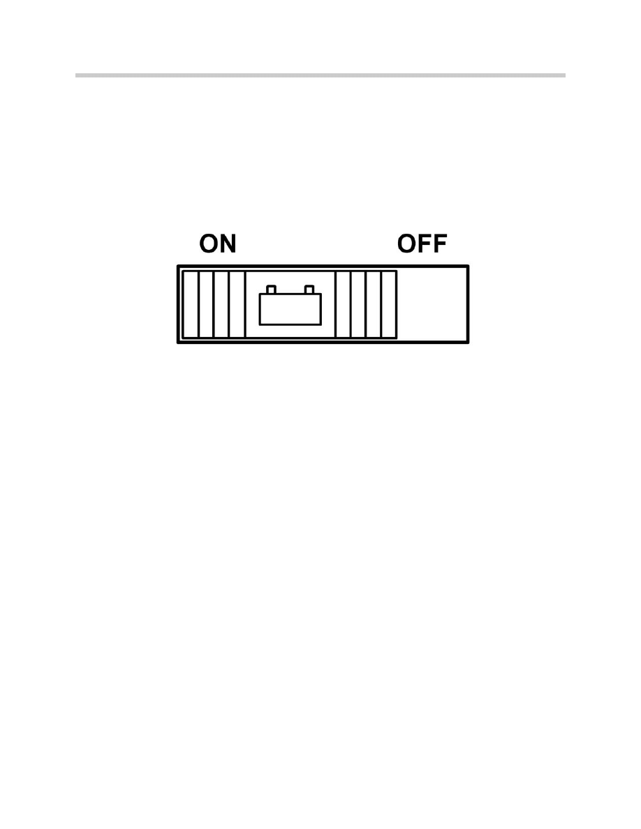
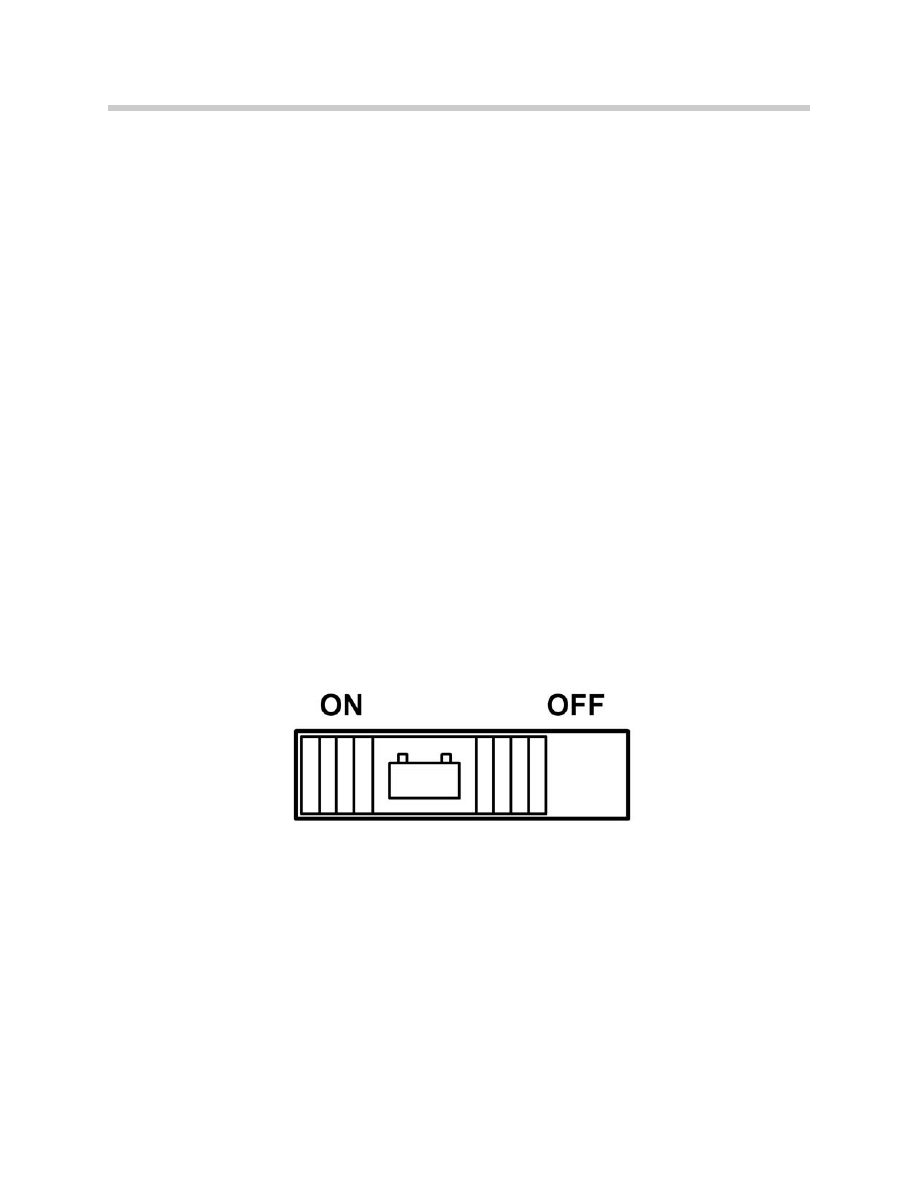
Battery Switch
The battery switch (BS) offers the vehicle owner and the service department the choice
between the settings ON ("closed circuit current monitoring") and OFF ("storage mode").
It is located above the PM on the right hand side of the luggage compartment.
Interior Lighting Button
This controls the interior lighting and is located on the front interior lighting unit. The pos-
sible settings are "Automatic control", "On" , "Off" and “Workshop mode” (hold for 3 sec-
onds).
Exterior Trunk Lid Release Button (TOEHK)
This button is a direct input to the Power Module. The trunk lid is released by means of
the button on the outside of the trunk lid.
Trunk Lock Actuator Switch
The switch in the trunk lock actuator is used to inform the Power Module as to the posi-
tion of the lock actuator and to synchronize the SCA. it also controls the luggage com-
partment lighting, the monitoring of the alarm system and the trunk lid warning light.
SCA Contact
This input is used to signal the PM that the SCA has rotated 180° (used to switch
the electric motor).
15_w (Wake-up)
This is a redundant signal from the Car Access System which wakes up the Power
Module.
Battery Temperature Sensor
Measures the temperature directly on the battery negative terminal. This information is
used for the "optimum charging" function. The measuring range is -25°C to +75°C.
K-CAN Periphery
Enables communication with the vehicle network.
14
E65 Power Module
Outputs Connected to Electronic Battery Master Switch
Terminal 30U
Supplies the fuse box in the luggage compartment.
Terminal 30B
Supplies the fuse box in the glove compartment.
Outputs not Connected to Electronic Battery Master Switch
The following outputs are supplied by the PM separately from the electronic battery
master switch:
• Rear window heater (HHS)
• Light Module (LM)
• Car Access System (CAS)
• DME
• Alarm system (DWA)
• Emergency power siren (SINE)
• Cigarette lighter (ZIG)
Battery Switch
Terminal 30U
Battery Switch
Terminal 30B
• Electro-chromatic mirrors (EC)
• Park Distance Control (PDC)
• Rain/light sensor (RLS)
• Interior lighting (IB)
• Central locking trunk lid drive (ZV)
• Central locking, fuel filler flap (ZV)
• Trunk lid Soft Close Motor (SCA)

15
E65 Power Module
The advantages of this arrangement are:
• The exterior lighting can remain on (for safety reasons) even if the electronic battery
master switch is off.
• The alarm system is always armed.
• No additional fuses and wiring for actuators in nearby locations.
Fuses
The outputs for the rear window heater, Terminal R and Terminal 15, are not protected by
conventional fuses. They are supplied via a power transistor (MOS-FET) in the Power
Module.
By measuring the current and comparing it with stored threshold levels, the Power
Module can detect a short circuit and disconnect the circuit if needed. The outputs for
CAS, DWA system and DME are protected by internal electronic fuses: F1, F2 and F3.
Notes:
16
E65 Power Module
Power Module Functions
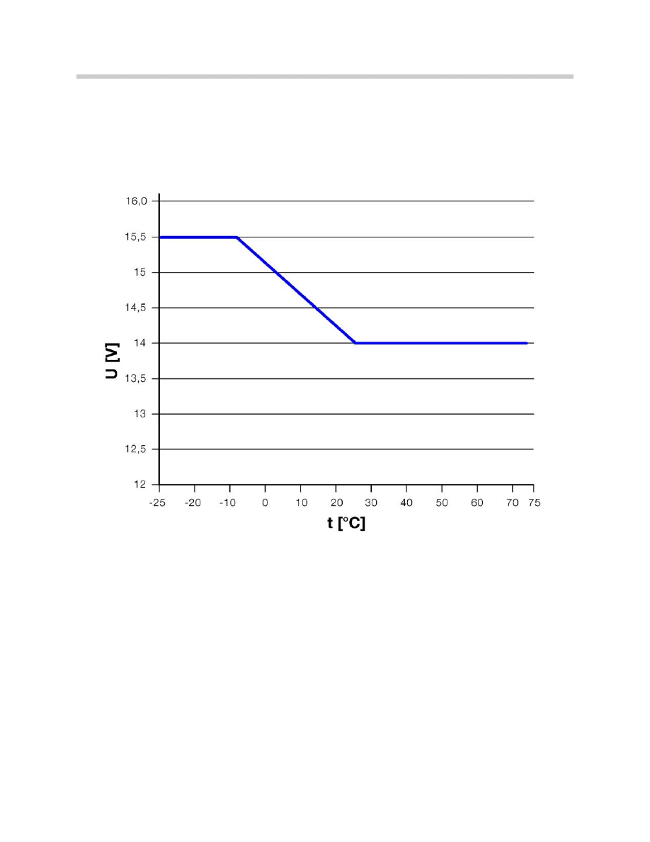
Optimum Charging
The battery voltage can fluctuate between 14.0 V and 15.5 V. The optimum charge volt-
age is set according to the charge level of the battery, the battery temperature and the
status of the external lights (higher charging voltage with lights off). The maximum set-
ting is 16 V.
Battery Charge Level Detection
The Power Module knows what the charge level of the battery is at any time by calculat-
ing the battery current when the vehicle is being driven and measuring the discharge cur-
rent.
When the vehicle is not in use, the charge level is re-calculated and updated by measur-
ing the closed circuit battery voltage. If the vehicle battery is replaced it must be regis-
tered with the Power Module so that the stored values can be deleted and a new calcula-
tion started. This operation is described in “Service Functions”.
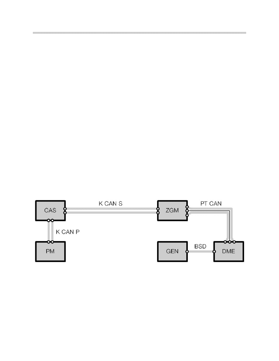
Temperature-Dependent Battery Charging Voltage
By using a charging characteristic map stored in the PM, the charge voltage of the gener-
ator is adjusted according to the battery temperature. The diagram below shows the
communication path necessary for the Power Module to inform the generator to increase
or decrease charge voltage output.
The Power Module detects the temperature of the battery and places the instruction
"Increase charge voltage" on the K-CAN Periphery. The Car Access System (CAS) pass-
es the message on to the K-CAN System bus.
The Central Gateway Module (ZGM) receives the message. Performing its function as a
"gateway control unit", it passes the message on to the PT-CAN.
The DME (ECM) module receives the request to increase the charge voltage over the
PT-CAN.
17
E65 Power Module
The generator then receives the request to increase the charge voltage via the BSD lead
(bit serial data interface). The electronic evaluation unit in the generator then adjusts the
charge voltage accordingly.
If the temp. sensor is detected as defective then the charging voltage will be fixed at
14.3V.
Increasing Idle Speed to Improve Battery Charging
In order to drain as little energy as possible from the battery during freezing weather
(below 34°F) the idling speed may be increased.
This ensures that the battery charge level is kept high. If the charge level falls below the
calculated minimum level for starting, the idling speed is increased to 750 rpm.
The calculation of the minimum level for starting takes account of the temperature and
the condition/age of the battery.
18
E65 Power Module
Load-Circuit Peak Reduction
If battery discharge is detected while the engine is running (despite increased idling
speed), the power supply to electrical consumer circuits are gradually reduced or com-
pletely shut off according to a table of priorities. The consumer systems concerned are
divided into two groups: Priority group A and Priority group B.
Priority A systems are dependent on battery SoC (State of Charge) and generator output
during the operation of the consumer.
Priority B systems are only dependent on the battery SoC.
The Power Module also sends out a telegram indicating the status of the Load-circuit
peak reduction function. The priority level of the message is classified by a number 0
through 6 and is as follows:
• 0 = Normal operation without peak reduction (KL 15 “ON”)
• 1 = Terminal R “ON” without peak reduction
OR generator defect
or under-voltage acknowledged.
• 4 = Corresponds to maximum peak reduction.
• 5 = Corresponds to medium peak reduction.
• 6 = Corresponds to minimum peak reduction.
The computation by the Power Module to determine which priority level is necessary is
based on the battery SoC. Example: the threshold for priority level 6 is a 65% SoC.
Current vehicle priority levels can be displayed in the Diagnosis Program.
Priority Group A
Priority Group B
Rear window heater
IHKA fan (Except during defrost)
Headlight washing
Rear IHKA fan (E66 only)
All seat heaters
Active seat
Seat ventilation
Steering wheel heater
Mirror heater
Windshield wiper blade heating
Wet arm heating
19
E65 Power Module
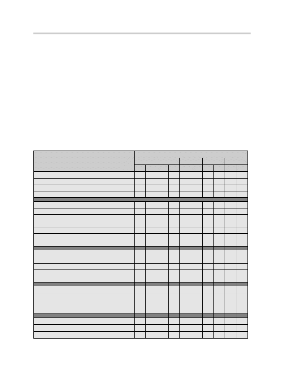
Priority Table for Load-Circuit Peak Reduction and Shut-Down Modes
Legend:
• X = Permitted operation at the priority level concerned
• PM bus telegram priority A devices = Control peak reduction-priority
• PM bus telegram priority B devices = Control peak reduction-comfort
• Priority level:
0= Normal operation without peak reduction (KL 15 “ON”)
1= Terminal R “ON”, generator defect or under voltage acknowledged.
4= Corresponds to max. peak reduction.
5= Corresponds to medium peak reduction
6= Corresponds to minimum peak reduction
Consumer Circuit
Priority Level
0
1
4
5
6
A
B
A
B
A
B
A
B
A
B
Rear Window Defogger
Off
X
X
X
X
X
Intermittent operation
X
X
X
On
X
Seat Heaters
Switched off
X
X
X
X
X
Temperature level 1
X
X
X
X
Temperature level 2
X
X
X
Temperature level 3
X
Maximum rated output
X
X
Half rated output
X
X
X
X
Heater Fan
Speed 0
X
X
Speed 1
X
X
X
X
Speed 2
X
X
X
X
Speed 3
X
X
X
Steering Wheel Heater
Level 0
X
X
X
X
X
Level 1 (clocked mode)
X
X
X
Level 2 (fast heat up)
X
X
Mirror Heater
Off
X
X
X
X
X
On
X
20
E65 Power Module
Shut-Down of Consumer Circuits in the Event of Low Voltage
If the battery voltage drops below 10.5 V (for 5 seconds) due to high load levels, the
Power Module sends out an instruction to increase the idling speed and to activate priori-
tized shut-down of electrical consumer circuits.
At the same time, the power outputs of the Power Module (interior lighting, consumer
isolation circuit in roof/body zone) are switched off.
The following Check Control message appears:
Consumer Circuit
Priority Level
0
1
4
5
6
A
B
A
B
A
B
A
B
A
B
Windshield Heater
Off
X
X
X
X
X
On
X
Wet Arm Heater
Off
X
X
X
X
X
On
X
Headlight Washer System
Off
X
X
X
X
X
On
X
Active Seat
Off
X
X
X
X
X
On
X
X
Seat Ventilation
Off
X
X
X
X
X
On
X
X
X
Check Control Message Displayed in
KOMBI
Message displayed in Control
Display
Cause
Power Module! Drive Moderately
Power Module in emergency operating mode.
Electrical power supply limited. Please con-
tact nearest BMW center.
Power Module con-
ducting emergency
shut down mode
CC Symbol Displayed

21
E65 Power Module
16 Minute Shut-Down of Consumer Circuits (Sleep mode)
To prevent battery discharge by consumer items mistakingly left on, the interior lighting
circuit (IB) and consumer circuits-roof zone (VA-D) are shut off 16 minutes after terminal
R is switched off.
Shut-Down of Auxiliary Consumers
Auxiliary consumer circuits are items such as the CD, DWA, LM, EGS and IHKA
(rest function).
In order to ensure that the car is capable of starting, the charge level (SoC-State of
Charge) of the battery is monitored when the vehicle is at rest.
The minimum battery SoC required to ensure that the car can be started again is
a calculated value. The calculation takes into account the:
• Battery temperature measured over last few days
• Engine type
• Capacity of the battery fitted (110Ah for the 745i).
The SoC calculation is displayed as a percentage of battery capacity ( A fully charged
battery is considered 80%).
If the charge level of the battery gets close to that calculated minimum level as a result
of the operation of an auxiliary consumer unit, the Power Module instructs that circuit to
switch off.
Two modes of operation are distinguished when shutting down auxiliary consumer
circuits:
• Auxiliary consumer with terminal R on.
• Auxiliary consumer with terminal 0 (ignition off).
22
E65 Power Module
Auxiliary Consumers and Terminal R
When terminal 15 changes to terminal R, the message Priority level 1 is broadcast.
Reduction of power consumption if necessary is then controlled on the basis of the table
on page 18 and 19.
The charge level of the battery is calculated. If it is still below the minimum level for start-
ing the car, the following Check Control message appears:
If the charge level does not improve, after 5 minutes the PM issues the "Shutdown
counter" message (shut-down message is to inform modules to store any information
prior to power being switched off). After a further 90 seconds, the vehicle's electrical
system is shut down.
This is on condition that no safety related consumers are switched on.
If safety related consumers are on (e.g. hazard lights), the battery is not disconnected
from the electrical system when the minimum battery SoC for starting the car is reached.
The battery is allowed to fully discharge.
Auxiliary Consumers and Terminal 0
If the driver switches on an auxiliary consumer it logs itself on by issuing the message
"Auxiliary consumer power management". By doing so, it triggers the PM to precisely
calculate the battery charge level.
Following a successful log-on, the auxiliary consumer goes into operation and the charge
level of the battery is monitored.
If the charge level falls below the minimum level for starting the car, the following Check
Control message appears:
Five minutes later, if no legally required consumers are switched on, the PM automatically
switches to "closed-circuit current monitoring" mode.
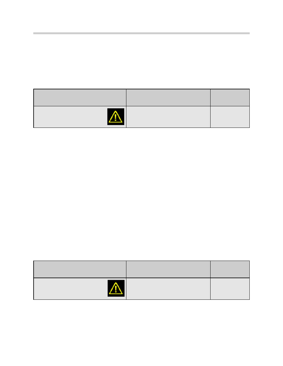
Check Control Message Displayed in
KOMBI
Message displayed in Control
Display
Cause
Recharge Battery!
Recharge Battery! Battery heavily dis-
charged. Charge by driving for longer period
or by using external charger. Battery will be
disconnected soon.
Battery discharged
Check Control Message Displayed in
KOMBI
Message displayed in Control
Display
Cause
Recharge Battery!
Recharge Battery! Battery heavily dis-
charged. Charge by driving for longer period
or by using external charger. Battery will be
disconnected soon.
Battery discharged
23
E65 Power Module
Closed-Circuit Current Monitoring (Standby Current)
When terminal 0 is active, the PM switches over to closed-circuit current monitoring after
60 minutes. If an operation is performed on the car before 60 minutes has elapsed (e.g.
central locking, trunk opened), the timer starts from the beginning again.
Once that period has ended, the closed-circuit current should not exceed 80 mA. If the
closed-circuit current exceeds 80 mA, after 5 minutes the PM issues the "Shutdown
counter" message. After a further 90 seconds, the vehicle's electrical system is shut
down for 5 seconds.
If the quiescent current still exceeds 80 mA when the system is switched on again, the
sequence described above is repeated. If the quiescent (sleep) current is then still over
80 mA, the system is permanently shut down via the electronic battery master switch.
The fault is recorded in the Power Module's fault memory (with details of environmental
conditions and cause).
When the signal “15w” from the CAS is detected, the electronic battery master switch
is closed and the following Check Control message is displayed:
Closed-circuit current monitoring is automatically cancelled by a message from the
LM that the hazard warning lights are active.
When terminal R is switched off, current monitoring is also immediately activated.
Normal current load on the vehicle drops in stages according to the vehicle programming
for sleep mode (see the chart on the following page).
If the monitored current is more than 120 amps (even as a random spike) , the interior
lighting, roof area consumers and body zone consumer circuits are immediately
switched off.
Check Control Message Displayed in
KOMBI
Message displayed in Control
Display
Cause
High standby current!
High standby current! Vehicle electrical
accessories are drawing excessive passive
state current. Battery has been disconnect-
ed, Please contact your BMW center.
Excessive closed
circuit current draw.
24
E65 Power Module
Closed Circuit Consumer Monitoring and Vehicle Sleep Mode
Notes:
Bus communication ended: Vehicle in sleep mode! Indicator: CAS lighting out
800 mA
Sleep mode: VA-D (consumer circuit-roof) switched off
Indicator: BZM lighting (seat switches) out, trunk light out.
12 A
50mA
200 mA
25 Seconds
16 Minutes
1 Hour
Sleep mode: VA-K switched off.
• Cigarette lighter relay
• Telephone
• Power module
B
us
telegr
am: “Sleep count
er”
25
E65 Power Module
Storage Mode
By switching “OFF” the battery switch, the
Power Module goes into Storage Mode 30
minutes after terminal R switches off.
Before disconnecting, the PM sends out the "Shutdown" signal. After a further 90 sec-
onds the shut down is completed. If the ignition switch is turned to terminal R “On”, a
Check Control message is issued which informs the driver that the vehicle is in Storage
Mode.
The following CC message appears:
When the signal “15w” or change-over of the battery switch to "closed-circuit current
monitoring" is detected, the electronic battery master switch is closed.
The car can still be started and driven in storage mode. All systems remain functional.
The CC message remains active.
When "Terminal R Off" is active, disconnection is carried out after 30 minutes (as
explained above).
Note: If no function of any kind is activated over a period of 3 weeks, the bat-
tery is disconnected completely from the vehicle's electrical system.
This prevents battery discharge. This function is independent of the
position of the battery switch.
Electronic Fuse
If a short circuit current of over 250 A is detected, the battery master switch is opened.
When the wake-up signal “15w” from the CAS is detected, then an attempt is made to
close the battery master switch again.
This procedure is repeated continually until the short circuit has been eliminated.
Check Control Message Displayed in
KOMBI
Message displayed in Control
Display
Cause
Battery Switch OFF!
Battery Switch OFF! Re-set battery switch in
luggage compartment to ON, refer to owners
manual.
Battery switch left in
OFF position.

26
E65 Power Module
Central Battery Voltage Notification
The Power Module continuously measures the battery voltage. This information is made
available to all other control units via the bus link. This can be used, for example, to enable
continuous running of the sliding/tilting sunroof regardless of battery voltage.
Central battery voltage notification eliminates the need for individual measurement of bat-
tery voltage by each control unit.
Rear Window Heater (HHS)
The electronic rear window heater output stage of the PM is activated by a "HHS On" (K-
CAN-S via CAS via K-CAN -P) message from the IHKA control unit. Control is directly by
the final stage.
Interior Lighting
The interior lighting is subdivided between three outputs (groups):
• IB (interior lighting)
• VA-K (consumer isolation circuit, body zone)
• VA-D (consumer isolation circuit, roof zone)
The interior lighting is controlled by the PM, the outputs are 12V stabilized-voltage.
VA-K and VA-D are switched on/off according to the status of the relevant switches.
Trunk Lid and Fuel Filler Flap Control
The Power Module controls the following trunk-lid related functions of the body zone
electronics:
• Trunk lock actuator
• Trunk lid automatic soft close motor (SCA)
• Fuel filler flap lock actuator
The necessary software, such as on times and repeat lockouts is integrated in the PM.
For more details, refer to the chapter: Central Body Electronics.
The PM monitors the trunk lid for the DWA system via the trunk lock actuator (ZV) con-
tact switch.

27
E65 Power Module
Data Memory
The data memory stores data relevant to the vehicle. That information provides a status
read-out of the battery load and life. It can be accessed by way of the diagnosis function.
The data memory will be used in future to obtain a load profile of the battery in normal
operation that will be analyzed for the purposes of "condition based servicing."
Emergency-Mode Functions
Battery Temperature Sensor
In the event of a defective sensor, a short circuit or an implausible value, the substitute
value of 20°C is assumed. This corresponds to a fixed charge voltage of 14.3 V at the
battery.
Battery capacity (SoC) is calculated using the substitute value.
Battery Switch
If a fault is detected in the battery switch, the Power Module switches to Storage
mode as if the switch were in the “OFF” position.
Terminal 15w
Shut-down of the PM in the absence of terminal 15w is prevented by the following
duplicated signals:
• Terminal 15 (from CAS via bus link)
• Road speed > 2 km/h (from DSC via bus link)
• System voltage > 13.2 V (PM central battery voltage notification)
Bus Communication
If bus communication is not possible, all information is "frozen."
28
E65 Power Module
Summary of Check Control Messages for Power Module
The following is a summary of all of the possible Check Control messages relevant to the
Power Module:
Check Control Message
Displayed in KOMBI
Message displayed in
Control Display
Cause
Battery Switch OFF!
Battery Switch OFF! Re-set
battery switch in luggage
compartment to ON, refer to
owners manual.
Battery switch left in
OFF position
High standby current!
High standby current! Vehicle
electrical accessories are
drawing excessive passive
state current. Battery has
been dis-connected, Please
contact your BMW center.
Excessive closed circuit
current draw.
Recharge battery!
Recharge battery! Battery
heavily discharged. Charge
by driving for longer period or
by using external charger.
Battery will be disconnected
soon.
Battery discharged.
Power Module!
Drive moderately.
Power module in emergency
operating mode. Electrical
power supply limited. Please
contact the nearest BMW
center.
Power module in emer-
gency mode.
Power module failure!
Power module failure!
Automatic monitoring of bat-
tery charge level failure.
Please contact the nearest
BMW center.
Power module alive sig-
nal missing over bus
line.
29
E65 Power Module
Workshop Hints
Battery Charging
As with previous models, a battery charger can be connected in the engine compartment
to the battery junction point or directly to the battery in the trunk. The PM detects an
external battery charger if the battery voltage is above 13.2 V for 1 hour without the
engine running.
Following detection of external battery charging, a battery charge level of 80% is reported
even if the charge level is higher or lower than that figure.
Cigarette Lighter Battery Charging Function
A trickle charger can also be connected to the cigarette lighter. However, the cigarette
lighter is supplied by the body-zone consumer isolation circuit (VA-K) via a relay.
If the "terminal R Off" signal is present for more than 60 minutes, that relay will be
switched off by the consumer shutdown function. That would mean that a charger con-
nected to the cigarette lighter would be disconnected from the battery.
To prevent this, the consumer shut-down function can be deactivated. This is performed
by the following procedure:
Slide the battery switch off and on again twice within two seconds. Starting with the
battery switch in the ON position, switch to OFF, Switch ON, Switch OFF and end with
the switch in the ON position. Do this within 2 seconds, an the trickle charger can be
used to charge the battery through the cigarette lighter.
The function is cancelled by: "terminal 15 On" , switching the battery switch from "OFF"
to "ON" or failure of the battery voltage to reach 12.6 V after 6 hours of charging.

30
E65 Power Module
Diagnosis
All inputs/outputs that are part of the Power Module can be diagnosed by Test Modules
or status checked by the Control Unit Functions of the Diagnosis Program. The outputs
can also be activated by Component Activation and the power consumption displayed.
The Diagnosis Program is based on the E46 concept.
All electronic fuses and the electronic battery master switch are monitored for short cir-
cuits/circuit breaks. In the event of a fault, an appropriate entry is made in the PM's fault
memory and, if appropriate, a check control message initiated.
Service Functions
Sleep Mode Activation
This function can be used to put the control units into sleep mode. The battery switch
must be set to “ON” when using this feature. The Test module will indicate whether the
function was successful or not.
Battery Replacement Registration
This Service Function informs the PM that the battery has been replaced. It completes
the following operations:
• The battery capacity is set to 80%.
• The current odometer reading is stored.
The odometer readings at which the last seven battery replacements took place can be
read off from the Diagnosis Requests of Control Unit Functions.
• The stored battery statistics (current, voltage, battery charge level) are deleted.
• The stored temperature statistics are deleted.
Transport Mode Clearing
Vehicles that arrive at the BMW centers may have the Transport Mode cleared by using
the Test Module under the Service Functions menu. Different from the Storage Mode
described on page 24, certain consumers such as the radio, interior lights, and electric
windows (except drivers side) are permanently switched off.

31
E65 Power Module
Workshop Exercise - E65 Power Module
Using an instructor designated vehicle, perform a complete vehicle short test. Also
locate the Power Module in the vehicle.
After the short test, go to “control module functions” and access the Power Module
diagnostics. Go the the “activate components” screen and select the
“deactivate/activate electrical loads - body” menu.
What systems/components are affected when this circuit is de-activated? (hint: Use ETM)
Go the the “activate components” screen and select the “deactivate/activate electri-
cal loads -
roof ” menu.
What systems/components are affected when this circuit is de-activated? (hint: Use ETM)
Why is the trunk lid release circuit a direct output of the power module?
Notes:

32
E65 Power Module
Workshop Exercise - Diagnosis
Using an instructor designated vehicle, perform a complete vehicle short test.
Diagnose complaint as directed by instructor. Complete worksheet using the proper
“Complaint, Cause and Correction” format.
Vehicle:
Chassis #:
Production Date:
Complaint:
Cause:
Correction:

33
E65 Power Module
Classroom Exercise - Review Questions
1.
What is the maximum charging voltage on an AGM battery?
2.
List the pathway in which the power module commands the generator to adjust
the charging voltage:
3.
Why is the Power Module responsible for controlling the trunk and filler flap lock
actuators?
4.
What information does the Power Module use to calculate the optimum charge
voltage?
5.
Name a feature of the Power Module that is responsible for ensuring that the
important systems have power, even of a voltage loss while driving is detected.
How can the Power Module react to a loss in power?

34
E65 Power Module
6.
What function must be performed to the Power Module after relacing a battery?
7.
How would the driver know that the battery switch was in the OFF position?
8.
How is the Power Module informed that an external battery charger has been
connected?
9.
Which control module provides the KL15w (wake-up) signal to the Power
Module? What would happen if the wire for the KL15w input were damaged?
10.
What happens to the engine RPM if the charge level falls below the calculated
minimum level for starting?
Document Outline
- Main Menu
- Intro to Advanced Body Electronics
- E65 Power Management
- E65 Power Module
- E65 Car Access System
- E65 Driver Information
- E65 Body Electronics
- E65 Central Body Electronics
- E65 Remote Control Services
- E65 Automatic Trunk Lid Lift
- E65 Windshield Wiping Washing
- E65 Seat, Mirror and Steering Column
- E65/66 Model Update
- E65/66 Comfort Access
- E6x Voltage Supply and Bus Systems
- E6x Body Electronics
- E6x Body Electronics
- E6x 9/05 Model Updates
- E6x Driver Information Systems
- E90 Voltage Supply and Bus Systems
- E90 General Vehicle Electrical
- E90 General Vehicle Electrical
- E90 General Vehicle Electrical II
- E90 Driver Information Systems
- E90 Entertainment and Communication
- Car Communication Computer
- Head-Up Display
- Head-Up Display (First Generation)
- E70 Head-Up Display (Second Generation)
- E70 Audio Systems
- BMW Night Vision
- Glossary
Wyszukiwarka
Podobne podstrony:
04 E65 Power Module
[EP 2003] 1381775 WIND TURBINE POWER MODULE MOUNTED ON THE TOWER FOUNDATION
Ambient Power Module
[EP 2003] 1381775 WIND TURBINE POWER MODULE MOUNTED ON THE TOWER FOUNDATION
MDF CP4 power suply on connunication module
An 9021 A Novel Igbt Inverter Module For Low Power Drive Applications
prezentacja power media
02a URAZY CZASZKOWO MÓZGOWE OGÓLNIE 2008 11 08
Power D, zebranie zarządu
karty płatnicze (power point)
elastyczność popytu (power point)
kryptologia w bankowości (power point)
MT st w 02a
europejski system nagród (power point)
TQM zarządzanie jakością (power point)
V80 Power Management 11May04
Popular Mechanics Repairing Power Antennas
więcej podobnych podstron