62
12-2009 elektor
The Vikings Are Coming!
Bluetooth with the ATM18
ATM18 SERIES
The unusual name ‘Bluetooth’ is a homage
to the Danish Viking King Harald (in Dan-
ish, Harald Blåtand), who was born in 911
and died on 1 November 987. He united 960
large regions of Scandinavia, and he was
known for his communication skills. Harald
Blåtand also introduced Christianity to the
majority of Denmark. The choice of name
is connected with the participation of Eric-
sson in the development of the Bluetooth
standard under the leadership of Dr Sven
Mattisson, a Swede. As the objective of this
By Wolfgang Rudolph and Detlev Tietjen (Germany)
Since its introduction in 2001, Bluetooth has developed into an essential standard for wireless links
between devices. Using an inexpensive serial module, we can add Bluetooth functionality to our
ATM18 board. Naturally, the example software written in C can also be adapted for use with other
ATmega boards.
63
elektor 12-2009
technology is to unite all modern devices
and allow them to communicate with each
other, the developers (including Professor
Jaap Haartsen, a Dutchman) agreed on the
name ‘Bluetooth’. The Bluetooth logo con-
sists of the runic symbols for ‘H’ and ‘B’ on
top of a blue background (Figure 1).
In a project published in the January 2009
issue of Elektor [1], we interfaced a radio mod-
ule with the ATM18 board to give it wireless
data communication capability. Although
Bluetooth is also a wireless data transmission
interface, it operates in a different ISM fre-
quency band (2.4 GHz) and uses a consider-
ably more complex protocol. The Bluetooth
standard has been described extensively in an
Elektor article [2], and of course you can find
descriptions of this standard on many web-
sites, so we do not need to describe it in detail
here. With a Bluetooth interface, the ATM18
board can establish a connection not only
to a PC or another ATM18 board, but also to
any other device equipped with a Bluetooth
interface. To make this all possible, we first
have to integrate a Bluetooth module with
the ATM18 board.
Module selection
Although commonly available Bluetooth
adapters in the form of USB sticks have
become exceptionally cheap now, they can
only be used with a USB host device such
as a PC. For connection to our microcon-
troller board, we need a Bluetooth mod-
ule with a serial interface. Serial Bluetooth
adapters of this sort are used primarily in
industrial applications, and unlike Blue-
tooth USB sticks they are not consumer
goods. Although quite a few types are avail-
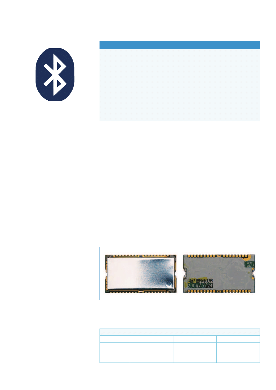
able, most of them are not cheap. We found
a module from Rayson, with type number
BTM-222 (Figure 2), that is fairly inex-
pensive. It is a Class 1 device with an out-
put power of 18 dBm. Class 1 devices (see
Table 1) have the highest transmit power,
with a range of more than 100 metres
(300 ft.) in free space. The key features
are listed in the ‘Module features’ inset.
The data sheet is available on the Internet
via a link on the Elektor web page for this
article [3]. The module supports the Hayes
modem command set, which makes it easy
to operate from a PC with a terminal emu-
lator program. After start-up, the module
initially evaluates all characters received
via the serial interface as commands. After
a connection is established, the characters
(data) are simply forwarded to the party at
the other end.
Bluetooth profile
Profiles are used for data exchange over the
Bluetooth interface. During link setup, the
devices exchange information about their
profiles and agree on the profile to be used.
The BTM-222 module used here supports
the serial port protocol (SPP). This means
that the module acts like a COM port on
one side and like a UART (with TxD and RxD
signals) on the other side. This sort of con-
nection is sometimes called a ‘virtual cable’.
From the perspective of the application
software and the connected hardware, this
wireless link behaves the same way as a
serial link using a cable.
Bluetooth board
The BTM-222 module consists of a small PCB
fitted with SMD components and covered
by a protective metal shell. With dimen-
BTM-222 Bluetooth module features
Certified for Bluetooth Version 2.0 and EDR
Direct line-of-sight range with lambda/4 antenna (31 mm): 80–150 m (depending on
weather conditions)
Transmit power (Class 1): 18 dBm max.(63.1 mW into 50 Ω)
Low power consumption (hold, sniff, park, and deep sleep mode)
Supply voltage: 3.0–3.6 V
Full Bluetooth data rate via UART
Supports up to seven ACL links and three SCO links
Supports enhanced data rate (EDR) for both modulation modes (2 Mbps and 3 Mbps)
SPP firmware with AT commands
Dimensions (mm): 28.2 x 15.0 x 2.8
•
•
•
•
•
•
•
•
•
•
Figure 1. The Bluetooth logo consists of
the runic symbols for ‘H’ and ‘B’ against a
blue background.
Table 1. Bluetooth classes and operating ranges
Class
Max. power
Max. power
Free-air range
1
100 mW
20 dBm
approx. 100 m
2
2.5 mW
4 dBm
approx. 50 m
3
1 mW
0 dBm
approx. 10 m
Figure 2. The BTM-222 Bluetooth wireless module transmits with high power (Class 1) and
has a serial data interface. It is soldered to the PCB in Figure 4 like an SMD component.
64
12-2009 elektor
sions of 28
r 15 mm, it looks a bit like an
overgrown 38-pin DIL SMD IC. It has stubby
leads along the sides that can be used to
solder the module to a circuit board in the
same way as an SMD device. A circuit (Fig-
ure 3) and accompanying PCB (Figure 4)
for the module have been designed in the
Elektor labs.
The PCB is designed to accept the BTM-
222 module (serial interface) as well as the
BTM-220 module, which has an additional
USB port. We used only the BTM-222 for our
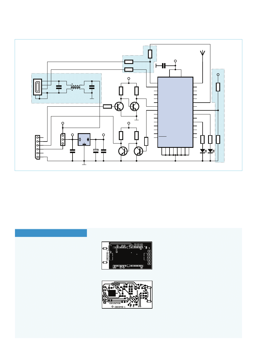
Figure 3. Circuit diagram of the Bluetooth PCB with the BTM-222 module. The components marked with an asterisk (*) are for the USB
interface and are only necessary if the board is used with a BTM-220 module.
1
3
2
IC2
LF33
6V3
C2
10u
C1
100n
C3
100n
K1
+5V
+3V3
ANT1
+3V3
1
2
3
4
L1
1
2
3
4
6
RXD
TXD
+5V
GND
5
4
3
2
1
5
6
K2
C4
100n
JP1
C5
100n
T1
BC847
T2
BC847
T4
BC847
T3
BC847
R1
1k
R2
1k
R3
1k
+5V
PVCC
2
VCC
17
G
N
D
1
G
N
D
10
G
N
D
18
G
N
D
19
G
N
D
29
G
N
D
38
G
N
D
39
G
N
D
40
AIO(0)
3
AIO(1)
4
PIO(0)
5
PIO(1)
6
PIO(2)
7
PIO(3)
8
PIO(4)
9
PIO(5)
11
PIO(6)
12
PIO(7)
13
PIO(8)
14
PIO(9)
15
PIO(11)
35
PIO(10)
36
RESET
16
USB_DP
20
USB_DN
21
PCM_SYNC
22
PCM_IN
23
PCM_OUT
24
PCM_CLK
25
UART_RX
26
UART_TX
27
UART_RTS
28
UART_CTS
30
SPI_MOSI
31
SPI_CSB
32
SPI_CLK
33
RF_IO
37
SPI_MISO
34
IC1
BTM222
R5
1
k
R6
1
k
+3V3
R4
1k
D1
D2
R7
1
k
R8
1
k
R12
27R
R13
voir texte
27R
R11
1
k
5
R9
4
7
k
R10
2
2
k
+5VUSB
+5VUSB
C6
100n
USB
CC2
USB-B
080948 - 11
*
*
*
*
*
*
*
*
*
*
*
*
COMPONENTS LIST
Resistors
R1–R8 = 1kΩ SMD 0805
Capacitors
C1,C3,C4 = 100nF SMD 0805
C2 = 10µF 10V SMD 1206
Semiconductors
D1 = LED, red, SMD 0805
D2 = LED, green, SMD 0805
T1–T4 = BC847, SMD (SOT-23)
IC1 = BTM-222, Bluetooth module, from Ray-
son Technology*
IC2 = LF33C or LF33CDT, DPAK-case, (e.g. Far-
nell # 1087187)
Miscellaneous
K1 = 6-way socket strip, right angled
JP1 = 3-pin header with jumper (or wire link)
PCB # 080948-1*
* available from the Elektor Shop or www.
elektor.com/080948
Addiional parts if IC1 = BTM-220 instead of
BTM-222
Resistors
All SMD 0805
R9 = 47kΩ
R10 = 22kΩ
R11 = 1.5kΩ
R12,R13 = 27Ω
Capacitors
C5,C6 = 100nF SMD 0805
Inductor
L1 = 2200Ω @ 100MHz, e.g. Murata DL-
W31SN222SQ2L (Farnell # 515599)
Miscellaneous
K2 = USB plug, type A, SMD, e.g. Lumberg
2410 07 (Farnell # 1308875)
Figure 4. A few SMD components are fitted
on the front side of the board, while only
the BTM-222 module is fitted on the rear.
65
elektor 12-2009
application with the ATM18, which means
that the components on the schematic
diagram inside the highlighted boxes with
dashed outlines are not fitted. The compo-
nents that are only necessary for the BTM-
220 are also shown separately in the com-
ponents list.
The operating circuit for the BTM-
222 module, as shown in Figure 3,
consists of only a few components.
K1 is a socket header for connec-
tion to the serial port of the ATM18
board. This connector in combina-
tion with jumper JP1 (in position
CC2) supplies the circuit with +5 V
from the ATM18 board. Voltage reg-
ulator IC2 reduces this to the 3.3-V
operating voltage of the wireless
module. Level conversion for the
serial interface (5 V
3 V) is pro-
vided by transistors T1 and T2 for
TxD and transistors T3 and T4 for
RxD. Two LEDs are also connected
to the wireless module. Diode D1
blinks red while data is being trans-
ferred over the serial interface, while
D2 blinks green during wireless link
setup and is constantly green while
an active wireless link is present.
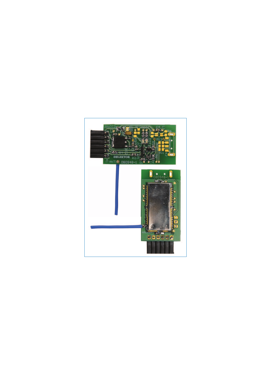
When assembling the PCB, pay
particular attention to the correct
orientation of the Bluetooth mod-
ule. The dot-shaped marking on
the protective cover does not mark
pin 1. The correct orientation of the
BTM-222 module is shown in Fig-
ure 5, with the marking next to the
antenna connection.
Connection to the ATM18 board
The module requires a wire antenna with a
length of 31 mm (a quarter-wave antenna at
2.4 GHz). It must be soldered to the connec-
tion point marked ANT1 on the same side of
the board as the BTM-222 module (see Fig-
ure 5). After this, you can plug the module
board into connector K5 (serial port) of the
ATM18 board (see Figure 6 and the photos)
with the component side facing up (mod-
ule facing down) so you can see the LEDs.
In addition, you must interconnect all three
JP1 pins for supply voltage selection on the
ATM18 board to provide a 5 V supply volt-
age to the Bluetooth board via K5. For test-
ing, you can connect the Bluetooth board
to a PC via a USB to serial interface adapter
cable (such as item number 080313 in the
Elektor Shop) and use a terminal emulator
program to communicate with it. This can
also be helpful if you have accidentally con-
figured the module incorrectly, such as set-
ting a data rate that is not supported by the
ATM18 board.
Tricky communication
One of the shortcomings of the BTM-222
module is that it does not have a buffer for
incoming characters. Consequently, you
always have to wait for each character to
be echoed before sending the next charac-
ter. This means that after you send a com-
mand, you have to wait to see whether the
module sends back ‘OK’ or ‘ERROR’, or
perhaps doesn’t send back anything at all,
and if an error does occur you may have to
repeat the command. This task is handled
by the btm222_sendcmd() function of the
btm222.h/.c software module. The param-
eter is the command, including the trailing
<CR>. The return value is zero only if the
module returns a response of ‘OK’,
which indicates that it has accepted
the command. A timeout ensures
that the function will terminate
even if no response is received from
the module. The construction
while(btm222_sendcmd(<CMD>));
ensures that the program waits until
the module has accepted the com-
mand before proceeding. Defensive
programmers may want to insert an
additional timer to prevent the pro-
gram from hanging here, which is
possible because the command syn-
tax is inherently error-prone.
Software module btm222.h/.c
includes several other routines that
make it easier to use the Bluetooth
module. The btm222_setname()
and btm222_setpin() routines con-
struct the commands necessary to
change the module’s name and PIN
code. The btm222_seek_devices()
function initiates a search for other
Bluetooth devices within range
of the module (including mobile
phones). This search may last up to
one minute. The return value, which
is also entered in btm_n_o_devices,
is the number of devices found.
Their names and IDs can be found
in the btm222_devices field, so you
can use freely configurable names to iden-
tify the other devices and are not forced to
use their ID codes for this purpose. Here it
should be noted that the names in this field
are padded with blanks, so it is better to
use the library function strstr() instead of
strcmp() for comparisons.
You can use the ATA<nr><CR> command
(where nr = 1…8) to establish a connec-
tion to the corresponding device. After a
connection is established, the link acts the
same as an RS232 connection with a cable.
This means that the application program
should evaluate the CONNECT <id> und DIS-
Figure 5. Both sides of the assembled PCB. A length of wire
is soldered to one side to act as an antenna.

66
12-2009 elektor
CONNECT <id> messages sent
by the Bluetooth module to
report link connection and dis-
connection, in order to avoid
having the Bluetooth module
interpret data intended for the
other party as commands.
Before you can utilise these
functions, you have to send
the module an ATR0<CR>
command to make it a master
and an ATO1<CR> command
to disable automatic connec-
tion. However, this is only
possible if no suitable party is
in the vicinity, as otherwise a
connection will be established
immediately.
The module configuration set-
tings are retained after the
supply voltage is removed, so
you have to be careful with
commands that change the
serial interface settings. As you
can see from the ATmega88
data sheet, the standard serial
data rate of 57.6 kbps cannot
be generated with adequate
precision (error
a 1%) with a
16-MHz system clock. If you
configure the BTM-222 mod-
ule for a higher rate, you effec-
tively lock out the ATM18.
The most important commands
are listed in Table 2. The BTM-
222 module data sheet [3] pro-
vides a more extensive list. Vari-
ous undocumented commands
can also be found on the Web,
but they should be used with
considerable caution, or better
yet not at all, as you cannot be
sure that they are supported by
every version of the firmware.
Master and slave
We have programmed a sample
application to illustrate what
you can do with the BTM-222
module. It lets you use up to
four DS1820 sensors (previ-
ously discussed in the ATM18
project article ‘Another Brisk
Day Today’ in the March 2009
issue of Elektor) to measure
temperatures. Pins PD4 to
PD7 are driven as outputs and
can be used to control a heat-
ing system or individual heat-
ers, among other things. This
arrangement could be used to
implement remotely control-
led temperature regulation.
The sequence of the sensors
is determined by their perma-
Table 2. Principal AT commands supported by the BTM-222 module
A
(Establish
connection)
ATA<CR> establishes a connection to the device whose ID was previously set by an ATD=<ID><CR> command.
ATA<no.><CR> establishes a connection to a device previously found in response to an ATF?<CR> command.
D
(Set remote address)
ATD=<ID><CR> specifies the device that the module may connect to. In master mode, a connection can be initiated
after this by issuing an ATA<CR> command. In slave mode, this can be used to prevent an unauthorised master from es-
tablishing a connection. The ATD0<CR> command allows connection to all available devices.
F
(Search for Bluetooth
devices)
ATF?<CR> initiates a search for other accessible devices. The found devices are output in a table. Before a search can be
performed, the module must be put in master mode and autoconnect must be disabled.
N
(Module name)
ATN=<name><CR> sets the name used as the module identifier. The allowed characters are 0–9, a–z, A–Z, blank and
hyphen, but blanks and hyphens are not allowed as initial or final characters of the name. The maximum allowable size
of the name is sixteen characters.
O
(Autoconnect
setting)
Configures a setting that determines whether the module should automatically establish connections with other devi-
ces. ATO0<CR> configures the module to automatically connect to any suitable device that it finds. After an ATO1<CR>
command, each connection must be explicitly initiated by an ATA command.
P
(Set PIN code)
Can be used to change the module’s PIN code. Only modules with the same PIN code can connect to each other. This
enhances security. The factory default PIN code is ‘1234’.
R
(Master/slave)
ATR0<CR> configures the module as a master, while ATR1<CR> configures it as a slave.
Z
(Warm start)
ATZ0<CR> restores the factory default settings.. However, this does not affect all the configuration settings. For instan-
ce, the name remains unchanged.
LCD 20 x 4
+5V
080948 - 13
GND
DA
T
A
CLK
max. 4x
DS1820
4k
7
1
1 = GND
2 = DQ
3 = V
DD
2
2
3
1
3
Figure 6. Several DS1820 temperature sensors can be connected to
the ATM18 board as shown here. The attached Bluetooth module can
transmit the temperature measurements over distances
up to 100 m in free space.
67
elektor 12-2009
nently configured ROM addresses. The sen-
sors are powered ‘parasitically’ via PD3, as
shown by the wiring diagram in Figure 6.
The BTM-222 module is used here as a slave
device. A new, not yet used module is most
likely already configured as a slave, but to
be on the safe side the ATM18 software first
configures the module as a slave. This is nec-
essary because the module retains its con-
figuration settings after the supply voltage
is removed, which means that it will still be
a master if it was previously configured as a
master for testing. As a precaution, the PIN
code is also set to the default value (1234).
If you plug a Bluetooth USB stick into your
PC and run a terminal emulator program on
the PC, you can now establish a connection
to the ATM18 board with the temperature
sensors. It reports its status regularly to its
master by sending the message
S<sensor_number> <temperature1>
<temperature2>...
<outputs><CR><LF>
The temperatures are coded as integers
with a resolution of 0.01 °C. You can use
L<CR> to query the current limits for all of
the sensors, or
L<sensor_number> <lower_limit>
<upper_limit><CR>
to adjust the limits in order to set the
desired temperatures. These limits are also
stored in the EEPROM of the microcontrol-
ler, so they are directly available for use the
next time. If you want to use this arrange-
ment for a project such as monitoring and
controlling temperatures in a greenhouse,
you can add more sensors. Anything you
can imagine, you can do!
Board to board
We also wrote a program to demonstrate a
Bluetooth link between two ATM18 boards.
It displays the status messages of the slave
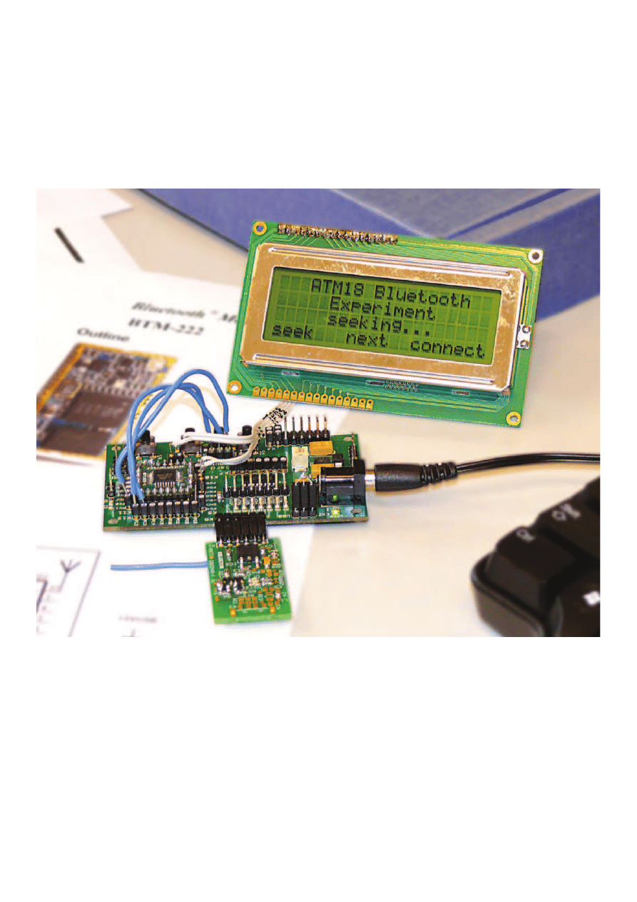
device on the LCD module. This lets you see
the best way to use the BTM-222 module.
The program starts by sending the ‘set mas-
ter’ and ‘disable automatic connection’
commands. They change the default config-
uration of the module as described above,
so that the ATM18 can actively establish a
connection. To ensure that the BTM-222
module is awake and ready for operation,
the program waits until the module has
accepted these commands.
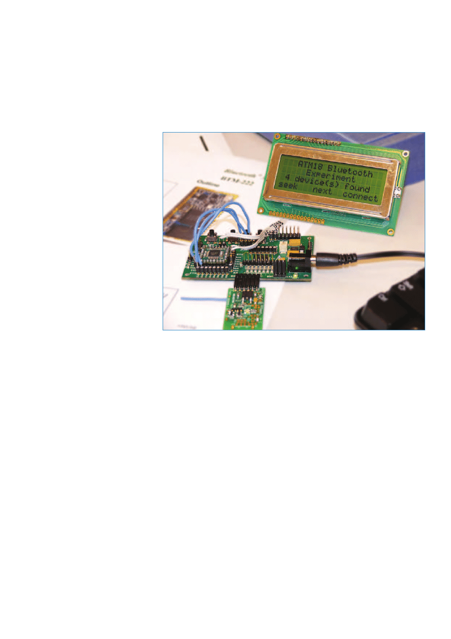
The operation of the program is control-
led by three buttons (S1, S2 and S3) on
the ATM18 board. Via K8, S1 is connected
to PC1, S2 to PC2, and S3 to PC3. Pressing
S1 starts a search for all available Bluetooth
devices in the vicinity. After the search is
completed, you can press S2 to display the
names and IDs of the located devices (see
Figure 7). By default, a BTM-222 module is
shown as ‘Serial Adaptor’.
Press S3 to establish a connection, after
which the temperatures measured by the
individual sensors and the states of the cor-
responding outputs will be displayed.
Downloads
The source text of the two programs has
been written for use with the free GCC AV
cross-compiler, which is available for many
platforms. The software can be downloaded
free of charge from the Elektor web page
for the ATM18 Bluetooth project (www.
elektor.com/080948). The PCB layout of
the Bluetooth board is also available on
the same page for free download. A list of
all previously published articles on the CC2
ATM18 system is available at www.elektor.
com/071137. On the Elektor forum every-
one’s invited to discuss the projects and
articles published so far in the ATM18 / CC2
article series, as well as the closely related
BASCOM AVR Course – see www.elektor.
com/forum.
(080948-I)
References and Links
[1] www.elektor.com/080852
[2] ‘Bluetooth: 2.4-GHz Data Radio instead
of Computer Cables’,
Elektor January 2000
[3] www.elektor.com/080948
Figure 7. In each search cycle, the ATM18 board with attached Bluetooth module
detects every Bluetooth device in its vicinity.
Wyszukiwarka
Podobne podstrony:
Magiczne przygody kubusia puchatka 22 THE WOMEN ARE HOT!
KasparovChess PDF Articles, Sergey Shipov The Stars of the Orient Are the Brightest Ones!
The World of the Vikings
Timbaland The Way I Are
Latvia in the Viking Age
The?ad Are With Us
US5 the boys are?ck
Lecture 4 The Vikings
j.angielski, MEL INSIDE, The other(s) = the rest `Only those books are mine; the others are f
ATM18 On the Air
Nanocosm Nanotechnology and the Big Changes Coming from the Inconceivably Small, 2005, p 320
The Vikings and the Clothes they Wore
Magiczne przygody kubusia puchatka 22 THE WOMEN ARE HOT!
KasparovChess PDF Articles, Sergey Shipov The Stars of the Orient Are the Brightest Ones!
Melanie Thornton Wonderful Dream (Holidays are coming
Dixon, Franklin W Hardy Boys 042 The Viking Symbol Mystery
The Tough Get Coming
Theodore Sturgeon The Stars are the Styx
the cows are amilking
więcej podobnych podstron