
Initial Print Date: 01/09
Table of Contents
Subject
Page
Input/Output - Comfort Access . . . . . . . . . . . . . . . . . . . . . . . . . . . . . . . .6
System Circuit Diagram - Comfort Access . . . . . . . . . . . . . . . . . . . . . . . . .8
Remote Control Function for Comfort Access . . . . . . . . . . . . . . . . . .10
Passive Entry at the Trunk . . . . . . . . . . . . . . . . . . . . . . . . . . . . . . . . . . .12
Special Comfort Access Functions . . . . . . . . . . . . . . . . . . . . . . . . . . . . .16
Second ID Transmitter Remains in the Vehicle Interior . . . . . . . . . .16
Identification Transmitter in Luggage Compartment . . . . . . . . . . . .16
Starting the Engine without an ID Transmitter . . . . . . . . . . . . . . . . . .16
Unintentional Wake-up Function . . . . . . . . . . . . . . . . . . . . . . . . . . . . .17
Locking with Engine Running . . . . . . . . . . . . . . . . . . . . . . . . . . . . . . . .17
Emergency Start Coil . . . . . . . . . . . . . . . . . . . . . . . . . . . . . . . . . . . . . . .17
Data for Conditioned Based Service . . . . . . . . . . . . . . . . . . . . . . . . . .20
Antennas for Comfort Access . . . . . . . . . . . . . . . . . . . . . . . . . . . . . . . . . .20
Antenna Installation Locations . . . . . . . . . . . . . . . . . . . . . . . . . . . . . . .20
Exterior antennas . . . . . . . . . . . . . . . . . . . . . . . . . . . . . . . . . . . . . . . .20
Interior antennas . . . . . . . . . . . . . . . . . . . . . . . . . . . . . . . . . . . . . . . .20
Luggage compartment antenna . . . . . . . . . . . . . . . . . . . . . . . . . . .21
Outside Door Handle Electronics Module . . . . . . . . . . . . . . . . . . . . . . . .22
F01 Comfort Access
Revision Date:

Subject
Page
Capacitive sensor 1 . . . . . . . . . . . . . . . . . . . . . . . . . . . . . . . . . . . . .22
Capacitive sensor 2/piezo sensor . . . . . . . . . . . . . . . . . . . . . . . . . .22
Outside door handle Hall sensor . . . . . . . . . . . . . . . . . . . . . . . . . .23

Subject
Page
BLANK
PAGE

4
F01 Comfort Access
Comfort Access
Model: F01/F02
Production: From Start of Production
After completion of this module you will be able to:
• Understand the functions of Comfort Access on the F01/F02
• Understand the “Passive Go” functions on the F01/F02

Keyless Vehicle Access
Using Comfort Access, the customer can unlock and open the vehicle without active use
of the ID transmitter. Access to the vehicle can be gained from any point. It is important
that the ID transmitter be located in the vehicle’s immediate vicinity (approximately 5
feet). It is sufficient to have the ID transmitter somewhere on your person.
Comfort Access was first introduced on the E65 (03/2002). The system was then gradu-
ally introduced on different BMW models. There were the 1 Series, 3 Series, 5 Series,
6 Series, X5 and X6.
The F01/F02 will have Comfort Access from the start of series production in 09/2008.
Comfort Access can be ordered as an option.
The benefits of Comfort Access are:
• High level of convenience when unlocking and locking the vehicle
• Convenient and fast access to the vehicle
• Simple engine start/stop procedure
• Maximum comfort for the driver
• No more annoying hunting for keys.
The Comfort Access in the F01/F02 is based on predecessor systems and is adapted to
the F01/F02. However, the entire function is now located in the Car Access System 4.
For this reason, there is no separate control unit for Comfort Access in the F01/F02, in
contrast to previous systems.
The vehicle is unlocked when you place your hand into the handle recess on the outside
of the door and opened when you pull the door handle.
You can lock the vehicle again by subsequently pressing on the sensitive surface of the
outside door handle.
For vehicles fitted with Soft Close Automatic, the Soft Close Automatic drive fully closes
the vehicle door. You can then lock the vehicle again by subsequently pressing on the
sensitive surface of the outside door handle.
The ID transmitter must be located in the vehicle interior in order for the engine to be
started. The engine can now be started by pressing the START-STOP button and the
vehicle is ready to be driven.
Note: In vehicles with automatic transmission, the brake pedal must be
depressed in order for the engine to be started.
In vehicles with manual transmission, the clutch pedal must be
depressed in order for the engine to be started.
5
F01 Comfort Access
Introduction

System Overview
Input/Output - Comfort Access
6
F01 Comfort Access
Index
Explanation
Index
Explanation
1
CAS 4 Car Access System 4
8
START-STOP button
2
Footwell module (FRM)
9
Antenna for Comfort Access
3
Junction box electronics (JB)
10
Outside door handle electronics module
4
Emergency start coil (transponder coil)
11
Lock with door contact
5
Central locking button
12
Driver's door lock cylinder
6
ID transmitter
CA
Comfort Access (function)
7
Diversity module
K-CAN2
Body CAN2

7
F01 Comfort Access
NOTES
PAGE

System Circuit Diagram - Comfort Access
8
F01 Comfort Access

9
F01 Comfort Access
Index
Explanation
Index
Explanation
1
Footwell module (FRM)
14
Luggage compartment lighting
2
Junction box electronics (JB)
15
Interior antenna for Comfort Access, parcel shelf
3
Front distribution box
16
Luggage-compartment antenna, driver’s side
4
Lock door contact, front-passenger side,
front
17
Rear driver’s side outside door handle electronics
5
Outside door handle electronics,
front-passenger side, front
18
Lock door contact, driver’s side, rear
6
Antenna for Comfort Access, door sill,
front-passenger side
19
Antenna for Comfort Access, door sill,
driver’s side
7
Lock door contact, front-passenger side,
rear
20
Outside door handle electronics, driver’s side,
front
8
Outside door handle electronics,
front-passenger side, rear
21
Lock door contact, driver’s side,
front and locking cylinder in driver’s door
9
Luggage-compartment distribution box
22
Car Access System 4 (CAS 4) with
Comfort Access (CA) function
10
Luggage-compartment antenna,
front-passenger side
23
Antenna for Comfort Access, interior, front
11
Central locking button
24
Antenna for Comfort Access, interior, rear
12
Antenna for Comfort Access, bumper
K-CAN2
Body CAN2
13
Trunk lock

Function Overview
Comfort Access is divided into the following functions:
• Passive Entry
• Passive Go
• Passive Exit.
ID transmitters are required for Comfort Access to function.
An ID transmitter comprizes, among other things:
• A battery
• Remote control function
• Transponder coil for emergency start function
• Mechanical key
• Receiver unit.
Remote Control Function for Comfort Access
When the unlocking or locking button on the ID transmitter is pressed, it emits an
encrypted remote control signal. The antenna in the rear window forwards the remote
control signal to the diversity module. The diversity-module remote control receiver
demodulates, processes and then sends the signal to the Car Access System on the
LIN bus.
If the vehicle is in sleep mode, the remote control receiver wakes the Car Access
System to reduced consumption mode via the LIN bus. The Car Access System thus
receives the request that was sent using the ID transmitter. The ID transmitter is
checked by the remote control receiver at this stage. If the result of the check is positive,
the remote control receiver forwards the request via the LIN bus. If the request is
authenticated, the Car Access System wakes the vehicle and initiates the unlocking or
locking of the vehicle. To do so, the Car Access System issues the release signal for the
junction box electronics to actuate the central-locking drive.
The ID transmitter can also be used to open the trunk separately. For this, only the
button with the open trunk symbol need be pressed.
The Car Access System is responsible for communication via the LIN bus. The diversity
module therefore only forwards the LIN bus signal if prompted to do so by the Car
Access System 4. This applies to a vehicle that is not in sleep mode.
10
F01 Comfort Access
Functions
Passive Entry
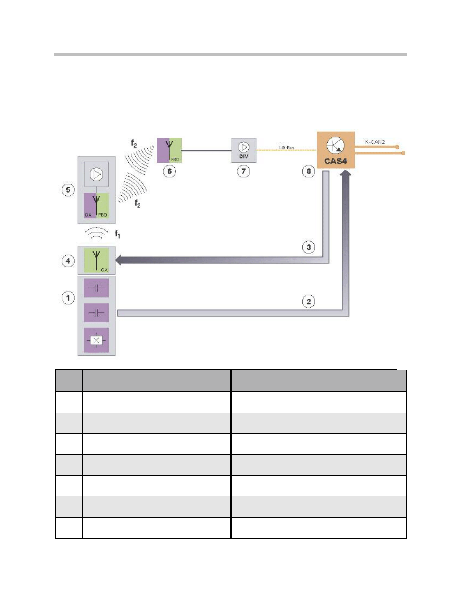
The graphic below shows the functional principle of “Passive Entry”.
11
F01 Comfort Access
Index
Explanation
Index
Explanation
1
Outside door handle electronics module (TAGE)
8
Car Access System 4 (CAS 4)
2
TAGE request to the CAS
LIN-Bus
Local Interconnect Network bus
3
Prompt about Comfort Access antenna
f
1
Low frequency in the kHz range
4
Comfort Access antenna
f
2
High frequency in the MHz range
5
ID transmitter
K-CAN2
Body CAN2
6
Rear window antenna
CA/FBD
Comfort Access/remote control services
7
Remote control receiver in the diversity module
Signal path for Comfort Access in the F01/F02 Passive Entry System

Passive Entry enables access to the vehicle without the ID transmitter being actively
operated.
For example, if the outside door handle is pulled, this triggers a pulse in the sensor.
The outside door handle electronics analyze the sensor and inform the Car Access
System that vehicle access is requested.
The Car Access System prompts the ID transmitter to identify report to the vehicle.
For this, a low-frequency signal is emitted by Comfort Access via the antennas.
Transmission is via the 125 kHz antennas.
The 125-kHz signal serves only to wake the ID transmitter. The ID transmitter responds
with its transmission frequency. Subsequent communication is now bi-directional, i.e. in
two directions. The Car Access System sends or receives all further information via the
LIN bus.
The remote control receiver is equipped with both a receiver unit and a transmitter unit.
It establishes the connection with the ID transmitter via the rear-window antenna. For that
reason, only the high frequency range is now used.
Bi-directional communication has the advantage that data can be requested from or sent
to the ID transmitter. The Car Access System has sole responsibility for this communica-
tion.
If the ID transmitter is able to be authenticated, the Car Access System initiate the
request, e.g. unlocking the vehicle. The junction box electronics execute the unlocking.
The transmission frequency of the ID transmitter varies for the US is 315MHz.
Note: When it is not required, the ID transmitter is in sleep mode. This reduces
its energy consumption. For sleep mode to be ended, the ID transmitter
requires a wake-up signal. The wake-up signal can be sent by the Car
Access System via the Comfort Access antennas. Pressing one of the
buttons on the ID transmitter also wakes it.
Passive Entry at the Trunk
An authentication check also takes place before the trunk is opened.
If the outside trunk button in the trunk handle strip is operated, it changes its status.
The junction box electronics analyze the status and send it via the K-CAN2.
The Car Access System 4 therefore knows that the outside trunk button has been oper-
ated.
The Car Access System initiates the emission of the 125 kHz signal, so that the ID trans-
mitter can report to the vehicle.
At the same time, the Car Access System initiates communication to the ID transmitter.
12
F01 Comfort Access

The Car Access System sends the requests for this via the LIN bus to the remote control
receiver. The latter sends the requests from the Car Access System via the rear-window
antenna.
If the ID transmitter is recognized as belonging to the vehicle, the Car Access System
prompts the junction box electronics to unlock the trunk.
13
F01 Comfort Access
Index
Explanation
Index
Explanation
1
Outside trunk button in the handle strip
of the luggage compartment lid
8
Remote control receiver in the diversity module
2
Junction box electronics (JB)
LIN-Bus
Local Interconnect Network bus
3
Car Access System 4 (CAS 4)
K-CAN2
Body CAN2
4
CAS request to the CA antenna
f
1
Low frequency in the kHz range
5
Bumper antenna for Comfort Access
f
2
High frequency in the MHz range
6
ID transmitter
CA/FBD
Comfort Access/remote control services
7
Rear window antenna
Principle of Comfort Access at the trunk

Passive Go
The “Passive Go” function makes it possible to start the vehicle when the ID transmitter is
in the passenger compartment.
Issuing Start Enable
Authorization to start the engine is only given when there is an ID transmitter in the vehi-
cle. Once the last door is closed, the Car Access System begins its search for a valid ID
transmitter.
The Car Access System 4 requests a signal to be sent out to identify a valid ID transmit-
ter. The interior antennas are used for this.
The ID transmitter responds using a high-frequency range (315 MHz). If the ID transmit-
ter is authenticated, the Car Access System 4 grants permission for the engine to be
started.
Note: The electronic immobilizer gives its own approval for the engine to be
started.
The search for an ID transmitter in the passenger compartment can also be triggered
by pressing the START-STOP button. This will take place if the START-STOP button is
pressed before the last door is closed, for instance.
Or if the vehicle is stationary too long and therefore loses communication with the ID
transmitter. Pressing the START-STOP button triggers the search for the ID transmitter
in the vehicle interior.
14
F01 Comfort Access

Passive Exit
The Passive Exit function makes it possible to lock the vehicle without actively using the
ID transmitter.
Locking Procedure
After the vehicle door has been closed, the locking procedure is started by pressing the
sensitive area on the outside door handle. The outside door handle electronics module
sends the request to unlock the vehicle to the Car Access System 4.
The Car Access System 4 checks whether a valid ID transmitter is in the vicinity of the
outside door handle using the outside antennas.
The ID transmitter is instructed to send an authentication signal.
In turn, the identification sensor sends encrypted data via the high-frequency link to the
remote control receiver.
The remote control receiver processes the data and sends it via the LIN bus to the Car
Access System. The Car Access System causes the communication with the ID trans-
mitter to be established.
If the ID transmitter is recognized as belonging to the vehicle, the Car Access System 4
issues authorization for the vehicle to be unlocked.
The junction box electronics activate the central-locking drives.
15
F01 Comfort Access

Special Comfort Access Functions
The Comfort Access additionally features the special functions described in the following
that are determined by the actions of the vehicle user.
Second ID Transmitter Remains in the Vehicle Interior
By checking via the interior antennas, the Car Access System 4 recognizes whether there
is a valid ID transmitter in the vehicle interior. If the Car Access System 4 detects a valid
ID transmitter in the vehicle interior and the vehicle is locked by means of another valid ID
transmitter (located outside), the ID transmitter located in the vehicle interior is set to
"blocked".
This ID transmitter will not be recognized as belonging to the vehicle for Comfort Access
until the vehicle is unlocked again.
Note: The "blocked" status only applies to the functions of Comfort Access.
The remote control functions are still available.
Identification Transmitter in Luggage Compartment
If an ID transmitter is located in the luggage compartment when the vehicle is locked and
the trunk open and the trunk is then closed, the trunk will immediately be automatically
opened again. Audible and visual signals draw the customer's attention to the fact that
the ID transmitter is located in the luggage compartment.
The Car Access System 4 starts the request via the luggage-compartment antennas.
If a valid ID transmitter is detected in the luggage compartment, the Car Access System
4 will not issue authorization for the trunk to be locked.
The trunk cannot be closed before the ID transmitter has been removed and is located
outside the luggage compartment.
Note: This behavior only occurs if the Comfort Access does not find a valid ID
transmitter in the vicinity of the vehicle when it searches the outside of
the vehicle.
Starting the Engine without an ID Transmitter
This function makes it possible to start the vehicle within 10 seconds after “engine OFF”
without detecting the ID transmitter. This function is intended for cases where, for exam-
ple, the ID transmitter is not detected due to high-frequency interference.
16
F01 Comfort Access
Unintentional Wake-up Function
The vehicle cannot be woken simply by someone gripping the outside door handle. A
valid ID transmitter must be detected in the vicinity of the vehicle.
Locking with Engine Running
The vehicle can also be unlocked with the engine running if the engine was started with
Passive Go. When leaving the vehicle, the ID transmitter should also be taken and the
vehicle locked from the outside.
Emergency Start Coil
In unfavorable situations, the ID transmitter cannot be found in the passenger compart-
ment. The Car Access System therefore causes a message to be output to the instru-
ment cluster. The message tells the customer that the ID transmitter could not be found.
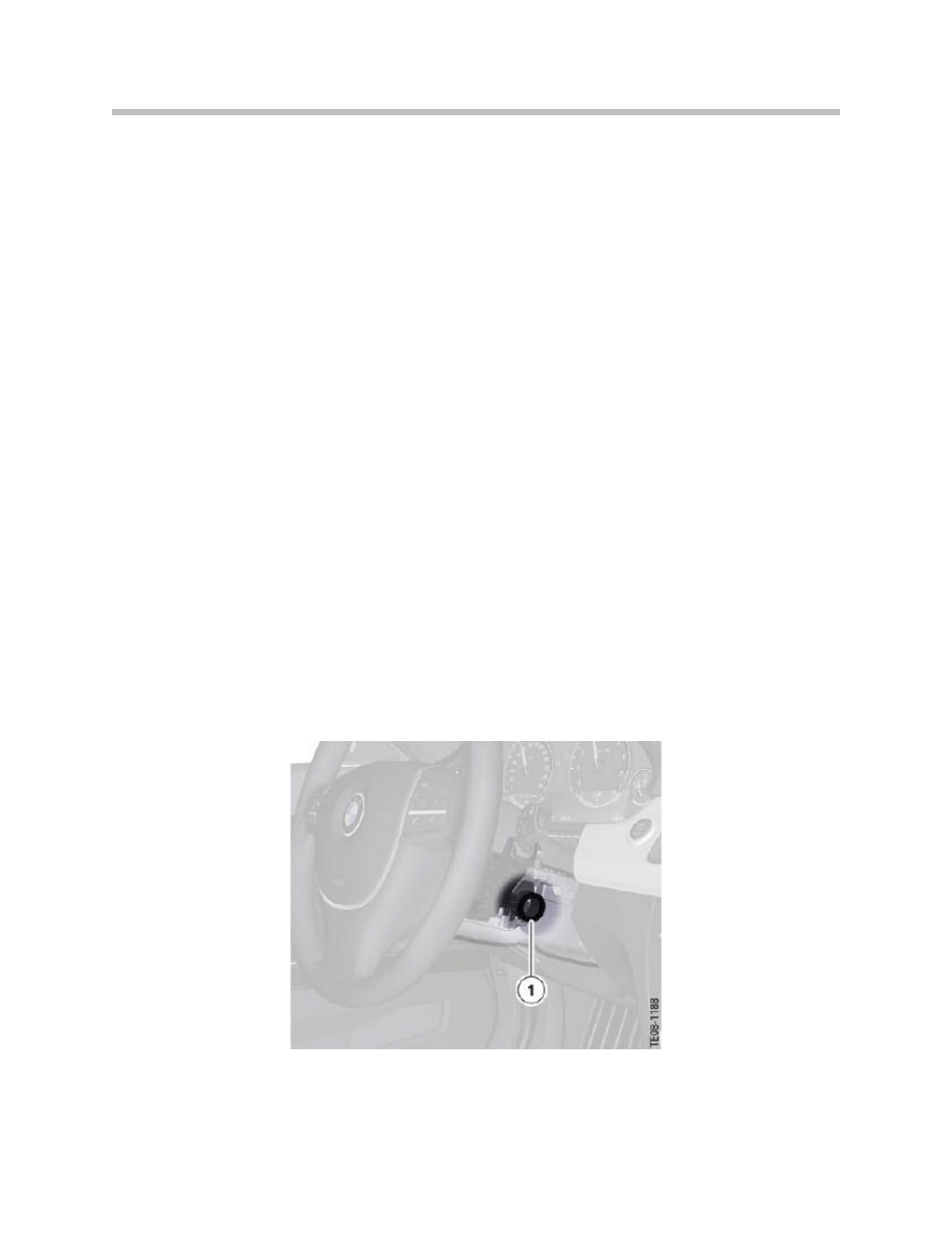
Because there is no slot for the ID transmitter in the F01/F02, there is an emergency start
coil on the steering column. Communication via the emergency start coil allows the
engine to be started and the vehicle is then ready to be driven.
The emergency start coil has the same function as the transponder coil. Communication
via the transponder coil makes it possible for the Car Access System 4 to identify the ID
transmitter. The Car Access System 4 can issue the start authorization following success-
ful identification.
The remote control or ID transmitter cannot be found in the following situations:
• Fault in the remote control/ID transmitter
• Interference in the transmission to the remote control/ID transmitter
• Flat battery in the remote control/ID transmitter.
17
F01 Comfort Access
Emergency start coil
Control Unit
The Car Access System is located above the steering column on the right-hand side.
For the Comfort Access function, the Car Access System controls the transmitting
antennas for the vehicle exterior and interior.
The outside door handle electronics are read by the Car Access System.
18
F01 Comfort Access
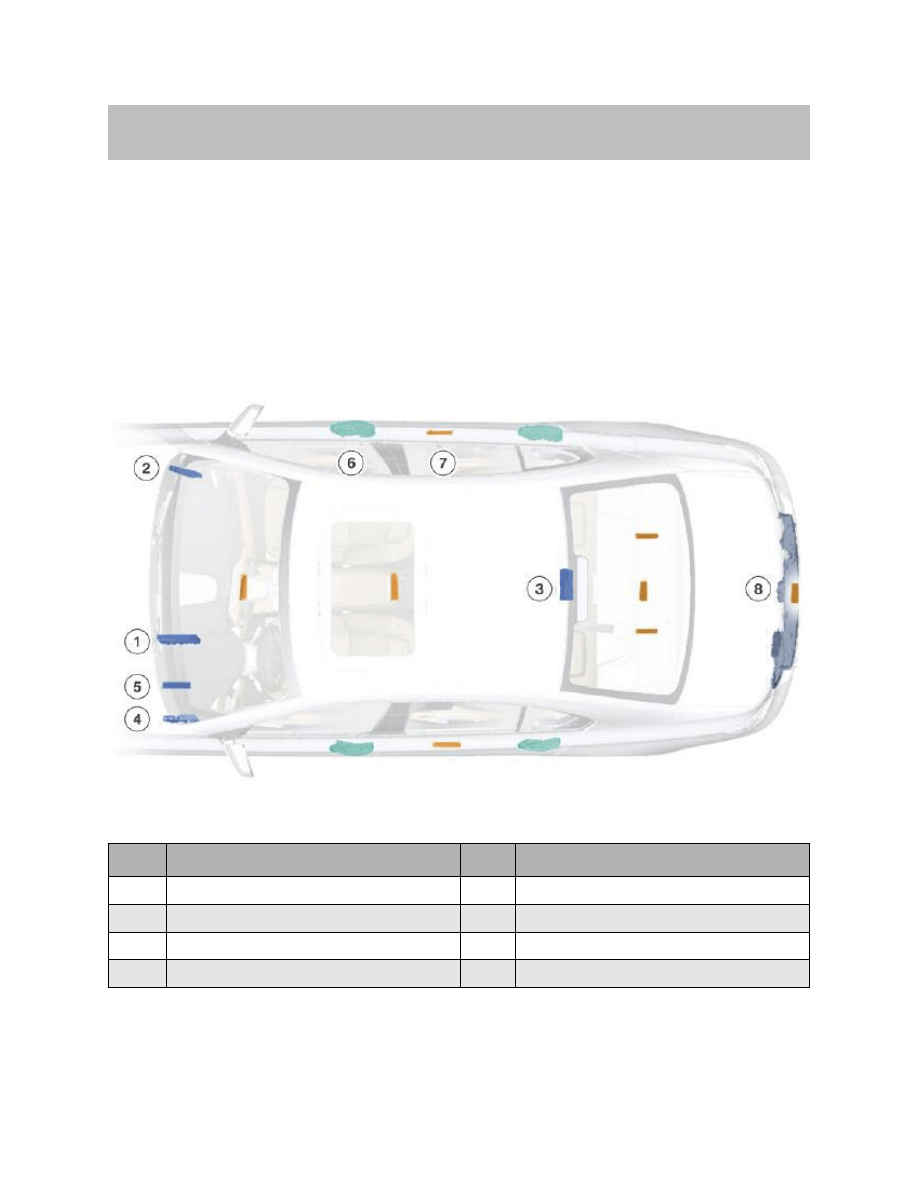
System Components
Index
Explanation
Index
Explanation
1
Car Access System 4 with Comfort Access
5
Central gateway module
2
Junction box electronics
6
Outside door handle electronics
3
Remote control receiver in the diversity module
7
Antennas for Comfort Access
4
Footwell module
8
Central locking components in the trunk
Installation location of the Car Access System 4 with Comfort Access
Control Elements
ID Transmitter
The ID transmitter for Comfort Access must be actuated by means of a radio signal.
The ID transmitter is therefore equipped with a receiver for the coded 125 kHz radio
signal that is transmitted by the Comfort Access antennas. The radio signal wakes the ID
transmitter. The ID transmitter registers with the vehicle automatically (authentication).
For this purpose, the ID transmitter emits a coded 315 MHz high-frequency signal to
enable identification of the ID transmitter as being valid and belonging to the vehicle.
The ID transmitter is exclusively responsible for use of the Comfort Access system.
The ID transmitter has a battery, the service life of the battery in the ID transmitter is
about 4 years.
Voltage Monitoring
The ID transmitter monitors its own battery voltage. The battery voltage is monitored in 2
stages.
The first stage signals to the Car Access System 4 that the battery is flat. In response, the
Car Access System 4 generates a check control message. The check control message
informs the customer that the battery needs to be changed.
If the battery is not changed, the voltage monitoring facility switches to the second stage.
This means that the data in the ID transmitter is saved. The ID transmitter is then set to
“inoperative”.
19
F01 Comfort Access
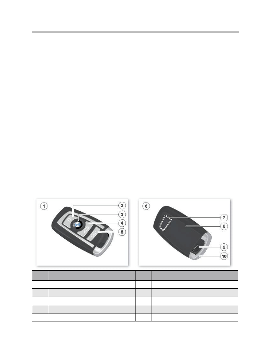
Index
Explanation
Index
Explanation
1
Top view of ID transmitter
6
Rear view of ID transmitter
2
Vehicle unlock button
7
Transponder coil
3
Vehicle lock button
8
Battery compartment
4
Trunk unlock button
9
Mechanical key button
5
Follow-me-home lights button
10
Mechanical key
F01/F02 ID transmitter

Data for Conditioned Based Service
From terminal status “terminal 15 ON”, data for the Conditioned Based Service is trans-
ferred to the ID transmitter in the high-frequency range. The ID transmitter then confirms
that the transmission was received.
Antennas for Comfort Access
Eight antennas are installed for the Comfort Access system. Five antennas are for the
vehicle interior and three are for the vehicle exterior.
The antennas for the exterior and interior are inductive antennas and have a ferrite core.
The antenna transmission frequency is 125 kHz . All messages that are sent via the
antennas are encrypted.
Antenna Installation Locations
Exterior antennas
The exterior antennas are installed in the following locations on the F01/F02:
• Door sill on the driver’s side, in the center of the vehicle
• Door sill on the front-passenger side, in the center of the vehicle
• Rear bumper in the center
The antennas are designed to give about 5 feet (1.5 m) of coverage around the vehicle.
The exterior antennas are equipped with a splash-proof plug connection.
Interior antennas
The interior antennas are installed in the following locations in the F01/F02:
• Passenger compartment, front center console
• Passenger compartment, middle center console
• Luggage compartment, left and right
• Parcel shelf
20
F01 Comfort Access
Passenger-compartment antenna in the door sills in the F01/F02

The antenna characteristic is spherical. The entire vehicle interior is covered by the front
and middle antennas.
Luggage compartment antenna
The luggage-compartment antennas are of the same design as the interior antennas.
They are integrated in the left- and right-hand sides of the luggage compartment.
The luggage-compartment antennas are configured so that they cover the entire luggage
compartment.
21
F01 Comfort Access
Front passenger-compartment antenna in the F01/F02

Outside Door Handle Electronics Module
The outside door handle electronics are connected to terminal 30F and work within a
voltage range of 9 V to 16 V. The Car Access System is directly connected to the data
line of the outside door handle electronics. This provides the Car Access System with
information about the capacitive sensors and the piezo sensors. The status of the “pull”
Hall sensor is monitored directly by the Car Access System.
The outside door handle electronics detect the status of the outside door handle using
the sensors.
Each change in the status of the outside door handle module triggers the corresponding
function.
These functions are:
• Trigger pulse by inserting a hand into the handle recess of the outside door handle;
Capacitive sensor 1
• Unlock request by pulling the outside door handle; Hall sensor
• Lock request by pressing the sensitive area on the outside door handle; capacitive
sensor 2 plus piezo sensor.
Sensors
Capacitive sensor 1
If a hand is placed into the handle recess of the outside door handle, for example, this is
detected by the outside door handle electronics. On detecting this, the outside door han-
dle electronics send the request to the Car Access System. The request initially contains
the information to wake up the Car Access System. The Car Access System is woken
and reads the request. Then, the Car Access System establishes communication with the
ID transmitter.
The Car Access System switches the remote control receiver on permanently and there-
fore ensures that the data sent by the ID transmitter can be received.
Note: The remote control receiver is integrated in the diversity module.
Capacitive sensor 2/piezo sensor
Touching the sensitive surface generates the capacitive sensor 2 signal. Together with
the piezo sensor, a press on the sensitive surface is detected. A lock signal is only trig-
gered if the capacitive sensor and piezo sensor are both actuated.
The outside door handle electronics analyze the two sensors and send the request to the
Car Access System.
22
F01 Comfort Access

Outside door handle Hall sensor
The Hall sensor is redundant to the capacitive sensor 1. The Hall sensor is analyzed
directly by the Car Access System. The Car Access System monitors the Hall sensor
using a clocked voltage supply.
If the vehicle has already been woken by someone reaching into the handle recess,
pulling on the outside door handle triggers the unlocking on the vehicle.
In unfavorable situations, it may be necessary to pull on the outside door handle twice to
trigger the vehicle unlocking. This is caused if the signal from the capacitive sensor 1 is
not present or is implausible.
Door Locks
The vehicle has rapid opening locks in the doors as standard. A spring exerts pretension
on the central locking drive for the unlocking procedure. The door is already unlocked
before an attempt is made to open it with the outside door handle.
Note: However, if the outside door handle is pulled very fast, the vehicle door
may not yet be unlocked. In this case, it is necessary to pull the outside
door handle a second time in order to open the door.
23
F01 Comfort Access
Document Outline
- Main Menu
- 01_F01 Introduction
- 02_F01 Powertrain
- 03_F01 Voltage Supply & Bus Systems
- 03.1_F01 Bus Systems
- 03.2_F01 Voltage Supply
- 03.3_F01 Energy Management
- 03.4_F01 Car Access System 4
- 04_F01 Chassis Dynamics
- 04.1_F01 Chassis and Suspension
- 04.2_F01 Dynamic Driving Systems
- 04.3_F01 Longitudinal Dynamics Systems
- 04.4_F01 Lateral Dynamics Systems
- 04.5_F01 Vertical Dynamics Systems
- 04.6_F01 Cruise Control Systems
- 05_F01 General Vehicle Electronics
- 05.1_F01 Comfort Access
- 05.2_F01 Central Locking System
- 05.3_F01 Automatic Soft Close
- 05.4_F01 Power Windows
- 05.5_F01 Sliding Tilting Sunroof
- 05.6_F01 Anti-theft System
- 05.7_F01 Automatic Luggage Compartment Lid
- 05.8_F01 Exterior Lighting
- 05.9_F01 Interior Lighting
- 05.10_F01 Wiper-Washer System
- 05.11_F01 Exterior Rear View Mirrors
- 05.12_F01 Seats
- 05.13_F01 Steering Column Switch Cluster
- 06_F01 Driver Information Systems
- 06.1_F01 Displays Indicators and Controls
- 06.2_F01 Head-up Display
- 06.3_F01 BMW Night Vision 2
- 06.4_F01 Active Blind Spot Detection System
- 06.5_F01 KAFAS
- 06.6_F01 PDC-TRSVC
- 07_F01 Information and Communication Technology
- 07.1_F01 Rear Seat Entertainment Systems
- 07.2_F01 Telephone System
- 07.3_F01 Voice Activation System
- 07.4_F01 Audio Systems
- 08_F01 Climate Control
- 09_F01 Passive Safety Systems
- 10_F01 Service Information
- 10.1_F01 System Functions
- 10.2_ISTA-Programming
Wyszukiwarka
Podobne podstrony:
05 E65 Car Access System
05a3 E70 Comfort Access
05 6 F01 Anti theft System
05 4 F01 Power Windows
06 E65 66 Comfort Access
2009 05 Fine Grained Access Control
05 8 F01 Exterior Lighting
05 7 F01 Automatic Luggage Compartment Lid
05 9 F01 Interior Lighting
05 2 F01 Central Locking System
05 5 F01 Sliding Tilting Sunroof
05 3 F01 Automatic Soft Close
05. Access - zadania, Bazy danych-materiały, Acces
05 Praktyczne wskazówki do programu Access
05 10 F01 Wiper Washer System
05 13 F01 Steering Column Switch Cluster
05 11 F01 Exterior Rear View Mirrors
05 12 F01 Seats
więcej podobnych podstron