
Initial Print Date: 10/06
Table of Contents
Subject
Page
Input/Output . . . . . . . . . . . . . . . . . . . . . . . . . . . . . . . . . . . . . . . . . . . . . . . . . . .5
System Circuit Diagram . . . . . . . . . . . . . . . . . . . . . . . . . . . . . . . . . . . . . . . . .6
Control Unit . . . . . . . . . . . . . . . . . . . . . . . . . . . . . . . . . . . . . . . . . . . . . . . . . . . .8
Control Elements . . . . . . . . . . . . . . . . . . . . . . . . . . . . . . . . . . . . . . . . . . . . . . .9
Antennas for Comfort Access . . . . . . . . . . . . . . . . . . . . . . . . . . . . . . . . . . .10
Antenna Installation Locations . . . . . . . . . . . . . . . . . . . . . . . . . . . . . . . .10
Outside Door Handle Electronics Module . . . . . . . . . . . . . . . . . . . . . . . .11
Signal Path for Comfort Access . . . . . . . . . . . . . . . . . . . . . . . . . . . . . . .14
Unlocking Sequence . . . . . . . . . . . . . . . . . . . . . . . . . . . . . . . . . . . . . . . .15
Passive Entry for Upper Tailgate . . . . . . . . . . . . . . . . . . . . . . . . . . . . . .15
E70 Comfort Access
Revision Date:

Subject
Page
Two ID transmitters Remain Inside the Vehicle . . . . . . . . . . . . . . . . .17
The ID Transmitter Inside the Luggage Compartment . . . . . . . . . . .17
Starting Engine without ID Transmitter . . . . . . . . . . . . . . . . . . . . . . . .17
Check Control Message, Terminal 15 . . . . . . . . . . . . . . . . . . . . . . . . .18
Unintentional Wake-up Function . . . . . . . . . . . . . . . . . . . . . . . . . . . . . .18
Locking with Engine Running . . . . . . . . . . . . . . . . . . . . . . . . . . . . . .18

3
E70 Comfort Access
Comfort Access
Model: E70
Production: From Start of Production
After completion of this module you will be able to:
• Explain the Comfort Access system in the E70 X5
• Locate all the components used in the system

4
E70 Comfort Access
Using Comfort Access the customer can unlock and open the vehicle without active use
of the ID transmitter. It is unimportant how the customer wishes to access the vehicle. It
is important that the ID transmitter be located in the vehicle's immediate vicinity (approxi-
mately. 2m). It is sufficient to have the ID transmitter somewhere on your person.
Comfort Access was first introduced on the E65 (03/2002). The system was then gradu-
ally introduced on different BMW models.
These models are:
• E87 from 09/2004
• E90 from 03/2005
• E60 from 09/2005
• E61 from 09/2005
• E63 from 09/2005
• E64 from 09/2005
• E91 from 09/2005
• E92 from 05/2006.
Comfort Access is available on the E70 from SOP (Start of Production).
The benefits of Comfort Access are:
• High level of convenience when unlocking and locking the vehicle
• Quick and easy access to the vehicle
• Easy engine start/shutdown
• Maximum comfort for the driver
• No more annoying hunting for keys.
The system is based on the Comfort Access on the E90/E91. Inserting a hand into the
handle recess of the outside door handle unlocks and then opens the vehicle. The vehi-
cle is locked by touching the sensitive area of the outside door handle.
For vehicles fitted with Soft Close Automatic, the Soft Close Automatic drive fully closes
the vehicle door. The sensitive area can then be used to lock the vehicle.
To allow the engine to start, an ID transmitter must be located in the vehicle interior. This
being the case, when the START-STOP button is pressed, the engine starts and the
vehicle is ready for use.
Introduction
Input/Output
5
E70 Comfort Access
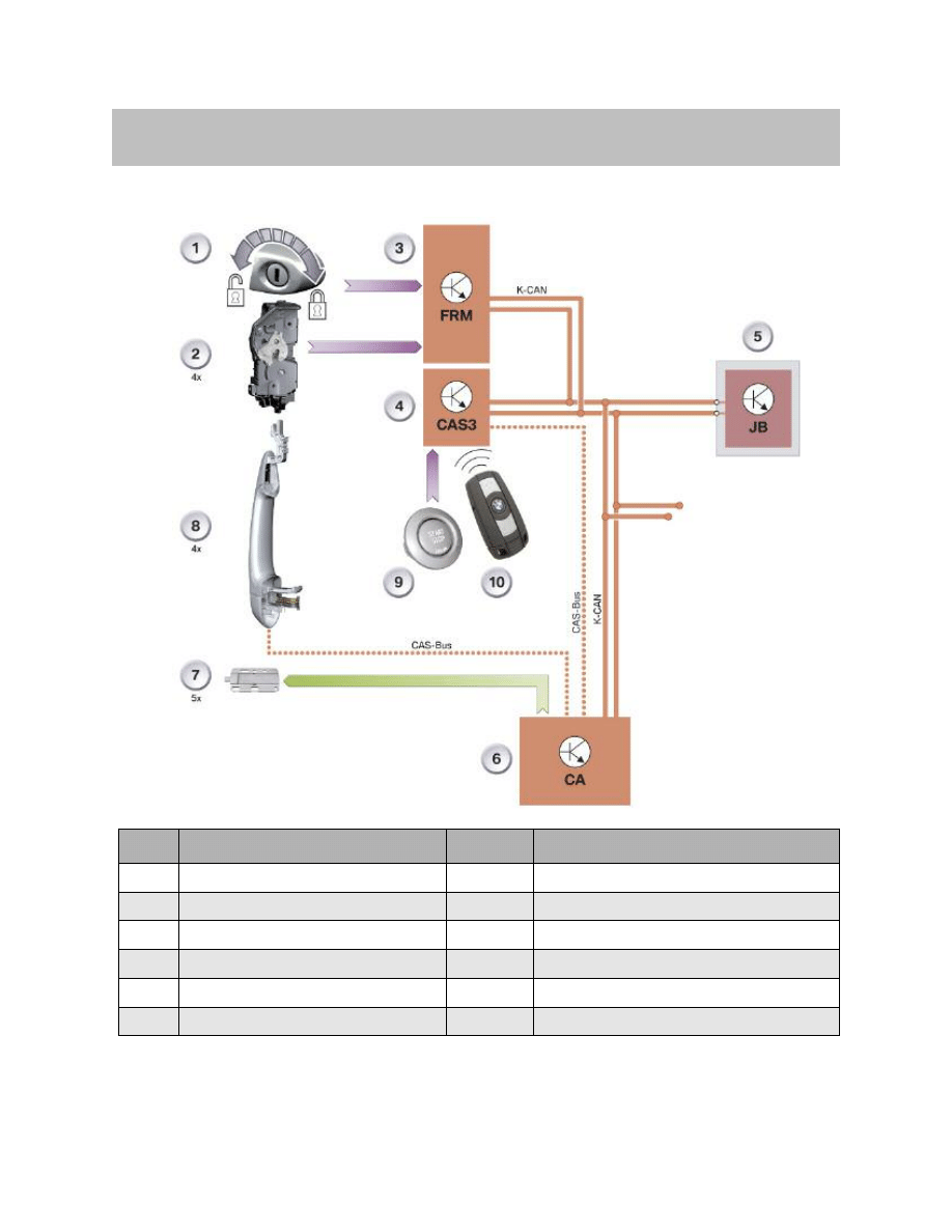
System Overview
Index
Explanation
Index
Explanation
1
Driver's door lock cylinder
7
Interior antenna x 5
2
Lock with door contact x 4
8
Outside door handle electronics module
3
Footwell module FRM
9
START-STOP button
4
Car Access System 3 CAS 3
10
ID transmitter
5
Junction box control unit JB
K-CAN
Body CAN
6
Comfort access CA
CAS-Bus
CAS-bus (K-bus protocol)
6
E70 Comfort Access
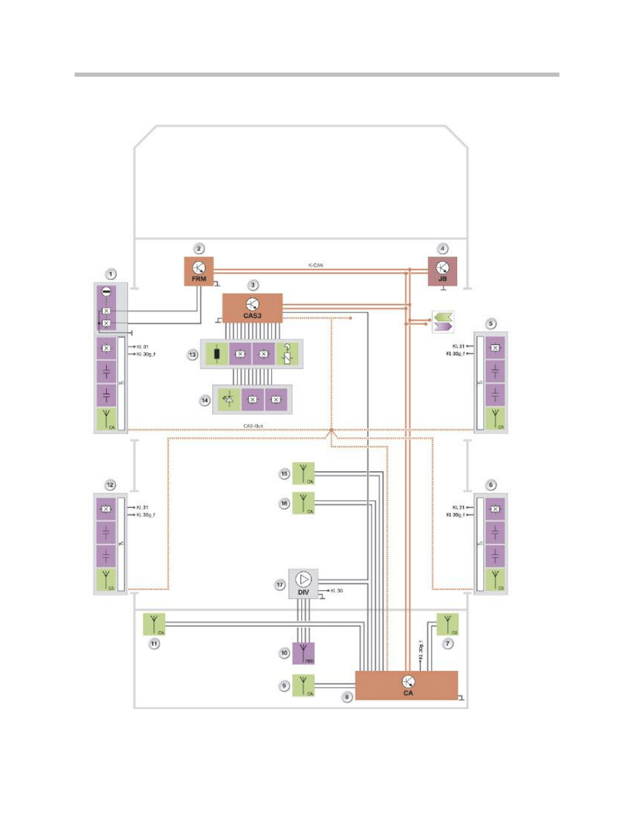
System Circuit Diagram

Legend for System Circuit Diagram
7
E70 Comfort Access
Index
Explanation
Index
Explanation
1
Driver's door lock cylinder, Outside door handle
electronics
10
Rear window with antenna for remote
control functionality
2
Footwell module FRM
11
Luggage compartment antenna
3
Car Access System 3 CAS 3
12
Rear driver's side outside
door handle electronics
4
Junction box control unit JB
13
ID transmitter slot
5
Front-passenger outside door handle electronics
14
START-STOP button
6
Passenger-side outside door handle electronics
inside
15
Front interior antenna
7
Luggage compartment antenna
16
Rear interior antenna
8
Comfort access CA
17
FBD antenna amplifier in diversity module
9
Luggage compartment antenna
outside tailgate area
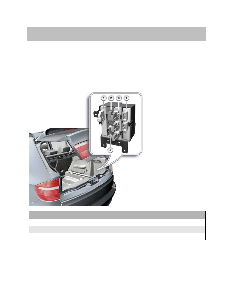
Control Unit
The Comfort Access control unit is located at the rear right of the luggage compartment.
Comfort Access controls the transmit antennas for the exterior and interior.
The signals from the outside door handle electronics modules are read in and trans-
ferred via the CAS bus to the Car Access System 3.
8
E70 Comfort Access
System Components
Index
Explanation
Index
Explanation
1
Comfort Access
4
Vertical Dynamic Management
2
Trailer module
5
Electronic ride-height control
3
Park Distance Control
9
E70 Comfort Access
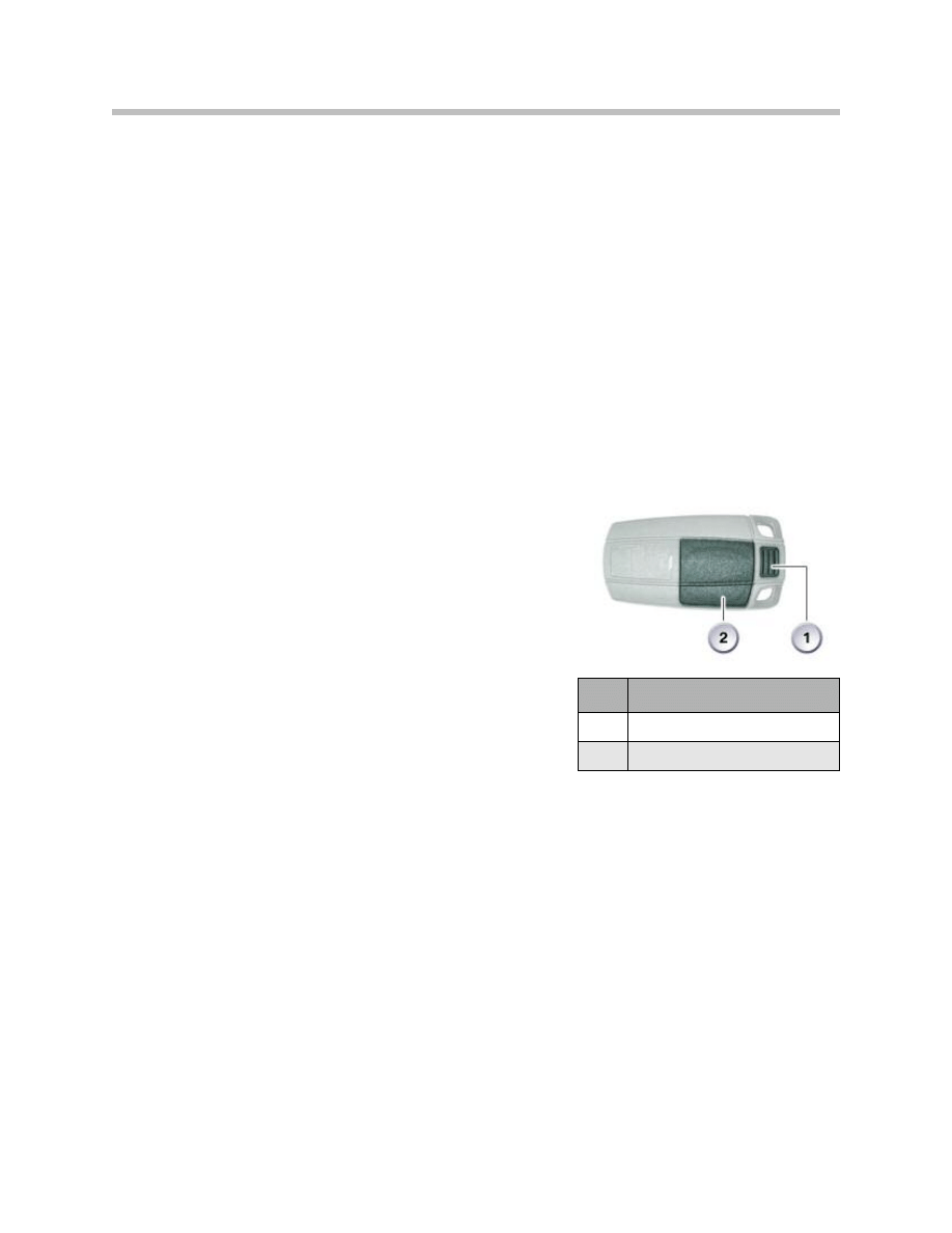
Control Elements
ID Transmitter
The ID transmitter for Comfort Access must be actuated by means of a radio signal. The
ID transmitter is therefore equipped with a receiver for the coded 125 kHz radio signal
that is transmitted by the outside door handle electronics module. The radio signal
enables the ID transmitter to register with the vehicle (authentication).
For this purpose, the ID transmitter emits a coded 868 MHz high-frequency signal to
enable identification of the ID transmitter as being valid and belonging to the vehicle.
The ID transmitter is exclusively responsible for use of Comfort Access.
The ID transmitter for Comfort Access has a battery, representing the externally identifi-
able difference compared to the remote control which features an integrated recharge-
able battery. The service life of the battery in the ID transmitter is about 2 years.
Voltage Monitoring
The ID transmitter monitors its own battery voltage.
The battery voltage is monitored in 2 stages.
The first stage signals to the Car Access System 3 that
the battery is flat. In response, the Car Access System 3
generates a check control message. The check control
message informs the customer that the battery needs to
be changed.
If the battery is not changed, the voltage monitoring
facility switches to the second stage. This means that
the data in the ID transmitter are saved. The ID transmit-
ter is then set "inoperable".
Data for Conditioned Based Service
When terminal status "terminal 15 ON" is selected, data for the Conditioned Based
Service is transferred to the ID transmitter using the interior antennas. The ID transmitter
then confirms that the transmission was received.
Index
Explanation
1
Unlock button for mechanical key
2
Battery compartment

Antennas for Comfort Access
Nine antennas are built in for Comfort Access.
Four of these can be found in the outside door handle electronics modules and five in
the vehicle interior/luggage compartment.
The antennas for the exterior and interior are inductive antennas and have a ferrite core
The antenna transmission frequency is 125 kHz. All messages that are sent via the
antennas are encrypted.
Antenna Installation Locations
Exterior Antennas
The exterior antennas are installed in the following locations on the E70:
• Front and rear driver's side outside door handle electronics
• Front and rear passenger-side outside door handle electronics
The antenna characteristic gives 2m of coverage around the vehicle.
Interior Antennas
The interior antennas are installed in the following locations on the E70:
• Passenger compartment, front
• Passenger compartment, center
• Luggage compartment, left and right
• Luggage compartment, near to the load edge, middle.
The antenna characteristic is spherical. The entire vehicle interior is covered by the
front and middle antennas.
Luggage Compartment Antenna
The luggage compartment antennas are of the same design as the interior antennas.
The antenna characteristic is configured so that the antennas in the luggage compart-
ment cover that whole area.
Interior Antenna
10
E70 Comfort Access

Outside Door Handle Electronics Module
The outside door handle is connected to terminal 30g and works inside a voltage range
of 9 V to 16 V.
The outside door handle electronics module is connected to the vehicle via the CAS bus
thus making available the information from the capacitive sensors and the Hall sensor.
With the aid of the 3 sensors, the electronic outside door handle module detects the
status of the outside door handle. Each change in the status of the outside door handle
module triggers the corresponding function.
These functions are:
• Trigger pulse by inserting a hand into the handle recess of the outside door handle;
Capacitive sensor 1
• Unlock request by pulling the outside door handle; Hall sensor
• Lock request by touching the sensitive area on the outside door handle; Capacitive
sensor 2
Sensors
To protect the battery, the outside door handle electronics module switches off the
capacitive sensors for the driver's side after 192 hours when the vehicle is at rest. The
passenger-side capacitive sensors are switched off after 72 hours.
Capacitive Sensor 1
A pulse is generated when a hand is inserted into the handle recess of the outside door
handle.The pulse wakes up the electronic circuitry in the outside door handle.
If the vehicle is in sleep mode, the electronics module will wake up the Comfort Access
and Car Access System 3. This involves the outside door handle electronics module
sending out a wake-up signal via the CAS-bus.
Comfort Access permanently switches on the remote control receiver in order to receive
the data sent from the ID transmitter.
Capacitive Sensor 2
Touching the sensitive area generates a signal from the capacitive sensor 2 until contact
ceases. The electronic module in the outside door handle sends the request via the CAS
bus. The request is to lock the vehicle.
Outside Door Handle Hall Sensor
The Hall sensor is a backup system for capacitive sensor 1. After 192 hours, the outside
door handle electronics in the driver's door enter sleep mode. This period begins when
the vehicle is locked or unlocked. The Hall sensor remains operational for a longer period.
Sleep mode reduces the power consumption of the outside door handle electronics by
switching off the capacitive sensors. By pulling twice on the outside door handle (two Hall
sensor status changes) the vehicle is unlocked.
11
E70 Comfort Access

Note: Both outside door handle electronics modules on the passenger-side
and the rear outside door handle electronics module on the driver's side
switch off after only 72 hours.
Door Locks
The capacitive sensor 1 initiates the vehicle unlocking procedure.
The door locks are equipped with an additional spring to ensure the vehicle can be
opened fast enough. The spring exerts pretension on the central locking drive unit for the
unlocking procedure. The door is already unlocked before an attempt is made to open it
with the outside door handle.
Note: If pulled very fast, however, it may be necessary to pull the outside door
handle a second time in order to open the door.
12
E70 Comfort Access

13
E70 Comfort Access
Comfort Access is divided into the following functions:
• Passive entry
• Passive go
• Passive exit
Comfort Access enables the central locking by allowing keyless
access to the vehicle.
The ID transmitter is an essential component of Comfort Access.
The ID transmitter comprises all remote control functionality, mean-
ing that it can be used in exactly the same way as a remote control.
Function Sequence
The ID transmitter sends out a coded signal as soon as the unlock or lock button is
pressed.
The signal from the ID transmitter is demodulated and conditioned in the remote control
receiver. This signal is also used by the Car Access System 3.
The ID transmitter can also be used to open the tailgate separately. For further informa-
tion, see the following chapter "Passive Entry for upper tailgate".
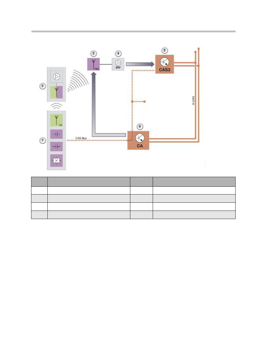
Passive Entry
The graphic in the next page shows the functional principle of "Passive entry".
Passive entry enables access to the vehicle without operating the ID transmitter (remote
control). The vehicle in sleep mode is woken with a valid ID transmitter (remote control).
Comfort Access is activated by grasping the outside door handle.
Principles of Operation
Note: The ID transmitter comprises the remote control function and is used
solely for Comfort Access.
For Comfort Access to work, the ID transmitter must be activated by
the vehicle via radio signal so it can register (be authenticated) with
the vehicle. This makes it possible to unlock the vehicle without
actively using the ID transmitter.
14
E70 Comfort Access
Index
Explanation
Index
Explanation
1
Outside door handle electronics module TAGE
5
Car Access System 3 CAS 3
2
ID transmitter
6
Comfort access CA
3
Rear window antenna
CAS bus
CAS bus
4
Remote control receiver in diversity module
K-CAN
Body CAN
Signal Path for Comfort Access

15
E70 Comfort Access
Unlocking Sequence
The capacitive sensor 1 in the outside door handle electronics module recognizes that
the handle has been grasped and activates the transmit antenna. The transmit antenna
sends a 125 kHz signal to the ID transmitter. The signal contains the authentication
request.
The ID transmitter sends a high-frequency signal of
868
MHz to the remote control
receiver to obtain authentication.
The Car Access System 3 checks the authentication of the ID transmitter.
Following successful authentication, the Car Access System 3 issues an approval to
unlock the vehicle and initiates the vehicle unlocking procedure. The junction box control
unit executes the unlocking procedure.
Passive Entry for Upper Tailgate
An authentication check also takes place before opening the upper tailgate. The junction
box control unit evaluates the status of the outside tailgate button. Pressing the outside
tailgate button changes its status.
The change in status is transmitted via the K-CAN.
The Comfort Access control unit prompts the ID transmitter to register and obtain
authentication from the vehicle. This prompt is sent by the antenna in the rear of the
vehicle.
After successful authentication, the tailgate can be unlocked and opened with the
outside tailgate button.
Passive Go
The Passive Go function makes it possible to start the vehicle without the ID transmitter
inserted in its holder.
Issuing Start Enable
Authorization to start the engine is only given when there is an ID transmitter in the vehi-
cle. Three seconds after the door has been opened the Car Access System 3 begins its
search for a valid ID transmitter. The Car Access System 3 requests the Comfort Access
control unit to prompt for identification of a valid ID transmitter.
The Comfort Access control unit sends the request via the interior antennas.
The ID transmitter responds using a high frequency range (868 MHz). If the ID transmitter
is authenticated, the Car Access System 3 grants permission for the engine to be started.
Note: The electronic immobilizer gives its own approval for the engine to be
started. This approval can only come when terminal 15 is selected.

16
E70 Comfort Access
Passive Exit
The Passive Exit function makes it possible to lock the vehicle without actively using the
ID transmitter.
Locking Procedure
After the vehicle door has been closed, the locking procedure is started by touching the
sensitive area on the outside door handle. The outside door handle electronics module
sends the request to unlock the vehicle via the CAS bus to the Comfort Access system.
Comfort Access checks via the outside antennas whether there is a valid ID transmitter in
the vicinity of the outside door handle (transmission range of the outside door handle
antennas).
The ID transmitter is instructed to send an authentication signal.
In turn, the identification sensor sends encrypted data via the high-frequency link to the
remote control receiver.
The Car Access System 3 checks whether the ID transmitter is valid.
On successful completion of the check, the Car Access System 3 issues the enable to
engage the central locking drive and initiates locking.
The junction box control unit activates the central locking drive units.

17
E70 Comfort Access
Special Functions
The Comfort Access additionally features the special functions described in the following
that are determined by the actions of the vehicle user.
Two ID transmitters Remain Inside the Vehicle
Using the interior antennas, the Car Access System 3 detects whether there is a valid ID
transmitter in the vehicle.
If the Car Access System 3 detects a valid ID transmitter in the vehicle interior and the
vehicle is locked by means of another valid ID transmitter (located outside), the ID trans-
mitter located in the vehicle interior is set to "invalid".
For Comfort Access purposes, this ID transmitter is considered as no longer belonging to
the vehicle until the vehicle is unlocked again.
Note: The "invalid" status only applies to the functions of Comfort Access. The
remote control functions are still available.
The ID Transmitter Inside the Luggage Compartment
On closing the tailgate, if an ID transmitter is located either in the luggage compartment
or the vehicle interior when the vehicle is locked, the tailgate is immediately reopened
automatically. An audible and visual signal draws the customer's attention to the fact that
the ID transmitter has been left in the luggage compartment or vehicle interior.
The Comfort Access control unit starts searching, prompted by the Car Access System
3, using the vehicle interior antennas and luggage compartment antennas.
If a valid ID transmitter is detected, the Car Access System 3 will not issue the enable for
locking the tailgate.
The tailgate cannot be closed before the ID transmitter has been removed and is located
outside the vehicle interior or luggage compartment.
Note: The tailgate can only be reopened when Comfort Access cannot find a
valid ID transmitter in the vicinity of the vehicle.
Starting Engine without ID Transmitter
This function allows the vehicle to be restarted within 10 seconds after the "Engine OFF"
switch has been activated, even if the ID transmitter is not detected. This function is
intended for cases where, for example, the ID transmitter is not detected due to high fre-
quency interference.

18
E70 Comfort Access
Check Control Message, Terminal 15
Comfort Access enables terminal selection without the ID transmitter being inserted in its
holder. It is possible that terminal 15 is selected by pressing the START-STOP button. A
corresponding check control message is shown in the instrument cluster after the door is
opened. An audible signal also sounds.
Note: The battery may be discharged if the driver ignores the warnings and
locks the vehicle.
Unintentional Wake-up Function
The vehicle cannot be woken simply by someone gripping the outside door handle. A
valid ID transmitter must be detected in the vicinity of the vehicle.
Locking with Engine Running
The vehicle can also be unlocked with the engine running if the engine was started with
Passive Go. When leaving the vehicle, the ID transmitter should also be taken and the
vehicle locked from the outside.
Document Outline
- Main Menu
- E70 Introduction
- E70 Glovebox
- E70 Powertrain
- E70 Gasoline Engines
- E70 Transmissions
- E70 Voltage Supply and Bus Systems
- E70 Car Access System 3
- E70 Energy Management
- E70 Chassis Dynamics
- E70 Lateral Dynamics Systems
- E70 Vertical Dynamics Systems
- E70 Longitudinal Dynamics Systems
- E70 Central Locking
- E70 Power Windows
- E70 Comfort Access
- E70 Wipe/Wash System
- E70 Panorama Glass Sunroof
- E70 Seats
- E70 Automatic Tailgate
- E70 Steering Column Switch Cluster
- E70 Exterior Lighting
- E70 Interior Lighting
- E70 Adaptive Headlight System
- E70 Park Distance Control
- E70 Rear-view Camera
- E70 Anti-Theft Alarm System
- E70 Outside Mirrors
- E70 Displays Indicators and Controls
- E70 Head-up Display
- E70 Information and Communication
- E70 Audio Systems
- E70 Rear Seat Entertainment
- E70 Climate Control Systems
- E70 Passive Safety Systems
Wyszukiwarka
Podobne podstrony:
06 E65 66 Comfort Access
03b E70 Car Access System 3
05 1 F01 Comfort Access
04 QueryByExample Access
04a Różnice CerapurSmart Comfort
Access 2002 Projektowanie baz danych Ksiega eksperta ac22ke
access 4 progress check unit 6,7,8, Access 4 Progress Check 6
Access 3 Test 7 A
Configuration Guide WAN Access(V100R006C00 02)
access programowanie w vba
Access to History 001 Gas Attack! The Canadians at Ypres, 1915
Ćwiczenie nr 1 (Access 2007)
Open Access and Academic Journal Quality
access 3
CISCO Accessible Theme8
Access 2003 dla każdego
Lab10 integracja z ms access
A Łozowska, Technologie informacyjne Między DOI a Open Access
więcej podobnych podstron