1204D–01
A65749
E1
OX1A
OX1B
A65936
–
EMISSION CONTROL
EMISSION CONTROL SYSTEM
12–1
1001
Author:
Date:
2004 COROLLA (RM1037U)
EMISSION CONTROL SYSTEM
ON–VEHICLE INSPECTION
1.
INSPECT AIR–FUEL RATIO COMPENSATION SYS-
TEM
HINT:
You can also check the system by choosing ”DATA MONITOR”,
then ”O
2
SENSOR OUTPUT VOLTAGE” on the monitor of the
hand–held tester.
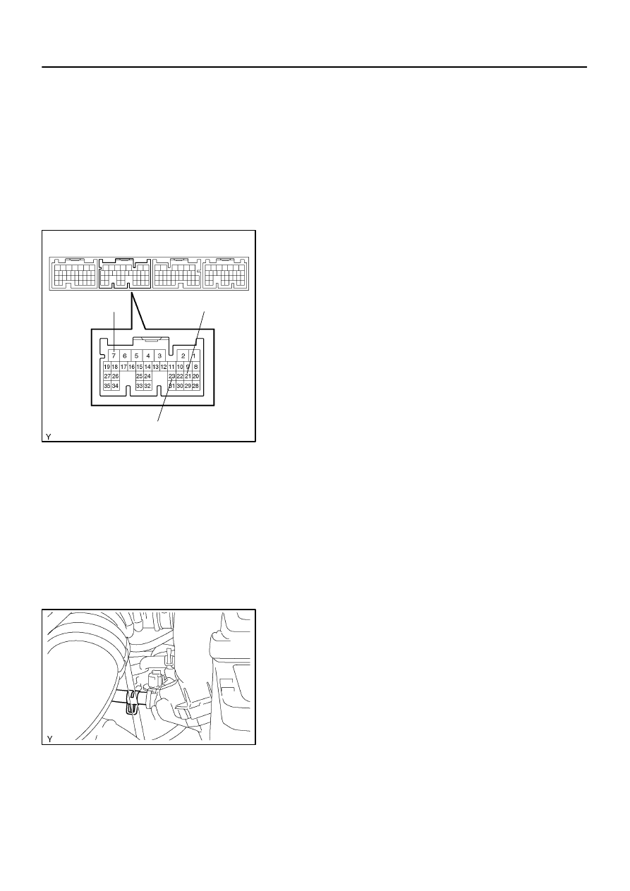
(a)
Connect the hand–held tester to the terminal 23 (OX1A)
⇔
7 (E1) and 21 (OX1B)
⇔
7 (E1) of the ECM.
CAUTION:
Connect test leads from the back side of the connector with
the ECU connected.
(b)
Warm up the oxygen sensor with the engine speed at
2,500 rpm for approx. 2 minutes.
(c)
Confirm that the voltage changes between 0V to 1V with
the engine speed at 2,500 rpm.
OK:
The voltage changes more than 8 times in 10 se-
conds.
CAUTION:
Perform the check immediately after the end of the
warming up.
If not confirming the change of voltage, warming up
the oxygen sensor again.
2.
INSPECT FUEL CUT OFF RPM
(a)
Increase the engine speed to at least 3,500 rpm.
(b)
Use a sound scope to check for injector operating noise.
(c)
Check that when the throttle lever is released, injector operation noise stops momentarily and then
resumes.
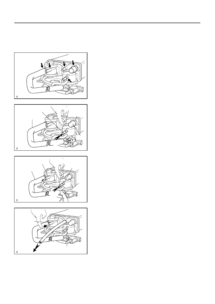
3.
INSPECT EVAPORATIVE EMISSION CONTROL SYS-
TEM
(a)
After starting the engine, disconnect the vacuum hose
shown in the illustration.
(b)
Confirm vacuum occurs at the vsv port, when choosing
”ACTIVE TEST” and ”PURGE VSV” according to the dis-
play on hand–held tester.
(c)
Finish ”ACTIVE TEST”, then connect the vacuum hose
again.
(d)
After going to ”ECM DATA MONITOR” on the hand–held
tester, choose ”PURGE VSV” to check the operation of
the purge VSV.
(e)
After warm up the engine and drive the vehicle, confirm
the VSV turns on from off.
Vacuum Gauge
B06544
A65906
Battery
Vacuum Gauge
B06545
12–2
–
EMISSION CONTROL
EMISSION CONTROL SYSTEM
1002
Author:
Date:
2004 COROLLA (RM1037U)
4.
INSPECT EVAP SYSTEM LINE
(a)
Warm up the engine and stop the engine. Allow the en-
gine to warm up to normal operating temperature.
(b)
Install a vacuum gauge (EVAP control system test equip-
ment vacuum gauge) to the EVAP service port on the
purge line.
(c)
TOYOTA Hand–Held Tester:
Forced driving of the VSV for the EVAP.
(1)
Connect a TOYOTA hand–held tester to the DLC3
(2)
Start the engine.
(3)
Push the TOYOTA hand–held tester main switch
ON.
(4)
Use the ACTIVE TEST mode on the TOYOTA
hand–held tester to operate the VSV for the EVAP.
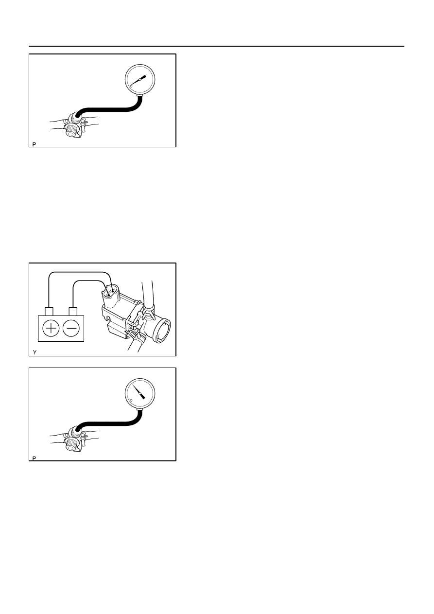
(d)
If you have no TOYOTA Hand–Held Tester:
Forced driving of the VSV for the EVAP.
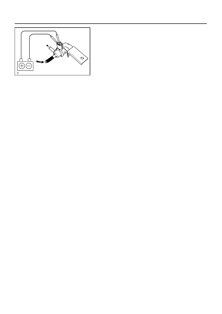
(1)
Disconnect the VSV connector for the EVAP.
(2)
Connect the positive (+) and negative (–) leads from
the battery to the VSV terminals for the EVAP.
(3)
Start the engine.
(e)
Check the vacuum at idle
Vacuum:
Maintain at 0.368 – 19.713 in.Hg (5 –268 in.Aq) for over
5 seconds.
HINT:
If the vacuum does not change, you can conclude that the hose
connecting the VSV to the service port has come loose or is
blocked, or the VSV is malfunctioning.
(f)
TOYOTA Hand–Held Tester:
Conclude forced driving of the VSV for the EVAP.
(1)
Stop the engine.
(2)
Disconnect the TOYOTA hand–held tester from the
DLC3.
(g)
If you have no TOYOTA Hand–Held tester:
Conclude forced driving of the VSV for the EVAP.
(1)
Stop the engine.
A63957
Air Drain Hose
Hose Clipper
Pressure Gauge
Pressure
B06546
A52634
–
EMISSION CONTROL
EMISSION CONTROL SYSTEM
12–3
1003
Author:
Date:
2004 COROLLA (RM1037U)
(2)
Disconnect the positive (+) and negative (–) leads
from the battery from the VSV terminals for the
EVAP.
(3)
Connect the VSV connector for the EVAP.
(h)
Disconnect the vacuum gauge from the EVAP service
port on the purge line.
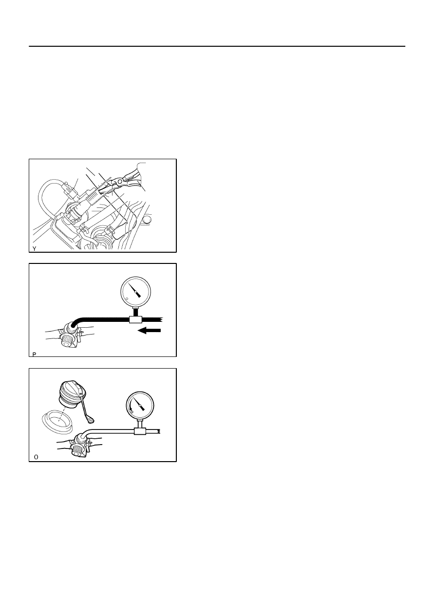
(i)
Connect a pressure gauge to the EVAP service port on
the purge line.
(j)
Check the pressure.
(1)
Close off the air drain hose at the marked position
of the canister with a hose clipper or similar instru-
ment.
(2)
Add the pressure (13.5 – 15.5 in. Aq) from the EVAP
service port.
Pressure:
2 minutes after the pressure is added, the gauge
should be over 7.7–8.8 in.Aq.
HINT:
If you can not add pressure, you can conclude that the hose
connecting the VSV – canister – fuel tank has slipped off or the
VSV is open.
(3)
Check if the pressure decreases when the fuel tank
cap is removed while adding pressure.
HINT:
If the pressure dose not decrease when the filler cap is re-
moved, then you can conclude that the hose connecting the
service port to the fuel tank is blocked, etc.
(k)
Disconnect the pressure gauge from the EVAP service
port on the purge line.
A65905
EVAP Line Hose
A
A63960
EVAP Line Hose
Purge Line Hose
Air
A63962
Air Inlet
Line Hose
Air
12–4
–
EMISSION CONTROL
EMISSION CONTROL SYSTEM
1004
Author:
Date:
2004 COROLLA (RM1037U)
5.
CHECK AIRTIGHTNESS IN FUEL TANK AND FILLER
PIPE
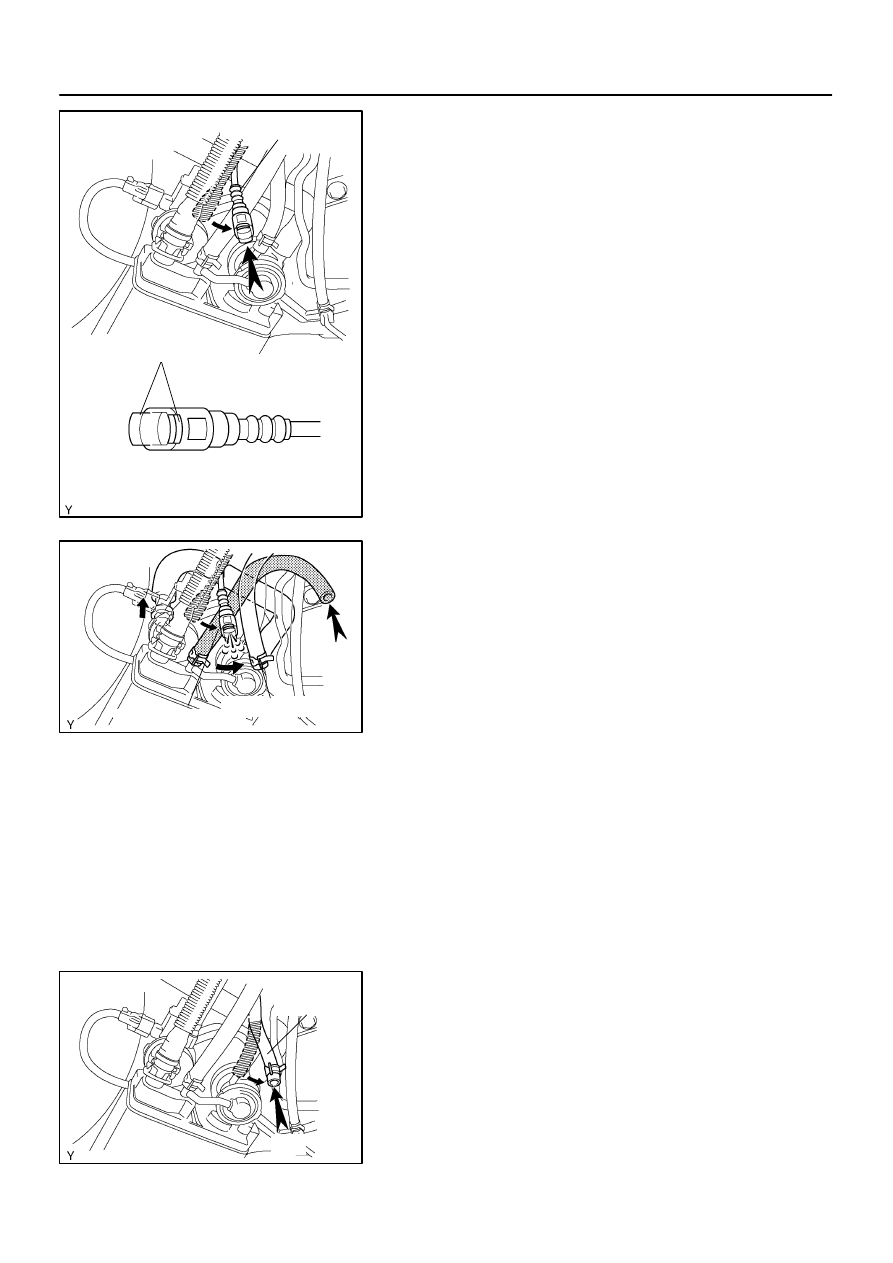
(a)
Disconnect the EVAP line hose from the charcoal canis-
ter.
(1)
Pinch portion A.
(2)
Pull out the connector.
(b)
Pressurize and make the internal pressure in the fuel tank
4 kPa (41 gf/cm
2
, 0.58 psi).
(c)
Check that the internal pressure of the fuel tank can be
hold for 1 minute.
(d)
Check the connected portions of each hose and pipe.
(e)
Check the installed parts on the fuel tank.
If there is no abnormality, replace the fuel tank and filler pipe.
(f)
Reconnect the EVAP line hose to the charcoal canister.
6.
INSPECT FUEL CUT OFF VALVE AND FILL CHECK
VALVE
(a)
Disconnect the purge line hose and EVAP line hose from
the charcoal canister.
(b)
Plug the cap to the air drain hose.
(c)
Pressurize 4 kPa (41 gf/cm
2
, 0.58 psi) to the purge port
and check that there is ventilation through the EVAP line
hose.
HINT:
In the condition that the fuel is full, as the float value of the fill
check valve is closed and has no ventilation, it is necessary to
check the fuel amount (volume).
(d)
Check if there is anything struck in the vent line hose and
EVAP line hose.
If there is no stuck in hoses, replace the fuel cut off valve and
fill check valve.
(e)
Reconnect the purge line hose and EVAP line hose to the
charcoal canister.
7.
CHECK AIR INLET LINE
(a)
Disconnect the air inlet line hose from the charcoal canis-
ter.
(b)
Check that there is ventilation in the air inlet line.
(c)
Reconnect the air inlet line hose to the charcoal canister.

A65907
A60559
+B
HT
Gasket
B11870
–
EMISSION CONTROL
EMISSION CONTROL SYSTEM
12–5
1005
Author:
Date:
2004 COROLLA (RM1037U)
8.
VISUALLY INSPECT HOSES, CONNECTIONS AND
GASKETS
(a)
Check for cracks, leaks or damage.
HINT:
Separation of the engine oil dipstick, oil filler cap, PCV hose,
etc. may cause the engine to run out of turn. Disconnection,
looseness or cracks in the parts of the air induction system be-
tween the throttle body and cylinder head will allow air suction
and cause the engine to run out of turn.
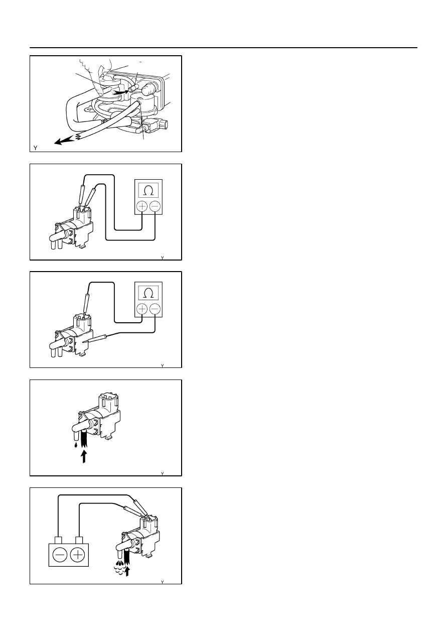
9.
INSPECT HEATER RESISTANCE OF HEATED OXY-
GEN SENSOR
(a)
Disconnect the oxygen sensor connector.
(b)
Using an ohmmeter, measure the resistance between the
terminals HT and +B.
Resistance: 11 – 16
Ω
at 20
C (68
F)
10.
INSPECT FUEL TANK CAP
(a)
Visually check if the cap and/or gasket are deformed or
damaged.
1204E–01
A63966
A63968
Air
Purge Port
Vent Port
Air Drain Port
Cap
EVAP Port
A63970
Air Drain Port
Purge Port
Air Inlet Port
EVAP Port
Air
A63972
Air Inlet
Port
Vacuum
Purge Port
12–6
–
EMISSION CONTROL
EMISSION CONTROL SYSTEM
1006
Author:
Date:
2004 COROLLA (RM1037U)
INSPECTION
1.
CHARCOAL CANISTER ASSY
(a)
Visually check the charcoal canister for cracks or dam-
age.
(b)
Inspect the charcoal canister operation.
(1)
Plug the vent port with the cap.
(2)
While holding the purge port closed, blow air (1.76
kPa, 18 gf/cm
2
, 0.26 psi) into the EVAP port and
check that air flows from the air drain port.
(3)
While holding the purge port and the air drain port
closed, blow air (1.76 kPa, 18 gf/cm
2
, 0.26 psi) into
the EVAP port and check that air does not flow from
the air inlet port.
(4)
Apply vaccum (3.43 kPa, 25.7 mmHg, 1.01 in.Hg)
to the purge port, check that the vacuum dose not
decrease when the air inlet port is closed, and
check that the vacuum decreases when the air inlet
port is released.
A65903
Air Inlet
Port
Purge Port
Vacuum
EVAP Port
A65908
Ohmmeter
Continuity
A65909
Ohmmeter
No Continuity
A65910
E
F
Air
A65911
E
F
Air
Battery
–
EMISSION CONTROL
EMISSION CONTROL SYSTEM
12–7
1007
Author:
Date:
2004 COROLLA (RM1037U)
(5)
While holding the air inlet port closed, apply vacuum
(3.43 kPa, 25.7 mmHg, 1.01 in.Hg) to the EVAP port
and check that air flows into the purge port.
If operation is not as spacified, replace the charcoal canister.
(6)
Remove the hose and cap from vent port.
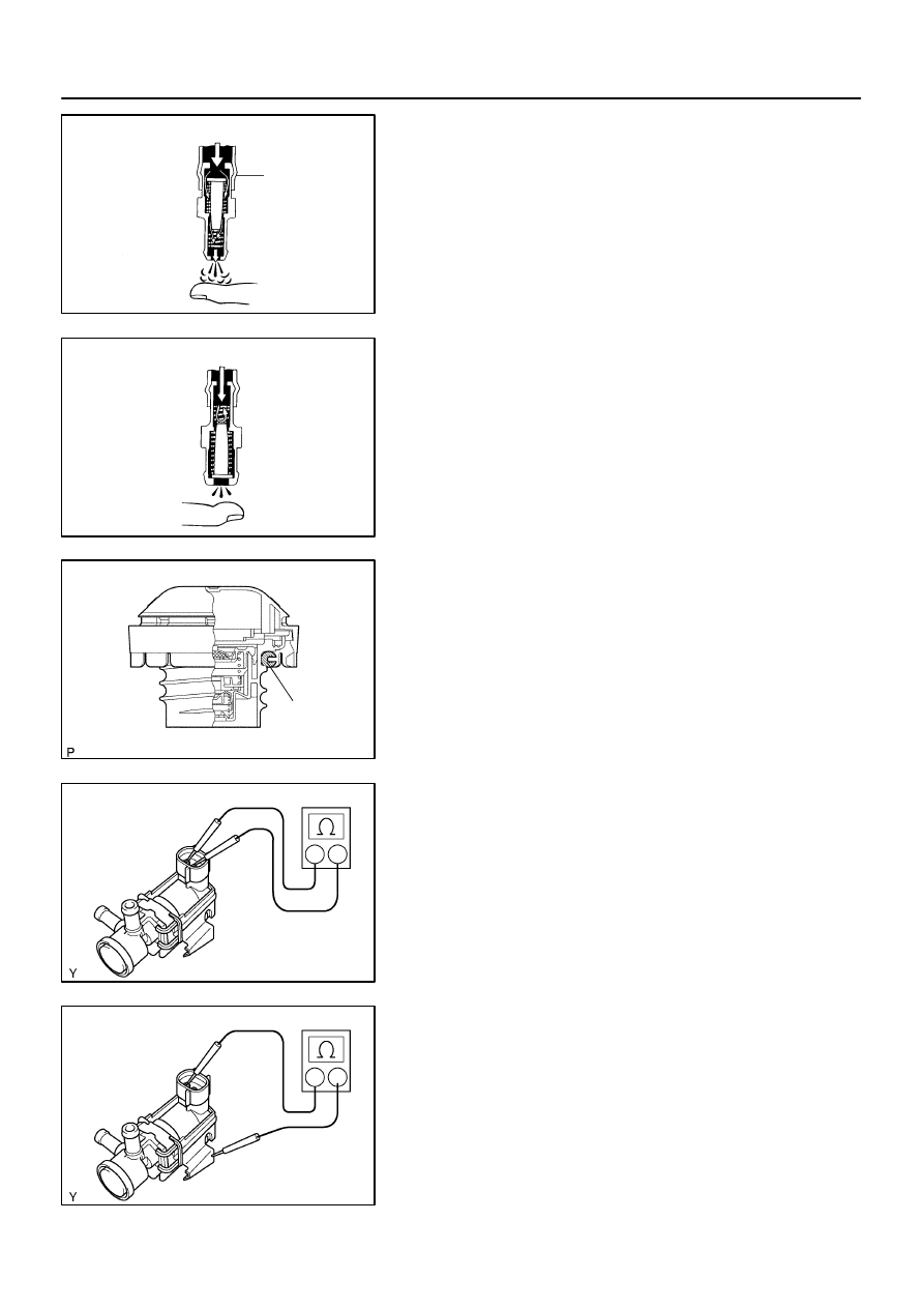
(c)
Inspect VSV for Pressure Swiching Valve
(1)
Using an ohmmeter, check that there is continuity
between the terminals.
Resistance: 37 – 44
Ω
at 20
C (68
F)
If there is no continuity, replace the VSV.
(2)
Using an ohmmeter, check that there is no continu-
ity between each terminal and the body.
If there is continuity, replace the VSV.
(3)
Check that air does not flow from ports E to F.
(4)
Apply battery positive voltage across the terminals.
(5)
Check that air flows from ports E to F.
If operation is not as specified, replace the VSV.
Cylinder Head Side
Clean Hose
P11834
Intake Manifold Side
P11831
Gasket
B11870
A65912
Ohmmeter
Continuity
A65913
No Continuity
Ohmmeter
12–8
–
EMISSION CONTROL
EMISSION CONTROL SYSTEM
1008
Author:
Date:
2004 COROLLA (RM1037U)
2.
VENTILATION VALVE SUB–ASSY
(a)
Install clean hose to the PCV valve.
(b)
Inspect the PCV valve operation.
(1)
Blow air into the cylinder head side, and check that
air passes through easily.
CAUTION:
Do not suck air through the valve. Petroleum substances
inside the valve air harmful.
(2)
Blow air into the intake manifold side, and check
that air passes through with difficulty.
If operation is not as specified, replace the PCV valve.
(c)
Remove clean hose from the PCV valve.
3.
FUEL TANK CAP ASSY
(a)
Visually check if cap and/or gasket are deformed or dam-
aged.
If necessary, repair or replace the cap.
4.
VACUUM SWITCHING VALVE NO.1
(a)
Inspect VSV for evaporative emission (EVAP).
(1)
Using an ohmmeter, check that there is continuity
between the terminals.
Resistance: 27 – 33
Ω
at 20
C (68
F)
If there is no continuity, replace the VSV.
(2)
Using an ohmmeter, check that there is no continu-
ity between each terminal and the body.
If there is continuity, replace the VSV.
A65914
F
Air
E
A65915
Battery
F
Air
E
A65916
Ohmmeter
Continuity
A65917
Ohmmeter
No Continuity
A65918
Air
A
B
–
EMISSION CONTROL
EMISSION CONTROL SYSTEM
12–9
1009
Author:
Date:
2004 COROLLA (RM1037U)
(3)
Check that air flows from ports E to F.
(4)
Apply battery positive voltage across the terminals.
(5)
Check that air does not flow from ports E to F.
If operation is not as specified, replace the VSV.
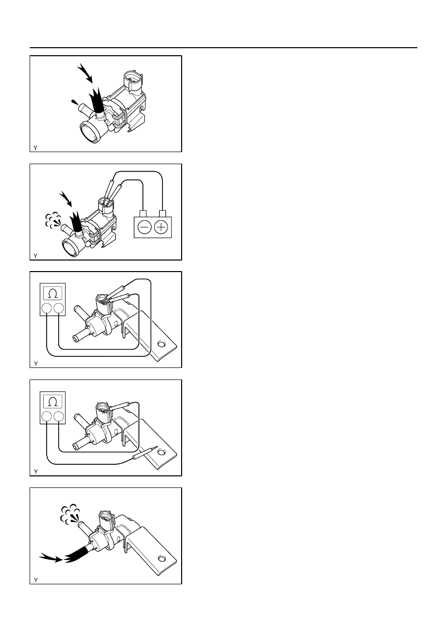
5.
VACUUM SWITCHING VALVE ASSY NO.1
(a)
Inspect VSV for Canister Closed valve (CCV).
(1)
Using an ohmmeter, check that there is continuity
between the terminals.
Resistance: 25 – 30
Ω
at 20
C (68
F)
If there is no continuity, replace the VSV.
(2)
Using an ohmmeter, check that there is no continu-
ity between each terminal and the body.
If there is continuity, replace the VSV.
(3)
Check that air flows from ports A to B.
A65919
Battery
Air
A
B
12–10
–
EMISSION CONTROL
EMISSION CONTROL SYSTEM
1010
Author:
Date:
2004 COROLLA (RM1037U)
(4)
Apply battery positive voltage across the terminals.
(5)
Check that air does not flow from ports A to B.
If operation is not as specified, replace the VSV.
Wyszukiwarka
Podobne podstrony:
12 Emission Control
12 Emission Control
10 Emission control system
12 Werntges controling KNX from Linux and USB
07 emission control system
6J Emissions Controls
9 10 Emission Control Info SV650Y
EMISSION CONTROL
10 Emission control system
więcej podobnych podstron