1-1
Numerical Representations
1-2
Digital and Analog Systems
1-3
Digital Number Systems
1-4
Representing Binary
Quantities
1-5
Digital Circuits/Logic
Circuits
■
OUTLINE
I N T R O D U C T O R Y
C O N C E P T S
C H A P T E R 1
1-6
Parallel and Serial
Transmission
1-7
Memory
1-8
Digital Computers
TOCCMC01_0131725793.QXD 11/26/05 12:49 AM Page 2

3
■
OBJECTIVES
Upon completion of this chapter, you will be able to:
■
Distinguish between analog and digital representations.
■
Cite the advantages and drawbacks of digital techniques compared
with analog.
■
Understand the need for analog-to-digital converters (ADCs) and
digital-to-analog converters (DACs).
■
Recognize the basic characteristics of the binary number system.
■
Convert a binary number to its decimal equivalent.
■
Count in the binary number system.
■
Identify typical digital signals.
■
Identify a timing diagram.
■
State the differences between parallel and serial transmission.
■
Describe the property of memory.
■
Describe the major parts of a digital computer and understand their
functions.
■
Distinguish among microcomputers, microprocessors, and
microcontrollers.
■
INTRODUCTION
In today’s world, the term
digital has become part of our everyday vocabu-
lary because of the dramatic way that digital circuits and digital techniques
have become so widely used in almost all areas of life: computers, automa-
tion, robots, medical science and technology, transportation, telecommuni-
cations, entertainment, space exploration, and on and on. You are about to
begin an exciting educational journey in which you will discover the funda-
mental principles, concepts, and operations that are common to all digital
systems, from the simplest on/off switch to the most complex computer. If
this book is successful, you should gain a deep understanding of how all
digital systems work, and you should be able to apply this understanding to
the analysis and troubleshooting of any digital system.
We start by introducing some underlying concepts that are a vital part
of digital technology; these concepts will be expanded on as they are
needed later in the book. We also introduce some of the terminology that is
necessary when embarking on a new field of study, and add to this list of
important terms in every chapter.
TOCCMC01_0131725793.QXD 11/26/05 12:49 AM Page 3

1-1
NUMERICAL REPRESENTATIONS
In science, technology, business, and, in fact, most other fields of endeavor,
we are constantly dealing with
quantities. Quantities are measured, moni-
tored, recorded, manipulated arithmetically, observed, or in some other way
utilized in most physical systems. It is important when dealing with various
quantities that we be able to represent their values efficiently and accu-
rately. There are basically two ways of representing the numerical value of
quantities: analog and digital.
Analog Representations
In analog representation a quantity is represented by a continuously vari-
able, proportional indicator. An example is an automobile speedometer from
the classic muscle cars of the 1960s and 1970s. The deflection of the needle
is proportional to the speed of the car and follows any changes that occur as
the vehicle speeds up or slows down. On older cars, a flexible mechanical
shaft connected the transmission to the speedometer on the dash board. It is
interesting to note that on newer cars, the analog representation is usually
preferred even though speed is now measured digitally.
Thermometers before the digital revolution used analog representation to
measure temperature, and many are still in use today. Mercury thermometers
use a column of mercury whose height is proportional to temperature. These
devices are being phased out of the market because of environmental con-
cerns, but nonetheless they are an excellent example of analog representa-
tion. Another example is an outdoor thermometer on which the position of the
pointer rotates around a dial as a metal coil expands and contracts with tem-
perature changes. The position of the pointer is proportional to the tempera-
ture. Regardless of how small the change in temperature, there will be a
proportional change in the indication.
In these two examples the physical quantities (speed and temperature) are
being coupled to an indicator by purely mechanical means. In electrical analog
systems, the physical quantity that is being measured or processed is converted
to a proportional voltage or current (electrical signal). This voltage or current
is then used by the system for display, processing, or control purposes.
Sound is an example of a physical quantity that can be represented by an
electrical analog signal. A microphone is a device that generates an output
voltage that is proportional to the amplitude of the sound waves that strike
it. Variations in the sound waves will produce variations in the microphone’s
output voltage. Tape recordings can then store sound waves by using the out-
put voltage of the microphone to proportionally change the magnetic field on
the tape.
Analog quantities such as those cited above have an important charac-
teristic, no matter how they are represented:
they can vary over a continuous
range of values. The automobile speed can have any value between zero and,
say, 100 mph. Similarly, the microphone output might have any value within
a range of zero to 10 mV (e.g., 1 mV, 2.3724 mV, 9.9999 mV).
Digital Representations
In digital representation the quantities are represented not by continuously
variable indicators but by symbols called
digits. As an example, consider the
digital clock, which provides the time of day in the form of decimal digits that
represent hours and minutes (and sometimes seconds). As we know, the time
of day changes continuously, but the digital clock reading does not change
continuously; rather, it changes in steps of one per minute (or per second). In
4
C
HAPTER
1/
I
NTRODUCTORY
C
ONCEPTS
TOCCMC01_0131725793.QXD 11/26/05 12:49 AM Page 4
other words, this digital representation of the time of day changes in
discrete
steps, as compared with the representation of time provided by an analog ac
line-powered wall clock, where the dial reading changes continuously.
The major difference between analog and digital quantities, then, can be
simply stated as follows:
analog
continuous
digital
discrete (step by step)
Because of the discrete nature of digital representations, there is no ambiguity
when reading the value of a digital quantity, whereas the value of an analog
quantity is often open to interpretation. In practice, when we take a measure-
ment of an analog quantity, we always “round” to a convenient level of preci-
sion. In other words, we digitize the quantity. The digital representation is the
result of assigning a number of limited precision to a continuously variable
quantity. For example, when you take your temperature with a mercury (ana-
log) thermometer, the mercury column is usually between two graduation lines,
but you would pick the nearest line and assign it a number of, say, 98.6°F.
K
K
S
ECTION
1-2/
D
IGITAL AND
A
NALOG
S
YSTEMS
5
REVIEW QUESTION *
1. Concisely describe the major difference between analog and digital
quantities.
*Answers to review questions are found at the end of the chapter in which they occur.
1-2
DIGITAL AND ANALOG SYSTEMS
A digital system is a combination of devices designed to manipulate logical
information or physical quantities that are represented in digital form; that
is, the quantities can take on only discrete values. These devices are most
EXAMPLE 1-1
Which of the following involve analog quantities and which involve digital
quantities?
(a) Ten-position switch
(b) Current flowing from an electrical outlet
(c) Temperature of a room
(d) Sand grains on the beach
(e) Automobile fuel gauge
Solution
(a) Digital
(b) Analog
(c) Analog
(d) Digital, since the number of grains can be only certain discrete (integer)
values and not every possible value over a continuous range
(e) Analog, if needle type; digital, if numerical readout or bar graph display
TOCCMC01_0131725793.QXD 11/26/05 12:49 AM Page 5

often electronic, but they can also be mechanical, magnetic, or pneumatic.
Some of the more familiar digital systems include digital computers and cal-
culators, digital audio and video equipment, and the telephone system—the
world’s largest digital system.
An analog system contains devices that manipulate physical quantities
that are represented in analog form. In an analog system, the quantities can
vary over a continuous range of values. For example, the amplitude of the
output signal to the speaker in a radio receiver can have any value between
zero and its maximum limit. Other common analog systems are audio ampli-
fiers, magnetic tape recording and playback equipment, and a simple light
dimmer switch.
Advantages of Digital Techniques
An increasing majority of applications in electronics, as well as in most other
technologies, use digital techniques to perform operations that were once
performed using analog methods. The chief reasons for the shift to digital
technology are:
1.
Digital systems are generally easier to design. The circuits used in digital
systems are
switching circuits, where exact values of voltage or current
are not important, only the range (HIGH or LOW) in which they fall.
2.
Information storage is easy. This is accomplished by special devices and
circuits that can latch onto digital information and hold it for as long as
necessary, and mass storage techniques that can store billions of bits of
information in a relatively small physical space. Analog storage capabil-
ities are, by contrast, extremely limited.
3.
Accuracy and precision are easier to maintain throughout the system. Once
a signal is digitized, the information it contains does not deteriorate as it
is processed. In analog systems, the voltage and current signals tend to
be distorted by the effects of temperature, humidity, and component tol-
erance variations in the circuits that process the signal.
4.
Operation can be programmed. It is fairly easy to design digital systems
whose operation is controlled by a set of stored instructions called a
program. Analog systems can also be programmed, but the variety and
the complexity of the available operations are severely limited.
5.
Digital circuits are less affected by noise. Spurious fluctuations in voltage
(noise) are not as critical in digital systems because the exact value of a
voltage is not important, as long as the noise is not large enough to pre-
vent us from distinguishing a HIGH from a LOW.
6.
More digital circuitry can be fabricated on IC chips. It is true that analog
circuitry has also benefited from the tremendous development of IC
technology, but its relative complexity and its use of devices that cannot
be economically integrated (high-value capacitors, precision resistors,
inductors, transformers) have prevented analog systems from achieving
the same high degree of integration.
Limitations of Digital Techniques
There are really very few drawbacks when using digital techniques. The two
biggest problems are:
The real world is analog.
Processing digitized signals takes time.
6
C
HAPTER
1/
I
NTRODUCTORY
C
ONCEPTS
TOCCMC01_0131725793.QXD 11/26/05 12:49 AM Page 6
Most physical quantities are analog in nature, and these quantities are often
the inputs and outputs that are being monitored, operated on, and controlled
by a system. Some examples are temperature, pressure, position, velocity, liq-
uid level, flow rate, and so on. We are in the habit of expressing these quan-
tities
digitally, such as when we say that the temperature is
(
when
we want to be more precise), but we are really making a digital approxima-
tion to an inherently analog quantity.
To take advantage of digital techniques when dealing with analog inputs
and outputs, four steps must be followed:
1. Convert the physical variable to an electrical signal (analog).
2. Convert the electrical (analog) signal into digital form.
3. Process (operate on) the digital information.
4. Convert the digital outputs back to real-world analog form.
An entire book could be written about step 1 alone. There are many kinds
of devices that convert various physical variables into electrical analog sig-
nals (sensors). These are used to measure things that are found in our “real”
analog world. On your car alone, there are sensors for fluid level (gas tank),
temperature (climate control and engine), velocity (speedometer), accelera-
tion (airbag collision detection), pressure (oil, manifold), and flow rate (fuel),
to name just a few.
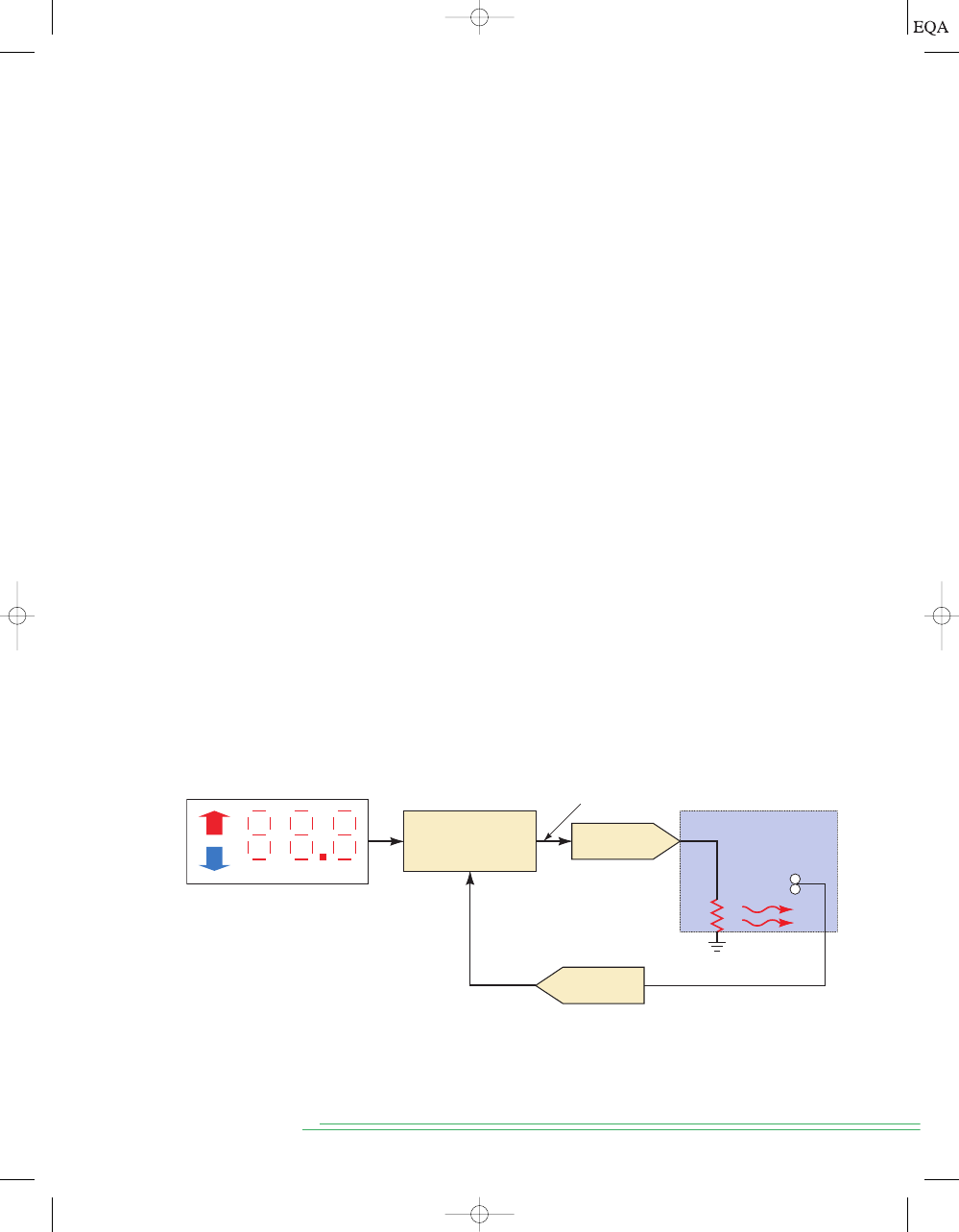
To illustrate a typical system that uses this approach Figure 1-1 describes
a precision temperature regulation system. A user pushes up or down buttons
to set the desired temperature in
increments (digital representation). A
temperature sensor in the heated space converts the measured temperature
to a proportional voltage. This analog voltage is converted to a digital quan-
tity by an analog-to-digital converter (ADC). This value is then compared to
the desired value and used to determine a digital value of how much heat is
needed. The digital value is converted to an analog quantity (voltage) by a
digital-to-analog converter (DAC). This voltage is applied to a heating ele-
ment, which will produce heat that is related to the voltage applied and will
affect the temperature of the space.
0.1°
63.8°
64°
S
ECTION
1-2/
D
IGITAL AND
A
NALOG
S
YSTEMS
7
FIGURE 1-1
Block diagram of a precision digital temperature control system.
Temperature controlled
space
Digital input:
Set Desired Temperature
Digital Processor
Digital–Analog
conversion
Analog–Digital
conversion
Heat
Sensor
Analog signal representing
actual temperature
Digital signal representing
actual temperature
Digital signal representing
power (voltage) to heater
+
–
Another good example where conversion between analog and digital
takes place is in the recording of audio. Compact disks (CDs) have replaced
cassette tapes because they provide a much better means for recording and
TOCCMC01_0131725793.QXD 12/19/05 1:44 PM Page 7
playing back music. The process works something like this: (1) sounds from
instruments and human voices produce an analog voltage signal in a micro-
phone; (2) this analog signal is converted to a digital format using an analog-
to-digital conversion process; (3) the digital information is stored on the CD’s
surface; (4) during playback, the CD player takes the digital information
from the CD surface and converts it into an analog signal that is then ampli-
fied and fed to a speaker, where it can be picked up by the human ear.
The second drawback to digital systems is that processing these digitized
signals (lists of numbers) takes time. And we also need to convert between
the analog and digital forms of information, which can add complexity and
expense to a system. The more precise the numbers need to be, the longer it
takes to process them. In many applications, these factors are outweighed by
the numerous advantages of using digital techniques, and so the conversion
between analog and digital quantities has become quite commonplace in the
current technology.
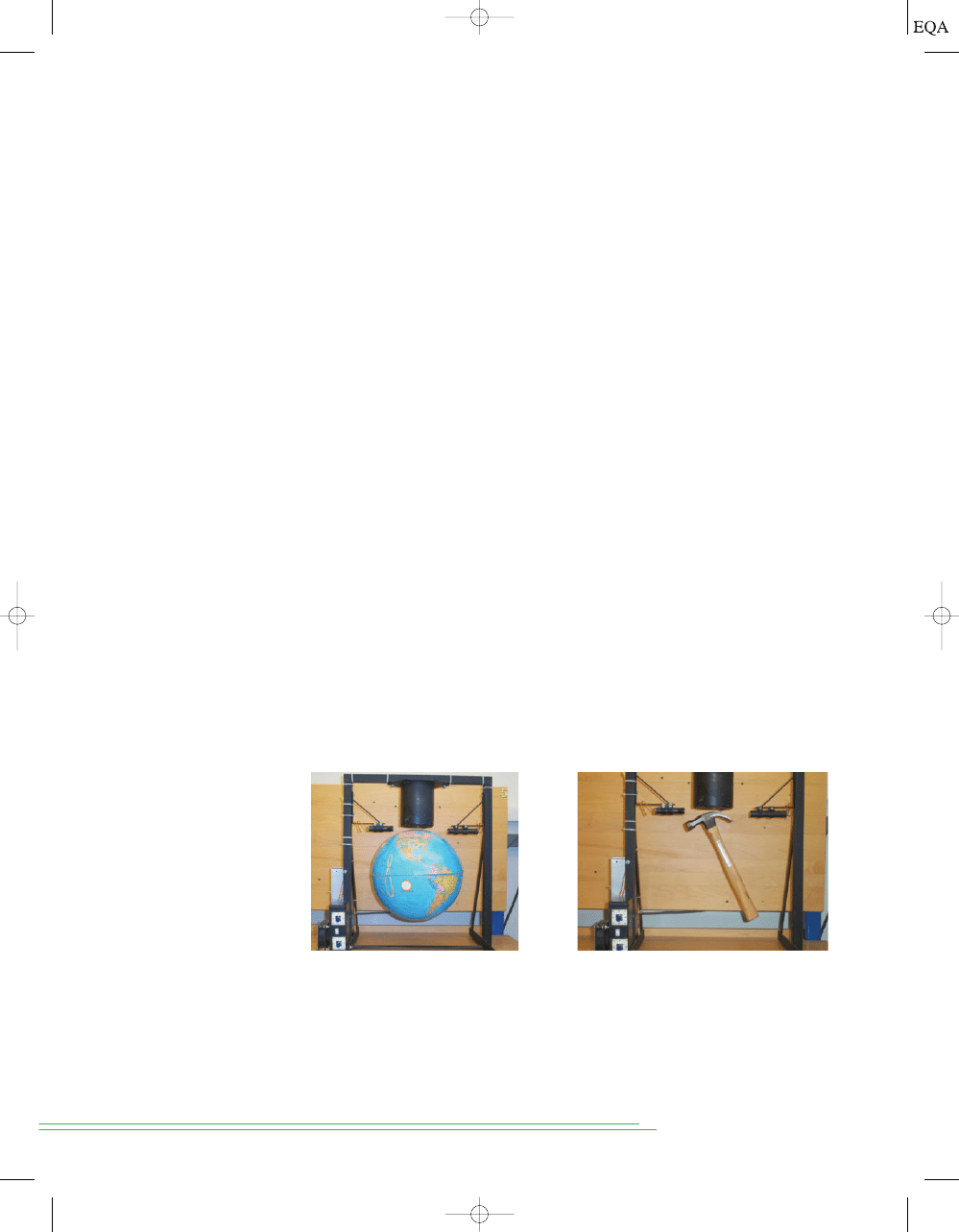
There are situations, however, where use of analog techniques is simpler
or more economical. For example, several years ago, a colleague (Tom
Robertson) decided to create a control system demonstration for tour
groups. He planned to suspend a metallic object in a magnetic field, as shown
in Figure 1-2. An electromagnet was made by winding a coil of wire and con-
trolling the amount of current through the coil. The position of the metal ob-
ject was measured by passing an infrared light beam across the magnetic
field. As the object drew closer to the magnetic coil, it began to block the
light beam. By measuring small changes in the light level, the magnetic field
could be controlled to keep the metal object hovering and stationary, with no
strings attached. All attempts at using a microcomputer to measure these
very small changes, run the control calculations, and drive the magnet
proved to be too slow, even when using the fastest, most powerful PC avail-
able at the time. His final solution used just a couple of op-amps and a few
dollars’ worth of other components: a totally analog approach. Today we have
access to processors fast enough and measurement techniques precise
enough to accomplish this feat, but the simplest solution is still analog.
8
C
HAPTER
1/
I
NTRODUCTORY
C
ONCEPTS
It is common to see both digital and analog techniques employed within
the same system to be able to profit from the advantages of each. In these
hybrid systems, one of the most important parts of the design phase involves
FIGURE 1-2
A magnetic levitation system suspending: (a) a globe with a steel
plate inserted and (b) a hammer.
(a)
(b)
TOCCMC01_0131725793.QXD 12/16/2005 1:14 PM Page 8

determining what parts of the system are to be analog and what parts are to
be digital. The trend in most systems is to digitize the signal as early as pos-
sible and convert it back to analog as late as possible as the signals flow
through the system.
The Future Is Digital
The advances in digital technology over the past three decades have been
nothing short of phenomenal, and there is every reason to believe that more
is coming. Think of the everyday items that have changed from analog format
to digital in your lifetime. An indoor/outdoor wireless digital thermometer
can be purchased for less then $10.00. Cars have gone from having very few
electronic controls to being predominantly digitally controlled vehicles.
Digital audio has moved us to the compact disk and MP3 player. Digital
video brought the DVD. Digital home video and still cameras; digital record-
ing with systems like TiVo; digital cellular phones; and digital imaging in x-
ray, magnetic resonance imaging (MRI), and ultrasound systems in hospitals
are just a few of the applications that have been taken over by the digital
revolution. As soon as the infrastructure is in place, telephone and television
systems will go digital. The growth rate in the digital realm continues to be
staggering. Maybe your automobile is equipped with a system such as GM’s
On Star, which turns your dashboard into a hub for wireless communication,
information, and navigation. You may already be using voice commands to
send or retrieve e-mail, call for a traffic report, check on the car’s mainte-
nance needs, or just switch radio stations or CDs—all without taking your
hands off the wheel or your eyes off the road. Cars can report their exact lo-
cation in case of emergency or mechanical breakdown. In the coming years
wireless communication will continue to expand coverage to provide con-
nectivity wherever you are. Telephones will be able to receive, sort, and
maybe respond to incoming calls like a well-trained secretary. The digital tel-
evision revolution will provide not only higher definition of the picture, but
also much more flexibility in programming. You will be able to select the pro-
grams that you want to view and load them into your television’s memory, al-
lowing you to pause or replay scenes at your convenience, very much like
viewing a DVD today. As virtual reality continues to improve, you will be
able to interact with the subject matter you are studying. This may not sound
exciting when studying electronics, but imagine studying history from the
standpoint of being a participant, or learning proper techniques for every-
thing from athletics to surgery through simulations based on your actual
performance.
Digital technology will continue its high-speed incursion into current ar-
eas of our lives as well as break new ground in ways we may never have con-
sidered. These applications (and many more) are based on the principles
presented in this text. The software tools to develop complex systems are con-
stantly being upgraded and are available to anyone over the Web. We will
study the technical underpinnings necessary to communicate with any of
these tools, and prepare you for a fascinating and rewarding career.
S
ECTION
1-2/
D
IGITAL AND
A
NALOG
S
YSTEMS
9
REVIEW QUESTIONS
1. What are the advantages of digital techniques over analog?
2. What is the chief limitation to the use of digital techniques?
TOCCMC01_0131725793.QXD 12/16/2005 1:14 PM Page 9
1-3
DIGITAL NUMBER SYSTEMS
Many number systems are in use in digital technology. The most common are
the decimal, binary, octal, and hexadecimal systems. The decimal system is
clearly the most familiar to us because it is a tool that we use every day.
Examining some of its characteristics will help us to understand the other
systems better.
Decimal System
The decimal system is composed of
10 numerals or symbols. These 10 symbols
are 0, 1, 2, 3, 4, 5, 6, 7, 8, 9; using these symbols as
digits of a number, we can ex-
press any quantity. The decimal system, also called the
base-10 system because
it has 10 digits, has evolved naturally as a result of the fact that people have 10
fingers. In fact, the word
digit is derived from the Latin word for “finger.”
The decimal system is a
positional-value system in which the value of a
digit depends on its position. For example, consider the decimal number 453.
We know that the digit 4 actually represents 4
hundreds, the 5 represents 5
tens, and the 3 represents 3 units. In essence, the 4 carries the most weight of
the three digits; it is referred to as the
most significant digit (MSD). The 3 car-
ries the least weight and is called the
least significant digit (LSD).
Consider another example, 27.35. This number is actually equal to 2 tens
plus 7 units plus 3 tenths plus 5 hundredths, or 2
10 7 1 3 0.1
5
0.01. The decimal point is used to separate the integer and fractional
parts of the number.
More rigorously, the various positions relative to the decimal point carry
weights that can be expressed as powers of 10. This is illustrated in Figure 1-3,
where the number 2745.214 is represented. The decimal point separates the
positive powers of 10 from the negative powers. The number 2745.214 is thus
equal to
+
(2 * 10
-
1
) + (1 * 10
-
2
) + (4 * 10
-
3
)
(2 * 10
+
3
) + (7 * 10
+
2
) + (4 * 10
1
) + (5 * 10
0
)
10
C
HAPTER
1/
I
NTRODUCTORY
C
ONCEPTS
10
3
10
2
2 7 4 5 . 2 1 4
10
1
10
0
10
–3
10
–2
10
–1
Positional values
(weights)
Decimal
point
MSD
LSD
FIGURE 1-3
Decimal
position values as powers
of 10.
In general, any number is simply the sum of the products of each digit value
and its positional value.
Decimal Counting
When counting in the decimal system, we start with 0 in the units position
and take each symbol (digit) in progression until we reach 9. Then we add a
1 to the next higher position and start over with 0 in the first position (see
TOCCMC01_0131725793.QXD 11/26/05 12:49 AM Page 10
It is important to note that in decimal counting, the units position (LSD)
changes upward with each step in the count, the tens position changes up-
ward every 10 steps in the count, the hundreds position changes upward
every 100 steps in the count, and so on.
Another characteristic of the decimal system is that using only two deci-
mal places, we can count through
different numbers (0 to 99).* With
three places we can count through 1000 numbers (0 to 999), and so on. In gen-
eral, with
N places or digits, we can count through 10
N
different numbers, start-
ing with and including zero. The largest number will always be
Binary System
Unfortunately, the decimal number system does not lend itself to convenient
implementation in digital systems. For example, it is very difficult to design
electronic equipment so that it can work with 10 different voltage levels
(each one representing one decimal character, 0 through 9). On the other
hand, it is very easy to design simple, accurate electronic circuits that oper-
ate with only two voltage levels. For this reason, almost every digital system
uses the binary (base-2) number system as the basic number system of its
operations. Other number systems are often used to interpret or represent
binary quantities for the convenience of the people who work with and use
these digital systems.
In the binary system there are only two symbols or possible digit values, 0
and 1. Even so, this base-2 system can be used to represent any quantity that
can be represented in decimal or other number systems. In general though, it
will take a greater number of binary digits to express a given quantity.
All of the statements made earlier concerning the decimal system are
equally applicable to the binary system. The binary system is also a positional-
value system, wherein each binary digit has its own value or weight expressed
as a power of 2. This is illustrated in Figure 1-5. Here, places to the left of the
10
N
-
1.
10
2
=
100
S
ECTION
1-3/
D
IGITAL
N
UMBER
S
YSTEMS
11
*Zero is counted as a number.
0
1
2
3
4
5
6
7
8
9
10
11
12
13
14
15
16
17
18
19
20
21
22
23
24
25
26
27
28
29
30
99
100
101
102
103
199
200
999
1000
FIGURE 1-4
Decimal
counting.
Figure 1-4). This process continues until the count of 99 is reached. Then we
add a 1 to the third position and start over with 0s in the first two positions.
The same pattern is followed continuously as high as we wish to count.
TOCCMC01_0131725793.QXD 11/26/05 12:49 AM Page 11
binary point (counterpart of the decimal point) are positive powers of 2, and
places to the right are negative powers of 2. The number 1011.101 is shown rep-
resented in the figure. To find its equivalent in the decimal system, we simply
take the sum of the products of each digit value (0 or 1) and its positional value:
Notice in the preceding operation that subscripts (2 and 10) were used to in-
dicate the base in which the particular number is expressed. This convention
is used to avoid confusion whenever more than one number system is being
employed.
In the binary system, the term
binary digit is often abbreviated to the
term bit, which we will use from now on. Thus, in the number expressed in
Figure 1-5 there are four bits to the left of the binary point, representing the
integer part of the number, and three bits to the right of the binary point, rep-
resenting the fractional part. The most significant bit (MSB) is the leftmost
bit (largest weight). The least significant bit (LSB) is the rightmost bit (small-
est weight). These are indicated in Figure 1-5. Here, the MSB has a weight of
2
3
; the LSB has a weight of
Binary Counting
When we deal with binary numbers, we will usually be restricted to a spe-
cific number of bits. This restriction is based on the circuitry used to repre-
sent these binary numbers. Let’s use four-bit binary numbers to illustrate the
method for counting in binary.
The sequence (shown in Figure 1-6) begins with all bits at 0; this is called
the
zero count. For each successive count, the units (2
0
) position
toggles; that
is, it changes from one binary value to the other. Each time the units bit
changes from a 1 to a 0, the twos (2
1
) position will toggle (change states). Each
time the twos position changes from 1 to 0, the fours (2
2
) position will toggle
(change states). Likewise, each time the fours position goes from 1 to 0, the
eights (2
3
) position toggles. This same process would be continued for the
higher-order bit positions if the binary number had more than four bits.
The binary counting sequence has an important characteristic, as shown in
Figure 1-6. The units bit (LSB) changes either from 0 to 1 or 1 to 0 with
each
count. The second bit (twos position) stays at 0 for two counts, then at 1 for two
counts, then at 0 for two counts, and so on. The third bit (fours position) stays
at 0 for four counts, then at 1 for four counts, and so on. The fourth bit (eights
position) stays at 0 for eight counts, then at 1 for eight counts. If we wanted to
2
-
3
.
= 11.625
10
= 8 + 0 + 2 + 1 + 0.5 + 0 + 0.125
+
(1 * 2
-
1
) + (0 * 2
-
2
) + (1 * 2
-
3
)
1011.101
2
=
(1 * 2
3
) + (0 * 2
2
) + (1 * 2
1
) + (1 * 2
0
)
12
C
HAPTER
1/
I
NTRODUCTORY
C
ONCEPTS
2
3
2
2
1 0 1 1
1 0 1
2
1
2
0
2
–3
2
–2
2
–1
Positional
values
Binary
point
MSB
LSB
FIGURE 1-5
Binary position
values as powers of 2.
TOCCMC01_0131725793.QXD 11/26/05 12:49 AM Page 12
S
ECTION
1-4/
R
EPRESENTING
B
INARY
Q
UANTITIES
13
0
1
2
3
4
5
6
7
8
9
10
11
12
13
14
15
0
0
0
0
0
0
0
0
1
1
1
1
1
1
1
1
0
0
0
0
1
1
1
1
0
0
0
0
1
1
1
1
0
0
1
1
0
0
1
1
0
0
1
1
0
0
1
1
0
1
0
1
0
1
0
1
0
1
0
1
0
1
0
1
Weights
Decimal equivalent
2
3
= 8 2
2
= 4 2
1
= 2 2
0
= 1
LSB
FIGURE 1-6
Binary
counting sequence.
REVIEW QUESTIONS
1. What is the decimal equivalent of 1101011
2
?
2. What is the next binary number following 10111
2
in the counting sequence?
3. What is the largest decimal value that can be represented using 12 bits?
1-4
REPRESENTING BINARY QUANTITIES
In digital systems, the information being processed is usually present in bi-
nary form. Binary quantities can be represented by any device that has only
two operating states or possible conditions. For example, a switch has only
two states: open or closed. We can arbitrarily let an open switch represent
EXAMPLE 1-2
What is the largest number that can be represented using eight bits?
Solution
This has been a brief introduction of the binary number system and its
relation to the decimal system. We will spend much more time on these two
systems and several others in the next chapter.
2
N
-
1 = 2
8
-
1 = 255
10
=
11111111
2
.
count further, we would add more places, and this pattern would continue with
0s and 1s alternating in groups of
For example, using a fifth binary place,
the fifth bit would alternate sixteen 0s, then sixteen 1s, and so on.
As we saw for the decimal system, it is also true for the binary system that
by using
N bits or places, we can go through 2
N
counts. For example, with two
bits we can go through
counts (00
2
through 11
2
); with four bits we can
go through
counts (0000
2
through 1111
2
); and so on. The last count
will always be all 1s and is equal to
in the decimal system. For exam-
ple, using four bits, the last count is 1111
2
=
2
4
-
1 = 15
10
.
2
N
-
1
2
4
=
16
2
2
=
4
2
N-1
.
TOCCMC01_0131725793.QXD 11/26/05 12:49 AM Page 13
binary 0 and a closed switch represent binary 1. With this assignment we can
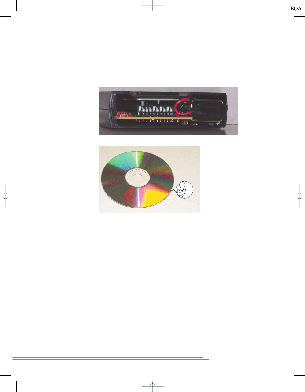
now represent any binary number. Figure 1-7(a) shows a binary code number
for a garage door opener. The small switches are set to form the binary num-
ber 1000101010. The door will open only if a matching pattern of bits is set
in the receiver and the transmitter.
14
C
HAPTER
1/
I
NTRODUCTORY
C
ONCEPTS
FIGURE 1-7
(a) Binary
code settings for a garage
door opener. (b) Digital
audio on a CD.
Another example is shown in Figure 1-7(b), where binary numbers are
stored on a CD. The inner surface (under a transparent plastic layer) is
coated with a highly reflective aluminum layer. Holes are burned through
this reflective coating to form “pits” that do not reflect light the same as the
unburned areas. The areas where the pits are burned are considered “1” and
the reflective areas are “0.”
There are numerous other devices that have only two operating states or
can be operated in two extreme conditions. Among these are: light bulb
(bright or dark), diode (conducting or nonconducting), electromagnet (ener-
gized or deenergized), transistor (cut off or saturated), photocell (illumi-
nated or dark), thermostat (open or closed), mechanical clutch (engaged or
disengaged), and spot on a magnetic disk (magnetized or demagnetized).
In electronic digital systems, binary information is represented by voltages
(or currents) that are present at the inputs and outputs of the various circuits.
Typically, the binary 0 and 1 are represented by two nominal voltage levels. For
example, zero volts (0 V) might represent binary 0, and
5 V might represent
binary 1. In actuality, because of circuit variations, the 0 and 1 would be rep-
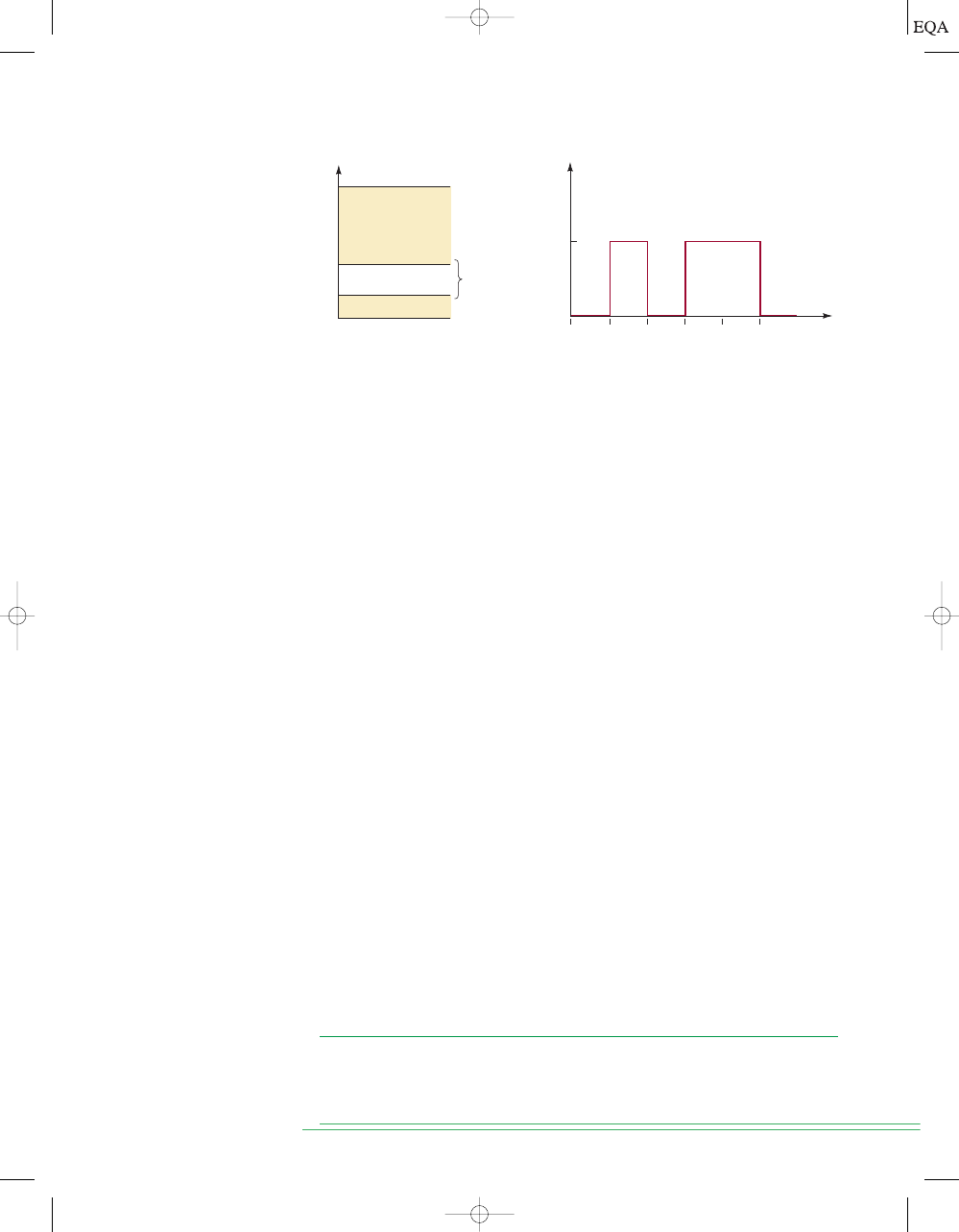
resented by voltage ranges. This is illustrated in Figure 1-8(a), where any volt-
age between 0 and 0.8 V represents a 0 and any voltage between 2 and 5 V
represents a 1. All input and output signals will normally fall within one of
these ranges, except during transitions from one level to another.
We can now see another significant difference between digital and ana-
log systems. In digital systems, the exact value of a voltage
is not important;
(a)
(b)
TOCCMC01_0131725793.QXD 12/22/2005 9:11 AM Page 14
S
ECTION
1-5/
D
IGITAL
C
IRCUITS
/L
OGIC
C
IRCUITS
15
Not
used
(a)
5 V
2 V
0.8 V
0 V
(b)
Volts
4 V
0 V
t
1
0
1
0
Binary 1
Binary 0
t
0
t
1
t
2
t
3
t
4
t
5
Invalid
voltages
FIGURE 1-8
(a) Typical voltage assignments in digital system; (b) typical digital
signal timing diagram.
for example, for the voltage assignments of Figure 1-8(a), a voltage of 3.6 V
means the same as a voltage of 4.3 V. In analog systems, the exact value of a
voltage
is important. For instance, if the analog voltage is proportional to the
temperature measured by a transducer, the 3.6 V would represent a different
temperature than would 4.3 V. In other words, the voltage value carries sig-
nificant information. This characteristic means that the design of accurate
analog circuitry is generally more difficult than that of digital circuitry be-
cause of the way in which exact voltage values are affected by variations in
component values, temperature, and noise (random voltage fluctuations).
Digital Signals and Timing Diagrams
Figure 1-8(b) shows a typical digital signal and how it varies over time. It is
actually a graph of voltage versus time
(t) and is called a timing diagram. The
horizontal time scale is marked off at regular intervals beginning at
t
0
and
proceeding to
t
1
,
t
2
, and so on. For the example timing diagram shown here,
the signal starts at 0 V (a binary 0) at time
t
0
and remains there until time
t
1
.
At
t
1
, the signal makes a rapid transition (jump) up to 4 V (a binary 1). At
t
2
,
it jumps back down to 0 V. Similar transitions occur at
t
3
and
t
5
. Note that the
signal does not change at
t
4
but stays at 4 V from
t
3
to
t
5
.
The transitions on this timing diagram are drawn as vertical lines, and so
they appear to be instantaneous, when in reality they are not. In many situ-
ations, however, the transition times are so short compared to the times be-
tween transitions that we can show them on the diagram as vertical lines. We
will encounter situations later where it will be necessary to show the transi-
tions more accurately on an expanded time scale.
Timing diagrams are used extensively to show how digital signals change
with time, and especially to show the relationship between two or more dig-
ital signals in the same circuit or system. By displaying one or more digital
signals on an
oscilloscope or logic analyzer, we can compare the signals to their
expected timing diagrams. This is a very important part of the testing and
troubleshooting procedures used in digital systems.
1-5
DIGITAL CIRCUITS/LOGIC CIRCUITS
Digital circuits are designed to produce output voltages that fall within the
prescribed 0 and 1 voltage ranges such as those defined in Figure 1-8.
Likewise, digital circuits are designed to respond predictably to input volt-
ages that are within the defined 0 and 1 ranges. What this means is that a
TOCCMC01_0131725793.QXD 11/26/05 12:49 AM Page 15
digital circuit will respond in the same way to all input voltages that fall
within the allowed 0 range; similarly, it will not distinguish between input
voltages that lie within the allowed 1 range.
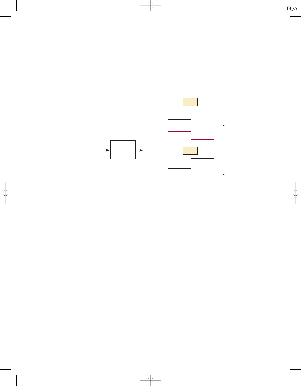
To illustrate, Figure 1-9 represents a typical digital circuit with input
v
i
and output
v
o
. The output is shown for two different input signal waveforms.
Note that
v
o
is the same for both cases because the two input waveforms,
while differing in their exact voltage levels, are at the same binary levels.
16
C
HAPTER
1/
I
NTRODUCTORY
C
ONCEPTS
Digital
circuit
v
i
v
o
0 V
0.5 V
4 V
0 V
t
3.7 V
5 V
t
Case
I
Case
II
4 V
v
i
v
o
v
i
v
o
0 V
FIGURE 1-9
A digital
circuit responds to an
input’s binary level (0 or 1)
and not to its actual
voltage.
Logic Circuits
The manner in which a digital circuit responds to an input is referred to as
the circuit’s
logic. Each type of digital circuit obeys a certain set of logic
rules. For this reason, digital circuits are also called logic circuits. We will
use both terms interchangeably throughout the text. In Chapter 3, we will
see more clearly what is meant by a circuit’s “logic.”
We will be studying all the types of logic circuits that are currently used
in digital systems. Initially, our attention will be focused only on the logical
operation that these circuits perform—that is, the relationship between the
circuit inputs and outputs. We will defer any discussion of the internal cir-
cuit operation of these logic circuits until after we have developed an un-
derstanding of their logical operation.
Digital Integrated Circuits
Almost all of the digital circuits used in modern digital systems are inte-
grated circuits (ICs). The wide variety of available logic ICs has made it pos-
sible to construct complex digital systems that are smaller and more reliable
than their discrete-component counterparts.
Several integrated-circuit fabrication technologies are used to produce dig-
ital ICs, the most common being CMOS, TTL, NMOS, and ECL. Each differs in
the type of circuitry used to provide the desired logic operation. For example,
TTL (transistor-transistor logic) uses the bipolar transistor as its main circuit el-
ement, while CMOS (complementary metal-oxide-semiconductor) uses the en-
hancement-mode MOSFET as its principal circuit element. We will learn about
the various IC technologies, their characteristics, and their relative advantages
and disadvantages after we master the basic logic circuit types.
TOCCMC01_0131725793.QXD 11/26/05 12:49 AM Page 16
1-6
PARALLEL AND SERIAL TRANSMISSION
One of the most common operations that occur in any digital system is the
transmission of information from one place to another. The information can
be transmitted over a distance as small as a fraction of an inch on the same
circuit board, or over a distance of many miles when an operator at a com-
puter terminal is communicating with a computer in another city. The infor-
mation that is transmitted is in binary form and is generally represented as
voltages at the outputs of a sending circuit that are connected to the inputs
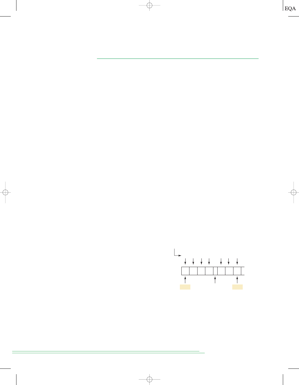
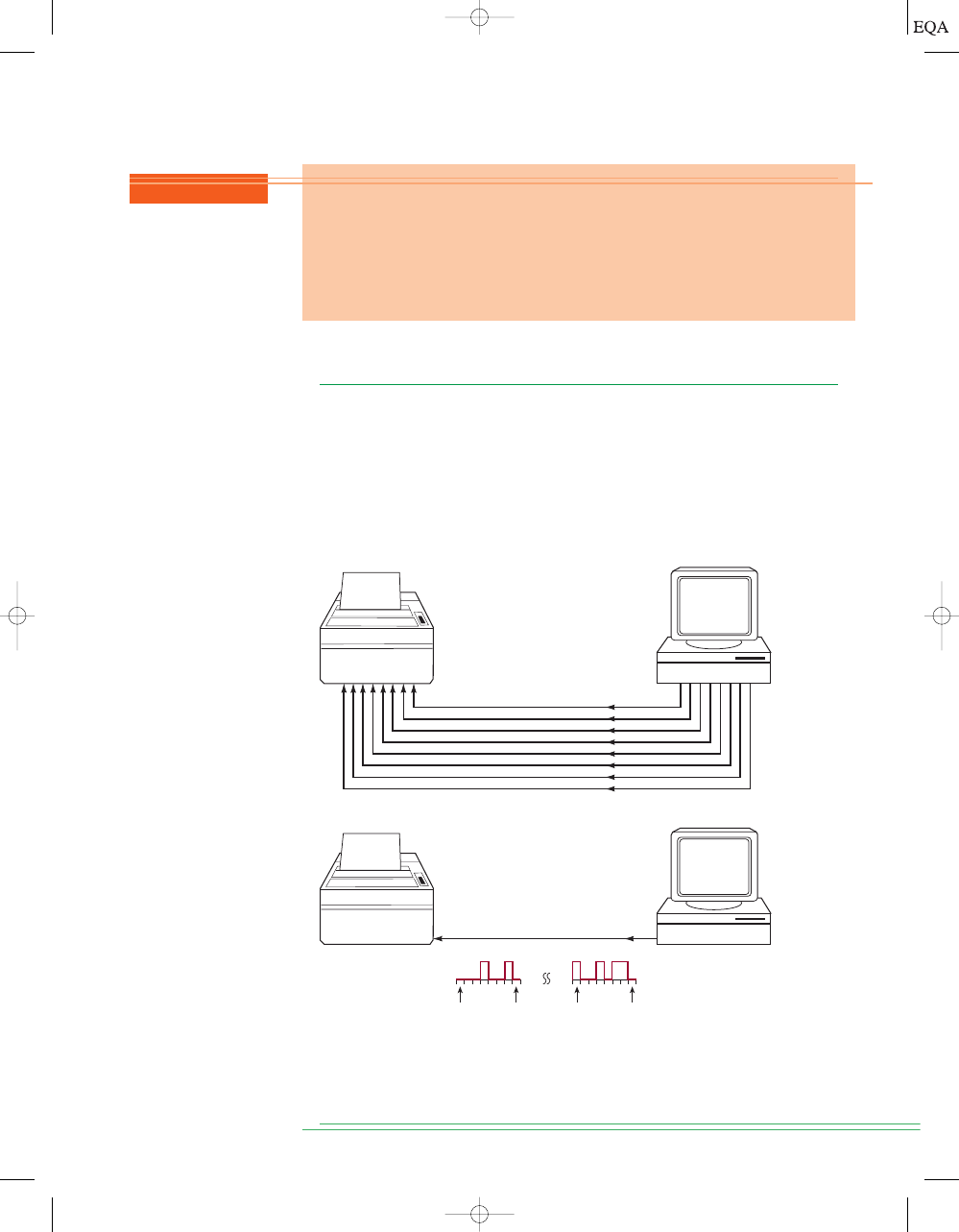
of a receiving circuit. Figure 1-10 illustrates the two basic methods for digi-
tal information transmission: parallel and serial.
S
ECTION
1-6/
P
ARALLEL AND
S
ERIAL
T
RANSMISSION
17
“H”
MSB
LSB
0
1
0
0
1
0
0
0
“i”
0
1
1
0
1
0
0
1
“H”
00010010
“i”
10010110
LSB
MSB
LSB
MSB
FIGURE 1-10
(a) Parallel
transmission uses one con-
necting line per bit, and all
bits are transmitted simul-
taneously; (b) serial trans-
mission uses only one sig-
nal line, and the individual
bits are transmitted serially
(one at a time).
Figure 1-10(a) demonstrates parallel transmission of data from a com-
puter to a printer using the parallel printer port (LPT1) of the computer. In
this scenario, assume we are trying to print the word “Hi” on the printer. The
REVIEW QUESTIONS
1.
True or false: The exact value of an input voltage is critical for a digital circuit.
2. Can a digital circuit produce the same output voltage for different input
voltage values?
3. A digital circuit is also referred to as a ________ circuit.
4. A graph that shows how one or more digital signals change with time is
called a ________.
(a)
(b)
TOCCMC01_0131725793.QXD 11/26/05 12:49 AM Page 17
binary code for “H” is 01001000 and the binary code for “i” is 01101001. Each
character (the “H” and the “i”) are made up of eight bits. Using parallel
transmission, all eight bits are sent simultaneously over eight wires. The “H”
is sent first, followed by the “i.”
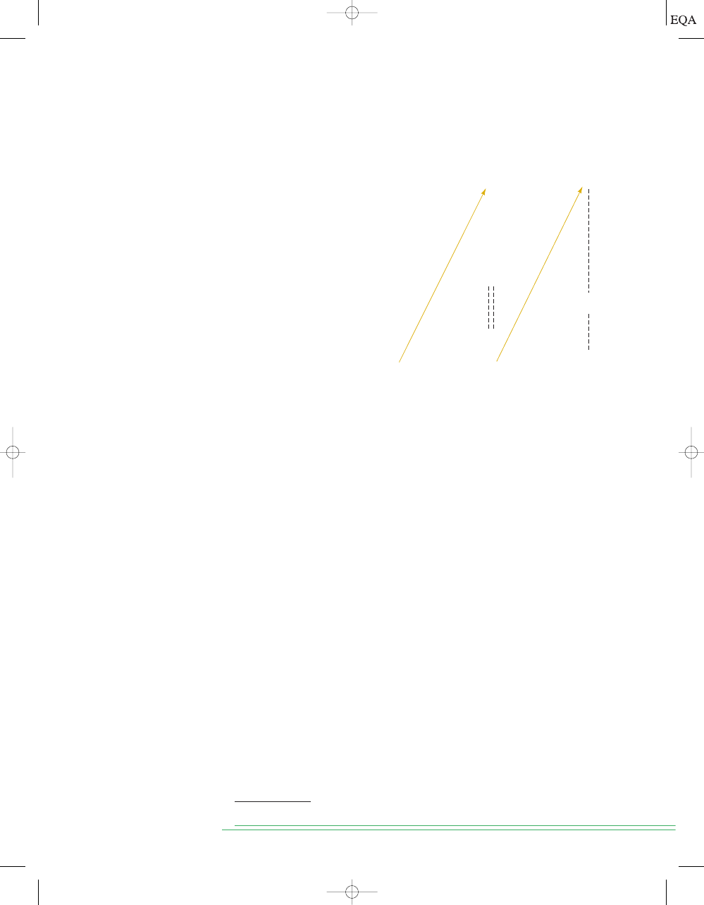
Figure 1-10(b) demonstrates serial transmission such as is employed
when using a serial COM port on your computer to send data to a modem, or
when using a USB (Universal Serial Bus) port to send data to a printer. Al-
though the details of the data format and speed of transmission are quite dif-
ferent between a COM port and a USB port, the actual data are sent in the
same way: one bit at a time over a single wire. The bits are shown in the dia-
gram as though they were actually moving down the wire in the order shown.
The least significant bit of “H” is sent first and the most significant bit of “i”
is sent last. Of course, in reality, only one bit can be on the wire at any point in
time and time is usually drawn on a graph starting at the left and advancing
to the right. This produces a graph of logic bits versus time of the serial trans-
mission called a timing diagram. Notice that in this presentation, the least
significant bit is shown on the left because it was sent first.
The principal trade-off between parallel and serial representations is one
of speed versus circuit simplicity. The transmission of binary data from one
part of a digital system to another can be done more quickly using parallel
representation because all the bits are transmitted simultaneously, while se-
rial representation transmits one bit at a time. On the other hand, parallel re-
quires more signal lines connected between the sender and the receiver of
the binary data than does serial. In other words, parallel is faster, and serial
requires fewer signal lines. This comparison between parallel and serial
methods for representing binary information will be encountered many
times in discussions throughout the text.
18
C
HAPTER
1/
I
NTRODUCTORY
C
ONCEPTS
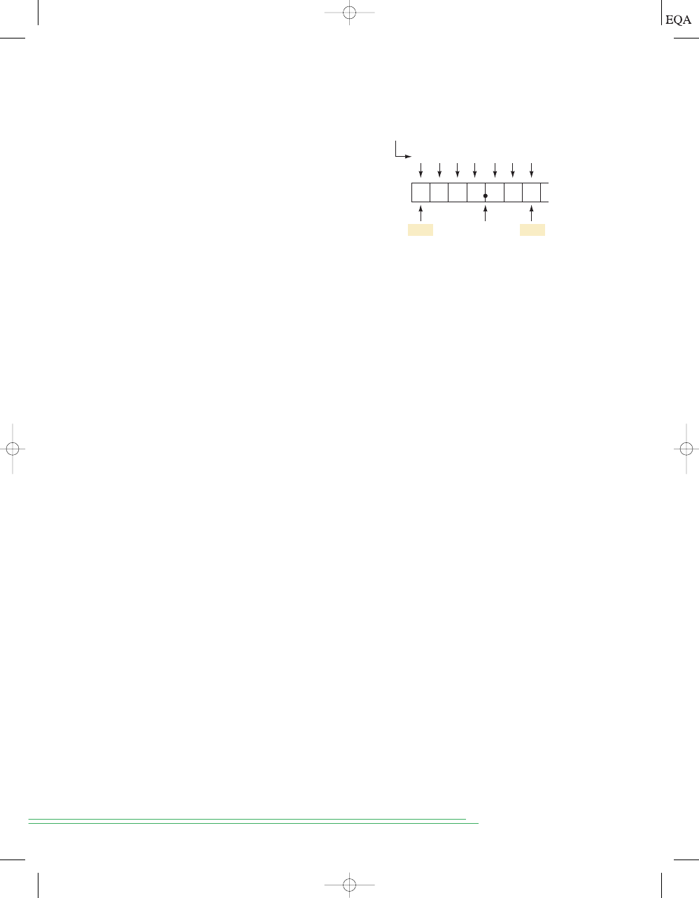
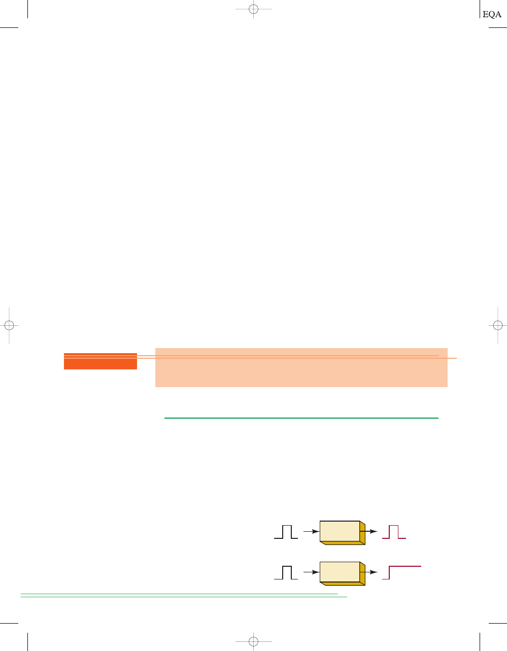
Memory
circuit
Nonmemory
circuit
FIGURE 1-11
Comparison
of nonmemory and memory
operation.
1-7
MEMORY
When an input signal is applied to most devices or circuits, the output some-
how changes in response to the input, and when the input signal is removed,
the output returns to its original state. These circuits do not exhibit the prop-
erty of
memory because their outputs revert back to normal. In digital
circuitry certain types of devices and circuits do have memory. When an input
is applied to such a circuit, the output will change its state, but it will remain
in the new state even after the input is removed. This property of retaining its
response to a momentary input is called memory. Figure 1-11 illustrates non-
memory and memory operations.
REVIEW QUESTION
1. Describe the relative advantages of parallel and serial transmission of
binary data.
TOCCMC01_0131725793.QXD 11/26/05 12:49 AM Page 18
Memory devices and circuits play an important role in digital systems be-
cause they provide a means for storing binary numbers either temporarily or
permanently, with the ability to change the stored information at any time. As
we shall see, the various memory elements include magnetic and optical types
and those that utilize electronic latching circuits (called
latches and flip-flops).
1-8
DIGITAL COMPUTERS
Digital techniques have found their way into innumerable areas of technol-
ogy, but the area of automatic digital computers is by far the most notable
and most extensive. Although digital computers affect some part of all of our
lives, it is doubtful that many of us know exactly what a computer does. In
simplest terms,
a computer is a system of hardware that performs arithmetic
operations, manipulates data (usually in binary form), and makes decisions.
For the most part, human beings can do whatever computers can do, but
computers can do it with much greater speed and accuracy, in spite of the fact
that computers perform all their calculations and operations one step at a
time. For example, a human being can take a list of 10 numbers and find their
sum all in one operation by listing the numbers one over the other and adding
them column by column. A computer, on the other hand, can add numbers
only two at a time, so that adding this same list of numbers will take nine ac-
tual addition steps. Of course, the fact that the computer requires only a few
nanoseconds per step makes up for this apparent inefficiency.
A computer is faster and more accurate than people are, but unlike most
of us, it must be given a complete set of instructions that tell it
exactly what
to do at each step of its operation. This set of instructions, called a program,
is prepared by one or more persons for each job the computer is to do. Pro-
grams are placed in the computer’s memory unit in binary-coded form, with
each instruction having a unique code. The computer takes these instruction
codes from memory
one at a time and performs the operation called for by
the code.
Major Parts of a Computer
There are several types of computer systems, but each can be broken down
into the same functional units. Each unit performs specific functions, and all
units function together to carry out the instructions given in the program.
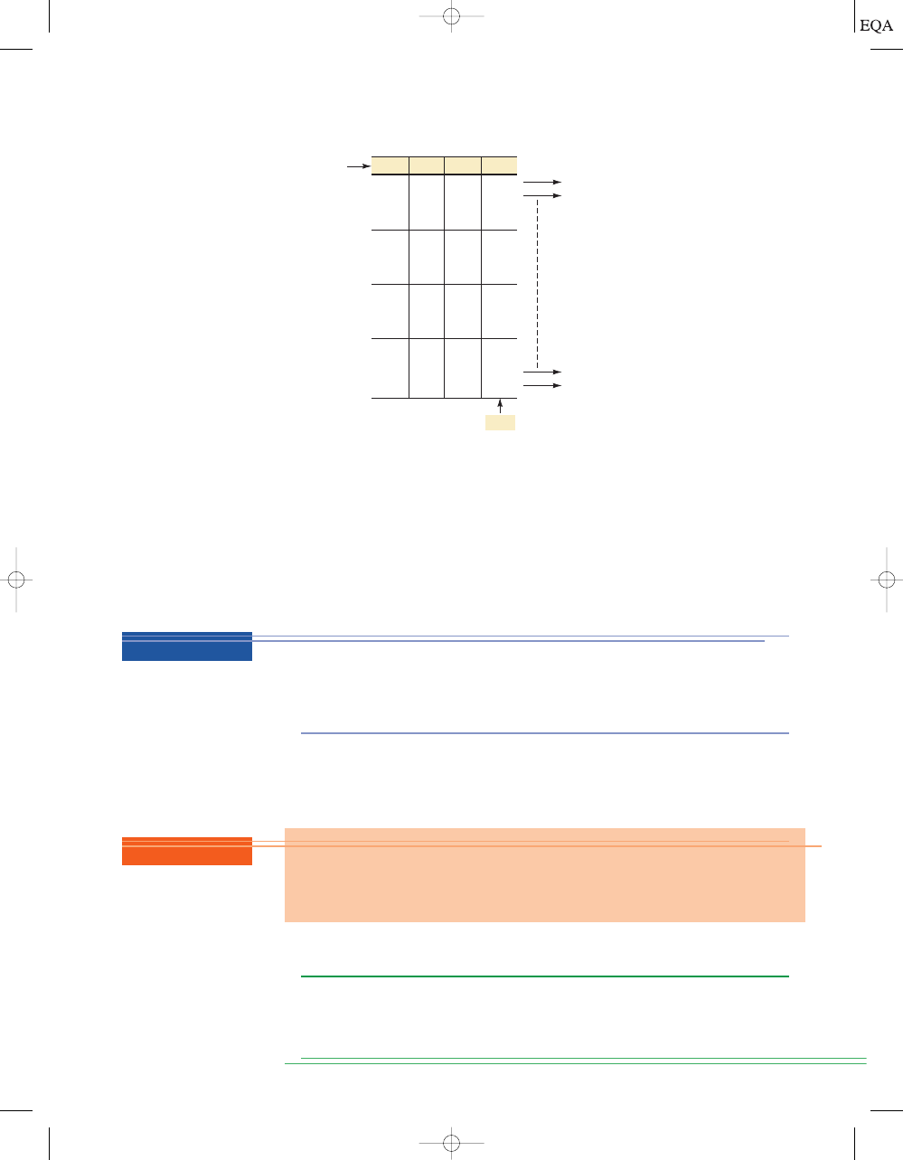
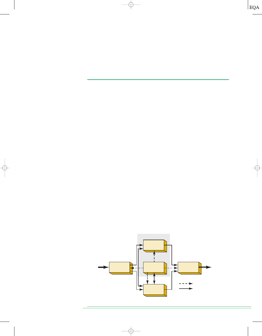
Figure 1-12 shows the five major functional parts of a digital computer and
S
ECTION
1-8/
D
IGITAL
C
OMPUTERS
19
Data,
information
Arithmetic/
logic
Input
Memory
Output
Control
Data,
information
Central Processing
Unit (CPU)
Control signals
Data or information
FIGURE 1-12
Functional diagram of a digital computer.
TOCCMC01_0131725793.QXD 11/26/05 12:49 AM Page 19

their interaction. The solid lines with arrows represent the flow of data
and information. The dashed lines with arrows represent the flow of timing
and control signals.
The major functions of each unit are:
1. Input unit. Through this unit, a complete set of instructions and data is
fed into the computer system and into the memory unit, to be stored un-
til needed. The information typically enters the input unit from a key-
board or a disk.
2. Memory unit. The memory stores the instructions and data received from
the input unit. It stores the results of arithmetic operations received from
the arithmetic unit. It also supplies information to the output unit.
3. Control unit. This unit takes instructions from the memory unit one at a
time and interprets them. It then sends appropriate signals to all the
other units to cause the specific instruction to be executed.
4. Arithmetic/logic unit. All arithmetic calculations and logical decisions
are performed in this unit, which can then send results to the memory
unit to be stored.
5. Output unit. This unit takes data from the memory unit and prints out,
displays, or otherwise presents the information to the operator (or
process, in the case of a process control computer).
Central Processing Unit (CPU)
As the diagram in Figure 1-12 shows, the control and arithmetic/logic units
are often considered as one unit, called the central processing unit (CPU).
The CPU contains all of the circuitry for fetching and interpreting instruc-
tions and for controlling and performing the various operations called for by
the instructions.
TYPES OF COMPUTERS
All computers are made up of the basic units de-
scribed above, but they can differ as to physical size, operating speed, mem-
ory capacity, and computational power, as well as other characteristics.
Computer systems are configured in many and various ways today, with many
common characteristics and distinguishing differences. Large computer sys-
tems that are permanently installed in multiple cabinets are used by corpo-
rations and universities for information technology support. Desktop
personal computers are used in our homes and offices to run useful applica-
tion programs that enhance our lives and provide communication with other
computers. Portable computers are found in PDAs and specialized comput-
ers are found in video game systems. The most prevalent form of computers
can be found performing dedicated routine tasks in appliances and systems
all around us.
Today, all but the largest of these systems utilize technology that has
evolved from the invention of the microprocessor. The microprocessor is es-
sentially a central processing unit (CPU) in an integrated circuit that can be
connected to the other blocks of a computer system. Computers that use a
microprocessor as their CPU are usually referred to as microcomputers. The
general-purpose microcomputers (e.g., PCs, PDAs, etc.) perform a variety of
tasks in a wide range of applications depending on the software (programs)
they are running. Contrast these with the dedicated computers that are do-
ing things such as operating your car’s engine, controlling your car’s antilock
braking system, or running your microwave oven. These computers cannot
be programmed by the user, but simply perform their intended control
20
C
HAPTER
1/
I
NTRODUCTORY
C
ONCEPTS
TOCCMC01_0131725793.QXD 11/26/05 12:49 AM Page 20

task: they are referred to as microcontrollers. Since these microcontrollers
are an integral part of a bigger system and serve a dedicated purpose, they
also are called
embedded controllers. Microcontrollers generally have all the
elements of a complete computer (CPU, memory, and input/output ports), all
contained on a single integrated circuit.You can find them embedded in your
kitchen appliances, entertainment equipment, photocopiers, automatic
teller machines, automated manufacturing equipment, medical instrumen-
tation, and much, much more.
So you see, even people who don’t own a PC or use one at work or school
are using microcomputers every day because so many modern consumer
electronic devices, appliances, office equipment, and much more are built
around embedded microcontrollers. If you work, play, or go to school in this
digital age, there’s no escaping it: you’ll use a microcomputer somewhere.
I
MPORTANT
T
ERMS
21
SUMMARY
1. The two basic ways of representing the numerical value of physical quan-
tities are analog (continuous) and digital (discrete).
2. Most quantities in the real world are analog, but digital techniques are
generally superior to analog techniques, and most of the predicted ad-
vances will be in the digital realm.
3. The binary number system (0 and 1) is the basic system used in digital
technology.
4. Digital or logic circuits operate on voltages that fall in prescribed ranges
that represent either a binary 0 or a binary 1.
5. The two basic ways to transfer digital information are parallel—all bits
simultaneously—and serial—one bit at a time.
6. The main parts of all computers are the input, control, memory, arith-
metic/logic, and output units.
7. The combination of the arithmetic/logic unit and the control unit makes
up the CPU (central processing unit).
8. A microcomputer usually has a CPU that is on a single chip called a
mic-
roprocessor.
9. A microcontroller is a microcomputer especially designed for dedicated
(not general-purpose) control applications.
IMPORTANT TERMS*
analog representation
digital representation
digital system
analog system
analog-to-digital
converter (ADC)
digital-to-analog
converter (DAC)
decimal system
*These terms can be found in boldface type in the chapter and are defined in the Glossary at the end
of the book. This applies to all chapters.
REVIEW QUESTIONS
1. Explain how a digital circuit that has memory differs from one that does not.
2. Name the five major functional units of a computer.
3. Which two units make up the CPU?
4. An IC chip that contains a CPU is called a _____.
TOCCMC01_0131725793.QXD 12/22/05 4:41 AM Page 21

PROBLEMS
SECTION 1-2
1-1.*Which of the following are analog quantities, and which are digital?
(a) Number of atoms in a sample of material
(b) Altitude of an aircraft
(c) Pressure in a bicycle tire
(d) Current through a speaker
(e) Timer setting on a microwave oven
1-2. Which of the following are analog quantities, and which are digital?
(a) Width of a piece of lumber
(b) The amount of time before the oven buzzer goes off
(c) The time of day displayed on a quartz watch
(d) Altitude above sea level measured on a staircase
(e) Altitude above sea level measured on a ramp
SECTION 1-3
1-3.*Convert the following binary numbers to their equivalent decimal
values.
(a) 11001
2
(b) 1001.1001
2
(c) 10011011001.10110
2
1-4. Convert the following binary numbers to decimal.
(a) 10011
2
(b) 1100.0101
(c) 10011100100.10010
1-5.*Using three bits, show the binary counting sequence from 000 to 111.
1-6. Using six bits, show the binary counting sequence from 000000 to
111111.
1-7.*What is the maximum number that we can count up to using 10 bits?
1-8. What is the maximum number that we can count up to using 14 bits?
1-9.*How many bits are needed to count up to a maximum of 511?
1-10. How many bits are needed to count up to a maximum of 63?
SECTION 1-4
1-11.*Draw the timing diagram for a digital signal that continuously alter-
nates between 0.2 V (binary 0) for 2 ms and 4.4 V (binary 1) for 4 ms.
22
C
HAPTER
1/
I
NTRODUCTORY
C
ONCEPTS
*Answers to problems marked with an asterisk can be found in the back of the text.
binary system
bit
timing diagram
digital circuits/logic
circuits
parallel transmission
serial transmission
memory
digital computer
program
input unit
memory unit
control unit
arithmetic/logic unit
output unit
central processing
unit (CPU)
microprocessor
microcomputer
microcontroller
TOCCMC01_0131725793.QXD 12/22/05 4:41 AM Page 22

1-12. Draw the timing diagram for a signal that alternates between 0.3 V
(binary 0) for 5 ms and 3.9 V (binary 1) for 2 ms.
SECTION 1-6
1-13.*Suppose that the decimal integer values from 0 to 15 are to be trans-
mitted in binary.
(a) How many lines will be needed if parallel representation is used?
(b) How many will be needed if serial representation is used?
SECTIONS 1-7 AND 1-8
1-14. How is a microprocessor different from a microcomputer?
1-15. How is a microcontroller different from a microcomputer?
ANSWERS TO SECTION REVIEW QUESTIONS
SECTION 1-1
1. Analog quantities can take on
any value over a continuous range; digital quanti-
ties can take on only
discrete values.
SECTION 1-2
1. Easier to design; easier to store information; greater accuracy and precision;
programmability; less affected by noise; higher degree of integration
2. Real-world physical quantities are analog. Digital processing takes time.
SECTION 1-3
1. 107
10
2. 11000
2
3. 4095
10
SECTION 1-5
1. False
2. Yes, provided that the two input voltages are within the same logic
level range
3. Logic
4. Timing diagram
SECTION 1-6
1. Parallel is faster; serial requires only one signal line.
SECTION 1-8
1. One that has memory will have its output changed and
remain changed in
response to a momentary change in the input signal.
2. Input, output, memory,
arithmetic/logic, control
3. Control and arithmetic/logic
4. Microprocessor
A
NSWERS TO
S
ECTION
R
EVIEW
Q
UESTIONS
23
TOCCMC01_0131725793.QXD 12/22/05 4:41 AM Page 23
Wyszukiwarka
Podobne podstrony:
Digital Systems Chapter06
Digital Systems Chapter03
Digital Systems Chapter02
Digital Systems Chapter13
Digital Systems Chapter10
digital systems
Digital Systems Cover
Digital Systems Glossary
Digital Systems IndexOfICs
Digital Systems Answers
Digital Systems Index
Digital Systems Theoremspdf
Essentials of Management Information Systems 8e Chapter08
Essentials of Management Information Systems 8e Chapter01
Essentials of Management Information Systems 8e Chapter04
Essentials of Management Information Systems 8e Chapter09
Essentials of Management Information Systems 8e Chapter07
więcej podobnych podstron