
A publication of Tyco Electronics
AMP NETCONNECT
Guide to
ISO/IEC 11801 2
nd
Edition
Including Amendment 1
February 2008
By Allan Nielsen

2
T
T
a
a
b
b
l
l
e
e
o
o
f
f
C
C
o
o
n
n
t
t
e
e
n
n
t
t
s
s
S
S
U
U
M
M
M
M
A
A
R
R
Y
Y
O
O
F
F
C
C
H
H
A
A
N
N
G
G
E
E
S
S
:
:.........................................................................................2
1
1
.
.
I
I
N
N
T
T
R
R
O
O
D
D
U
U
C
C
T
T
I
I
O
O
N
N....................................................................................................3
2
2
.
.
C
C
O
O
N
N
F
F
O
O
R
R
M
M
A
A
N
N
C
C
E
E ....................................................................................................4
3
3
.
.
S
S
T
T
R
R
U
U
C
C
T
T
U
U
R
R
E
E ...........................................................................................................5
4
4
.
.
F
F
U
U
N
N
C
C
T
T
I
I
O
O
N
N
A
A
L
L
E
E
L
L
E
E
M
M
E
E
N
N
T
T
S
S.....................................................................................7
5
5
.
.
C
C
H
H
A
A
N
N
N
N
E
E
L
L
P
P
E
E
R
R
F
F
O
O
R
R
M
M
A
A
N
N
C
C
E
E...................................................................................9
Twisted Pair Cabling (Balanced Cabling) ............................................................................9
Class D: ........................................................................................................................................9
Class E: .......................................................................................................................................10
Class E
A
: .....................................................................................................................................10
Class F: .......................................................................................................................................11
Class F
A
: .....................................................................................................................................12
Fibre Optic Cabling ....................................................................................................................13
6
6
.
.
C
C
O
O
N
N
N
N
E
E
C
C
T
T
I
I
N
N
G
G
H
H
A
A
R
R
D
D
W
W
A
A
R
R
E
E
A
A
N
N
D
D
C
C
A
A
B
B
L
L
E
E ..........................................................14
Twisted Pair Cabling (Balanced Cabling) ..........................................................................14
Fibre Optic Cabling ....................................................................................................................17
7
7
.
.
M
M
E
E
A
A
S
S
U
U
R
R
E
E
M
M
E
E
N
N
T
T
O
O
F
F
P
P
E
E
R
R
M
M
A
A
N
N
E
E
N
N
T
T
L
L
I
I
N
N
K
K
A
A
N
N
D
D
C
C
H
H
A
A
N
N
N
N
E
E
L
L
S
S..............................19
Campus Backbone or Building Backbone cabling subsystems:................................................20
Twisted Pair Cabling (Balanced Cabling).................................................................................20
Fibre Optic Cabling .....................................................................................................................20
Horizontal Cabling Subsystem: .....................................................................................................21
Twisted Pair Cabling (Balanced Cabling).................................................................................21
Fibre Optic Cabling .....................................................................................................................22
8
8
.
.
R
R
E
E
F
F
E
E
R
R
E
E
N
N
C
C
E
E
S
S
T
T
A
A
N
N
D
D
A
A
R
R
D
D
S
S ..................................................................................23
9
9
.
.
F
F
O
O
R
R
M
M
O
O
R
R
E
E
I
I
N
N
F
F
O
O
R
R
M
M
A
A
T
T
I
I
O
O
N
N ...............................................................................26
S
S
u
u
m
m
m
m
a
a
r
r
y
y
o
o
f
f
c
c
h
h
a
a
n
n
g
g
e
e
s
s
:
:
•
Addition of Classes E
A
and F
A
to meet requirements from IEEE 802.3an 10GBASE-T
•
Change of conformance clause to reflect that the new Classes E
A
and F
A
only can be verified as
channels, until amendment 2 have been published
•
Change of naming for ELFEXT to Attenuation to Crosstalk ratio Far end; ACR-F and also PS ACR-F
•
Change of naming for ACR to Attenuation to Crosstalk ratio Near end; ACR-N and also PS ACR-N
•
Addition of Alien (exogenous) crosstalk for Classes E
A
and F
A
.
•
Addition of minimum and maximum lengths for each segment of horizontal cabling
•
Deletion of 6.4.11 Power Capacity
•
Update of Unbalance attenuation, near-end (TCL) to make it normative up to 250 MHz for unscreened
systems
•
Addition of Unbalance attenuation, far-end (ELTCTL) for unscreened systems
•
Addition of Coupling attenuation for screened systems

3
1
1
.
.
I
I
n
n
t
t
r
r
o
o
d
d
u
u
c
c
t
t
i
i
o
o
n
n
The second edition of ISO/IEC 11801: Information technology - Generic cabling for customer
premises was released from ISO/IEC in September 2002. The first amendment to ISO/IEC
11801:2002 was approved in September 2007, and contains the new requirements for Class E
A
and
Class F
A
. The standard is at first sight very complex and not easy to understand.
This Guide is to help you to understand the key issues of the standard and to install your cabling in
accordance with ISO/IEC 11801 2
nd
Edition, including Amendment 1.
The abstract of the standard reads:
Within customer premises, the importance of the cabling infrastructure is similar to that of other
fundamental building utilities such as heating, lighting and mains power. As with other utilities,
interruptions to service can have a serious impact. Poor quality of service due to lack of design
foresight, use of inappropriate components, incorrect installation, poor administration or inadequate
support can threaten an organization’s effectiveness.
Historically, the cabling within premises comprised both application specific and multipurpose
networks. The original edition of this standard enabled a controlled migration to generic cabling and
the reduction in the use of application-specific cabling. This second edition of ISO/IEC 11801 has
been developed to reflect the increased demands and opportunities which have arisen since -- and
are partly the result of -- publication of the first edition in 1995.
The full standard can be bought at
http://www.iec.ch
or at your local national standardization office.
Please contact your local AMP NETCONNECT office for further information.

4
2
2
.
.
C
C
o
o
n
n
f
f
o
o
r
r
m
m
a
a
n
n
c
c
e
e
In order to conform to the standard you need to either:
1. Build a Channel, using connecting hardware and cable as specified by the document. E.g.
Category 6 connecting hardware measured with the correct method (De-Embedded) and
Category 6 cables in accordance with the cable document IEC 61156-5 and the additional
requirements described in ISO/IEC 11801 2
nd
Edition.
2. Build a Permanent Link, using connecting hardware and cable as specified by the document.
E.g. Category 6 connecting hardware measured with the correct method (De-Embedded) and
Category 6 cables in accordance with the cable document IEC 61156-5 and the additional
requirements described in ISO/IEC 11801 2
nd
Edition.
3. For Classes E
A
and F
A
conformance can only be achieved by option 1 above, until
Amendment 2 of ISO/IEC 11801:2002 have been published. Permanent Link cannot be
measured before component values, contained in Amendment 2, have been approved and
published.
The conformance clause of the standard is the most important clause because it shows you the
routes that you can use in order to build cabling which is compliant to the requirements of the
standard.
If you build a channel of manufacturer specific components, for instance an old manufacturer specific
Class E product line, which is not Category 6 components, but still meet the channel requirements,
then you are not in accordance with the requirements of the standard. This requirement has been
made to ensure the End-user has the optimum interface to the cabling and to ensure that
components are available from multiple sources with both mechanical and electrical compatibility.
This cannot be achieved for Classes E
A
and F
A
before component specifications have been agreed
and published, until then all systems sold as being compliant to the standard are manufacturer
specific cablings.
5
3
3
.
.
S
S
t
t
r
r
u
u
c
c
t
t
u
u
r
r
e
e
The structure of the standard is a pyramid construction, where cable connections going from central
points such as the Campus Distributor reach out to the next level of distributors. Distributors may be
combined in order to save space or equipment, so a campus distributor may also contain the function
of a building distributor or even a floor distributor.
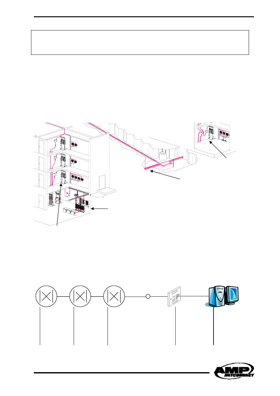
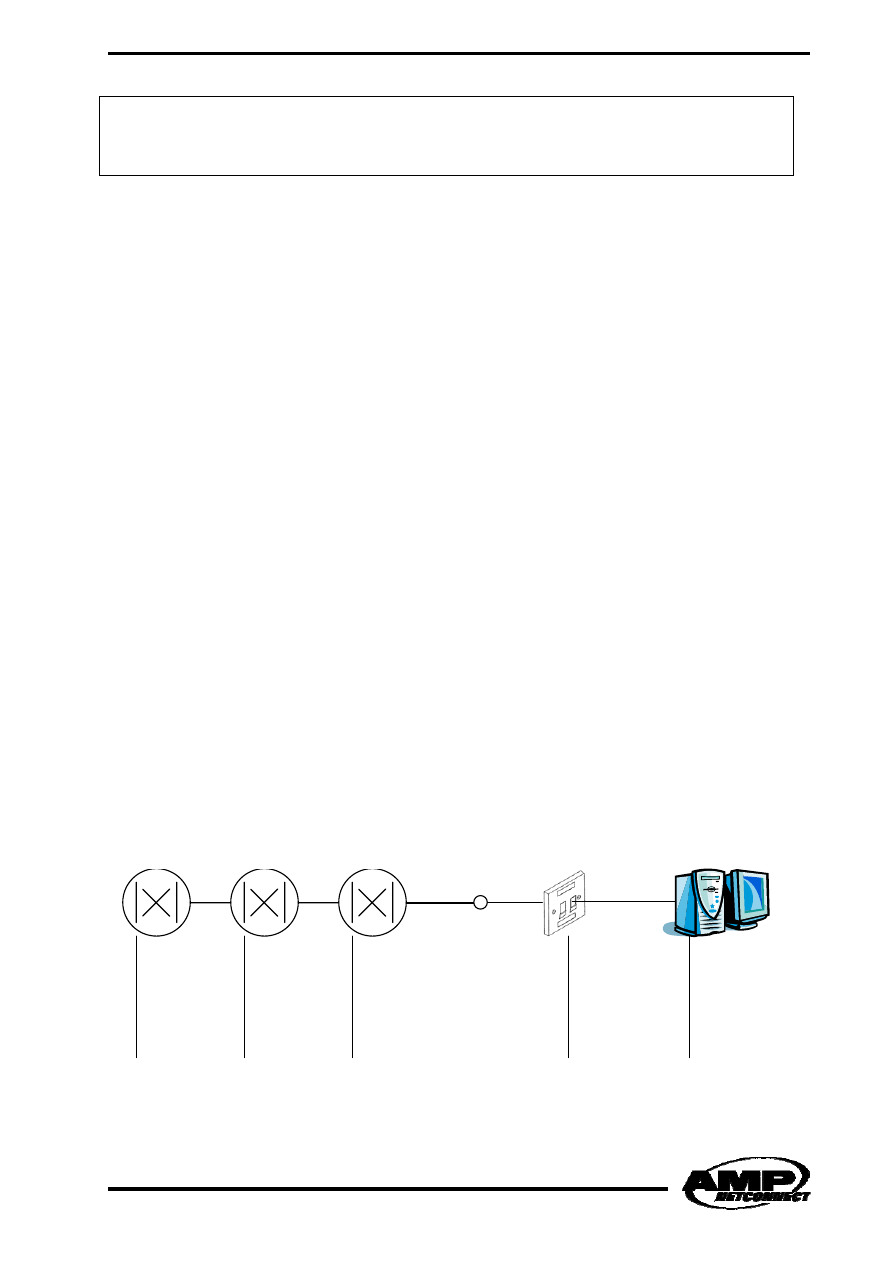
Figure 1. Structure of a cabling system
The maximum configuration of the structure is shown in figure 2.
Figure 2. Maximum configuration
Campus
Campus Backbone
Building Distributor
Floor Distributor
Campus Distributor
Building Distributor
Floor Distributor
Consolidation
Point
Telecommunication
Outlet
Campus Backbone
cabling subsystem
Building Backbone
cabling subsystem
Horizontal cabling subsystem
Work Area Cabling
6
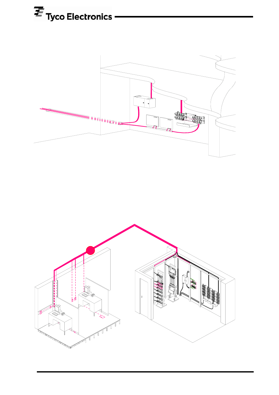
One overlooked element that always needs to be included is the Building Entrance Facilities, to
separate outside cables from inside cables. This is in order to meet local fire regulations and to serve
as a point of transient protection.
Figure 3. Building Entrance Facilities
The horizontal subsystem consists of the Floor Distributor and an optional Consolidation Point
together with the Telecommunication Outlet. The Telecommunication Outlet shall be of a Categorized
type of connecting hardware in order to be conformant to the standard. If other interfaces are
installed, the cabling is outside the specifications of the standard and consequently a manufacturer
specific cabling.
Figure 4. Horizontal Cabling
Consolidation Point
Floor Distributor

7
4
4
.
.
F
F
u
u
n
n
c
c
t
t
i
i
o
o
n
n
a
a
l
l
E
E
l
l
e
e
m
m
e
e
n
n
t
t
s
s
The standard is divided into several functional elements, which all have a function. Not all functional
elements are needed to form a generic cabling structure, but the most basic ones must always be
there; that is the Floor distributor and the Telecommunication Outlet which form the simplest
implementation of the horizontal cabling subsystem.
The functional elements of a generic cabling system are as follows:
1. Campus Distributor, which is the central point from where the campus backbone fans out,
this can either be a single wiring closet, multiple wiring closets, a room or it can be combined
with a building distributor. It is not recommended to combine a floor distributor with a
campus distributor since it would create an unwanted structure.
2. Campus Backbone Cable, which is the communication cable including connecting hardware at
both ends and jumpers or cords at the campus distributor, that connects the campus
distributor with the building distributor; it can either be copper or fibre optic. If the cable is
routed outside the building, it is always recommended to use fibre optic cables due to the risk
of transients caused by lightning. Remember that all transients / lightnings are routed
towards ground which is the medium which also contains our communication cables. Any
cabling and connecting hardware in the building entrance facilities are included in the
Campus Backbone Cable.
3. Building distributor, which is the central point in a building from where the building backbone
fans out, is either a single wiring closet, multiple closets, a room or it can be combined with a
floor distributor.
4. Building Backbone Cable, which is the communication cable including connecting hardware at
both ends and jumpers or patch cords in the building distributor, connects the building
distributor with the floor distributor; it can either be copper or fibre optic.
5. Floor Distributor, which is the central point at a floor from where the horizontal cabling fans
out, is either a single wiring closet, multiple closets or a room.
6. Horizontal Cable, which is the communication cable including connecting hardware at both
ends and jumpers or patch cords in the floor distributor, connects the floor distributor with
the telecommunication outlet, it can either be copper or fibre optic.
7. Consolidation Point, which is the central point in a room from where the consolidation point
cables fan out, is a small box or a minor wiring closet. It’s not recommended to handle more
than 12 workplaces from one consolidation point. A consolidation point shall be located at
least 15 metres (cable length) away from the floor distributor in order to minimize
disturbances from either elements.

8
8. Telecommunication Outlet, which is the interface to the generic cabling structure, can either
be mounted in a raise way, in a trunk or at the wall. The outlet should be located in a user
accessible location.
9. Multi-user Telecommunication Outlet, which is a grouping of Telecommunication Outlets; it is
not recommended that a MUTO serves more than 12 work areas and it shall be located in an
open work area so that each work area group is served by at least one MUTO.
These functional elements can be combined with both copper and fibre optic. A single work area shall
be served by at least two Telecommunications outlets; the first outlet should be 4 pair twisted pair
terminated at the connecting hardware chosen for this installation, e.g. Category 6, the second outlet
may be for two optical fibres terminated at the SC Fibre Optic connecting hardware or 4 pair twisted
pair terminated at the connecting hardware chosen for this installation.
For twisted pair installations, 2 pairs per telecommunication outlet may be used by the means of
inserts, e.g. AMP Communication Outlets with dual inserts.

9
5
5
.
.
C
C
h
h
a
a
n
n
n
n
e
e
l
l
P
P
e
e
r
r
f
f
o
o
r
r
m
m
a
a
n
n
c
c
e
e
Twisted Pair Cabling (Balanced Cabling)
The channel performance of balanced cabling shall meet or exceed the following requirements for
Class D, Class E, Class E
A
, Class F and Class F
A
channels respectively, as stated in the tables below.
All values below are derived from formulae that give a value at any frequency across the frequency
range of the channel. These formulae can be found in clause 6 of the standard document ISO/IEC
11801 2
nd
Edition, including Amendment 1.
The tables below shall be considered as informative, while the formulae in the standard are the
normative requirement.
Pair to pair NEXT, ACR-N and ACR-F are normative, but not quoted here. All power sum values are
derived from pair to pair performance.
Class D:
Frequency MHz
Attenuation
PS NEXT
PS ACR-N
PS ACR-F
Return Loss
Coupling Attenuation
PS ANEXT
PS AACR-F
Propagation delay
Delay Skew
Unbalance Attenuation
MHz dB dB dB dB dB dB dB dB us us dB
1
4,0 60,3 56,3 54,4 17,0 NA - -
0,580
0,050
40,0
4
4,5 50,5 46,0 42,4 17,0 NA - -
0,562
0,050
40,0
10
7,2 44,0 36,8 34,4 17,0 NA - -
0,555
0,050
38,0
16
9,1 40,6 31,5 30,3 17,0 NA - -
0,553
0,050
34,9
20
10,2 39,0 28,8 28,4 17,0 NA - -
0,552
0,050
33,5
31
12,8 35,8 22,9 24,6 15,1 50,2 - - 0,550
0,050
30,5
62
18,5 30,6 12,1 18,6 12,1 44,2 - - 0,549
0,050
24,5
100
24,0 27,1 3,1 14,4 10,0 40,0 - - 0,548
0,050
20,3
10
Class E:
Frequency MHz
Attenuation
PS NEXT
PS ACR-N
PS ACR-F
Return Loss
Coupling Attenuation
PS ANEXT
PS AACR-F
Propagation delay
Delay Skew
Unbalance Attenuation
MHz dB dB dB dB dB dB dB dB us us dB
1
4,0 62,0 58,0 60,3 19,0 NA - -
0,580
0,050
40,0
4
4,2 60,5 56,4 48,2 19,0 NA - -
0,562
0,050
40,0
10
6,6 54,0 47,4 40,3 19,0 NA - -
0,555
0,050
38,0
16
8,3 50,6 42,3 36,2 18,0 NA - -
0,553
0,050
34,9
20
9,3 49,0 39,7 34,2 17,5 NA - -
0,552
0,050
33,5
31
11,7 45,8 34,1 30,4 16,5 50,2 - - 0,550
0,050
30,5
62
16,8 40,6 23,8 24,4 14,1 44,2 - - 0,549
0,050
24,5
100
21,7 37,1 15,4 20,3 12,0 40,0 - - 0,548
0,050
20,3
125
24,5 35,4 10,9 18,3 11,0 38,1 - - 0,547
0,050
18,4
155
27,6 33,8 6,2 16,5 10,1 36,2 - - 0,547
0,050
16,5
175
29,5 32,9 3,4 15,4 9,6 35,1 - - 0,547
0,050
15,4
200
31,7 31,9 0,1 14,2 9,0 34,0 - - 0,547
0,050
14,3
250
35,9 30,2 -5,8 12,3 8,0 32,0 - - 0,546
0,050
12,3
Class E
A
:
Frequency MHz
Attenuation
PS NEXT
PS ACR-N
PS ACR-F
Return Loss
Coupling Attenuation
PS ANEXT
PS AACR-F
Propagation delay
Delay Skew
Unbalance Attenuation
MHz dB dB dB dB dB dB dB dB us us dB
1
4,0 62,0 58,0 60,3 19,0 NA 67,0 67,0 0,580 0,050 40,0
4
4,2 60,5 56,4 48,2 19,0 NA 67,0 65,0 0,562 0,050 40,0
10
6,5 54,0 47,5 40,3 19,0 NA 67,0 57,0 0,555 0,050 38,0
16
8,2 50,6 42,4 36,2 18,0 NA 67,0 52,9 0,553 0,050 34,9
20
9,2 49,0 39,8 34,2 17,5 NA 67,0 51,0 0,552 0,050 33,5
31
11,4 45,8 34,3 30,4 16,5 50,2 65,1 47,2 0,550
0,050 30,5
62
16,3 40,6 24,3 24,4 14,1 44,2 62,1 41,2 0,549
0,050 24,5
100
20,9 37,1 16,2 20,3 12,0 40,0 60,0 37,0 0,548
0,050 20,3
125
23,5 35,4 11,9 18,3 11,0 38,1 58,5 35,1 0,547
0,050 18,4
155
26,3 33,8 7,5 16,5 10,1 36,2 57,1 33,2 0,547
0,050 16,5
175
28,0 32,9 4,8 15,4 9,6 35,1 56,4 32,1 0,547
0,050 15,4
200
30,1 31,9 1,8 14,2 9,0 34,0 55,5 31,0 0,547
0,050 14,3
250
33,9 30,2 -3,7 12,3 8,0 32,0 54,0 29,0 0,546
0,050 12,3
300
37,4 28,8 -8,6 10,7 7,2 30,5 52,8 27,5 0,546
0,050 FFS
400
43,7 26,6 -17,1 8,2 6,0 28,0 51,0 25,0 0,546
0,050 FFS
500
49,3 24,8 -24,5 6,3 6,0 26,0 49,5 23,0 0,546
0,050 FFS

11
Class F:
Frequency MHz
Attenuation
PS NEXT
PS ACR-N
PS ACR-F
Return Loss
Coupling Attenuation
PS ANEXT
PS AACR-F
Propagation delay
Delay Skew
Unbalance Attenuation
MHz dB dB dB dB dB dB dB dB us us dB
1
4,0 62,0 58,0 62,0 19,0 NA - -
0,580
0,030
40,0
4
4,1 62,0 57,9 62,0 19,0 NA - -
0,562
0,030
40,0
10
6,4 62,0 55,6 57,8 19,0 NA - -
0,555
0,030
38,0
16
8,1 62,0 53,9 54,5 18,0 NA - -
0,553
0,030
34,9
20
9,1 62,0 52,9 52,9 17,5 NA - -
0,552
0,030
33,5
31
11,3 62,0 50,7 49,8 16,5 50,2 - - 0,550
0,030
30,5
62
16,2 62,0 45,8 44,9 14,1 44,2 - - 0,549
0,030
24,5
100
20,8 59,9 39,1 41,4 12,0 40,0 - - 0,548
0,030
20,3
125
23,4 58,4 35,0 39,8 11,0 38,1 - - 0,547
0,030
18,4
155
26,2 57,0 30,8 38,3 10,1 36,2 - - 0,547
0,030
16,5
175
27,9 56,2 28,3 37,4 9,6 35,1 - - 0,547
0,030
15,4
200
30,0 55,3 25,4 36,4 9,0 34,0 - - 0,547
0,030
14,3
250
33,8 53,9 20,1 34,8 8,0 32,0 - - 0,546
0,030
12,3
300
37,3 52,7 15,4 33,4 8,0 30,5 - - 0,546
0,030
FFS
400
43,6 50,8 7,2 31,3 8,0 28,0 - - 0,546
0,030
FFS
500
49,3 49,4 0,1 29,6 8,0 26,0 - - 0,546
0,030
FFS
600
54,6 48,2 -6,4 28,3 8,0 24,4 - - 0,545
0,030
FFS
12
Class F
A
:
Frequency MHz
Attenuation
PS NEXT
PS ACR-N
PS ACR-F
Return Loss
Coupling Attenuation
PS ANEXT
PS AACR-F
Propagation delay
Delay Skew
Unbalance Attenuation
MHz dB dB dB dB dB dB dB dB us us dB
1
4,0 62,0 58,0 62,0 19,0 NA 67,0 67,0 0,580 0,030 40,0
4
4,1 62,0 57,9 62,0 19,0 NA 67,0 67,0 0,562 0,030 40,0
10
6,4 62,0 55,6 62,0 19,0 NA 67,0 67,0 0,555 0,030 38,0
16
8,0 62,0 54,0 60,3 18,0 NA 67,0 67,0 0,553 0,030 34,9
20
9,0 62,0 53,0 58,4 17,5 NA 67,0 66,0 0,552 0,030 33,5
31
11,2 62,0 50,8 54,6 16,5 50,2 67,0 62,2 0,550
0,030 30,5
62
15,9 62,0 46,1 48,5 14,1 44,2 67,0 56,2 0,549
0,030 24,5
100
20,3 62,0 41,7 44,4 12,0 40,0 67,0 52,0 0,548
0,030 20,3
125
22,7 61,7 39,0 42,5 11,0 38,1 67,0 50,1 0,547
0,030 18,4
155
25,4 60,0 34,6 40,6 10,1 36,2 67,0 48,2 0,547
0,030 16,5
175
27,0 59,0 32,0 39,5 9,6 35,1 67,0 47,1 0,547
0,030 15,4
200
28,9 57,9 29,0 38,4 9,0 34,0 67,0 46,0 0,547
0,030 14,3
250
32,5 56,1 23,7 36,4 8,0 32,0 67,0 44,0 0,546
0,030 12,3
300
35,7 54,7 19,0 34,8 8,0 30,5 67,0 42,5 0,546
0,030 FFS
400
41,5 52,4 10,9 32,3 8,0 28,0 66,0 40,0 0,546
0,030 FFS
500
46,7 50,6 3,9 30,4 8,0 26,0 64,5 38,0 0,546
0,030 FFS
600
51,4 49,1 -2,3 28,8 8,0 24,4 63,3 36,4 0,545
0,030 FFS
1000
67,6 44,9 -22,6 24,4 6,0 20,0 60,0 32,0 0,545
0,030 FFS
All channels are based on the maximum of 4 set of connectors.
In amendment 1 of ISO/IEC 11801 2
nd
Edition a minimum length has been added to ensure Alien
Crosstalk performance for balanced cabling channels:
Segment Minimum
Maximum
Floor Distributor to Consolidation Point
15
85
Consolidation Point to Telecommunication Outlet
5
-
Floor Distributor to Telecommunication Outlet
15
90
Work area cord
1
2
5
Patch cord
2
-
Equipment cord
2
2
5
All cords
-
10
Note 1: If there is no Consolidation Point, the minimum length of the work area cord is 1 metre.
Note 2: If there is no cross-connect, the minimum length of the equipment cord is 1 metre.
13
Please consult the manufacturer of the cabling system for shorter length support, e.g. this can be
done with an AMP NETCONNECT XG screened cabling system, supporting link lengths down to 5
metres.
If a screened system us used for Class E
A
and Class F
A
, then Alien Crosstalk is met by design; this
means that channel verification of Alien Crosstalk (PS ANEXT and PS AACR-F) is unnecessary, due to
the superior performance of shielded systems.
Unscreened Class E
A
channels needs to have Alien Crosstalk verified in order to meet the standard,
regardless of manufacturer`s warranty. This can be achieved by complex measurement technologies
developed by manufacturers of field testing equipment.
Fibre Optic Cabling
The channel performance of fibre optic cabling shall exceed the following requirements for OF-300,
OF-500 and OF-2000 channels respectively, as stated in the table below.
Channel Attenuation
dB
Multimode Singlemode
Channel
850 nm
1300 nm
1310 nm
1550 nm
OF-300
2,55 1,95 1,80 1,80
OF-500
3,25 2,25 2,00 2,00
OF-2000
8,50 4,50 3,50 3,50
All channels are based on the maximum of:
• 300, 500 or 2000 metre of fibre optic cable
• 2 mated connections (1,5 dB allocation)
The three optical fibre channels are defined as:
• OF-300: A channel that supports applications over the optical fibre types referenced in the
cable clause to a minimum of 300 metres.
• OF-500: A channel that supports applications over the optical fibre types referenced in the
cable clause to a minimum of 500 metres.
• OF-2000: A channel that supports applications over the optical fibre types referenced in the
cable clause to a minimum of 2000 metres.
Care shall be taken to ensure that fibre types of different physical construction, defined as the core
and cladding diameter and numerical aperture (bandwidth), are not mixed within a channel. Mixing of
different fibre types may result in degradation of the fibre optical channel performance.

14
6
6
.
.
C
C
o
o
n
n
n
n
e
e
c
c
t
t
i
i
n
n
g
g
H
H
a
a
r
r
d
d
w
w
a
a
r
r
e
e
a
a
n
n
d
d
C
C
a
a
b
b
l
l
e
e
Twisted Pair Cabling (Balanced Cabling)
Connecting hardware and Cable are the building blocks that you use to create your cabling. In the
standard these are called components. The choice of components is important to both the installer
and the end user, not only because of the price and delivery performance of different manufacturers,
but also because of the total cabling channel performance.
In ISO/IEC 11801 2
nd
Edition you can find the following text:
Horizontal cabling - Component choice
The selection of balanced cabling components will be determined by the class of applications to be
supported. Refer to Annex F for guidance.
Using the configurations of 7.2.2.2:
• Category 5 components provide Class D balanced cabling performance;
• Category 6 components provide Class E balanced cabling performance;
• Category 6
A
components provide Class E
A
balanced cabling performance;
• Category 7 components provide Class F balanced cabling performance;
• Category 7
A
components provide Class F
A
balanced cabling performance.
Cables and connecting hardware of different categories may be mixed within a channel; however the
resultant cabling performance will be determined by the category of the lowest performing
component.”
Class E
A
and Class F
A
channels are, until Amendment 2 of ISO/IEC 11801 2
nd
Edition is published,
manufacturer specific. Category 6
A
and Category 7
A
connecting hardware and cable specifications are
subject to new measurement methods for components, and performance are expected to be
published during 2009.
Only channel performance of Class E
A
and Class F
A
can be verified in accordance with this standard,
until Amendment 2 of ISO/IEC 11801 2
nd
Edition is published.

15
The minimum performance for connecting hardware can be found in:
Standard Category
Comment
IEC 60603-7-2
Category 5 UTP
Also known as TIA/EIA Category 5 Enhanced
IEC 60603-7-3
Category 5 STP
Also known as TIA/EIA Category 5 Enhanced
IEC 60603-7-4
Category 6 UTP
IEC 60603-7-41
Category 6
A
UTP
Not published yet, expected during 2009.
IEC 60603-7-5
Category 6 STP
IEC 60603-7-51
Category 6
A
STP
Not published yet, expected during 2009.
IEC 60603-7-7
Category 7 STP
RJ45 interface with switch function to alternate pair
assignment
IEC 60603-7-71
Category 7
A
STP
Not published yet, expected during 2009.
IEC 61076-3-104
Category 7 STP
Category 7
A
STP
Alternative High Performance interface, specified as 1000
MHz connector in its current version.
Category 5 and 6 standards have the De-Embedded test method as the only test method which can
qualify the connecting hardware. Please see AMP NETCONNECT white paper on that subject for
further information.
Category 6A and Category 7A standards are subject to new measurement methods, using direct
probing and Re-Embedding techniques to verify component performance.
In the above standards the specification requires separate values for both the Modular Plug and the
Modular Jack in order to have compatibility between different manufactures of connecting hardware.
E.g. it should be possible to mate a Plug from AMP NETCONNECT with any other manufacturer of
Jacks (Sockets) and still meet the requirements. This is not valid for Category 6
A
and Category 7
A
connecting hardware, until the component and measurement standards have been published.
For twisted Pair cabling, the only place where a standardized interface is required is at the
Telecommunication Outlet. At any other point the user is free to choose any other interface meeting
the transmission characteristics of the standardized interface; this is explained in detail in Annex C of
ISO/IEC 11801 2
nd
Edition. This requires more test equipment than just a hand held tester, which
means that verification has to be validated at a laboratory, either at the manufacturer or a 3
rd
party,
before installation. The easiest implementation is to use standardized interfaces throughout the
installation.
Twisted Pair cables are referenced as balanced cables in the standard, due to the possibility of
making the cables with a quad. A quad is 4 wires which are twisted together to form a cable element,
while most cables have a pair as the cable element.

16
The requirements for cable have to meet the specified IEC standards together with some additional
requirements, specified in ISO/IEC 11801 2
nd
Edition. These requirements are:
Mean Characteristic Impedance:
The nominal impedance shall be 100 Ohm. The cable standards allow both 100 and 120 Ohm, but a
120 Ohm cable would make it impossible to create a channel without return loss problems.
Attenuation:
There are two types of Category 5 cables, one specified by ISO/IEC and one specified by TIA/EIA.
The difference between these two cables is a little higher attenuation on the TIA/EIA. Usage of the
TIA/EIA cable is not allowed by ISO/IEC 11801 2
nd
edition.
The minimum performance of twisted pair cables can be found in:
Standard Specification
Comment
IEC 61156-2 (2007)
Sectional Specification for multicore and symmetrical
pair/quad cables for digital communications – Horizontal
wiring
General
requirement
s
IEC 61156-3 (2007)
Sectional Specification for multicore and symmetrical
pair/quad cables for digital communications – Work area
wiring
General
requirement
s
IEC 61156-4 (2007)
Sectional Specification for multicore and symmetrical
pair/quad cables for digital communications – Riser cables
General
requirement
s
IEC 61156-5 (2007)
Symmetrical pair/quad cables for digital communications
with transmission characteristics up to 600 MHz – Part 5:
Horizontal wiring
Performance
requirement
s
IEC 61156-6 (2007)
Symmetrical pair/quad cables for digital communications
with transmission characteristics up to 600 MHz – Part 6:
Work area wiring
Performance
requirement
s

17
Fibre Optic Cabling
The minimum performance of fibre optic connecting hardware can be found in:
Standard Specification
Requirements
IEC 60874-19-1
SC Duplex Fibre Optic patch cord connector type
SC-PC (floating duplex)
Optical, mechanical
and environmental
IEC 60874-19-2
SC Duplex Fibre Optic adaptor for singlemode
fibre
Optical, mechanical
and environmental
IEC 60874-19-3
SC Duplex Fibre Optic adaptor for multimode fibre Optical, mechanical
and environmental
For Fibre Optic cabling the only place where the above standardized interface is required is at the
Telecommunication Outlet. At any other place the user is free to choose any other interface which is
standardized by IEC and meets the optical and environmental requirements of an SC Duplex
connector. Connecting hardware of the types MU, MT-RJ and LC meets these requirements.
Please note that ST connectors are not allowed by the standard any more, due to the environmental
and optical performance of this interface.
The attenuation of fibre optic connecting hardware is based on a statistical value. An example:
• If you have 200 connectors and mate them to 100 mated connectors, then you will have a
range of attenuations within the connector groups. This range will go from 0,1 to 0,75 dB
where most connections will be around 0,3 dB.
• The average attenuation will not change if you rearrange the mating of the connectors.
• One connector mated with 100 other connectors will have the attenuation range from 0,1 to
0,75 dB, but 0,3 in average.
The maximum attenuation performance of a fibre optic cable shall be:
Maximum Cable Attenuation
DB/km
OM1, OM2 and OM3 Multimode
OS1 Singlemode
Wavelength
850 nm
1300 nm
1310 nm
1550 nm
Attenuation
3,5 1,5 1,0 1,0

18
The minimum bandwidth of a fibre optic cable shall be:
Minimum modal bandwidth
MHz - km
Overfilled Launch Bandwidth
Effective Laser
Launch
Bandwidth
Wavelength
850 nm
1300 nm
850 nm
Optical fibre
type
Core diameter
in
μm
OM1
50 or 62,5
200
500
Not specified
OM2
50 or 62,5
500
500
Not specified
OM3
50 1500 500 2000
Multimode Optical fibre shall comply to the following standards:
Standard Specification
Comment
IEC 60793-2-10
Multimode fibre optic standard
type A1a equal to 50/125
μm
This standard specifies a range of
bandwidths; ISO/IEC has specified the exact
minimum values for this cable type.
IEC 60793-2-10
Multimode fibre optic standard
type A1b equal to 62,5/125
μm
This standard specifies a range of
bandwidths; ISO/IEC has specified the exact
minimum values for this cable type.
IEC 60793-2-50
Singlemode fibre optic standard
type B1 equal to 9/125
μm
Furthermore the fibre shall meet ITU-T G.652.
IEC 60794-2
Indoor mechanical and
environmental requirements
General requirements.
IEC 60794-3
Outdoor mechanical and
environmental requirements
General requirements.
19
7
7
.
.
M
M
e
e
a
a
s
s
u
u
r
r
e
e
m
m
e
e
n
n
t
t
o
o
f
f
P
P
e
e
r
r
m
m
a
a
n
n
e
e
n
n
t
t
L
L
i
i
n
n
k
k
a
a
n
n
d
d
C
C
h
h
a
a
n
n
n
n
e
e
l
l
s
s
In order to measure Permanent Links or Channels in accordance with ISO/IEC 11801 2
nd
edition, you
need to understand the building blocks that you can use, please refer to the Structure clause of this
document for further information.
The three different subsystems of a structured cabling shall be measured separately, either as
1: a Permanent Link which consists of the connecting hardware and cables that are permanent. An
example is:
• A Horizontal Link spanning from the first patch panel at the floor distributor to the
telecommunication outlet, including an optional consolidation point. Patch cords and jumpers
are not included.
• A Horizontal Link spanning from the first patch panel at the floor distributor to the
consolidation point connector. Patch cord and jumpers are not included.
Or 2: a channel which is like the above, only including patch cords and jumpers. Class E
A
and Class F
A
can only be verified as channels, until Amendment 2 of ISO/IEC 11801 2
nd
Edition have been
published.
The following examples show the different ways of implementing a Permanent Link or a Channel, in
either a backbone or a horizontal cabling subsystem:
Campus Distributor
Building Distributor
Floor Distributor
Consolidation
Point
Telecommunication
Outlet
Campus Backbone
cabling subsystem
Building Backbone
cabling subsystem
Horizontal cabling subsystem
Work Area Cabling
20
Campus Backbone or Building Backbone cabling subsystems:
Twisted Pair Cabling (Balanced Cabling)
A Channel measurement includes all patch cords and jumpers and span from the ends of the channel.
The measurement equipment limits shall be set to “ISO/IEC 11801 2
nd
Edition, Amendment 1 Class A,
Class B, Class C, Class D, Class E, Class E
A
, Class F or Class F
A
channel” settings. If applicable for the
tester, the values shall include 4 connections.
A Link does not include any patch cords and jumpers and span from the interconnect in each side of
the installed cable. When measuring backbone systems, the measurement equipment limits shall be
set to “ISO/IEC 11801 2
nd
Edition, Amendment 1 Class A, Class B, Class C, Class D, Class E or Class F
Link” settings. If applicable for the tester the values shall include 2 connections.
Fibre Optic Cabling
Channel measurement includes all patch cords and jumpers, and span from the ends of the channel.
The power budget shall include up to 4 mated connections and the given amount of installed cable
for OF-300, OF-500 or OF-2000 respectively.
A Link does not include any patch cords and jumpers, and span from the interconnect in each side of
the installed cable. When measuring backbone systems, the power budget shall include 2 mated
connections and the given amount of installed cable for OF-300, OF-500 or OF-2000 respectively.
When measuring Fibre Optic Cabling systems, a mandrel wrap shall be used on the launch fibre. The
function of a mandrel wrap is to remove any unwanted modes (light signals), in the reference cords
and in the installation, under measurement.
ISO/IEC 14763-3 specifies usage of reference connectors, which are controlled end face connectors
with a very low attenuation, when measuring fibre optic channels or links. These measurement kits
can be found in the AMP NETCONNECT product catalogue.
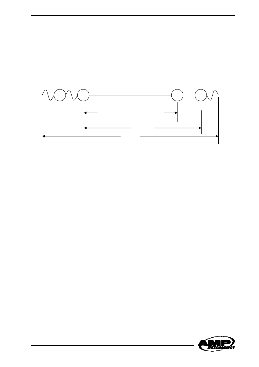
Cross Connect
Inter Connect
Inter Connect
Cross Connect
Backbone cable
Channel
21
Usage of standard fibre optic patch cords will reduce the accuracy of measurement for fibre optic
links or channels.
Horizontal Cabling Subsystem:
Twisted Pair Cabling (Balanced Cabling)
A Channel measurement includes all patch cords and jumpers, and span from the ends of the
channel. The measurement equipment limits shall be set to “ISO/IEC 11801 2
nd
Edition Amendment 1
Class D, Class E, Class E
A
, Class F or Class F
A
channel” settings. If applicable for the tester, the values
shall include 4 connections.
A Link does not include any patch cords and jumpers, and span from the interconnect at the Floor
Distributor to either the Consolidation Point or to the Telecommunication Outlet. When measuring
horizontal systems, the measurement equipment limits shall be set to “ISO/IEC 11801 2
nd
Edition
Amendment 1 Class D, Class E or Class F Permanent Link” settings.
Class E
A
and Class F
A
can only be verified as channels until Amendment 2 of ISO/IEC 11801 2
nd
Edition is published.
Some measurement equipment can be configured to either a 2 connector Permanent Link, or a 3
connector Permanent Link. These options shall be used:
• When measuring a Consolidation Point Link, the measurement equipment shall be configured
to a 2 connector Permanent Link.
• When measuring a Permanent Link without a Consolidation Point, the measurement
equipment shall be configured to a 2 connector Permanent Link.
• When measuring a Permanent Link with a Consolidation Point, the measurement equipment
shall be configured to a 3 connector Permanent Link.
Cross Connect
Inter Connect
Consolidation Point
Telecommunication
Outlet
Consolidation Point Link
Channel
Permanent Link

22
For further information on approved measurement equipment and configuration options, please
contact your local AMP NETCONNECT office.
Fibre Optic Cabling
Channel measurement includes all patch cords and jumpers, and span from the ends of the channel.
The power budget shall include up to 4 mated connections and the given amount of installed cable
for OF-300, OF-500 or OF-2000 respectively.
A Link does not include any patch cords and jumpers, and span from the interconnect in the Floor
Distributor to the Consolidation Point or the Telecommunication Outlet. When measuring horizontal
systems the power budget shall include 2 or 3 mated connections and the given amount of installed
cable for OF-300, OF-500 or OF-2000 respectively.
Some measurement equipment can be configured to either a 2 connector Permanent Link, or a 3
connector Permanent Link. These options shall be used:
• When measuring a Consolidation Point Link, the measurement equipment shall be configured
to a 2 connector Permanent Link.
• When measuring a Permanent Link without a Consolidation Point, the measurement
equipment shall be configured to a 2 connector Permanent Link.
• When measuring a Permanent Link with a Consolidation Point, the measurement equipment
shall be configured to a 3 connector Permanent Link.
Further information on approved measurement equipment and configuration options can be acquired
at your local AMP NETCONNECT office.
When measuring Fibre Optic Cabling systems, a mandrel wrap shall be used on the launch fibre. The
function of a mandrel wrap is to remove any unwanted modes (light signals), in the reference cords
and in the installation, under measurement.
ISO/IEC 14763-3 specifies usage of reference connectors, which are controlled end face connectors
with a very low attenuation, when measuring fibre optic channels or links. These measurement kits
can be found in the AMP NETCONNECT product catalogue.
Usage of standard fibre optic patch cords will reduce the accuracy of measurement for fibre optic
links or channels.

23
8
8
.
.
R
R
e
e
f
f
e
e
r
r
e
e
n
n
c
c
e
e
S
S
t
t
a
a
n
n
d
d
a
a
r
r
d
d
s
s
Consultants and End-users often refer to ISO/IEC 11801 2
nd
edition, including Amendment 1 alone.
By making this reference to a specification or a tender, the installer or system integrator also commits
to compliance to the following listed standards. It is recommended for Consultants and End-users
also to include the following standards in their project specification:
• IEC 60603-7:1996-11, Connectors for electronic equipment – Part 7-1: Detail specification for
connectors, 8 way, shielded free and fixed connectors with common mating features, with
assessed quality
• IEC 60603-7-1:2002-01, Connectors for frequencies below 3 MHz for use with printed boards
– Part 7: Detail specification for connectors, 8 way, including fixed and free connectors with
common mating features
• IEC 60603-7-2: Detail specification for 8 way connectors, with assessed quality, including
fixed and free connectors with common mounting features; test methods and related
requirements for use at frequencies up to 100 MHz
• IEC 60603-7-3: Detail specification for 8 way connectors, with assessed quality, including
fixed and free connectors with common mounting features; test methods and related
requirements for use at frequencies up to 100 MHz
• IEC 60603-7-4: Connectors for electronic equipment: Detail specification for an 8 way
connector with performance up to 250 MHz
• IEC 60603-7-5: Detail specification for 8 way connectors, with assessed quality, including
fixed and free connectors with common mounting features; test methods and related
requirements for use at frequencies up to 100 MHz
• IEC 60603-7-7: 2002 Connectors for use in d.c., low frequency analogue and in digital high
speed data applications - Part 7- 7: 8 way connectors for frequencies up to 600 MHz
[Category 7 Detail Specification]
• IEC 60794-2: Optical fibre cables - Part 2: Product specification (indoor cable)
• IEC 60793-2-10, Optical fibres - Part 2-10: Product specifications - Sectional specification for
category A1 multimode fibres
• IEC 60793-2-50, Optical fibres - Part 2-50: Product specifications - Sectional specification for
class B single-mode fibres
• IEC 60794-3 (all parts): Optical fibre cables - Part 3: Sectional specification - Outdoor cables
• IEC 60825 (all parts): Safety of laser products
• IEC 60874-1:1999, Connectors for optical fibres and cables – Part 1: Generic specification
• IEC 60874-14 (all parts), Connectors for optical fibres and cables - Part 14: Sectional
specification for fibre optic connector - Type SC
• IEC 60874-19 (all parts), Connectors for optical fibres and cables - Part 19: Sectional
specification for fibre optic connector - Type SCD(uplex)
• IEC 60874-19-1:1999, Connectors for optical fibres and cables - Part 19-1: Fibre optic patch
cord connector type SC-PC (floating duplex) standard terminated on multimode optical fibre
type A1a, A1b - Detail specification
• IEC 60874-19-2:1999, Connectors for optical fibres and cables - Part 19-2: Fibre optic
adaptor (duplex) type SC for single-mode fibre connectors - Detail specification
• IEC 60874-19-3,1999, Connectors for optical fibres and cables - Part 19-3: Fibre optic
adaptor (duplex) type SC for multimode fibre connectors - Detail specification
• IEC 61073-1: Mechanical splices and fusion splice protection for optical fibres and cables –
Part 1: Generic specification
• IEC 61076-3-104: Connectors for electronic equipment - Part 3-104: Detail specification for 8
way, shielded free and fixed connectors, for data transmission with frequencies up to
1000 MHz
• IEC 61156 (all parts), Multicore and symmetrical pair/quad cables for digital communications

24
• IEC 61156-1:1994, Multicore and symmetrical pair/quad cables for digital communications –
Part 1: Generic specification
• IEC 61156-1 Am2: 2001-06, Amendment 2
• IEC 61156-2, Multicore and symmetrical pair/quad cables for digital communications –
Part 2: Multicore and symmetrical pair/quad cables for digital communications - Part 2:
Horizontal floor wiring - Sectional specification
• IEC 61156-3, Multicore and symmetrical pair/quad cables for digital communications –
Part 3: Multicore and symmetrical pair/quad cables for digital communications - Part 3: Work
area wiring - Sectional specification
• IEC 61156-4, Multicore and symmetrical pair/quad cables for digital communications –
Part 4: Multicore and symmetrical pair/quad cables for digital communications - Part 4: Riser
cables - Sectional specification
• IEC 61156-5:2002-03, Multicore and symmetrical pair/quad cables for digital communications
- Part 5: Symmetrical pair/quad cables with transmission characteristics up to 600 MHz -
Horizontal floor wiring - Sectional specification
• IEC 61156-6:2002-03, Multicore and symmetrical pair/quad cables for digital communications
- Part 6: Symmetrical pair/quad cables with transmission characteristics up to 600 MHz -
Work area wiring - Sectional specification
• IEC 61300-3-34:2001-12, Fibre optic interconnecting devices and passive components - Basic
test and measurement procedures - Part 3-34: Examinations and measurements -
Attenuation of random mated connectors
• IEC 61753-1-1:2000-11, Fibre optic interconnecting devices and passive components
performance standard - Part 1-1: General and guidance - Interconnecting devices
(connectors)
• IEC 61935-1, Generic specification for the testing of generic cabling in accordance with
ISO/IEC 11801 – Part 1: Installed cabling
• IEC 61935-2: Generic cabling systems - Specification for the testing of balanced
communication cabling in accordance with ISO/IEC 11801 - Part 2: Patchcord and work area
cabling ISO/IEC 11801 Ed.1: 1995, Information technology - Generic cabling for customer
premises
• ISO/IEC 11801 Ed.1.2: 2000, Information technology - Generic cabling for customer premises
• ISO/IEC 14763-1: Information technology - Implementation and operation of customer
premises cabling - Part 1: Administration
• ISO/IEC 14763-2, Information technology - Implementation and operation of customer
premises cabling - Part 2: Planning and installation
• ISO/IEC 14763-3, Information technology - Implementation and operation of customer
premises cabling - Part 3: Testing of optical fibre cabling
• ITU-T Rec. G.652: 1993, Characteristics of a single-mode mode optical fibre cable
Your local AMP NETCONNECT office can make this reference list available in an electronic format.

25
NOTES:__________________________________________________________________________
_________________________________________________________________________________
_________________________________________________________________________________
_________________________________________________________________________________
_________________________________________________________________________________
_________________________________________________________________________________
_________________________________________________________________________________
_________________________________________________________________________________
_________________________________________________________________________________
_________________________________________________________________________________
_________________________________________________________________________________
_________________________________________________________________________________
_________________________________________________________________________________
_________________________________________________________________________________
_________________________________________________________________________________
_________________________________________________________________________________
_________________________________________________________________________________
_________________________________________________________________________________
_________________________________________________________________________________
_________________________________________________________________________________
_________________________________________________________________________________
__________________________________________
________________________________________
__________________________________________________________________________________
__________________________________________________________________________________
__________________________________________________________________________________
______________________________________________

26
9
9
.
.
F
F
o
o
r
r
M
M
o
o
r
r
e
e
I
I
n
n
f
f
o
o
r
r
m
m
a
a
t
t
i
i
o
o
n
n
Please contact your local AMP NETCONNECT sales office.
AMP NETCONNECT Phone Numbers for Europe/Middle East/Africa:
Austria 43-1-90560-0
Belgium 32-2-719-2526
Bulgaria 359-2-971-2151
Croatia 385-1-67-04-46
Czech Rep. 420-5-41-162-111 Denmark 45-70-155-200
Egypt 202-419-2334
Estonia 372-6-505-475
Finland 358-9-51-234-221
France 33-1-34-20-8904
Germany 49-6103-709-1547
Greece 30-1-937-0396
Holland 32-1-635-2326
Hungary 36-1-289-1007
Ireland 353-1-820-3000
Israel 972-3-751-8421
Italy 39-011-401-2111
Lithuania 370-2-231-402
Norway 47-66-77-88-99
Poland 48-22-549-0888
Portugal 351-13-877-016
Romania 40-1-311-3479
Slovakia 421-88-415-2011
Slovenia 386-61-161-3270
South Africa 27-11-314-10-89 Spain 34-93-291-0330
Sweden 46-8-5072-5000
Switzerland 41-71-447-0447
Turkey 90-212-281-8181
Ukraine 380-44-238-6908
United K. 44-208-420-8140
Russia: Moscow
7-095-926-5509
St. Petersburg 7-812-325-3083
For Middle East & African Countries not shown: 33 1 34-40-72-00
1308791–?M–ST–02-08
© 2008 – Tyco Electronics – All rights reserved
TYCO, AMP and NETCONNECT are trademarks.
http://www.ampnetconnect.com
Wyszukiwarka
Podobne podstrony:
AMP TE Connectivity Przewodnik po ISO11801
US 2nd Amendment 40 Reasons to Own Firearms (gun control banned censored army war military freedom
4 4 1 guide de l utilisateur 3 dvbviewer te
HOYLE, D (2003) ISO 9000 2000 An A Z Guide
Peachpit Press Layers The Complete Guide to Photoshops Most Powerful Feature 2nd Edition Oct 2010
Guide to the installation of PV systems 2nd Edition
4 4 1 guide de l utilisateur 3 dvbviewer te
GURPS (3rd ed ) 2nd ed Conversion Guide
ISO organizacja i normy
Norma ISO 9001 2008 ZUT sem 3 2014
guide camino aragones pl
Arteterapia w pracy pedagoga Te Nieznany (2)
Herbs for Sports Performance, Energy and Recovery Guide to Optimal Sports Nutrition
Meezan Banks Guide to Islamic Banking
więcej podobnych podstron