
1MRS751880-MEN
Issued:
15.03.2002
Version:
A
Program revision: 4.0.4
We reserve the right to change data without prior notice.
LIB 500 Configuration Manual
Configuration Guide
LIB 500
Notice 1
The information in this document is subject to change without notice and should not
be construed as a commitment by ABB. ABB assumes no responsibility for any error
that may occur in this document.
Notice 2
This document complies with the program revision 4.0.4.
Notice 3
Additional information such as Release Notes and Last Minute Remarks can be
found on the program distribution media.
Trademarks
Microsoft is a registered trademark of Microsoft Corporation.
Windows NT is a trademark of Microsoft Corporation.
L
ON
W
ORKS
is a registered trademark of Echelon Corporation.
Other brand or product names are trademarks or registered trademarks of their respective holders.
All Microsoft products referenced in this document are either trademarks or registered trademarks of Microsoft
Corporation.


MicroSCADA Technology Manuals
SYS 500 manuals
COM 500 manuals
Application Objects
1MRS751848-MEN
Introduction to MicroSCADA Technology
1MRS751852-MUM
JAVA-API for MicroSCADA
1MRS751851-MEN
Programming Language SCIL
1MRS751849-MEN
SCIL-API for MicroSCADA
1MRS752199-MEN
Status Codes
1MRS751850-MEN
System Configuration
1MRS751846-MEN
System Objects
1MRS751847-MEN
Configuring MicroSCADA for OPC DA Client
1MRS752246-MEN
Installation
1MRS751853-MEN
Picture Editing
1MRS751854-MEN
System Management
1MRS751857-MEN
Visual SCIL Objects
1MRS751856-MEN
Visual SCIL User Interface Design
1MRS751855-MEN
COM 500 Engineering
1MRS751858-MEN
Connecting LONWORKS Devices to MicroSCADA
1MRS751845-MEN
Communication Programming Interface (CPI)
1MRS751859-MEN
Configuring MicroSCADA for DNP V3.00 Master Protocol
1MRS751860-MEN
Configuring MicroSCADA for DNP V3.00 Slave Protocol
1MRS751861-MEN
Configuring MicroSCADA for IEC 60870-5-101 Master Protocol
1MRS751862-MEN
Configuring MicroSCADA for IEC 60870-5-101 Slave Protocol
1MRS751863-MEN
Configuring MicroSCADA for IEC 60870-5-103 Master Protocol
1MRS752012-MEN
Configuring MicroSCADA for IEC 60870-5-104 Master Protocol
1MRS751964-MEN
Configuring MicroSCADA for IEC 60870-5-104 Slave Protocol
1MRS751965-MEN
Configuring MicroSCADA for Modbus Master Protocol
1MRS752242-MEN
Configuring MicroSCADA for Modbus Slave Protocol
1MRS751864-MEN
LIB 500
LIB 500 Configuration Manual
Configuration Guide
1MRS751880-MEN

LIB 500 manuals
LIB 510 manuals
SMS 510 manuals
CAP 505 manuals
Common manual for LIB, CAP and SMS
LIB 500 Configuration Manual
1MRS751880-MEN
LIB 500 Operator’s Manual
1MRS751885-MUM
LIB 510 Configuration
1MRS751886-MEN
LIB 510 MV Process Configuration
1MRS751887-MEN
LIB 510 MV Process Operator’s Manual
1MRS751891-MUM
LIB 510 Operator’s Manual
1MRS751888-MUM
SMS 510 Installation and Commissioning
1MRS751897-MEN
SMS 510 Operator’s Manual
1MRS751898-MUM
CAP 505 Installation and Commissioning
1MRS751901-MEN
CAP 505 Operator’s Manual
1MRS751902-MUM
Relay Configuration Tool Tutorial
1MRS751903-MEN
Relay Mimic Editor Configuration
1MRS751904-MEN
Relay Configuration Tool Quick Start Reference
1MRS751905-MEN
SPTO Configuration Tool
1MRS751906-MEN
Protocol Editing Tool
1MRS751982-MUM
Tools for Relays and Terminals
1MRS752008-MUM
1MRS751880-MEN
LIB 500 Configuration Manual
LIB 500
Configuration Guide

1
2
3
4
5
6
7
8
1
2
3
4
5
6
7
8
LIB 500
LIB 500 Configuration Manual
Configuration Guide
1MRS751880-MEN


LIB 500
Contents
Configuration Guide
Contents:
1. Installation of LIB 500 ...............................................................1
1.1. System requirements ....................................................................1
1.3. Location of the LIB 500 software packages ..................................7
2. Introduction ...............................................................................9
2.1.1. Preface ...............................................................................9
2.1.2. References .........................................................................9
2.1.3. Abbreviations and Definitions ............................................9
2.1.4. Font conventions ..............................................................10
2.2. Fundamental concepts ................................................................10
2.2.1. Application engineering ....................................................10
2.2.2. Application framework ......................................................10
2.2.3. Standard functions ...........................................................11
2.2.4. Picture functions ..............................................................11
2.2.5. Installation and configuration tools ...................................12
2.3. LIB 500 engineering Principles ...................................................13
2.3.1. Picture function handling ..................................................13
2.4. Files and directories ....................................................................21
2.4.1. Directory structure ............................................................21
2.4.2. Modifying LIB 500 functions .............................................22
2.4.3. Making LIB 500 functions .................................................22
2.5. Languages in LIB 5xx ..................................................................23
3. Backbone .................................................................................25
3.1. Standard function base ...............................................................25
3.1.1. Overview ..........................................................................25
3.1.2. Installing and configuring .................................................26
3.1.3. Configuring menus ...........................................................27
3.1.4. Application engineering information .................................31
3.1.5. Process objects ................................................................32
3.1.6. Format pictures ................................................................32
3.2. Picture header .............................................................................32
1MRS751880-MEN
LIB 500 Configuration Manual

1MRS751880-MEN
LIB 500 Configuration Manual
LIB 500
Contents
Configuration Guide
3.3. On-line system debugging .......................................................... 33
3.3.1. System message ............................................................. 33
3.4. Technical architecture in calendar .............................................. 33
3.4.1. Start-up initialization ........................................................ 33
3.4.2. SW interface procedure ................................................... 33
3.4.3. Time channels ................................................................. 35
3.4.4. Calendar file structure ..................................................... 36
3.4.5. Calendar internal data format .......................................... 37
3.4.6. User specific modifications .............................................. 38
3.4.7. Actions in error conditions ............................................... 39
3.4.8. Restrictions ...................................................................... 40
4. Event list ................................................................................. 41
4.1.1. Purpose and description .................................................. 41
4.1.2. Features/options .............................................................. 41
4.1.3. System requirements ....................................................... 42
4.2.1. Event functions ................................................................ 43
4.2.2. Event activation ............................................................... 43
4.2.3. User authorization ........................................................... 44
4.3. Application engineering information ............................................ 44
4.3.1. Base system configuration .............................................. 44
4.3.2. General ............................................................................ 44
4.3.3. Configuration of process objects ..................................... 45
4.3.4. Converting event LOG files to HDB files .......................... 45
4.3.5. Pictures used by the event list ......................................... 48
4.3.6. Help text files ................................................................... 49
4.3.7. Other text files ................................................................. 49
4.3.8. The process objects ........................................................ 50
4.3.9. Configuring object status indicators ................................. 50
4.3.10.Configuring OI columns ................................................... 50
4.3.11.Event specific texts .......................................................... 50
5. Alarm list ................................................................................. 53
5.1.1. Overview .......................................................................... 53
5.2. General functionality ................................................................... 55
5.2.1. Selecting objects to the filter configuration ...................... 55
5.2.2. Saving and reading filters ................................................ 57
5.3.1. Color settings ................................................................... 63
5.3.2. Text settings .................................................................... 63
5.3.3. Main settings functionality ............................................... 63
5.3.4. Color settings ................................................................... 64

1MRS751880-MEN
LIB 500
Contents
LIB 500 Configuration Manual
Configuration Guide
5.3.5. Text settings .....................................................................65
5.3.6. Configuring separate columns for each OI field ...............65
5.3.7. Saving and reading settings .............................................66
5.4. User authorization .......................................................................66
5.5. Additional information ..................................................................67
6. Busbar Coloring ......................................................................69
6.2.1. Visual SCIL Dialogs .........................................................71
6.2.2. Language Dependant Dialog Texts .................................71
6.2.3. Text Files .........................................................................71
6.2.4. External Programs ...........................................................72
6.2.5. Objects .............................................................................73
6.2.6. Coloring Scheme .............................................................73
6.3. Installation and Configuration ......................................................74
6.3.1. Installation and Configuration of Standard Picture Functions
6.3.2. Installation and Configuration of Line Picture Functions ..81
6.4. Generating Topology ...................................................................87
6.4.1. Topology Generator .........................................................87
6.4.2. Directory Structure ...........................................................88
6.4.3. Single Line Diagrams Covering More Than One Picture .88
6.4.4. Static Coloring vs. Dynamic Coloring ...............................88
6.5. Starting and Stopping Busbar Coloring .......................................89
6.5.1. Topology Monitor .............................................................89
6.5.2. Automatic Startup ............................................................90
6.6. Troubleshooting ..........................................................................90
6.7. Limitations ...................................................................................92
6.8. Improvements .............................................................................92
7. Component library ..................................................................93
7.1.1. Overview ..........................................................................93
7.1.2. Description .......................................................................95
7.1.3. Features/options ..............................................................96
7.2. Installation and configuration ......................................................96
7.2.1. Push button ......................................................................96
7.2.2. Option button ...................................................................98
7.2.3. Radio Button ..................................................................100
7.2.4. Toggle button .................................................................102
7.2.5. Dialog .............................................................................104

1MRS751880-MEN
LIB 500 Configuration Manual
LIB 500
Contents
Configuration Guide
7.2.6. List ................................................................................. 105
7.2.7. Field ............................................................................... 107
7.2.8. Combo box .................................................................... 110
7.2.9. Check box ...................................................................... 113
7.2.10.Scroll bar ....................................................................... 115
7.2.11.Application specific picture functions ............................. 117
7.3. Modification of components ...................................................... 118
7.3.1. General .......................................................................... 118
7.3.2. Common instructions ..................................................... 119
7.3.3. Component specific instructions .................................... 119
7.4. Using components .................................................................... 122
8. System self supervision ...................................................... 127
8.1.1. Overview and description .............................................. 127
8.1.2. Features/options ............................................................ 127
8.1.3. System requirements ..................................................... 130
8.2. System Self Supervision overview ............................................ 130
8.2.1. System configuration ..................................................... 131
8.2.2. Data flow of System Self Supervision ............................ 132
8.2.3. Process devices ............................................................ 133
8.2.4. Communication nodes ................................................... 133
8.2.5. Supervision routing interpreter ....................................... 134
8.2.6. System configuration manager ...................................... 134
8.2.7. Initialization and log files ................................................ 135
8.2.8. MicroSCADA process database .................................... 135
8.2.9. Human Machine Interface (HMI) .................................... 135
8.3. Supervision base general ......................................................... 138
8.3.1. Installation ..................................................................... 138
8.3.2. Preliminary work ............................................................ 139
8.3.3. Configuration ................................................................. 140
8.3.4. Engineering information ................................................. 150
8.4. Project specific engineering ...................................................... 160
8.4.1. General .......................................................................... 160
8.4.2. Event filtering ................................................................. 161
8.4.3. Text translation .............................................................. 165
8.4.4. General parameters ....................................................... 168
8.5. System monitoring general ....................................................... 173
8.5.1. Installing and configuring System Self Supervision functions
8.5.2. Graphical representations and functionality ................... 175

1MRS751880-MEN
LIB 500
Contents
LIB 500 Configuration Manual
Configuration Guide
8.5.3. Representations .............................................................176
8.5.4. Information dialogs .........................................................177
8.6.1. Target systems ..............................................................182
8.6.2. Monitor support ..............................................................182
8.6.3. Features/options ............................................................182
8.6.4. Picture function installation ............................................182
8.6.5. Picture function configuration .........................................183
8.6.6. Application engineering information ...............................185
8.7. Base system ..............................................................................187
8.7.1. Target systems ..............................................................187
8.7.2. Application support ........................................................187
8.7.3. Features/options ............................................................187
8.7.4. Picture function installation ............................................187
8.7.5. Application engineering information ...............................192
8.8.1. Target systems ..............................................................195
8.8.2. Application support ........................................................195
8.8.3. Features/options ............................................................196
8.8.4. Picture function installation ............................................196
8.8.5. Application engineering information ...............................200
8.9. Communication unit ..................................................................203
8.9.1. Target systems ..............................................................203
8.9.2. Communication unit support ..........................................203
8.9.3. Features/options ............................................................203
8.9.4. Picture function installation ............................................204
8.9.5. Application engineering information ...............................211
8.10.Communication unit line ...........................................................215
8.10.1.Target systems ..............................................................215
8.10.2.Communication unit line support ....................................215
8.10.3.Features/options ............................................................215
8.10.4.Picture function installation ............................................215
8.10.5.Application engineering information ...............................219
8.11.1.Target systems ..............................................................222
8.11.2.Communication support .................................................222
8.11.3.Features/options ............................................................223
8.11.4.Picture function installation ............................................223
8.11.5.Application engineering information ...............................228
8.12.LON Clock Master (SLCM) .......................................................231
8.12.1.Target systems ..............................................................231
8.12.2.LON Clock Master support .............................................231
8.12.3.Features/options ............................................................231
8.12.4.Picture function installation ............................................231

1MRS751880-MEN
LIB 500 Configuration Manual
LIB 500
Contents
Configuration Guide
8.12.5.Application engineering information ............................... 235
8.13.1.Target systems .............................................................. 239
8.13.2.Printer support ............................................................... 239
8.13.3.Features/options ............................................................ 239
8.13.4.Picture function installation ............................................ 240
8.13.5.Application engineering information ............................... 245
8.14.SACO watch dog function ........................................................ 248
8.14.1.Hardware requirements ................................................. 248
8.14.2.Functional description .................................................... 248
8.14.3.Local / Remote functions ............................................... 250
8.14.4.Functional description of the SWD program .................. 250
8.14.5.Configuration ................................................................. 252
8.14.6.Changes in version 2.0 .................................................. 253
8.14.7.Connection diagram for SACO annunciator .................. 253
8.14.8.Reference documentation ............................................. 253
8.15.System Self Supervision and communication gateways .......... 254
8.15.1.Transferring supervision information from COM 500 to
network control center ................................................... 254
8.15.2.Configuration of System Self Supervision in network control
center ............................................................................. 255

1MRS751880-MEN
LIB 500
1
LIB 500 Configuration Manual
Configuration Guide
1. Installation of LIB 500
1
1.
Installation of LIB 500
Before using the product package LIB 500, the software has to be installed on the
hard disk of the MicroSCADA computer.
1.1.
System requirements
In order to operate, the product package LIB 500 sets the following requirements to
its environment.
1.1.1.
MicroSCADA PC
Base system requirements:
• Personal computer with Intel Pentium
TM
(or higher) processor
• Microsoft Windows NT
TM
Workstation version 4.0
• 64 MB of memory (128 MB recommended)
• Hard-disk space: 500 MB minimum. 1 GB is recommended, but 2 GB if some
kind of Network Topology system is running on the PC. After installing all
software, there should be at least 100 MB free for building and using the
application needed. However, the free space needed depends to a large extent on
the complexity of the application.
Display requirement:
• VGA, minimum resolution 1024x768
• Minimum 256 colors
• Minimum refresh frequency 70 Hz
1.1.2.
LIB 500 product package
• About 20 MB disk space for a full installation
1.2.
Installation
The installation of LIB 500 consists of two parts:
,QVWDOOLQJWKHVRIWZDUH
The installation of the LIB 500 product package means copying files from the
diskette to the hard disk.
,QVWDOOLQJWKH$SSOLFDWLRQ/LEUDU\IXQFWLRQV
The installation of the Application Library Standard Function means installation of
objects such as a breaker into a process picture, e.g. single line diagram, using the
MicroSCADA Picture Editor.
!
In order to avoid problems, it is recommended not to have MicroSCADA active
during the installation.
1MRS751880-MEN
2
1MRS751880-MEN
LIB 500 Configuration Manual
LIB 500
1. Installation of LIB 500
Configuration Guide
1.2.1.
Installation of MicroSCADA software
Before the installation of the LIB 500 product package can take place, the user must
make sure that MicroSCADA 8.4.3 is already installed on the PC.
1.2.2.
Installation of the LIB 500 product package
To install the LIB 500 package from a CD drive to the hard disk, please follow the
steps below, assuming that you use some kind of Windows file manager:
• Close MicroSCADA if it is active
• On the CD, the installation for LIB 500 is found in ..\PROG\LIB_500\
• Double click the file with extension EXE
• Follow the instructions on the screen.
• The selected LIB 500 software packages are installed on the hard disk of the PC.
• Start MicroSCADA
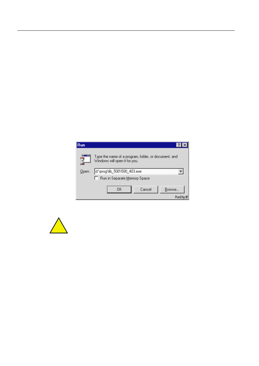
It is also possible to install LIB 500 from the RUN menu by typing the file name and
path:
)LJ
([DPSOHZKHQLQVWDOOLQJ/,%IURPWKH581PHQX
!
For latest information about name and path for actual release, please refer to the
release notes.
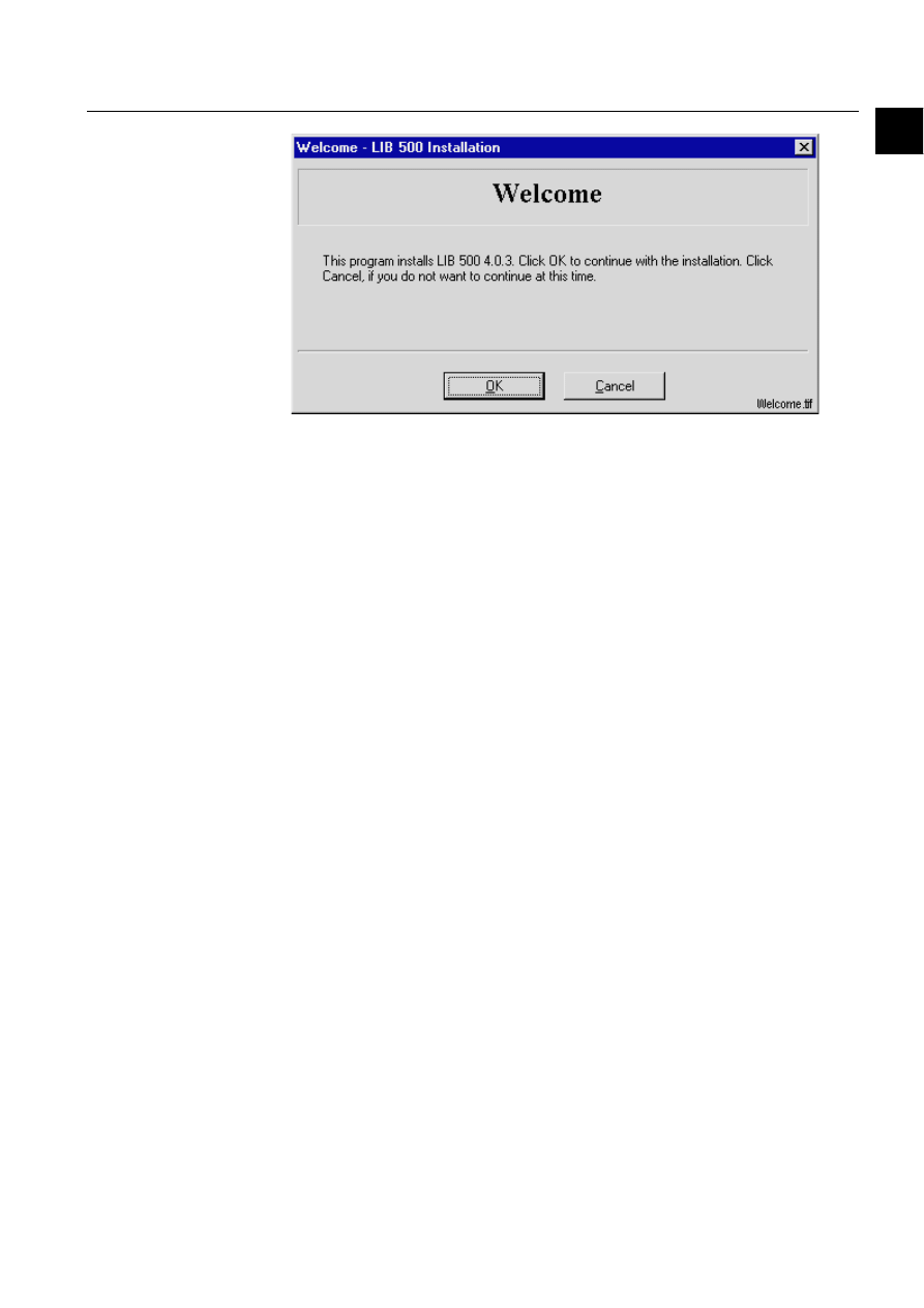
LIB 500 installation wizard
This Wizard will guide you through the installation of the LIB 500 4.0.3 Product
package. The installation is started when all selections are made and the ‘Start’
button is pressed in the LIB 500 Product installation dialog.
Welcome
A 'Welcome!' dialog is displayed with a short description of the product that you are
going to install.
1MRS751880-MEN
LIB 500
3
LIB 500 Configuration Manual
Configuration Guide
1. Installation of LIB 500
1
)LJ
7KH:HOFRPHGLDORJRIWKH/,%,QVWDOODWLRQ
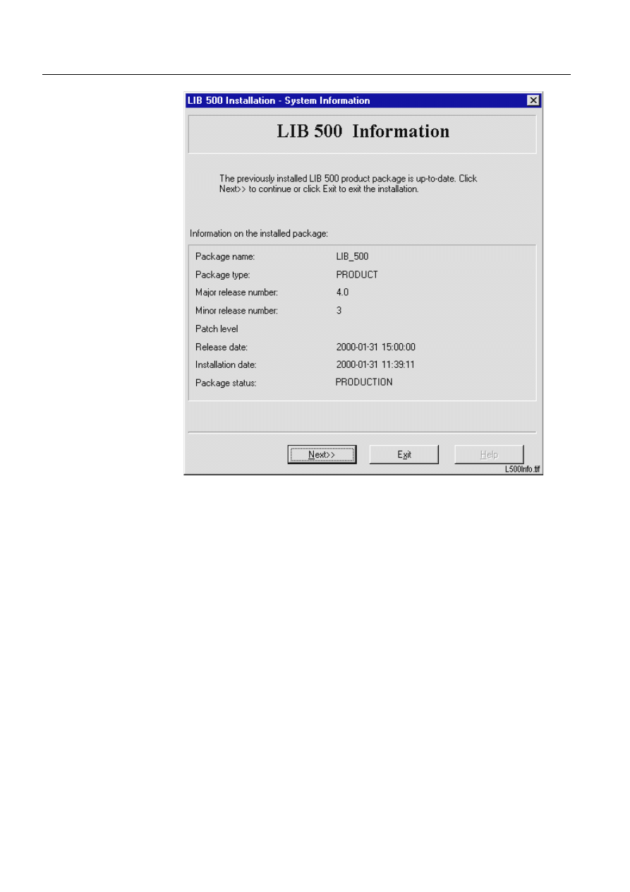
System information
If a previous version of LIB 500 has been installed on the computer, a dialog with
system information about the Installed version will be opened. It is now possible to
choose ’Next>>’ to continue the installation or ’Exit’ to stop the installation session.
4
1MRS751880-MEN
LIB 500 Configuration Manual
LIB 500
1. Installation of LIB 500
Configuration Guide
)LJ
/,%LQVWDOODWLRQV\VWHPLQIRUPDWLRQRQWKHSUHYLRXV
LQVWDOODWLRQ
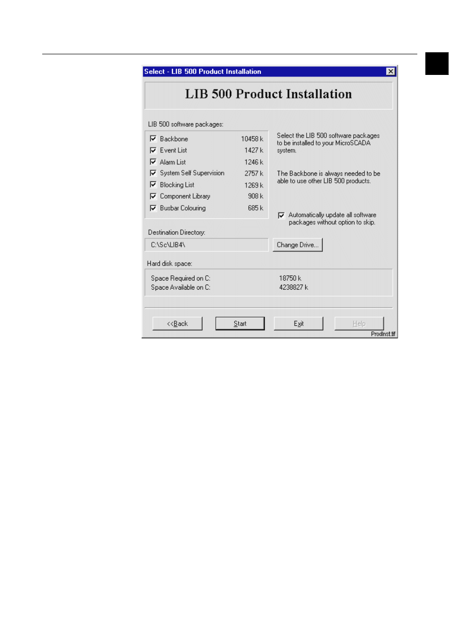
Select functions for installing
If you select the Next button, the main dialog of the installation routine, ’LIB 500
Product Installation’, is displayed (see Figure 1.2.2.-4). This dialog provides the
following information:
• All available LIB 500 software packages that can be installed
• Disk space required for each software package separately
• Disk space required for a total installation
• Disk space available on the selected destination drive
• The selected destination drive and a valid destination directory
• A general description of important information.
The selected software packages are installed to the selected destination directory
when 'Start' is selected. By selecting 'Exit', the 'Exit Dialog' is opened. From this
dialog it is still possible to return to the main installation dialog.
1MRS751880-MEN
LIB 500
5
LIB 500 Configuration Manual
Configuration Guide
1. Installation of LIB 500
1
)LJ
7KHVHOHFWLRQRI/,%VRIWZDUHSDFNDJHVIRULQVWDOODWLRQ
Start installation
The whole installation is started when the ‘Start' button is clicked. At this stage the
copying of selected functions to the destination will be started. The Installation will
also upgrade the 'Product Info' presented in the 'Application Setting' tool of LIB 500.
The product info can also be viewed from the LIB 500 4.0.3 Product Info tool in
backbone by typing <drive>/lib4/base/bbone/use/lib500r.exe. With this tool the
revisions of the installed LIB 500 software packages can be viewed or saved to a text
file.
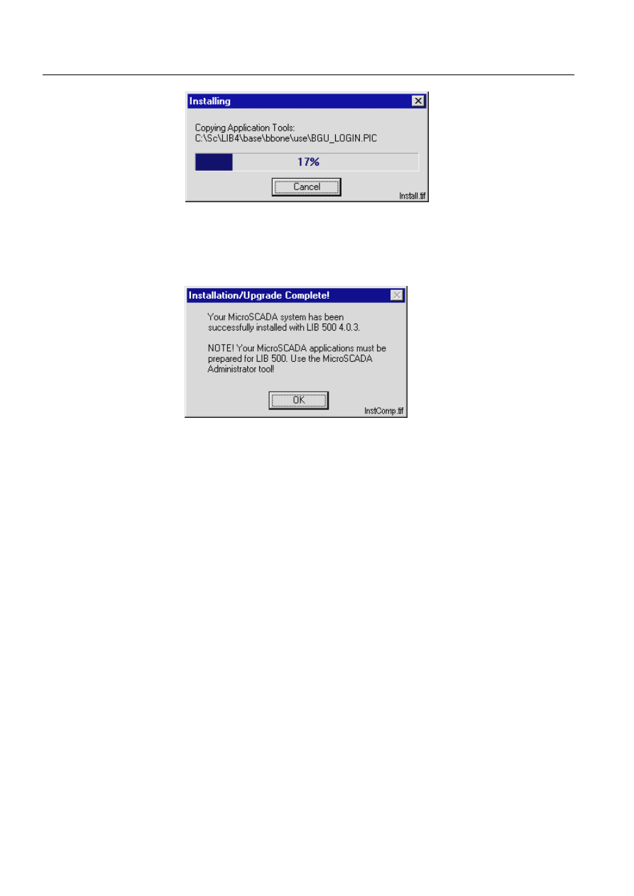
The progress bar dialog is showing the progress with a percentage value and a
graphic bar. A label text informing about what type of product and what files that
are copied is presented above the graphic bar. Pressing the 'Cancel' button will open
the 'Exit installation' dialog with the possibility to stop the copying before it is
finished. The files that already have been copied must in that case be deleted
manually.
6
1MRS751880-MEN
LIB 500 Configuration Manual
LIB 500
1. Installation of LIB 500
Configuration Guide
)LJ
7KH/,%LQVWDOODWLRQLVUXQQLQJ
Installation completed
A successful installation is ended with an information dialog.
)LJ
7KH/,%LQVWDOODWLRQLVFRPSOHWHG
The software packages are now installed in the following directories:
%DFNERQH
(drive) :/sc/lib4/base/bbone/inst
(drive) :/sc/lib4/base/bbone/lang0
(drive) :/sc/lib4/base/bbone/use
(YHQW/LVW
(drive) :/sc/lib4/base/event/inst
(drive) :/sc/lib4/base/event/lang0
(drive) :/sc/lib4/base/event/use
$ODUP/LVW
(drive) :/sc/lib4/base/alarm/inst
(drive) :/sc/lib4/base/alarm/lang0
(drive) :/sc/lib4/base/alarm/use
6\VWHP6HOI6XSHUYLVLRQ
(drive) :/sc/lib4/base/system/inst
(drive) :/sc/lib4/base/system/lang0
(drive) :/sc/lib4/base/system/use
1MRS751880-MEN
LIB 500
7
LIB 500 Configuration Manual
Configuration Guide
1. Installation of LIB 500
1
%ORFNLQJ/LVW
(drive) :/sc/lib4/base/block/inst
(drive) :/sc/lib4/base/block/lang0
(drive) :/sc/lib4/base/block/use
%XVEDU&RORXULQJ
(drive) :/sc/lib4/base/bbcol/inst
(drive) :/sc/lib4/base/bbcol/lang0
(drive) :/sc/lib4/base/bbcol/use
&RPSRQHQW/LEUDU\
(drive) :/sc/lib4/base/slib/inst
(drive) :/sc/lib4/base/slib/lang0
(drive) :/sc/lib4/base/slib/use
After a full installation of LIB 500, the structure is as described in the following
section.
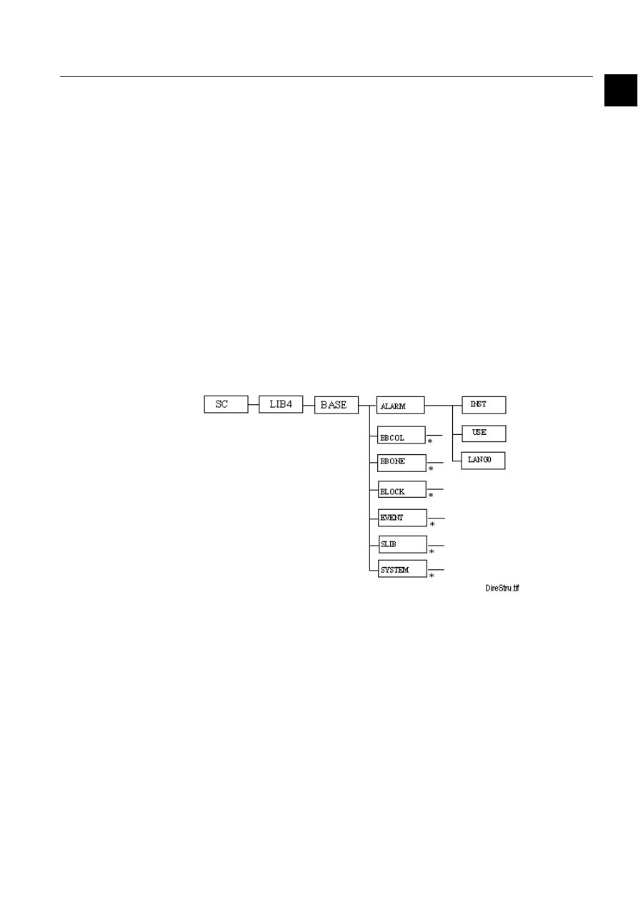
1.3.
Location of the LIB 500 software packages
The LIB 500 software packages are stored on the hard disk in the following way:
)LJ 7KH/,%GLUHFWRU\VWUXFWXUH
*) The standard directory structure (inst, use, lang0) is available for all functions in
BASE.


1MRS751880-MEN
LIB 500
9
LIB 500 Configuration Manual
Configuration Guide
2. Introduction
2
2. Introduction
2.1.
General
2.1.1.
Preface
Welcome to the LIB 500 Introduction Configuration Manual. This document will
provide you with information for installing, configuring, modifying and using the
different parts of the LIB 500 product package.
Previous experience of MicroSCADA and LIB 5xx is an advantage when studying
this document.
2.1.2.
References
The following documents are related to this document and the operation of the LIB
500 functions.
Table 2.1.2-1
The documents related to this document and the operation of
the LIB 500 functions
2.1.3.
Abbreviations and Definitions
Table 2.1.3-1
Abbreviations and Definitions
Document
Identification
Introduction to MicroSCADA Technology
1MRS751852-MUM
Programming Language SCIL
1MRS751849-MEN
MicroSCADA Application Objects
1MRS751848-MEN
Base picture
Background picture (the base on which standard functions are
installed)
BBONE
Backbone
CMOD
CHPAU modules
DMOD
DEUTA modules
FMOD
FISUB modules
HDB
History Database
HV
High voltage
LAN
Local Area Network
LEC
Local engineering center
LIB 500
Application Library 500, the common platform (Base) for ABB
application engineering within MicroSCADA
LIB 510
Product including FISUB functions
LIB 520
Product including SEAPR functions
LIB 530
Product including CHPAU functions
LON
Local Operating Network
MicroLIBRARY
Application Library, previous to LIB 500
MV
Medium voltage
1MRS751880-MEN

10
1MRS751880-MEN
LIB 500 Configuration Manual
LIB 500
2. Introduction
Configuration Guide
2.1.4.
Font conventions
Normal text is written in this font and size.
SCIL CODE, SCIL PROGRAMS AND FILE NAMES ARE WRITTEN WITH THIS FONT AND SIZE.
2.2.
Fundamental concepts
2.2.1.
Application engineering
The application engineering is performed by composing LIB 500 standard functions
(described below) to pictures. The objects connected to various functions are created
automatically as the standard functions are included in the pictures.
Standard picture functions in the LIB 500 are installed to the application picture by
the means of Installation Tool in the Picture Editor. After that the picture function is
configured by the means of the Standard Configuration Tool. The picture is stored
in the Pict directory. The picture function is also dependent on the picture belonging
to the following objects:
• Process objects
• Scales
• Data objects
• Command Procedures
• Event Channels
• Time Channels
For more information, please refer to Section 2.3.1.
2.2.2.
Application framework
The LIB 500 application framework constitutes a functional application base of
standard design. The framework consists of:
• A configurable menu bar with a predefined default menu.
PC
Production center
Process symbol
Graphical presentation of a standard function in run-time
RMU
Ring Main Unit
SCT
Standard Configuration Tool
SG
LIB 500 Style Guide
IT
Installation Tool
SLIB
Component library for development of application specific functions
SMOD
SEAPR modules
SDD
System Design Description
SCS
Substation Control System (a system for monitoring and controlling a
complete substation); in this document MicroSCADA
TCP/IP
Transmission Control Protocol/Internet Protocol
XMOD
Other LEC specific modules, new modified modules
Base picture
Background picture (the base on which standard functions are
installed)

1MRS751880-MEN
LIB 500
11
LIB 500 Configuration Manual
Configuration Guide
2. Introduction
2
• A user authorization mechanism
• A number of special pictures for password handling, application settings etc.
The application framework is described in chapter 3.
2.2.3.
Standard functions
The standard functions of LIB 500 are standard elements used for designing
different types of application pictures. A standard function is an ordinary picture
created by means of the Picture Editor. It may contain almost all picture elements,
such as background, start, update and exit programs, function keys and windows.
The only technical restriction is that it may not contain picture functions. There are
no restrictions on the size of the background.
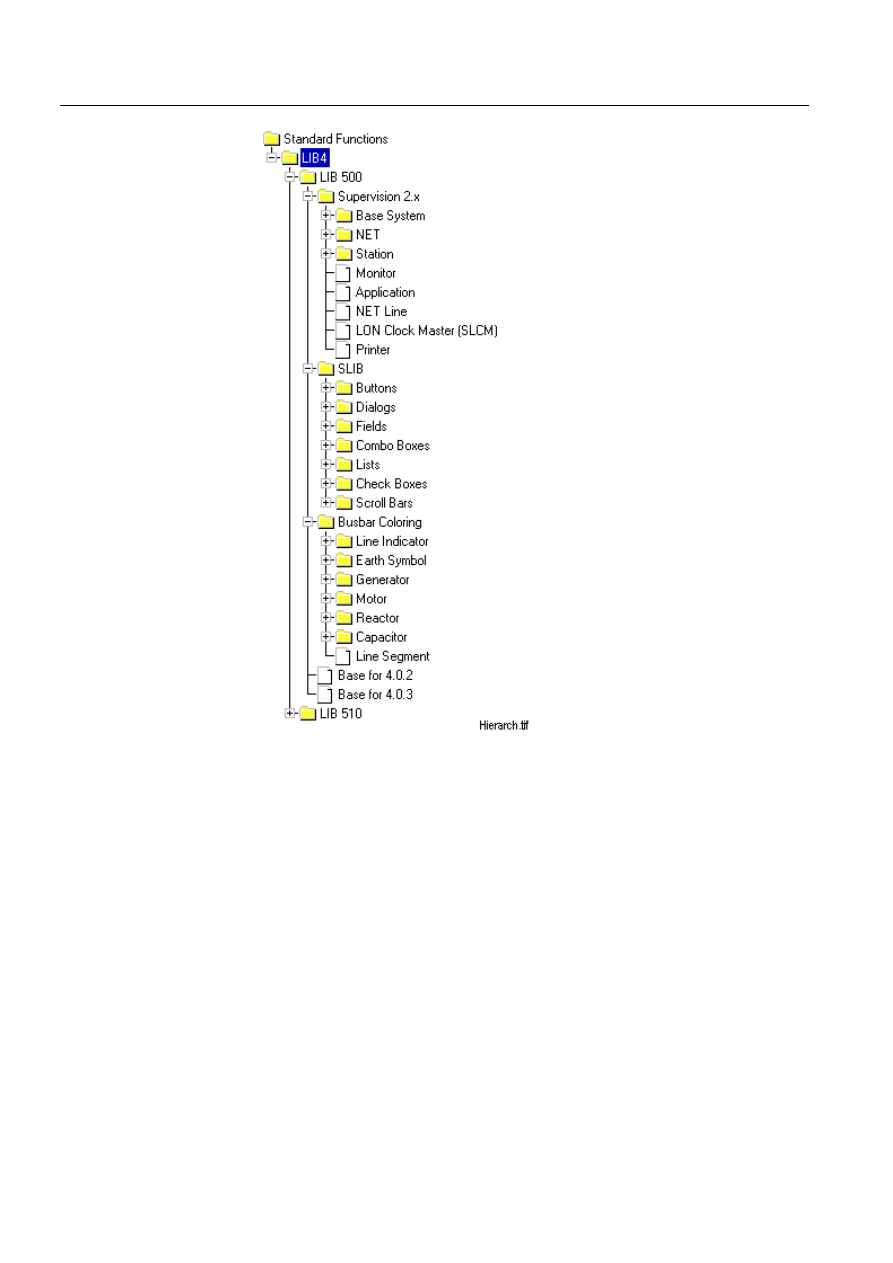
In LIB 500, the standard functions are grouped and organized in a menu structure
according to their purposes (see (see Fig. 2.2.4.-1)).
2.2.4.
Picture functions
The picture functions are functional elements that the application pictures are
composed of (also other picture elements may be included). When a LIB 500
standard function is installed into an application picture, it becomes a picture
function.
A picture function is a part of the application picture although it has picture elements
of its own, such as picture background, start, update and exit programs, function
keys and windows. Each picture function is equipped with a name that must be
unique within the picture. A picture function may be repositioned. All elements of a
picture function can be viewed.
12
1MRS751880-MEN
LIB 500 Configuration Manual
LIB 500
2. Introduction
Configuration Guide
)LJ
7KH/,%VWDQGDUGIXQFWLRQPHQXKLHUDUFK\
When a picture is produced on screen, e.g. with the !NEW_PIC command, the start
program of the main picture is executed first, and then the start programs of the
picture functions are run in the order of installation.
2.2.5.
Installation and configuration tools
The installation of standard functions is divided into two main parts:
1. Installation
2. Configuration
During the installation, the user is asked to give a name (the length of which may be
from 1 to 10 characters) for the picture function and to define the position of the
picture function in the base picture. These can be chosen freely.
During the configuration, the default settings may be changed. Process objects are
created with the Process Object Tool. An advantage of this procedure is that several
picture functions can be installed at once without leaving the Installation Tool, and
1MRS751880-MEN
LIB 500
13
LIB 500 Configuration Manual
Configuration Guide
2. Introduction
2
that the Standard Configuration Tool can be brought up afterwards for the
adjustment of configurable parameters and the creation of the process objects.
2.3.
LIB 500 engineering Principles
When using LIB 500, the application pictures are built in the standard MicroSCADA
Picture Editor (MicroSCADA Tool Manager). By means of the Picture Editor the
standard functions are included, "installed", one by one into the picture. When all
desired picture functions have been installed and configured, the picture is ready for
use. Installed picture functions can be moved and deleted, and in certain cases
copied.
2.3.1.
Picture function handling
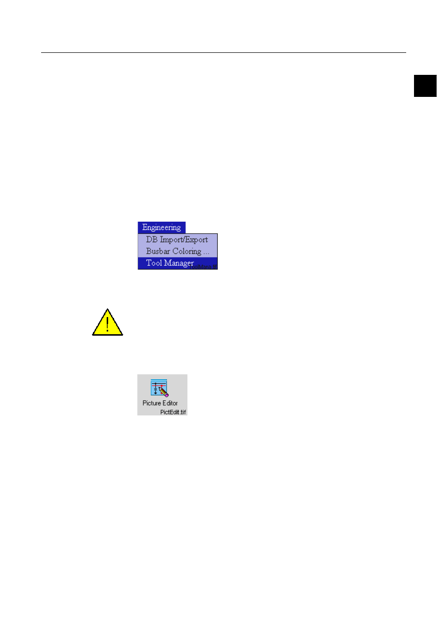
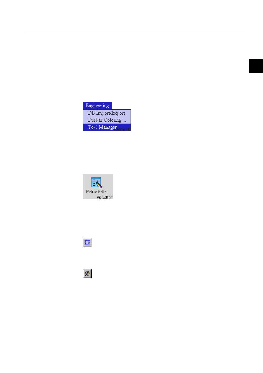
2.3.1.1.
Starting
In the Engineering menu, select the Tool Manager menu.
)LJ 6HOHFWLQJWKH0LFUR6&$'$7RRO0DQDJHUIURPWKH(QJLQHHULQJ
PHQX
To be able to access the Tool Manager, the user needs to have authority level 2 or
higher for authority group Tools.
Start the Picture Editor in the User Interface folder by double clicking the icon.
)LJ 'RXEOHFOLFNWKH3LFWXUH(GLWRULFRQWRVWDUWLW
The following step is to open an existing picture or to start with a blank picture by
selecting File and Open or by selecting a picture from the list in the File menu.
2.3.1.2.
Installation of picture functions
The procedure when installing standard functions from LIB 500 into an application
picture is roughly described to be handled as follows:
14
1MRS751880-MEN
LIB 500 Configuration Manual
LIB 500
2. Introduction
Configuration Guide
Choose
3LFWXUH)XQFWLRQVin the(GLWmenu or use the dedicated button:
To install a picture function:
Click the button to open the Installation Tool
The Installation Tool can also be started with
6KRZ/LEUDU\in the/LEUDU\menu
or by pressing <Ctrl> and L at the same time.
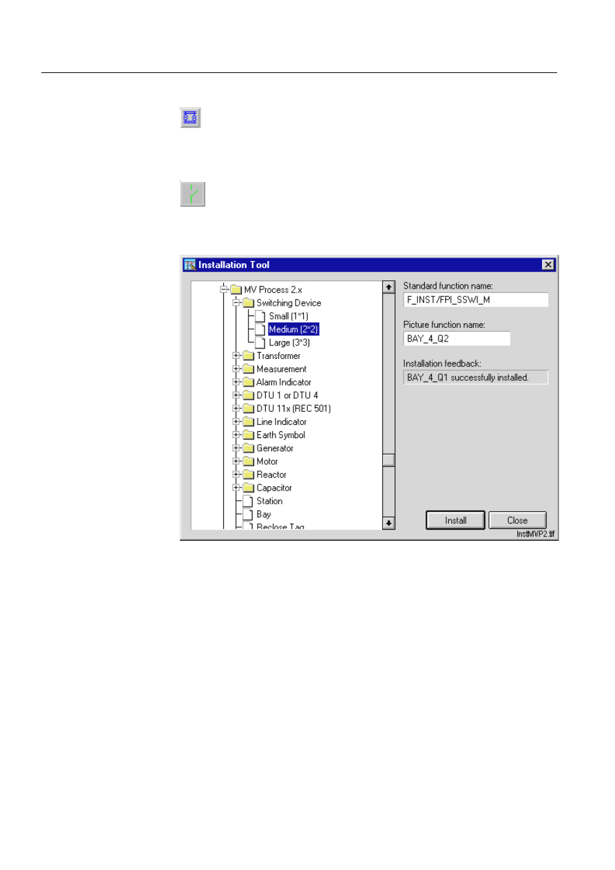
)LJ ,QWKLVGLDORJ\RXFDQFKRRVHIURPWKHOLEUDU\WKHSLFWXUHIXQFWLRQ
\RXZDQWWRLQVHUWLQWRWKHSLFWXUH
• The available picture functions are shown in the Installation Tool. The main list
contains several sublists. Click the plus mark to expand one level. Click the name
of the standard function you want to install and select size.
• Type the name you want to use to identify the function in the picture in the box
for Picture Function Name: Click INSTALL to install it to the picture and the
installed picture function appears on the screen.
• After one picture function has been installed, the tool suggests a name for the
next one. To install several picture functions of the same type, just click Install
several times. The installed picture functions are given the suggested names,
unless another name is given.
You can also install standard functions that are not shown in the tree by typing their
name including the path. The name is typed in the Picture Function Name box.
1MRS751880-MEN
LIB 500
15
LIB 500 Configuration Manual
Configuration Guide
2. Introduction
2
Exit the Installation Tool by clicking Close.
2.3.1.3.
Selecting a picture function
To select a picture function for editing:
Click the selector button
Click the border of the element you want to select. When an element is selected it is
surrounded by control pointers or so called handles.
When a picture function is selected, it can be moved, deleted or zoomed.
2.3.1.4.
Configuration of picture functions
Picture functions have a set of configurable attributes, which can be changed
afterwards. The configurations are stored in a list located in the DRAW-program of
the picture function. When you select the function in the Picture Editor, the Standard
Configuration Tool reads the name of the data file of the picture function. The data
file gives all needed data for doing the configurations by the Standard Configuration
Tool. The data file is used for giving the input what the configuration tool asks for
and how it operates. It contains lists of configurable attributes, standard function
specific tools, user programs, standard configuration tool menu definitions, process
object definitions and programs to be executed when delete, cancel or OK is chosen.
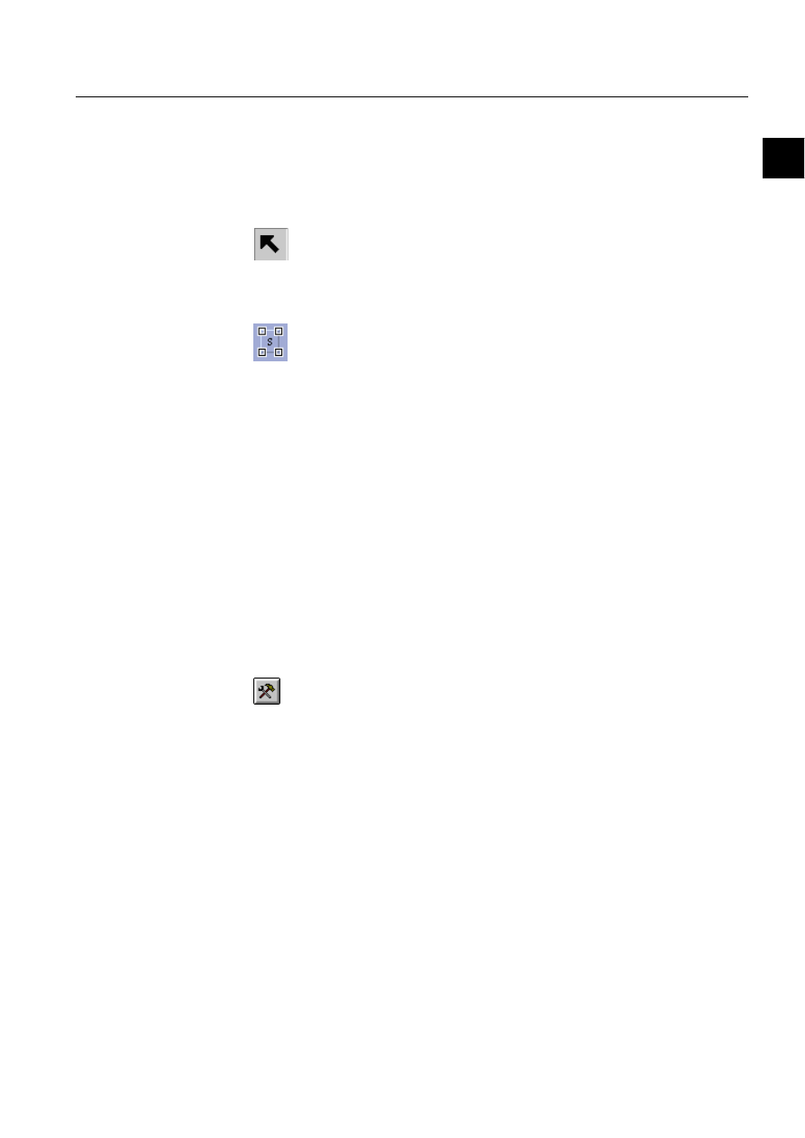
To configure a picture function:
• Select the picture function, see previous section
• Click the configure button
• or select Configure Function in the Library menu
• In the Standard Configuration Tool you can configure attributes, edit programs or
use other standard function specific tools
Standard Configuration Tool
Attribute folder
The first folder, the Attribute folder, of the Standard Configuration Tool contains the
attributes to be configured for the selected picture function. Type the configuration
information in the text boxes or choose one of the listed options.
16
1MRS751880-MEN
LIB 500 Configuration Manual
LIB 500
2. Introduction
Configuration Guide
)LJ 7KH$WWULEXWHIROGHULQWKH6WDQGDUG&RQILJXUDWLRQ7RRO
Tip: The Copy attributes and Paste attributes functions can be used for copying
common attribute settings for elements used within the same Station or Bay.
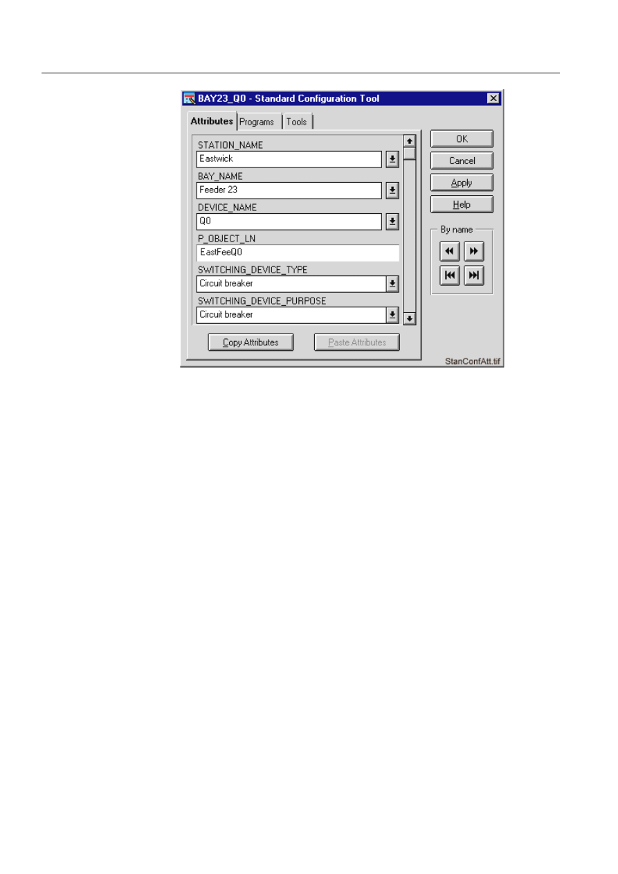
Programs folder
The second folder, the Programs folder, enables editing of a named program. Select
the program and click Edit.
1MRS751880-MEN
LIB 500
17
LIB 500 Configuration Manual
Configuration Guide
2. Introduction
2
)LJ 7KH3URJUDPVIROGHULQWKH6WDQGDUG&RQILJXUDWLRQ7RRO
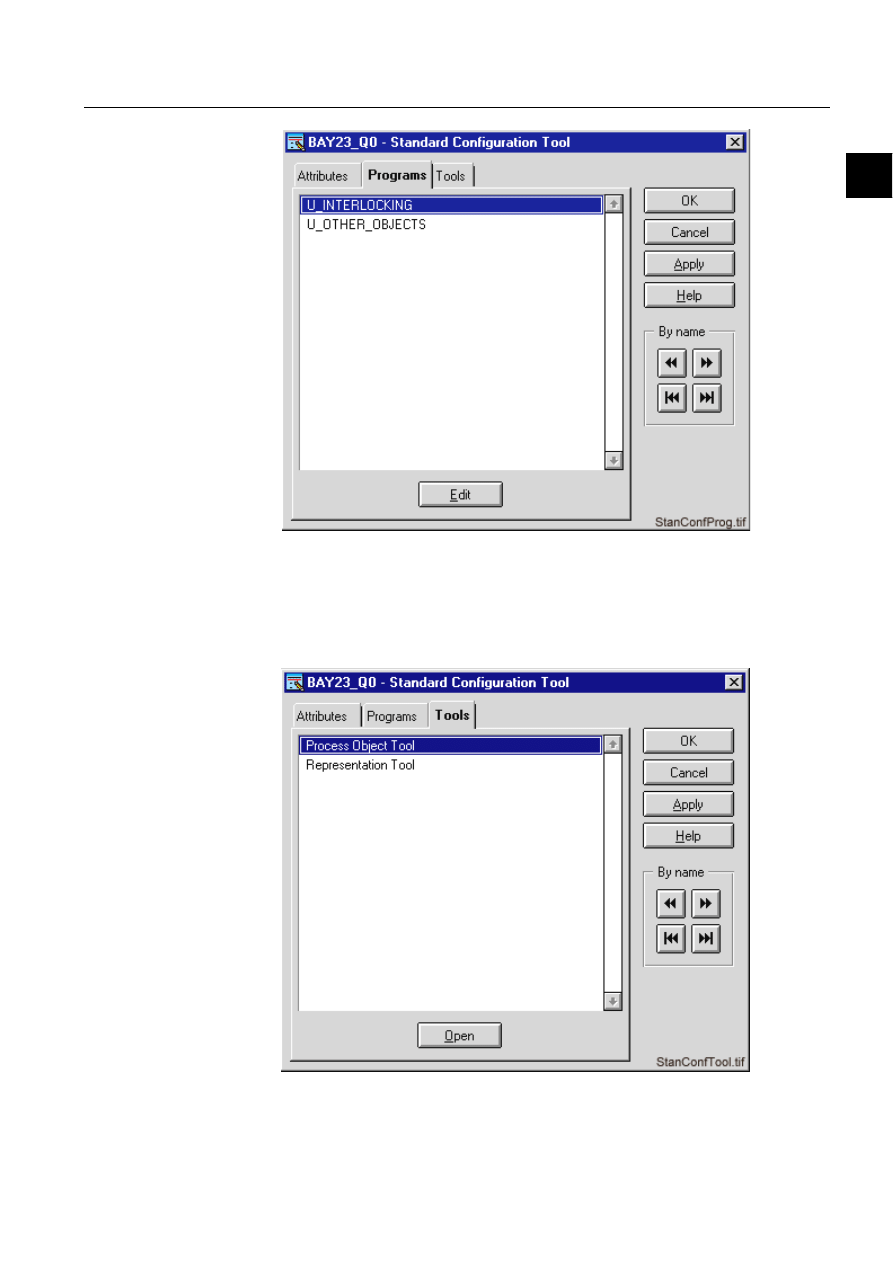
Tools folder
The third folder, the Tools folder, contains picture function specific tools. Select the
desired tool and click Open.
)LJ 7KH7RROVIROGHULQWKH6WDQGDUG&RQILJXUDWLRQ7RRO
18
1MRS751880-MEN
LIB 500 Configuration Manual
LIB 500
2. Introduction
Configuration Guide
To exit the Standard Configuration Tool:
• Click Apply to confirm the changes you have made or OK to confirm the changes
and exit the Standard Configuration Tool. To exit the tool without confirming and
saving the changes, click Cancel.
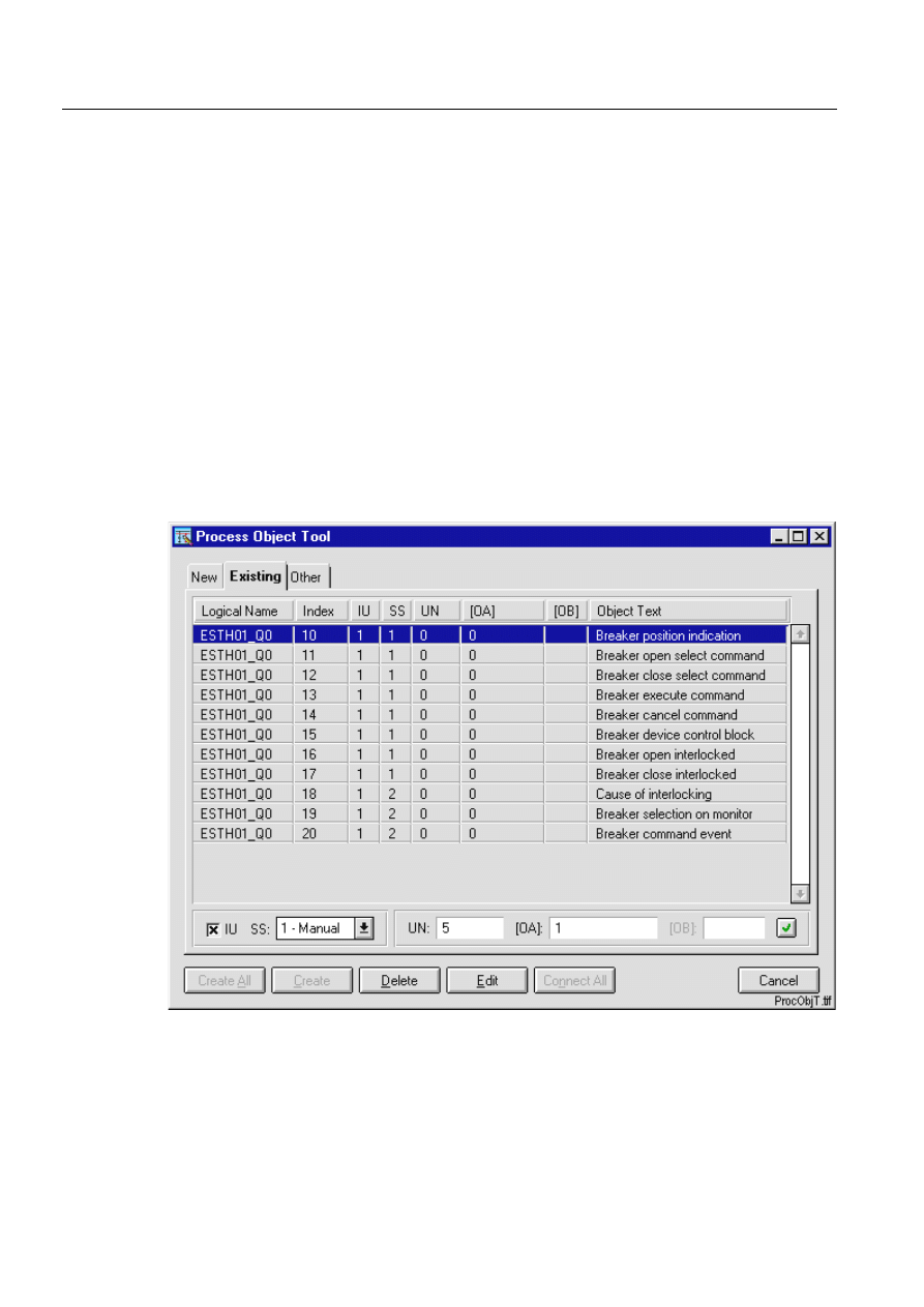
3URFHVV2EMHFW7RRO
Configuring picture functions
• The Process Object Tool consists of three folders including process objects with
different status New, Existing and Other.
• For a currently installed picture function all process objects will have the status
new. Create all will create the database object for all process objects that belong
to the picture function. All process objects created can be viewed from the
Existing folder.
• A selective Create, Delete or Edit of a process object can be done by selecting the
object and then clicking the push-button of the function. Multiple selection can be
done for Create and Delete.
• The Edit function opens the standard Process Object Edit Tool.
)LJ 7KH3URFHVV2EMHFW7RROZLWKH[LVWLQJSURFHVVREMHFWV
• Exit the Process Object Tool with Cancel.
1MRS751880-MEN
LIB 500
19
LIB 500 Configuration Manual
Configuration Guide
2. Introduction
2
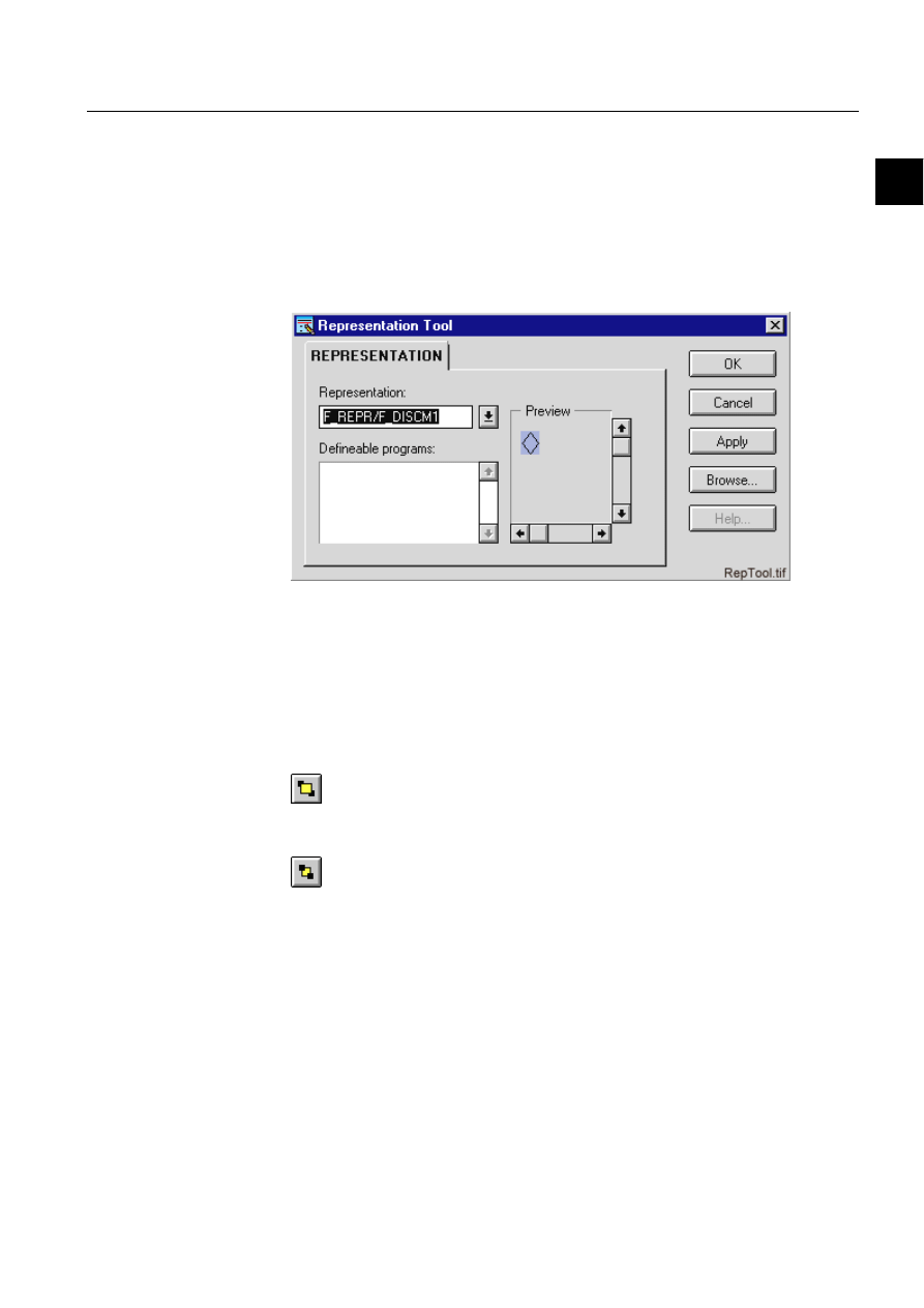
Representation Tool
Configuring representations
• Click the Representation drop-down list to change to another symbol for the
object. The symbols are previewed as you scroll through the available
representations in the list with the scroll arrows up and down.
• Another representations available can easily be selected using the Browse
function. When the selection is done, it is confirmed with Apply or OK.
)LJ 7KH5HSUHVHQWDWLRQ7RRO
2.3.1.5.
Layer arrange of picture functions
In the full graphic Picture Editor you can freely choose the execution order of picture
functions and the main picture graphics.
The order of the graphic layers can be changed with the help of function called
Drawing Order or by selecting raising
or lowering functions.
The order of graphic layers can be changed either by the function
'UDZLQJ2UGHU
in the menu
9LHZPHQXor by the $UUDQJH raising and lowering functions %ULQJWR
)URQW, 6HQGWR%DFN, %ULQJ)RUZDUG and 6HQG%DFNZDUG.
When using the raising and lowering functions, each new element, which is added
to the picture background, is placed on top of the previous ones. When elements
have the same location or they overlap, the new element will cover the one drawn
previously.
The raising and lowering functions can be mixed in several ways to produce the
correct order of the elements. You can raise and lower background elements and
picture functions, but not windows or keys.

20
1MRS751880-MEN
LIB 500 Configuration Manual
LIB 500
2. Introduction
Configuration Guide
2.3.1.6.
Moving picture functions
The picture functions installed in a picture can be repositioned any time without
changing their functions:
To move an element:
• Select the element. A selected element can be recognised by the control points
• Press down the
OHIWPRXVHEXWWRQ on top of the element and hold it down while
dragging the pointer to the
QHZSRVLWLRQ.
A selected element can also be moved by the arrow buttons in the keyboard at a rate
of one grid point for each time an arrow button is pressed. In the background mode
the elements move one SCIL unit when the cursor key is pressed (without Shift). In
window, function and key modes the elements always move one grid point which is
equal to 16 horizontal and 20 vertical SCIL units. This particular size of the grid unit
belongs to a system of 48 lines with 80 character positions each. Please note that
usually the SCIL unit is not equal to a pixel.
To move an element (except for a picture function) from one picture to another:
• Select
the element.
• Choose
&XW in the (GLWPHQX.
•
2SHQ the picture where you want to place the element. If you have not saved
changes to the old picture, you can also do it at this point. Click
3DVWH.
• The
QHZHOHPHQW, which was moved from another picture, appears in the upper
left corner of the drawing area.
• Hold the left mouse button down while pointing on the new element and move it
with the pointer
to the new location.
2.3.1.7.
Deleting picture functions
Picture functions without any connections to databases can be deleted directly in the
Picture Editor.
To delete a picture function element:
• Select the element with the
VHOHFWRU
•
Then click at WKHERUGHURIWKHHOHPHQW
• Choose
'HOHWH in the (GLWPHQX and the element disappears. This can also be
done by pressing Delete on the keyboard.
However, often various types of database objects (object functions) are created as a
picture function is installed. If the picture function is deleted, these database objects
should be deleted as well. The object deletion must be performed by a special tool
picture with knowledge about the object functions. Normally, this picture is the
Process Object Tool. In any case, the
'HOHWH function can be used. Another picture
is automatically brought up if the picture function cannot be deleted directly.
The deletion of standard functions of different types is described in detail in the
sections where the respective types are considered.

1MRS751880-MEN
LIB 500
21
LIB 500 Configuration Manual
Configuration Guide
2. Introduction
2
2.3.1.8.
Deleting application pictures
When an application picture containing picture functions is deleted, the picture
functions are deleted, too. However, the object related to the picture functions are
not deleted. Therefore, the picture functions connected to database objects should be
deleted individually before the pictures are deleted.
2.4.
Files and directories
2.4.1.
Directory structure
The following convention is used in the directory naming:
n = 0,1, ...
corresponds to different language versions. The number is monitor
specific and defined from LIB 500 ‘User management/Application
Settings’.
Common structure for each standard function/tool:
Table 2.4.1-1
The LIB 500 package includes the following directories
Table 2.4.1-2
LIB 500 structure
Table 2.4.1-3
The LIB 5xx packages include the following additional
directory structure
LIB4/BASE/xxxx/
INST
Installation/configuration files
USE
Runtime files
LANGn
Language dependent files, e.g. help files
LIB4/BASE/
BBONE
Application Framework files, menus
EVENT
Event list
ALARM
Alarm list
SYSTEM
System self supervision
BLOCK
Blocking List
BBCOL
Busbar Colouring
SLIB
Component Library
LIB4/
FMOD
FISUB modules; e.g. MVPROCESS
SMOD
SEAPR modules
CMOD
CHPAU modules
DMOD
DEUTA modules
xMOD
Modules made by LEC
RMOD
REC 580 modules (SEAPR)

22
1MRS751880-MEN
LIB 500 Configuration Manual
LIB 500
2. Introduction
Configuration Guide
Table 2.4.1-4
An LIB 500 application includes the following directories
*) Uses the standard structure with INST, USE, LANGn
**) MicroLIBRARY 3.1 (or previous)
2.4.2.
Modifying LIB 500 functions
The following conventions should be followed when LIB 5xx functions are
modified and when the modifications should not be overwritten at LIB 5xx updating.
The function that is to be modified must first be copied to the application directory
from the LIB4 function directory:
E.g. modification of LIB 510 MV Process:
Table 2.4.2-1
Copy files to modify from
Table 2.4.2-2
Copy to
2.4.3.
Making LIB 500 functions
The following conventions should be followed when LIB 5xx functions are made.
The structure of the own functions should follow the LIB 5xx standard structure,
(more details can be found in the document System Design Description; SDD).
Table 2.4.3-1
Example of structure
APL/xxxx/
APL_
Databases, library representations, start picture,
etc.
PICT
Application pictures
FORM
Format pictures
PAR
MicroSCADA base tools
APLMOD4
Modified LIB 500 files *)
MLIB_FG
Modified MicroLIBRARY 3.1 (or previous) files
**)
HELPn
Application specific help files **)
TEXTS_FGn
Application specific text files **)
LIB4/FMOD/MVPROCESS/
INST
USE
LANGn
APL_/xxxx/APLMOD4/
INST
USE
LANGn
LIB4/xMOD/
INST
Installation/configuration files
USE
Runtime files
LANGn
language dependent files, e.g. Help files

1MRS751880-MEN
LIB 500
23
LIB 500 Configuration Manual
Configuration Guide
2. Introduction
2
x = Character recorded by FISUB; e.g. B = BASE, F = FISUB, S = SEAPR, C =
CHPAU
2.5.
Languages in LIB 5xx
2.5.1.
Scope of support
• Each application can support, practically, up to 99 language versions.
• The language is monitor specific.
• Database texts and event printouts do not support language switching.
• The language dependent texts are stored in text files.
LIB 5xx supports the use of multiple languages in pictures and printouts. Different
users can have texts in different languages in the same application. All language-
dependent texts are read from text files stored on the hard disk. The default language
in LIB 500 is English, the use of multiple local languages is supported. A “Text
Translation Tool” tool for translating LIB 5xx text files is available in
MicroSCADA Base Tools. Menu text files (see SG for details) are translated with
the Menu Configuration Tool.
2.5.2.
Language settings in LIB 5xx
LIB 500 provides three language settings. The output of each language setting is the
number corresponding to the number of the LANG* directory when defining the
language-dependent logical paths (see SDD for details). The following language
settings are provided:
• User language defined in the user management picture for each user. This setting
determines the language of the texts shown on the screen.
• Monitor language defined in the application settings picture. With this setting the
language of texts shown on the screen can be temporarily changed. When the
monitor is closed, this setting is reset. User language is the default value of
monitor language.
• Application language defined in the application settings picture. This setting
determines the language of the printouts and the language used in the command
procedure queue.

1MRS751880-MEN
LIB 500
25
LIB 500 Configuration Manual
Configuration Guide
3. Backbone
3
3. Backbone
3.1.
Standard function base
3.1.1.
Overview
Information concerning operation is also provided in the LIB 500 Operator’s
Manual, Chapter 2 Backbone.
)LJ
6WDQGDUG%DVH
• File name:
BGI_BASE.PIC
• File location in package:BBONE/INST
3.1.1.1.
Description
The base function is used as the base in all LIB 500 application pictures regarding:
• Menu configuration
• Default links to LIB 500 base functionality via the default menu items
1MRS751880-MEN

26
1MRS751880-MEN
LIB 500 Configuration Manual
LIB 500
3. Backbone
Configuration Guide
3.1.1.2.
Target systems
• Not target dependent
3.1.1.3.
Communication support
There are no communication dependencies in the Base standard function.
3.1.1.4.
Features/options
• Title bar
• Date and Time presentation
• Toolbar short-cuts to Event and Alarm List, Hard Copy, Audio Alarm
Acknowledgement
• Alarm indication
• Alarm row drop-down for alarm acknowledgement
• Authorization support
• Help
3.1.1.5.
Process commands
No process commands are possible for the Base.
3.1.2.
Installing and configuring
Table 3.1.2-1
Installing and configuring
The installation of application specific picture functions is described in Chapter 7.
Configurable attributes
Choices
PICTURE_HEADER
(Type text). The title of the picture. The title is shown
on the picture header bar.
SHOW_ALARMROW
The alarm row can be set not in use (Never), to be
shown only when there are unacknowledged alarms
(When alarms), or to be shown always (Always).
STANDARD_MENU_PART
States where the standard menu part is fetched. It can
be a text file or a named program. Syntax: ’logical
path’/’file name’ or .my_named_program. Examples:
B_LANG/STAN_MN.TXT
.DEFINE_ST_MENU_BAR
SPECIFIC_MENU_PART
States from where the picture specific menu part is
fetched. It can be a text file or a named program.
Syntax: ’logical path’/’file name’ or
.my_named_program. Examples:
B_LANG/SPEC_MN.TXT
.DEFINE_SP_MENU_BAR
HELP_MENU_PART
States from where the help menu part is fetched. It can
be a text file or a named program. Syntax: ’logical
path’/’file name’ or .my_named_program. Examples:
B_LANG/HELP_MN.TXT
.DEFINE_HL_MENU_BAR
1MRS751880-MEN
LIB 500
27
LIB 500 Configuration Manual
Configuration Guide
3. Backbone
3
3.1.3.
Configuring menus
The menus are configurable throughout the base function, and they are configurable
in three parts. By default, the Standard Part and the Help Part are common for all
pictures within an application. The Picture Specific Part holds items used in that
picture only. The sources where the menu definitions are fetched from are
configured in the base picture function of each picture.
3.1.3.1.
Starting the menu configuration tool
1. Open the Picture Editor by opening the Engineering menu and by selecting the
Tool Manager.
)LJ 6HOHFWLQJWKH0LFUR6&$'$7RRO0DQDJHUIURPWKH(QJLQHHULQJ
PHQX
127( To be able to access the Tool Manager, the user needs to have the authority
level 2 or higher for the authority group Tools.
Start the Picture Editor in the User Interface folder by double-clicking the icon.
)LJ 'RXEOHFOLFNWKH3LFWXUH(GLWRULFRQWRVWDUWLW
2. Open the base picture by selecting it in the File menu either by clicking first
Open and then By File Chooser or By Name. Another possibility is to select the
name of the picture on the list in the File menu.
3. Click the Picture Functions button
4. Select the picture by clicking it with the mouse so that handles appear in the
corners of the picture.
5. Click the Configure Function button
6. After clicking the above mentioned button, the Standard Configuration Tool
dialog box appears.
28
1MRS751880-MEN
LIB 500 Configuration Manual
LIB 500
3. Backbone
Configuration Guide
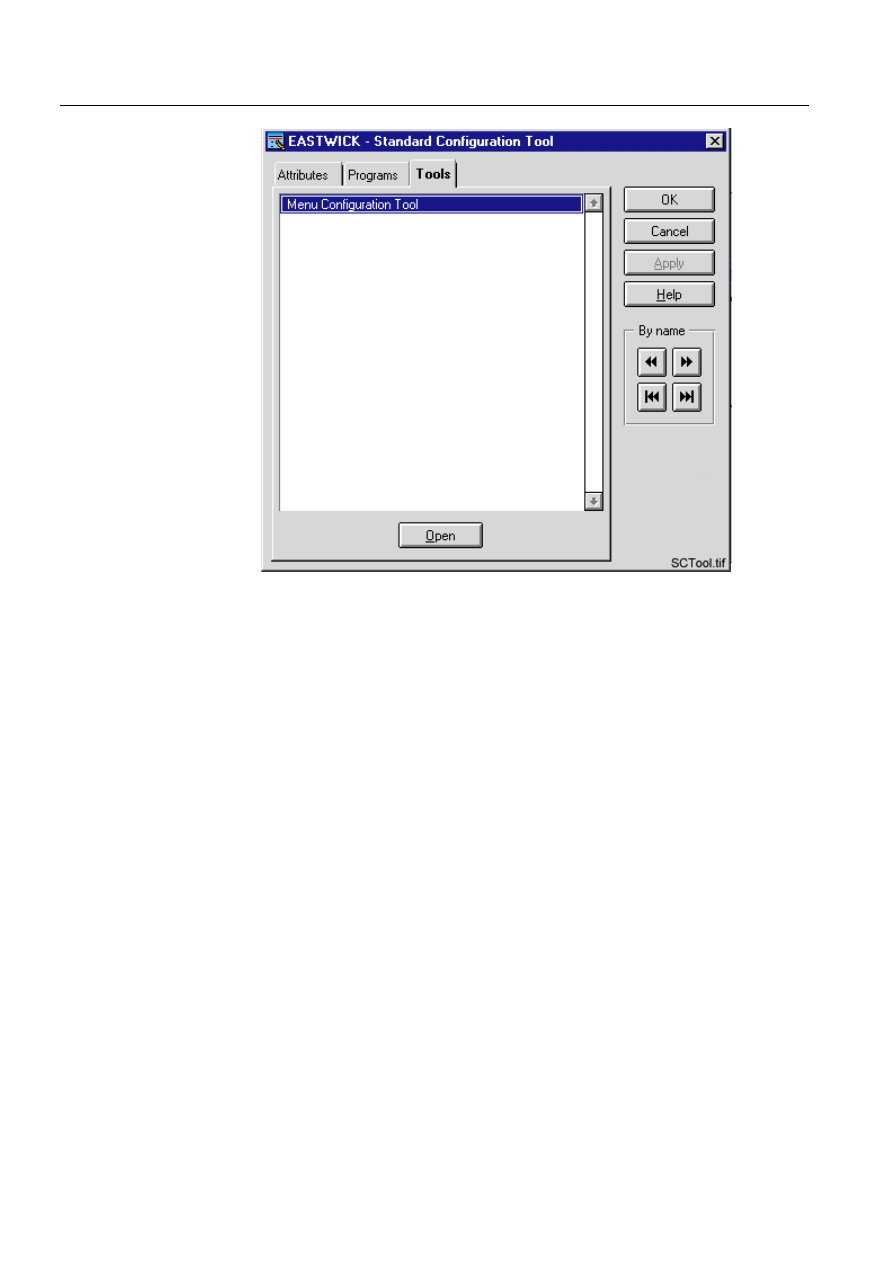
)LJ 6WDQGDUG&RQILJXUDWLRQ7RRO
Select the Tools tab by clicking the tab, select the Menu Configuration tool on the
list, and click the Open button under the list. The Menu Configuration Tool dialog
box appears.
1MRS751880-MEN
LIB 500
29
LIB 500 Configuration Manual
Configuration Guide
3. Backbone
3
3.1.3.2.
Functionality of the menu configuration tool main dialog
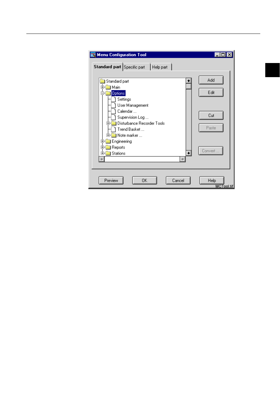
)LJ 0HQX&RQILJXUDWLRQ7RRO
The menu parts are shown as three pages in a notebook. The cascade items are
presented as folders and the normal items and separators are presented as menu
items. First the menu bar main items are shown. The contents of the main items can
be browsed through just by expanding the folders. The configurations are saved
under the application with OK and discarded with Cancel.
The menu items can be added by selecting an existing item (or the root folder, if no
items exist) and then selecting the Add button. A dialog is opened in which needed
definitions can be made. If the selected item is an expanded folder, the new item is
placed under the selected folder. If the selected item is a collapsed folder, the new
item belongs to the parent folder of the selected folder and is placed below the
selected folder. The main menu items (under root folder) can only be of cascade
type.
3.1.3.3.
Restoring the default menus
Sometimes it may be necessary to remove the changes made to the menus. For
instance to get new features when updating the LIB, or when a mistake has been
done and the user want to reset the changes.
To reset the picture header menus, you have to manually remove or rename certain
files. For backward compatibility reasons, the menu standards are saved in two
different ways. By default, with the base for LIB 500 4.02, the menu standard and
help part definitions are saved to the files /apl/’application’/apl_mod4/
lang’language’/bgu_h1stmn.txt and bgu_h1hlmn.txt. The menu standard and help
30
1MRS751880-MEN
LIB 500 Configuration Manual
LIB 500
3. Backbone
Configuration Guide
part action programs are saved under to the files /apl/’application’/apl_mod4/use/
bgu_h1stac.txt and bgu_h1hlac.txt. To restore the menus to the default view, delete
or rename these four files.
With base for 4.03 and newer, the definitions part and action part are saved into the
files /apl/’application’/apl_mod4/use/bgu_h2stand.mnu and bgu_h2help.mnu. In
this case there are only two files to delete or rename.
When these files are deleted or renamed, the application automatically uses the
default configuration files that also where in use before any changes where made to
the menus.
3.1.3.4.
Functionality of the add menu item dialog
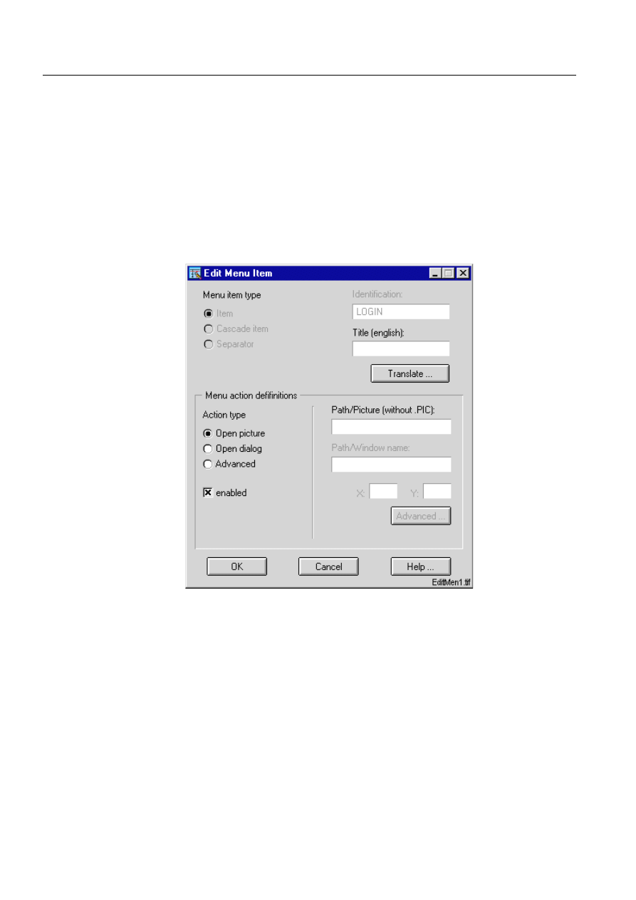
)LJ $GG0HQX,WHPGLDORJ
The menu item type is selected with the available radio buttons. If selected item type
is Item or Cascade item, then the Identification and Title text fields are active and
can be filled in. The Identification field can also be left empty. In that case the
system time is automatically used as an identifier for the item. The identifier has to
be unique within a menu part. The menu action definitions are defined in the Menu
action definition area. The cascade items can be enabled/disabled.
For normal items you can define the action, which is done when the menu item is
selected at runtime. The most common actions can be made by selecting action types
Open picture/Open dialog and filling in the needed details. (NOTE! Picture and
window names can be max. 10 characters, X can be in the range of 0... 80, Y in 0...
48). If you are familiar with SCIL programming language, you can also define the
1MRS751880-MEN
LIB 500
31
LIB 500 Configuration Manual
Configuration Guide
3. Backbone
3
action program in SCIL by selecting the Advanced button. Made changes are saved
with OK and discarded with Cancel.
3.1.3.5.
Functionality of the edit menu item dialog
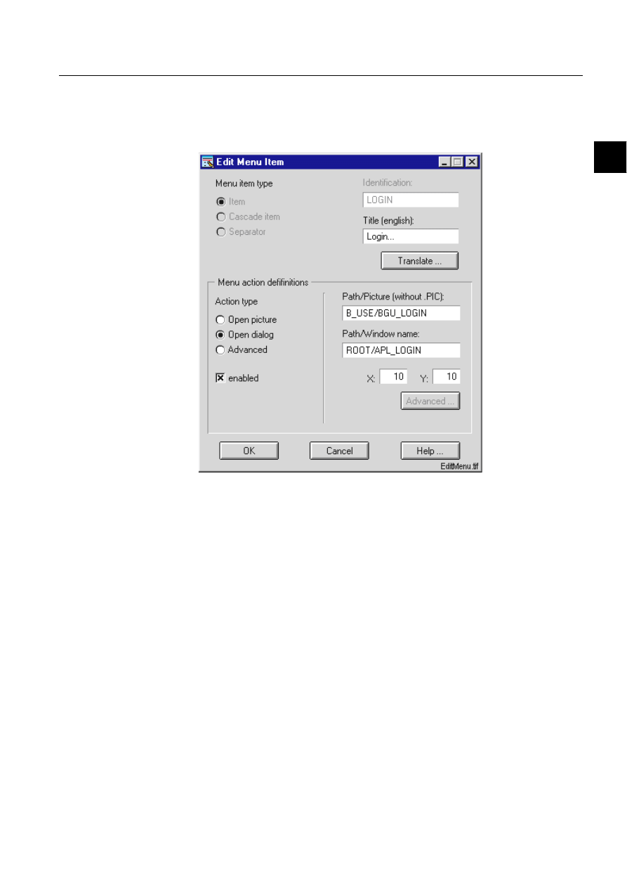
)LJ (GLW0HQX,WHPGLDORJ
The Edit Menu Item dialog is similar to the Add Menu Item dialog, except for that
the current definitions are shown at dialog start-up.
3.1.3.6.
Functionality of the preview dialog
You can open the preview dialog by selecting the Preview button. The dialog
presents the menus currently modified as they are shown at runtime. No menu
actions are performed. The dialog is dynamically updated when changes are made.
The dialog can be closed by clicking the button marked with a cross in the upper
right corner of the dialog.
3.1.4.
Application engineering information
Often in application engineering there is a need to disable/enable menu items
dynamically with SCIL. Therefore, there are methods for doing this in the header.
6&,/PHWKRGIRUGLVDEOLQJDPHQXLWHP
header.set_menu_item_insensitive( %item_identifications)
Where the %item_identifications is a vector of items to be disabled.
32
1MRS751880-MEN
LIB 500 Configuration Manual
LIB 500
3. Backbone
Configuration Guide
6&,/PHWKRGIRUHQDEOLQJDPHQXLWHP
header.set_menu_item_sensitive( %item_ids)
Where the % item_identifications is a vector of items to be enabled.
For menu configurations the language conversions are made with the Menu
Configuration Tool. First create a fully functional menu with one language. The file
holding language depending part of your menu configurations is saved under your
application in .../APLMOD4/LANG’language number’ directory. You can then
copy the file into another .../APLMOD4/LANG’language number’ directory and
open the copied file again with the Menu Configuration Tool (remember to change
your monitor language first). Now you can change the title texts of the menus with
the Edit function of the Menu Configuration Tool.
3.1.5.
Process objects
The base function creates no process objects
3.1.6.
Format pictures
The base function has no format pictures.
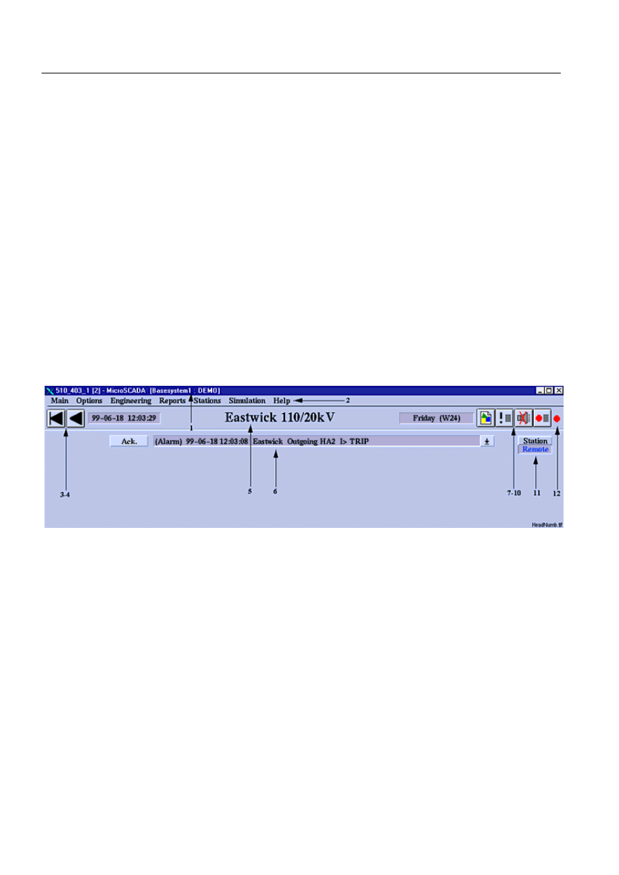
3.2.
Picture header
)LJ 3LFWXUH+HDGHU
1. Computer and user name
2. Drop-down menus
3. First Picture
4. Previous Picture
5. Picture Name
6. Alarm Row
7. Hard Copy
8. Event List
9. Audio Alarm Acknowledgement
10.Alarm List
11.Station Symbol
12.Alarm Indication (blinking)
1MRS751880-MEN
LIB 500
33
LIB 500 Configuration Manual
Configuration Guide
3. Backbone
3
3.2.1.
Picture name
The picture name is configurable via the Standard Configuration Tool in the Picture
Editor. The Picture name is shown in the middle of the header bar.
3.2.2.
Configurable attribute for name of picture header file
A new configurable attribute for the name of the picture header file will be
implemented in the configuration file B_INST/BGI_BASE2.DAT for the standard
base PF of LIB 500 4.0.3. This is made for having the opportunity to assign a certain
header to a certain picture.
For more information on the header, please see the LIB 500 Operator’s Manual
(1MRS751885-MUM), Chapter 2 Backbone.
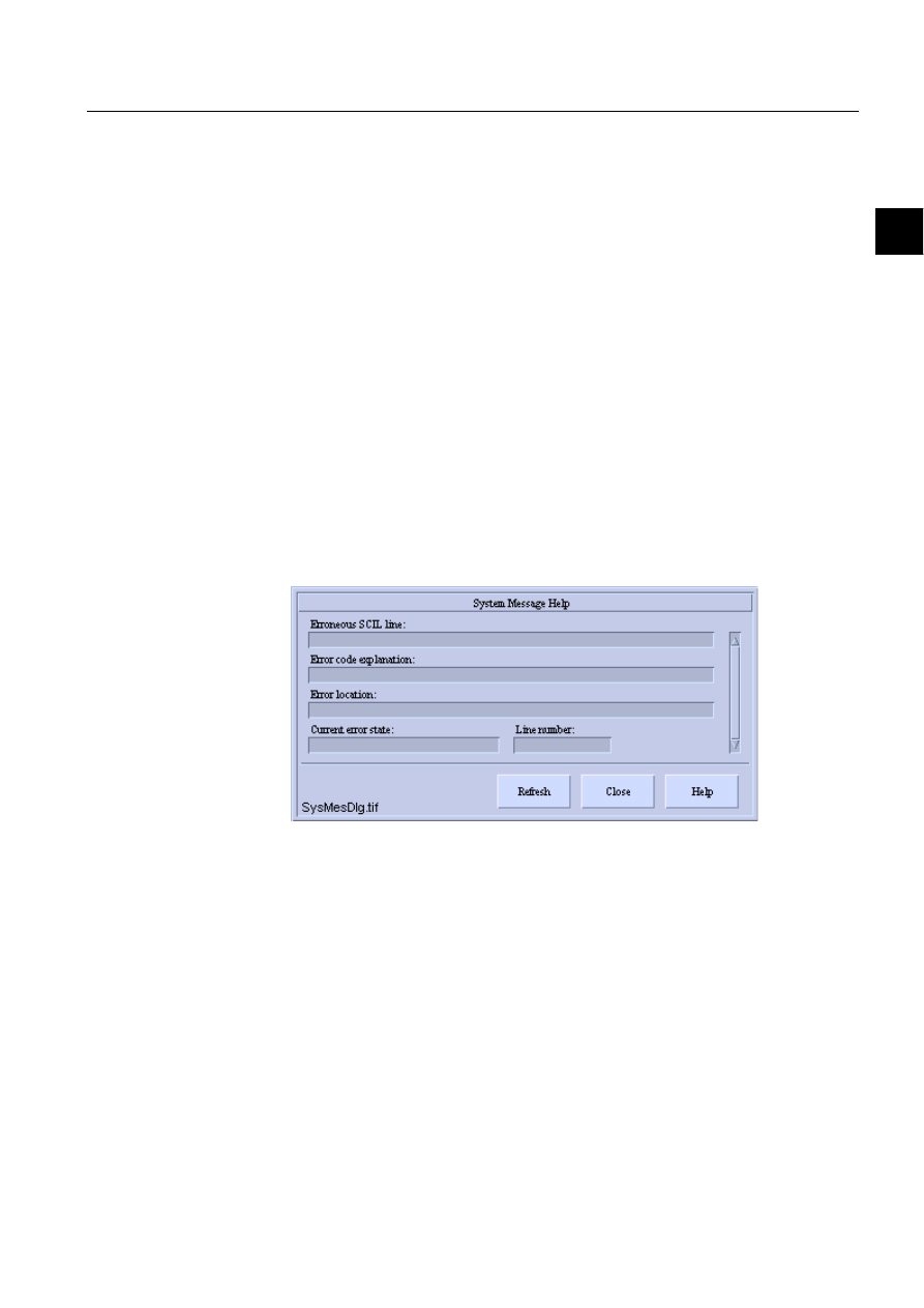
3.3.
On-line system debugging
3.3.1.
System message
The System Message dialog is an aid for system engineering and debugging. When
the dialog is opened, the dialog is updated with information of the SCIL errors
occurred in that picture. If there is more than one SCIL-error, the errors can be
scrolled. The first or oldest error is shown first. If additional errors occur while the
dialog is open, the dialog can be refreshed by clicking the Refresh button.
)LJ
6\VWHP0HVVDJH+HOSGLDORJ
3.4.
Technical architecture in calendar
3.4.1.
Start-up initialization
Calendar objects are initialized by a script saved in the text file bgu_calini.txt. This
script is called from the text file bgu_libc.txt, which is executed every time when an
application goes hot.
3.4.2.
SW interface procedure
SW interface is implemented as a command procedure object. The return value
depends on the arguments given to it.
The first argument of an interface procedure defines the action type that will be
executed.

34
1MRS751880-MEN
LIB 500 Configuration Manual
LIB 500
3. Backbone
Configuration Guide
The following table shows the action types, required parameters and return values:
Arguments are given to the command procedure as per in the following table. The
first argument is always the type of call, 1, 2, 3, 4 or 5. Arguments 2-5 are parameters
that are specific to each call type.
Table 3.4.2-1
The action types, required parameters and return values
Procedure names obtained with call type 1 contain all period names defined in the
calendar. These names can be given as input parameters when called with type 2.
Please note that call type 2 does not allow a text vector the length of which is more
than 32.
Output data is represented by a bit in the output vector of call type 2. For example,
if the presence of periods PERIOD_1 and PERIOD_2 in the calendar is examined,
the input name vector would be (PERIOD_1,PERIOD_2). The output variable
would then contain an integer vector. Every element of this integer vector describes
each ’name status’. The bit 0 (LSB) is the status of PERIOD_1 and the bit 1 is the
status of PERIOD_2, etc. Decoding is thus necessary in the calling procedure. A
maximum of 32 periods can be retrieved at a time (integer represented with 32 bits).
3.4.2.1.
Override policies
Override policy defines how the calendar default day types are applied to output
data. This switch is available in functions 2,3 and 5. If the argument is not given, it
is considered to be 0.
Table 3.4.2.1-1
Override Policies
Interface procedure uses another procedure named BGU_CALMP that scans the
database and updates the file named PERIODS.DAT, which is located in the PICT
logical directory. The file is a list dump that contains information about calendar
periods. A new scan is performed, if the parameter period_file_valid is 0 in the
Argument 1,
action type
Argument 2 Argument 3 Argument 4 Argument 5
Argument 6
Return value
1
-
-
-
-
-
Defined period names, text vector
2 Start
time
(SCIL
format)
Stop time
(SCIL format)
Interval in
seconds
Period
names, text
vector
Override
policy, 0-2
Integer vector, each bit represents
period status
3 Time
(SCIL
format)
Period name,
text string
Override
policy, 0-2
-
-
TRUE/FALSE status of the period
at a given time
4
-
-
-
-
-
Defined day types in the calendar,
text vector
5 Start
time
(SCIL
format)
Stop time
(SCIL format)
Day type
names, text
vector
Override
policy, 0-2
-
Integer vector, each bit represents
the day type status
Override policy
Meaning
0
Defaults as defined in the calendar
1
Any day type overrides the default day type
2
Default day types ignored, even if defined in the calendar

1MRS751880-MEN
LIB 500
35
LIB 500 Configuration Manual
Configuration Guide
3. Backbone
3
calendar.ini file. If the parameter is 1, the dump file is evaluated and output as a
return value. After the dump is updated, the procedure marks this parameter to 1.
The parameter is set to 0, if editions are made in the calendar HSI. The purpose of
this procedure is to speed up interface calls to the calendar database. There is no need
to explicitly call this procedure.
bgu_calmp:c Return value: list
Table 3.4.2.1-2
Attributes
3.4.3.
Time channels
Time channels are used to launch next timed procedure in the calendar. Two time
channels are maintained because a command procedure cannot set the execution
time of launching time channel. The time channels are modified turn by turn by the
BGU_CALTC1:C and BGU_CALTC2:C command procedures. When the
command procedure BGU_CALTC1:C is launched by the time channel
BGU_CALTC1:T, the time channel BGU_CALTC2:T is initialized to the next time
point defined in the calendar. The time channel BGU_CALTC2:T launches a
command procedure BGU_CALTC2:C which is identical to BGU_CALTC1:C
except for one line (line no. 20), which contains a variable to identify the other time
channel/command procedure set. In turn, BGU_CALTC2:C initializes
BGU_CALTC1:T.
Startup initialization of the time channels is performed by calling the command
procedure BGU_CALINI.TXT, which is run in application initialization time and
every time the calendar is started.
When a command is executed by the calendar, a message is displayed in the
MicroSCADA notification window. If errors occur while executing the program, a
message will appear in the MicroSCADA notification window:
<date> <time> <command procedure> command failed.
Please note: If a procedure that is run by the calendar
a) generates an error with the command #error raise or
b) turns on error handler with the command #error stop and an error occurs, the
procedure timing system stops. If this happens, restart the timing system by opening
the calendar. When the calendar dialog will be closed again, the time channels are
initialized. A message is displayed in the MicroSCADA notification window when
the initialization takes place.
Attribute Meaning
ty
type of time period: 1=conventional period, 4=in-day period ALWAYS 1!
tm
time, SCIL format
nm name
of
period
ns
new state of period, 1=on 0=off
nv
name value 2** ([count of period name]-1) NOT IN USE
pn
NOT IN USE
pt
NOT IN USE

36
1MRS751880-MEN
LIB 500 Configuration Manual
LIB 500
3. Backbone
Configuration Guide
3.4.4.
Calendar file structure
Calendar data is stored in vector dump files. When data is loaded, the whole file is
read to a vector. Every year has a file of its own. Day types are saved in a separate
file. The data vector includes nested vectors: every item is a vector containing one
block. Block is one attribute data item that is defined for a day or a day type. Block
includes a label and a vector that contain attribute parameters. One day or day type
can have several blocks in the dump file.
Every year that has defined day attributes has a file of its own which is named
y????.dat, where four question marks represent the year number, for example 1998.
Day types are saved in a separate file named daytypes.dat. All the files have the same
data format. The only difference to year data is that in the day type data the date is
replaced by a day type label.
The files (year files and day type file) are saved in logical directory PICT.
Because the data is separated into several files by the year, it is possible to remove
unnecessary year data simply by deleting the corresponding files without affecting
the old day type settings. When the files are deleted, these years are shown without
any settings when they are browsed in the calendar view.
Interface procedure code is saved in the BBONE directory in the file bgu_calen.txt.
The procedure is initialized by calendar startup by BGU_CALINI.TXT. Interface
procedure remains in memory and is thus available for other procedures even if the
calendar is closed. The interface procedure status is checked every time the calendar
is started.
Table 3.4.4-1
The following files are used by the calendar
The following objects are defined/used by the calendar, and should be present when
the calendar is started the first time. The files that appear both in the bbone and in
File Directory
Meaning
cal_1.vso
bbone
File containing HMI components
bgu_calen.txt
bbone
File containing interface procedure code
bgu_calmp.txt
bbone
File containing period update procedure code
bgu_caltc.txt
bbone
Code for bgu_caltc1 and 2
bgu_calini.txt
bbone
Initialize calendar objects at application start time
bgu_cala.hlp
lang0,lang1,...
Help file of the main calendar view
bgu_calb.hlp
lang0,lang1,...
Help file of attribute tool
bgu_calc.hlp
lang0,lang1,...
Help file of options tool
cal_1.ini
bbone, pict
General settings of the calendar
daytypes.dat
bbone, pict
Database file containing day type data
cal_proc.dat
bbone, pict
Procedure timing information
periods.dat
bbone, pict
Calendar data periods
calgen.dat
bbone, pict
Dump of list containing general data vectors
ynnnn.dat
pict
Database files containing day data of year nnnn
bgu_cal.log
pict
Log file about commands ran by the calendar

1MRS751880-MEN
LIB 500
37
LIB 500 Configuration Manual
Configuration Guide
3. Backbone
3
the pict logical directories contain application specific data. The version in the bbone
is the original that is copied to the pict -directory at startup to make default settings.
Table 3.4.4-2
The objects that are defined/used by the calendar and should
be present when the calendar is started the first time
3.4.5.
Calendar internal data format
Calendar data is saved as vector dump for each year. Additionally, there is a file that
contains definitions of the day types. All these files have the same internal data
format. Data is saved in these files as one vector that includes a nested vector for
each definition block. One day or day type can have several definition blocks. Date
string is used as a search key in year files and day type name (string) is used as a
search key in the day type file. Search key is the first element of the nested vector.
The second element indicates the type of the definition block.
Table 3.4.5-1
The following definition block types are available
All element data types are TEXT unless otherwise stated.
!
Daylight saving time implementation is not available in the first version. The
daylight saving time operations (actual time change and the status of current time
status checking) are supposed to be managed with standard calendar features. Use
command procedure launching to make the system time change and long period
feature to define standard/daylight saving time periods.
Object Type
Meaning
bgu_calen
c
Calendar interface procedure
bgu_calmp
c
Procedure for period file update
bgu_caltc1
c
Find next proc. and init bgu_caltc2
bgu_caltc2
c
Find next proc. and init bgu_caltc1
bgu_caltc1
t
Time channel used by the calendar
bgu_caltc2
t
Time channel used by the calendar
Element of nested vector
Element 2, block type
Element 3
Element 4
Element 5
1, Period start/stop
Period point type
(integer) 1=start,
0=stop
Period name
Start/stop time
2, Day name
Day name
Marking (integer) 1=on,
0=off
Color
3, Run procedure
Running time
Procedure name
-
4, In-day period
Period name
Start time
Stop time
5, Type assignment
Type name
-
-
6, Daylight saving time
Time of day
adjust type:
1=daylight saving time,
2=standard time
-

38
1MRS751880-MEN
LIB 500 Configuration Manual
LIB 500
3. Backbone
Configuration Guide
3.4.6.
User specific modifications
3.4.6.1.
Making a new attribute block type
Adding new attribute type is a possibility to enhance the functionality of the
calendar. New attributes can be added to days and day types.
1. Make a new VS_CONTAINER of size w=300, h=100.
2. Define the following properties in the container init method using the .modify
command:
• attribute_count (integer). Set this variable to a value representing the actual
parameter count included in the attribute.
• attribute_values (vector). This can be set as an empty vector in the init method. *
type. This property can be set to 0. This property is used by the calendar and
should not be used within the block functions.
• edited. This property must be set to 1 any time the block contents is changed.
Write the code that sets this to 1 when any control is edited in the block.
• marked. Make a check box to the upper right corner of the block. Write the code
that updates this property to 1 when the box is crossed and to 0 when the box is
cleared. Used to mark the block for deletion
• Example: .modify this=list(attribute_count = 1,-attribute_values=vector(),
type=0, edited=0, marked=0)
3. Add user interface components to the container and define the appropriate
functionality.
4. Add a short description to the attribute_types vector in the .init method of the
calendar main view object (VS_MAIN_DIALOG). This text will appear in the
list box of attribute selection dialog box. Do not remove or change the order of
the existing elements of the vector.
5. Add the container name to the attr_block_names vector of the main dialog
object. The name must be in the same index number as the description is in the
attribute_types vector. Do not remove or change the order of the existing
elements of the vector.
6. Create a new method named update_vector to the container. Write here
commands that
a) update user interface object states to the attribute_values vector (argument(1)=1)
b) initialize the container when previously saved data is loaded (argument(1)=0).
This method is called with argument 1 by the calendar before the attribute_values of
the container are to be updated in .attribute_values member variable and saved with
calendar data, and with argument 0 when container is initialized (.attribute_values
member variable should contain the initialization data before calling the method).
When called with argument 1, the method should return TRUE if dialog object
values are valid and FALSE if they are not. Example:
#if argument(1)==0 #then #block
;Initialize UI objects:
#block_end
#if argument(1)==1 #then #block
;Write UI object states to .attribute_values
#return TRUE ;if data is valid, or FALSE if it is not.
#block_end

1MRS751880-MEN
LIB 500
39
LIB 500 Configuration Manual
Configuration Guide
3. Backbone
3
7. Add functionality that updates the edited property after editions. This property
indicates the calendar main window when to save day/day type settings. Set the
edited property to 1 when the user makes edit operations in the block. Setting of
this property can be done in notify method of each user interface object included
in the container. If you do not set the edit property, editions are discarded when
the user moves to another day or day type in the calendar without closing the
attribute dialog.
8. Add public method named on_delete. This method must exist but it does not
have to have functionality. The method is executed when the block is deleted by
using the attribute tool.
9. Add check-box to the container and add functionality that updates the marked
property of the container every time the check-box state is changed. When the
check-box is crossed, the marked property should be 1 and when it is empty, the
property should be 0. Please refer to the existing blocks for help to this. The
property is used to mark blocks for deletion in the attribute dialog.
!
To utilize the data that your block maintains, make command procedures of your
own that perform the database calls. Do not modify the existing calendar interface
procedure. Please refer to the calendar database format description elsewhere in this
document.
3.4.7.
Actions in error conditions
If errors occur and closing and reopening the calendar dialog does not help, try to
delete all calendar command procedures and time channels. Start the calendar again
to recreate the objects. If the calendar is not started after deleting the objects, the
command procedure timing does not work and the calendar interface procedure is
not available.
If calendar operations are very slow, try to move unnecessary year data (past years)
into another location. This data is in year files, y
QQQQ.dat, QQQQ represents the year
number.
It is possible to remove calendar installation in the following way: Delete all
calendar .dat files and the .ini file in the PICT directory (logical directory that
depends on application. Please see MicroSCADA manuals for more information).
Note: all data defined in the calendar is deleted.
cal_1.ini
daytypes.dat
periods.dat
calgen.dat
cal_proc.dat
y
QQQQ.dat (where QQQQ is year number, for example y1998.dat)
Calendar installation is recreated when the calendar is started again.

40
1MRS751880-MEN
LIB 500 Configuration Manual
LIB 500
3. Backbone
Configuration Guide
3.4.8.
Restrictions
Interface procedure limits:
• Count of starting and ending points of calendar periods is limited to 10000.
• Maximum count of period names: 10000
If a large amount of day attribute definitions are made, the database operations will
significantly slow down.

1MRS751880-MEN
LIB 500
41
LIB 500 Configuration Manual
Configuration Guide
4. Event list
4
4. Event
list
4.1.
General
4.1.1.
Purpose and description
The purpose with the Event List is to provide the user with information about events
occurring in the system. Thus the user can make the right decisions and verify that
taken measures are successfully performed. It is also possible to receive information
about activities carried out by other users, operations of objects, acknowledging of
alarms, editing of limit values, logging in etc.
The Event List presents the data in a structured way, for the convenience of the user.
Each event is normally presented by displaying an event text line which describes
the cause of the event in the process.
Event text lines normally consist of a time stamp, object identification, a signal text
and a text indicating the status.
4.1.2.
Features/options
• Event List layout can be configured. There can be even more than 80 characters
per line
• Printouts can also be configured to contain more than the standard 80 characters
per line
• Scroll interval configurable from 10 pages to 100 pages. in steps of 10.
• Fast navigation in the list by using; jump to the last page, one page back or
forward, or one interval backwards by using the scrollbar
• Possibility to navigate to previous day/next day or to day typed into input dialog
• User-friendly filters
• Updating/Frozen presentation modes
• Authorization support
• Help in all dialogs
• Additional comments can be given to the events, up to 250 characters per event
• Event Reports to printer on demand
• Possibility to display events either in log or event order
1MRS751880-MEN
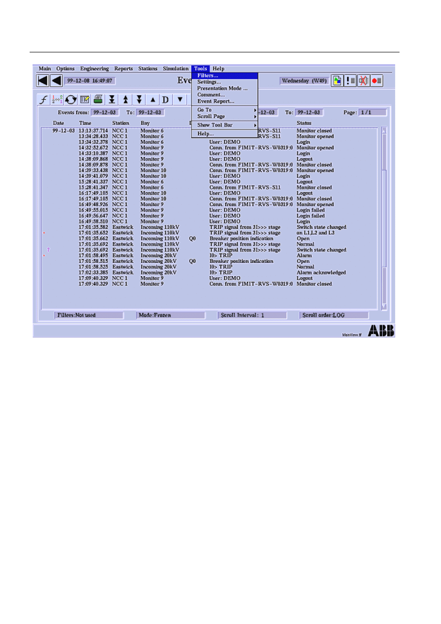
42
1MRS751880-MEN
LIB 500 Configuration Manual
LIB 500
4. Event list
Configuration Guide
)LJ
(YHQW/LVWPDLQYLHZ
4.1.3.
System requirements
• MicroSCADA 8.4.3
• Backbone of LIB 500 4.0.3
4.2.
Events
Event is a wide term that also comprises alarm. The event activation and
consequential actions are defined in the process database separately for each
individual object.
Typical examples of events are:
• Change or updating of an object value
• Change of alarm and warning state
• Change of reliability stamp
• Change of the alarm definition, alarm blocking, acknowledgement etc.
When an event occurs in the system, the operator wants to receive an answer to the
following questions; (answers provided below each question)

1MRS751880-MEN
LIB 500
43
LIB 500 Configuration Manual
Configuration Guide
4. Event list
4
1. What happened?
Change of the state of the object or an executed operation.
2. Where did it happen?
A descriptive text (object identification, OI and object text, OX) comprising e.g. a
device notation and the type of object or operation.
3. When did it happen?
The point of time when the event occurred. If the event originates from a station
providing a time stamp, this time stamp is used. Depending on the station, the time
is on second or millisecond level. In other cases, the time stamp is the MicroSCADA
system time with an accuracy of 10 milliseconds.
4.2.1.
Event functions
The following functions can be activated by an event:
• Updating monitor pictures
• Automatic printout. Like alarms, events can cause automatic printouts on the
event and alarm printer
• Registration is made in the history buffer, and in connection to this also in the
Event List
• Activation in the report database, e.g. automatic control operations, registration,
report printout, etc.
4.2.2.
Event activation
Depending on how crucial an object is, the following events in the object may
activate an event printout, a registration in the history buffer, or an activity in the
report database (from the least to the most crucial object):
• No activation
• An alarm is activated and deactivated
• The alarm or warning state changes
• The object value changes
• The object value is updated, although it is not changed
4.2.2.1.
Preventing the printing of events
Those process objects, the value of which changes frequently, e.g. earth fault, results
in massive reporting of events to the Event List. To prevent unnecessary reporting
of process object values to the Event List, as well as their printing to the printer, take
the following steps:
1. Set the value of the process object attribute Alarm Class, AC, to higher than 0
2. Set the Alarm Delay, AD attribute, to some seconds, e.g. 10
3. Set the History Activation, HA attribute, to Alarm by setting HA to 0
4. Set the Printout Activation, PA attribute, to Alarm by setting PA to 0
The attributes are changed by the means of the Object Navigator, which is found in
the Application Object Tab available in the Tool Manager. Changes can be made by
LEC when commissioning the Event List.

44
1MRS751880-MEN
LIB 500 Configuration Manual
LIB 500
4. Event list
Configuration Guide
In the Object Navigator, select the application, and then select the process object
concerned. By clicking the PO once, the corresponding indexes are listed. The
attribute settings for the indexes become available by double clicking the index.
Make changes according to the instructions given above.
No event is registered if the value exceeds the alarm limit for less than 10 seconds’
time. If the value exceeds the alarm limit for more than 10 seconds, an event and an
alarm together with the right time stamp are registered.
4.2.3.
User authorization
The default authorization group for the Event List is Event_Handling.
Table 4.2.3-1
The authorization group consists of the following three levels
4.3.
Application engineering information
Before you can take the Event List into use, some preparations are required. If you
intend to upgrade an Event List of an earlier version to this LIB 500 4.0.3 Event List
v. 2.4, there are also some measures to be taken. The procedure for converting the
Event List (LOG files) made with earlier versions to the new History Database,
HDB, format is also described. The conversion can also be done after the new Event
List has been taken into use.
Action 1 described in the following section, Base system configuration, is always
obligatory, also when installing the Event List to a system where no Event List has
been used before. Action 2 is not compulsory, but recommended when upgrading
the Event List.
4.3.1.
Base system configuration
4.3.2.
General
An application may choose between the old event log/history buffer scheme and the
new history database scheme.
7KH/,%(YHQW/LVWYGRHVKRZHYHU
VXSSRUWRQO\+'%ILOHV
A new application object attribute HP (History logging Policy) is introduced:
Table 4.3.2-1
HP History logging Policy
For compatibility, the default value is "EVENT_LOG".
Auth. level (min.)
Operations allowed
Engineering (2)
Editing station and bay lists of the filters
Control (1)
Select filters
View (0)
All other operations
Value Text
value
"DATABASE"
selects the new database scheme
"EVENT_LOG"
selects the old event log scheme
"NONE"
no event logging is done

1MRS751880-MEN
LIB 500
45
LIB 500 Configuration Manual
Configuration Guide
4. Event list
4
If HP == "DATABASE", the attribute HB (History Buffer length) does not have any
meaning.
When HP == "DATABASE", the application attribute HT is incremented every time
an event is written into the history database.
4.3.2.1.
Action 1
Preparation always needed before taking Event List v. 2.4 in LIB 500 4.0.3 into use
for the first time:
The application attribute HP has to be set to "DATABASE" in
SYS_BASCON.COM before application start up.
4.3.2.2.
Action 2
When upgrading a system using an Event List previous to Event List v. 2.4 in LIB
500 4.0.3, the printer object that promotes the creation of log files is recommended
to be taken out of use, when the HDB files are used.
4.3.3.
Configuration of process objects
The history database requires no special configuration of process objects. Attribute
HL has no meaning if APL:BHP == "DATABASE".
4.3.4.
Converting event LOG files to HDB files
The format for storing events has changed from log files used in previous versions
of the Event List to History Database, HDB, files. These log files are no longer
supported by the Event List, because the log files are not compatible with the HDB
files. Without conversion, this means that only events received after installation of
the Event List can be displayed. Still the log files can be taken into use again by a
conversion made from log to HDB files. This conversion can be done whenever
needed.
The log files are sequential, thereby generally having a long access time. The history
database consists of history database files each containing events on day by day
basis. The files are named according to the date as APL_yymmdd. PHD, for
example file APL_980115.PHD contains the events logged on 15-Jan-1998. The
files are stored in the directory C:/SC/APL/nnn/APL_, where nnn is the name of the
application.
For fast access in time stamp order, there is an index file corresponding each data
file. The name extension of the index file is PHI.
4.3.4.1.
Converting procedure
There is a SCIL program available which performs the conversion. The only
preparation it needs is to define the start and end date for the events to convert. The
program takes care of the rest, for instance, generating HDB files inserted into the
application. The log files are still available after the conversion.
The program is named
%(8B(&7;7 and is located in 6&/,%%$6(
(9(1786(. This program is run from the TEST DIALOG program.
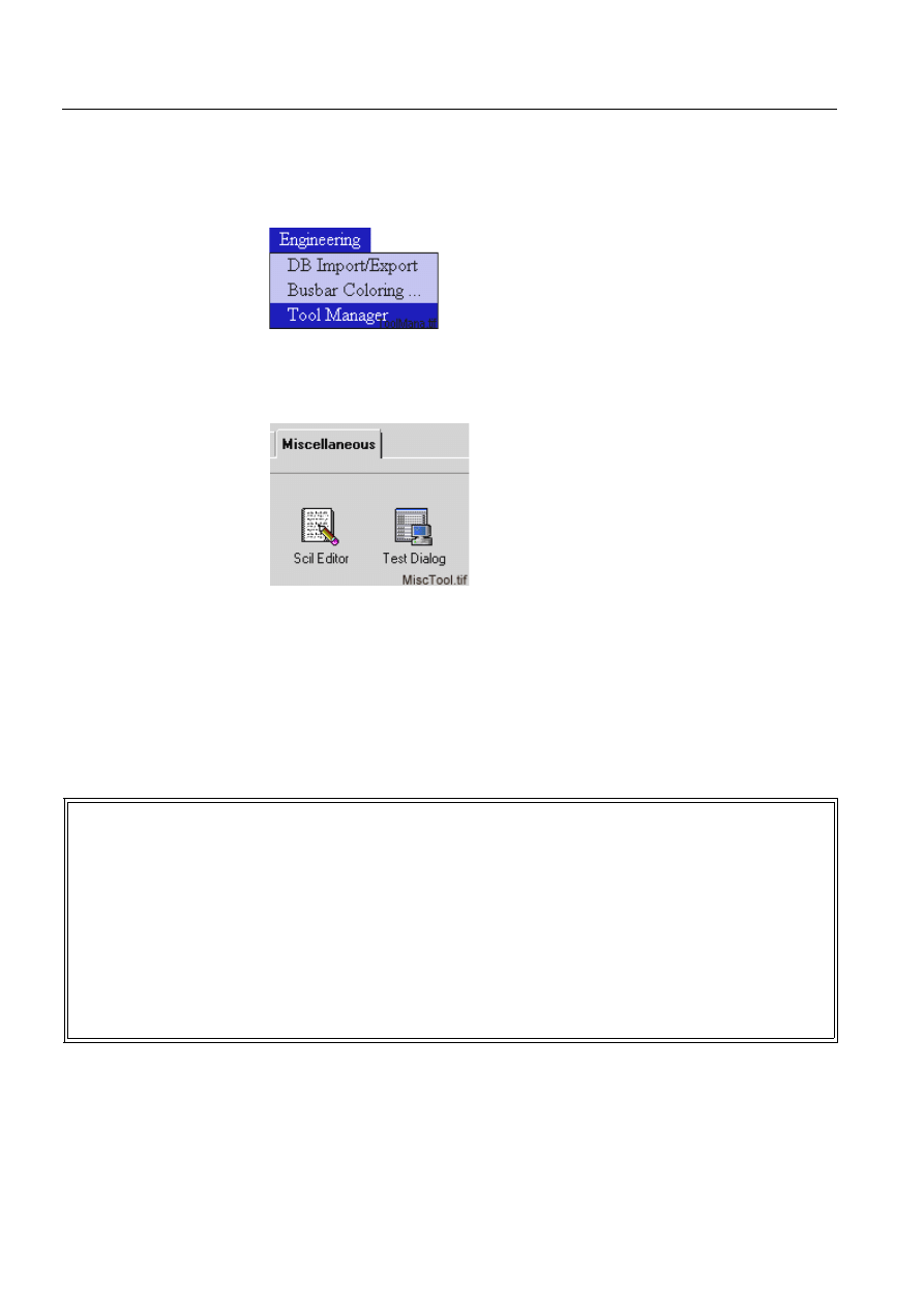
46
1MRS751880-MEN
LIB 500 Configuration Manual
LIB 500
4. Event list
Configuration Guide
The program can be edited by any ASCII format editor or by the SCIL editor
provided by the MICROSCADA Tool Manager.
1. Start from the Engineering menu and select Tool Manager, which starts the
MICROSCADA Tool Manager
)LJ 6HOHFW7RRO0DQDJHU
2. Select the SCIL editor from the Miscellaneous folder in the Tool Manager to
modify the file BEU_EC.TXT, see path above
)LJ 7KH6&,/(GLWRUDQGWKH7HVW'LDORJWRROVVWDUWE\GRXEOHFOLFNLQJ
3. A) Edit the BEU_EC.TXT file, by giving the start and end date for the events to
be converted.
The format is
\HDUPRQWKGDWHKRXUPLQXWHVHFRQGV.
B) The name of the application has to be given. Replace
11111, see (see
'RQRWPDNHDQ\RWKHUFKDQJHV
)LJ 7KHXVHUHGLWDEOHSDUWLQWKH%(8B(&7;7ILOHLQ6&/,%%$6((9(1786(
After saving the changes, run the program from the TEST DIALOG.
4. Type the following in the Test Dialog
;Description : This is the program for the Event Converter
;-----------------------------------------------------------------------
;-----------------------------------------------------------------------
;User_defined_variables_begin
;In
@e_start_date = pack_time(1998,2,25,0,0,0);time date for the first log file to handle
@e_end_date = pack_time(1998,3,3,0,0,0) ;time date for the latest log file to handle
@t_log_int = "DAY"
;text interval for the log files
@i_log_prn = 15
;integer the number of the used log files
#path t_log_dir +c:/sc/apl/NNNNN/pict, NO_CREATE ;text the path for the log files
;User_defined_variables_end
;-----------------------------------------------------------------------
;-----------------------------------------------------------------------
;NOTE Do not change the following sections !
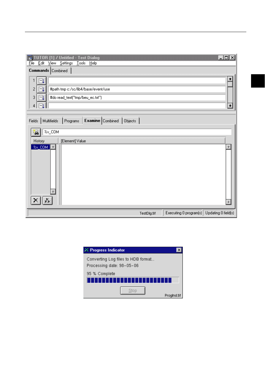
1MRS751880-MEN
LIB 500
47
LIB 500 Configuration Manual
Configuration Guide
4. Event list
4
#path tmp c:/sc/lib4/base/event/use
#do read_text("tmp/beu_ec.txt")
5. Press the button to the left to execute the conversion.
)LJ *LYLQJWKHFRPPDQGVLQWKHWHVWGLDORJ
The conversion progress is showed with a progress indicator. The date of the events
being processed is presented.
)LJ 7KHFRQYHUVLRQSURJUHVVLQGLFDWRU

48
1MRS751880-MEN
LIB 500 Configuration Manual
LIB 500
4. Event list
Configuration Guide
7KH6723IXQFWLRQLVGLVDEOHGRQSXUSRVH
After the conversion is performed, the new HDB files are automatically taken into
use by the Event List. The conversion is done once.
5HPDUNV
The time needed for the conversion is directly proportional to the amount of LOG
files and number of events. Therefore, the conversion (depending on case) takes
time.
The Test Dialog cannot be use for other purposes when it is converting the LOG files
to HDB files If the Test Dialog is needed during the conversion, open another Tests
Dialog.
4.3.5.
Pictures used by the event list
Table 4.3.5-1
The pictures located in the LIB4/BASE/EVENT/USE directory
Picture Functionality
BEU_CMDLGA.PIC
Comment dialog main picture
BEU_EVENTS.PIC
Event List Main picture
BEUICOCOMM.PIC
Toolbar icon to open the comment dialog
BEUICOFILT.PIC
Toolbar icon to open the filters dialog
BEUICOFIRS.PIC
Toolbar icon to show the latest events
BEUICOFROZ.PIC
Toolbar icon to open the presentation mode dialog
BEUICOHELP.PIC
Toolbar icon to open the help viewer
BEUICOPDOW.PIC
Toolbar icon scroll one page down
BEUICOPINT.PIC
Toolbar icon scroll one interval back
BEUICOPRIN.PIC
Toolbar icon to open event reports print dialog
BEUICOPUP.PIC
Toolbar icon scroll one page up
BEUICOSETT.PIC
Toolbar icon to open the setting dialog
BEU_MODEA.PIC
Presentation mode dialog picture
BEU_PRINTA.PIC
Event reports print dialog main picture
BEU_SETTA.PIC
Setting dialog main picture
BEU_SETTB.PIC
Setting dialog subpicture
BEU_SETTB1.PIC
Setting dialog subpicture
BEU_SETTBA.PIC
Setting dialog subpicture
BEU_SETTBB.PIC
Setting dialog subpicture
BEU_SETTBC.PIC
Setting dialog subpicture
BEU_SETTC.PIC
Setting dialog subpicture
BEU_SETTCA.PIC
Setting dialog subpicture
BEU_SETTCB.PIC
Setting dialog subpicture
BEU_SETTD.PIC
Setting dialog subpicture
B_EVENT.PIC
This file holds the Status sign for the event row

1MRS751880-MEN
LIB 500
49
LIB 500 Configuration Manual
Configuration Guide
4. Event list
4
Table 4.3.5-2
The text files located in the LIB4/BASE/EVENT/LANG0
directory
4.3.6.
Help text files
Table 4.3.6-1
The help files located in the LIB4/BASE/EVENT/LANG0
directory
4.3.7.
Other text files
Table 4.3.7-1
The text files located in the LIB4/BASE/EVENT/USE directory
FORM4B_EPR.PIC
Used for printing headers in the events reports
FORM4B_SER.PIC
This form picture is presented when acknowledging alarms etc.
FORM4B_UNI.PIC
This form picture is used if no form is specified for the database
Picture Functionality
Text file
Functionality
BEU_CMDLGA.TXT
Text file that holds the phrases used in the comment dialog
BEU_EVENTS.TXT
Text file that holds the phrases used in the list
BEU_EVENTS.TXT
Text file that holds the phrases used in the list
BEU_PRINTA.TXT
Text file that holds the phrases used in the Event Reports print
dialog
FORM4B_SER.TXT
Text file that holds the phrases used in the Service form picture
FORM4B_UNI.TXT
Text file that holds the phrases used in the Universal form
picture
Help file
Functionality
BEU_CMDLGA.HLP
Help texts for the Comment dialog
BEU_EVENTS.HLP
Help texts for the Event List
BEU_FILTER.HLP
Help texts for the Filters dialog
BEU_MODEA.HLP
Help texts for the Presentation mode dialog
BEU_PRINTA.HLP
Help texts for the Event Reports Print dialog
BEU_SETTA.HLP
Help texts for the Setting picture
Text file
Functionality
BEU_FILNME.TXT
Text file for the filter conditions (must be edited in the filters
dialog)
BEU_C_PART.TXT
Text file holding the column settings (must be edited in the
Setting dialog)
BEU_SET.TXT
Text file holding the Event List settings
BEU_TRPRI.TXT
Text file that holds the transparent printout settings point.
The file BEU_TRPRI.TXT is no longer included in the Event
List. It has been replaced by xxx which is located in the
Backbone.
xxxx
This file can be edited in order to change the printing settings.
It contains advice on how to modify.

50
1MRS751880-MEN
LIB 500 Configuration Manual
LIB 500
4. Event list
Configuration Guide
4.3.8.
The process objects
The HL-attribute of the process objects enables the history logging. The history log
activation follows the history activation (HE, HA, HF). The value of the HL-
attribute should be "BIT_MASK(15)". The HL-attribute is automatically defined for
process objects created by LIB 500 and for process objects created with the
MicroSCADA Process Object Tool.
4.3.9.
Configuring object status indicators
In Event List 2.4 it is possible to configure alarm indicator and object status symbol
to be displayed concurrently. It is also possible to set display priority of alarm
indicator and object status symbol. The configuration is made by editing Event List
configuration file BEU_USRSET.TXT in PICT directory of the application. The
object status handling is defined by attribute PRIORITY in the configuration file.
The following values can be set to the attribute:
Table 4.3.9-1
Attribute values
Example of the configuration file contents:
LIST(AUTH_GROUP="EVENT_HANDLING",COLOR=14,DAY_BREAK=TRUE,FONT=2,-
FROZEN_ORDER="LOG",INT_DAYS=1,INT_LENGTH=128,INT_PAGES=50,LOG_TIME_OUT=30,-
LOOKUP_DAYS=1,PRIORITY="",SCROLL_MODE="AUTO",SHOW_TOOLS=TRUE,TIME_SCROLL=TRU
E)
If the attribute PRIORITY is not defined in the file, default value ("") is applied.
4.3.10.
Configuring OI columns
Single object identifier column is used as default in Event List. The default
configuration can be changed in Common columns sheet of Settings dialog. A
column for each OI field is available. To take the columns in use, follow these steps:
1. Replace existing OI column setting with column "Object ID 1" and write
appropriate column label
2. Increase the column count so that it is possible to configure necessary amount of
OI columns
3. Configure rest of the OI columns
Note that the "Show OI fields" configuration in Backbone Settings is applied only
to standard OI column. If separate OI columns are in use, they are displayed
regardless of the Backbone settings.
4.3.11.
Event specific texts
Event specific texts (event status texts) are defined in form pictures. When event
status text needs to be displayed, the form picture start program is executed. In start
program, a variable containing the event text is initialised. The variable name is
Setting
Meaning
PRIORITY=""
Functionality as in former versions
PRIORITY="OS"
Object status overrides alarm indication
PRIORITY="BOTH"
A
larm indicator and object status symbol are
displayed in separate columns

1MRS751880-MEN
LIB 500
51
LIB 500 Configuration Manual
Configuration Guide
4. Event list
4
%EVENT. Data type of the variable is TEXT. Usually the value of variable is
selected from a list variable that contains several texts to select according the values
and states of process object. It is good practice to initialise the %EVENT variable
with some general text before the actual status text is solved in SCIL code. This
prevents empty line or event data without status text as well as error messages
appearing in the list if the solving for the status text fails. For example:
@EVENT="Changed"
#error ignore
@EVENT=... ;Actual status text solving
#error stop
The status text is solved dynamically each time when the event data is displayed.
The changes made in the form picture files affect all the events that use the form
picture. PF attribute of the process object defines which form picture is used when
displaying the event.

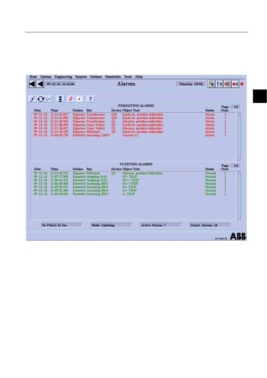
1MRS751880-MEN
LIB 500
53
LIB 500 Configuration Manual
Configuration Guide
5. Alarm list
5
5. Alarm
list
5.1.
General
5.1.1.
Overview
)LJ
$ODUP/LVW7HPSODWH
1MRS751880-MEN
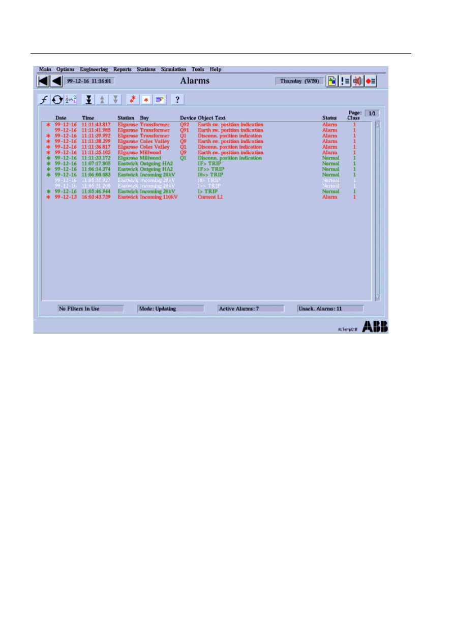
54
1MRS751880-MEN
LIB 500 Configuration Manual
LIB 500
5. Alarm list
Configuration Guide
)LJ
$ODUP/LVW7HPSODWH
5.1.1.1.
Description
The Alarm List within LIB 500 Applications displays a summary of the present
alarm situation of the supervised process. Each alarm is normally presented as an
alarm text line, which describes the cause of the alarm in the process. The alarm text
line normally consists of a time stamp, an object id, an object text, a text indicating
the alarm status as well as a number ranging from 1-7 indicating the alarm class.
Information on the Alarm List is also available in the LIB 500 Operator’s Manual,
Chapter 4 Alarm List.
5.1.1.2.
Features/options
• Two types of Alarm List templates
• User-friendly filters
• Alarm List setting tool for colors and text layout
• Updating/Frozen presentation modes
• Alarm acknowledgement
• Alarm reset function
• Authorization support
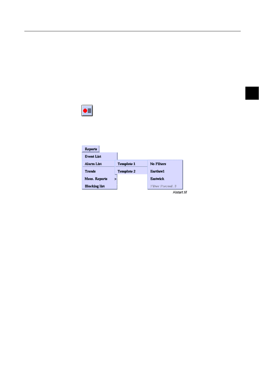
1MRS751880-MEN
LIB 500
55
LIB 500 Configuration Manual
Configuration Guide
5. Alarm list
5
• Help in all dialogs
• Visible Alarm Class
5.2.
General functionality
This chapter describes the alarm handling mechanism of the process database, the
functionality of the LIB 500 Alarm List and the way in which the alarms are
presented on the list.
There are two ways to start the Alarm List, and the Alarm List works differently
depending on where it is started from. If the Alarm List is started by clicking the
Alarm List button
all alarms and classes are shown.
If it is started by selecting REPORTS/Alarm List/Template, filters can also be used.
When using filters, only alarms belonging to the filter configuration are shown.
)LJ $ODUP/LVWVWDUWHGIURPWKH5HSRUWVPHQX
5.2.1.
Selecting objects to the filter configuration
The structure of the filters is such that each station name is given a group of bay
names and each bay is given a group of device names etc. Since the structure is
hierarchical, e.g. station, bay, device, where one station may contain one or several
bays, which, in turn, may contain several devices. By default, only the “all” options
exist, other names must be fetched from the process database.
In the Filters dialog (see Fig. 5.2.1.-1), clicking the Edit button on the right side of
any sensitive object identification combo box opens the Edit dialog, e.g. Edit device,
(see Fig. 5.2.1.-2). The label of the OI field to be edited (e.g. device) is set to the title
of the dialog. The selections at higher levels in the structure are shown in the upper
part of the dialog. The Edit dialog has two lists, the one on the left shows the names
fetched from the process database, and the one on the right shows the names selected
to be included in the main dialog list.
The buttons have the following functionality: the Search button starts a database
query of the station names. A dialog is shown to confirm the operation since it
requires a lot of processor time. Before the station names are brought to the list on
the left they are sorted into an alphabetical order and duplicate names are removed.
A single name or multiple names can be selected from both lists, selected lines are
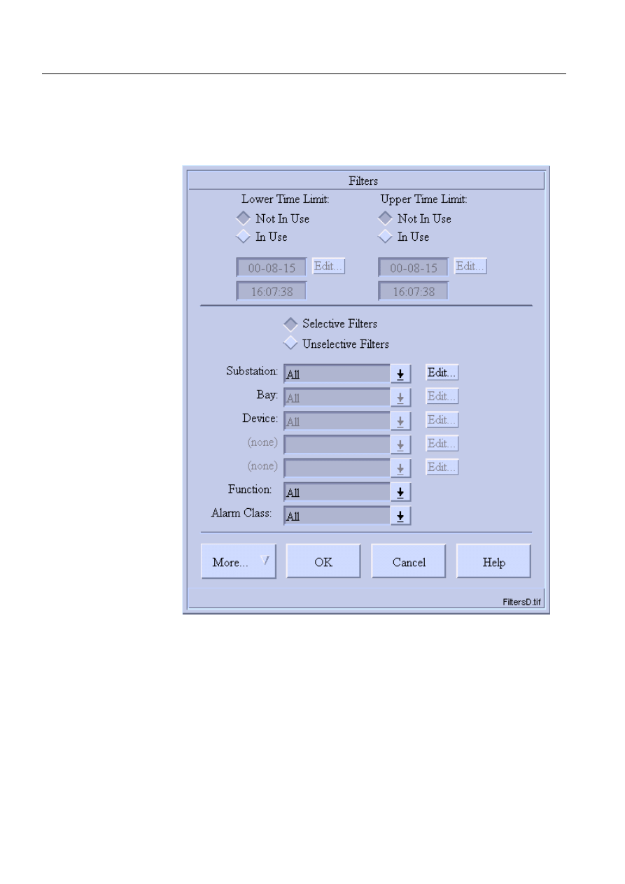
56
1MRS751880-MEN
LIB 500 Configuration Manual
LIB 500
5. Alarm list
Configuration Guide
highlighted. The Add button adds the selected names, and Add All adds all names
from the list on the left to the list on the right. Remove deletes the selected items and
Remove All removes all items from the list on the right. OK applies the station
names to the main dialog, Cancel only closes the dialog and Help opens the help
dialog.
)LJ
7KH)LOWHUVGLDORJ
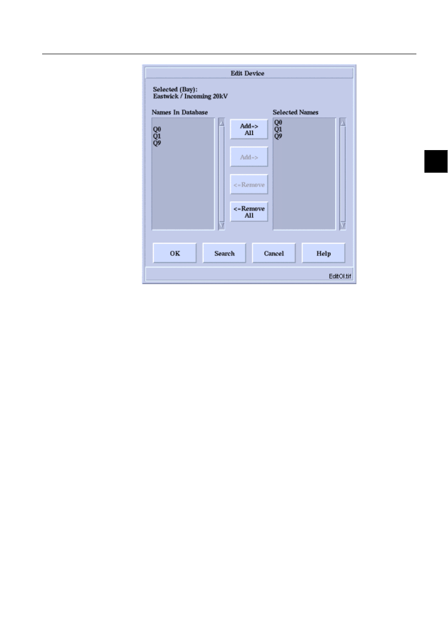
1MRS751880-MEN
LIB 500
57
LIB 500 Configuration Manual
Configuration Guide
5. Alarm list
5
)LJ
7KH(GLW2,GLDORJ
It must be noted that when “all” is selected on any level, all the selections on the
lower levels are reset to “all”, and the Edit buttons on the right side of the lower-level
combo boxes are not available. Furthermore, every time a new object is selected, the
value of the lower-level combo boxes is reset to “all”! This is done to prevent
selection of a non-existing field combination.
5.2.2.
Saving and reading filters
When selecting OK in the Filters dialog, settings and changes will be in use until the
Alarm List is closed. To save the settings and/or changes permanently, click the
button More... and select the option Preconfigurations, after which the Filter
Preconfigurations dialog box appears (see Fig. 5.2.2.-1), and a name has to be typed
for the desired filter configuration. Settings for existing filters can be changed by
first loading the filter using Load command in More… and saving the filter with the
same name.
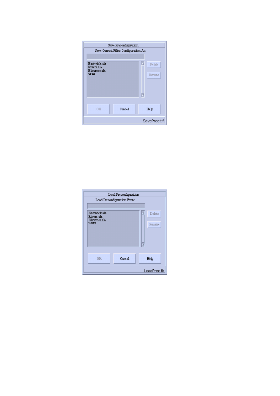
58
1MRS751880-MEN
LIB 500 Configuration Manual
LIB 500
5. Alarm list
Configuration Guide
)LJ
)LOWHU3UHFRQILJXUDWLRQVGLDORJ
After typing a name to the current filter configuration in the field in the upper part
of the dialog, press <Enter> and click OK. The new name will be shown on the list
when entering the dialog the following time. After activating a name on the list (by
clicking it with the mouse), the Delete and Rename buttons will become available.
It is possible to load a preconfigured filter from a file by selecting it from the filter
dialog (see Fig. 5.2.2.-2). Loading dialog is opened from More… menu of filter
dialog.
)LJ
/RDG3UHFRQILJXUDWLRQGLDORJER[
When a filter has been saved or loaded and no changes are made to settings before
pressing OK button is in the filter dialog, the picture header of the Alarm List is
replaced with the filter name.
5.2.2.1.
Making a menu item of a filters reconfiguration
A preconfigured filter, which was given a name in the Filters preconfigurations
dialog (see Fig. 5.2.2.-1), can be added to the Alarm List menu as described in this
section. The menu item is then available in REPORTS/Alarm List/Template x/xxx.
Changing of menu item in template 1 and 2 is performed in the following way:
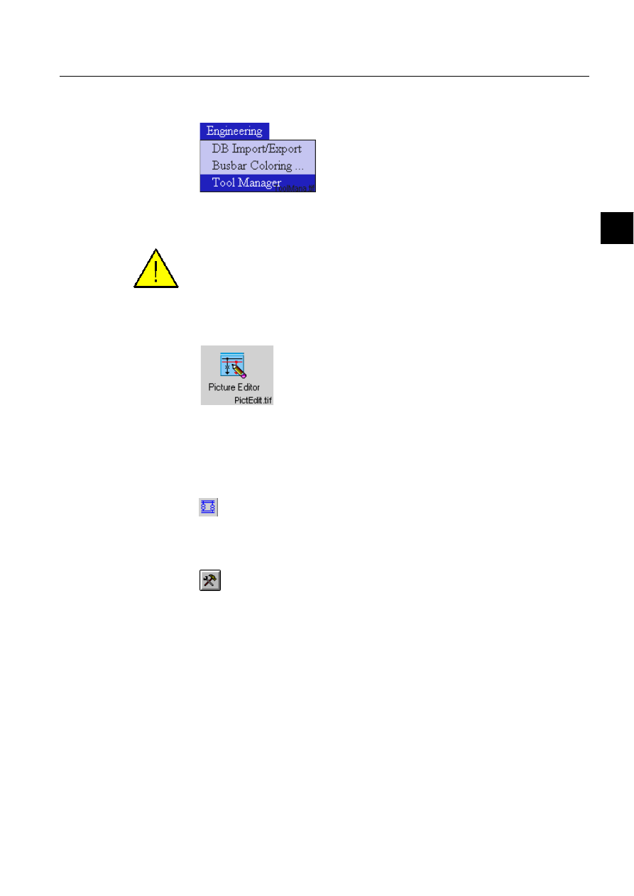
1MRS751880-MEN
LIB 500
59
LIB 500 Configuration Manual
Configuration Guide
5. Alarm list
5
1. Open the Picture Editor by opening the Engineering menu and by selecting the
Tool Manager.
)LJ 6HOHFWLQJWKH0LFUR6&$'$7RRO0DQDJHUIURPWKH(QJLQHHULQJ
PHQX
To be able to access the Tool Manager, the user needs to have the authorization level
2 or higher for authority group Tools.
Start the Picture Editor in the User Interface folder by double-clicking the icon.
)LJ 'RXEOHFOLFNWKH3LFWXUH(GLWRULFRQWRVWDUWLW
2. Open the base picture by selecting it in the File menu either by clicking first
Open and then By File Chooser or By Name. Another possibility is to select the
name of the picture on the list in the File menu.
3. Click the Picture Functions button
4. Select the picture by clicking it with the mouse so that handles appear in the
corners of the picture.
5. Click the Configure Function button
6. After clicking the above-mentioned button, the Standard Configuration Tool
dialog box appears.

60
1MRS751880-MEN
LIB 500 Configuration Manual
LIB 500
5. Alarm list
Configuration Guide
)LJ 6WDQGDUG&RQILJXUDWLRQ7RRO
Select the Tools tab by clicking the tab, select the Menu Configuration tool on the
list, and click the Open button under the list. The Menu Configuration Tool dialog
box appears.
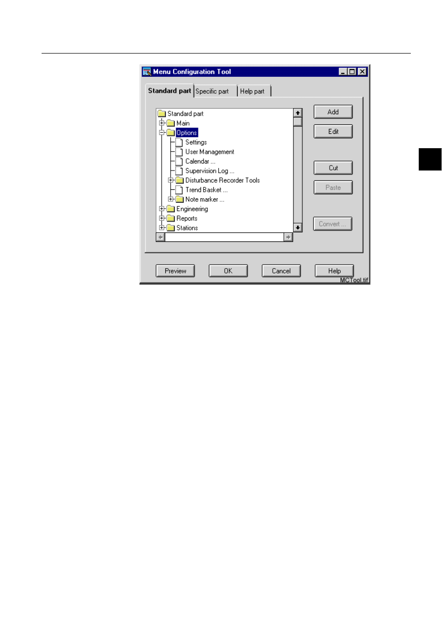
1MRS751880-MEN
LIB 500
61
LIB 500 Configuration Manual
Configuration Guide
5. Alarm list
5
)LJ 0HQX&RQILJXUDWLRQ7RRO
By clicking the + sign in front of the file named Reports (the + sign changes into -
sign after it has been clicked) in the list box, several alternatives become available.
Templates 1 and 2 can be found by clicking the + sign in front of the Alarm List
folder. These templates contain various filters. Select the desired Filter, and press the
Edit button, after which the dialog shown below appears.
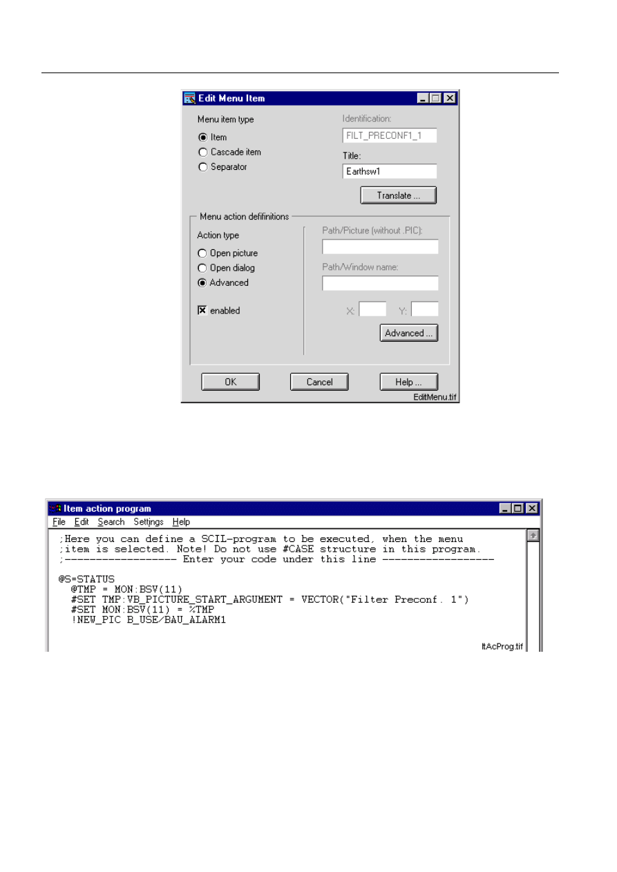
62
1MRS751880-MEN
LIB 500 Configuration Manual
LIB 500
5. Alarm list
Configuration Guide
)LJ (GLW0HQX,WHPGLDORJ
Selecting the Advanced option in the Menu action definition and clicking the
Advanced button opens the Item action program (see Fig. 5.2.2.1.-6). The title of
the filter is shown in the Title: field when the alternative Enabled is selected in the
Menu action definitions.
)LJ ,WHPDFWLRQSURJUDP
The name is shown in brackets on the second row of the code. Change the name
(title) to the name that was given earlier in the Filter preconfiguration dialog and
update the Item action program by selecting the option Update in the File menu.

1MRS751880-MEN
LIB 500
63
LIB 500 Configuration Manual
Configuration Guide
5. Alarm list
5
5.3.
Settings
The ability to change the layout of the Alarm List is based simply on the use of
variables such as the alarm type color numbers, text column positions and string
lengths. These settings can be saved into an application specific text file and read
from there, so that the settings once selected are not lost.
5.3.1.
Color settings
The Alarm List colors are so called M-scope colors. These colors are monitor
specific, i.e. used by all pictures shown in the monitor in question, and they can be
determined with the TOOL Colour Settings picture by changing the RGB
components of the colors. M-scope colors are identified by a number, for example
16 equals to red in
³0´. By giving a new value, each color used in the Alarm List
can be changed. Since these colors can be remixed, they must be selected from a
color palette instead of written color names to avoid confusion.
5.3.2.
Text settings
In the Alarm List settings tools the starting position of each of the five text columns
(date, time, object id, object text and status text) is given in semigraphic characters
(16*20 pixels). A ruler indicating the current column positions and setting limits is
shown.
To avoid excessive string lengths, an upper length limit is determined for each
column. Since four of the five columns consist of attribute values, the maximum
lengths of the attributes provide these limits. It must be noted that as a proportional
font is used, the function between the column lengths and positions is not linear, i.e.
different characters require a different amount of space. As stated before, the length
of the object identification column is determined in the application settings picture.
5.3.3.
Main settings functionality
The two Alarm List Templates have settings dialogs of their own but since the
difference is limited to the amount of alarm types, both of the dialogs can be
described at the same time.
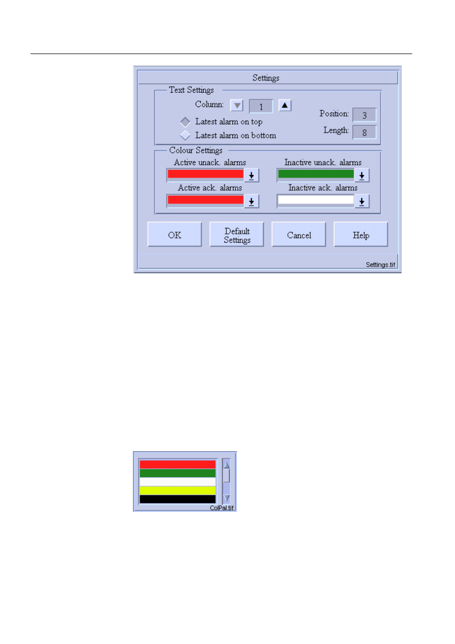
64
1MRS751880-MEN
LIB 500 Configuration Manual
LIB 500
5. Alarm list
Configuration Guide
)LJ
7KH6HWWLQJVGLDORJRIWKH$ODUP/LVW7HPSODWH
When the dialog is opened (see Fig. 5.3.3.-1), active settings are shown.
As it can be seen in the above dialog (see Fig. 5.3.3.-1), the Settings dialog has two
main parts, Text Settings and Color Settings. The former contains length (except for
OI column) and position fields for each of the five Alarm List text columns. There
is also a pair of radio buttons which can be used to determine the drawing order of
the Alarm List, i.e. whether the latest alarm is shown on the top or at the bottom of
the list. The color settings part includes color palettes for each alarm type.
5.3.4.
Color settings
This is where the settings dialogs of the two Templates differ: since inactive
acknowledged alarms are not included in Template 1, its Setting dialog has only
three color palettes while Template 2 has four. With these palettes the user can select
a drawing color for each alarm type from a set of nine M-scope colors. An example
of the color palette can be seen in the following figure.
)LJ
2QHRIWKHFRORUSDOHWWHVLQWKH6HWWLQJVGLDORJ
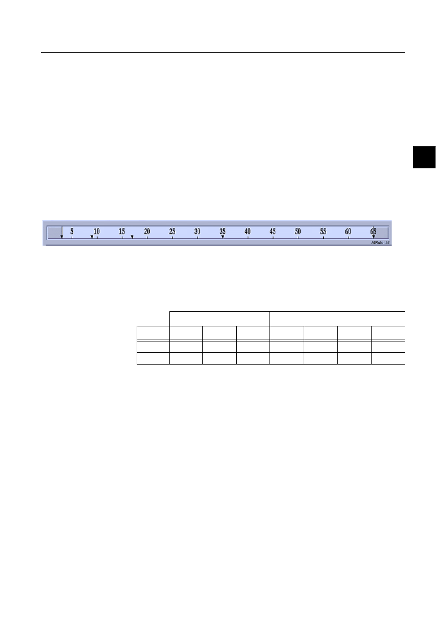
1MRS751880-MEN
LIB 500
65
LIB 500 Configuration Manual
Configuration Guide
5. Alarm list
5
5.3.5.
Text settings
Three different properties of the Alarm List can be modified with the text settings
part of the Settings dialog: the position of each text column, the length of each text
column (except for the OI column) and the order of the alarms on the list. The
column lengths are shown in fields on the upper left part of the dialog. A new value
can be inserted into each field. If it is between 0 and the preset upper limit (given
later) it is accepted, otherwise the old value is returned.
The fields on the upper right part of the dialog contain the position of each column
in semigraphic characters. A new value can also be inserted here. If the value is
valid, i.e. the value is between the preset upper and lower limit (given later) and the
order of the columns from left to right does not change, the new value is accepted,
otherwise the old value is returned. In order to illustrate the positions and limits, the
ruler in the dialog below (see Fig. 5.3.5.-1) is shown when the Settings dialog is
opened. The lighter grey area in the ruler represents the range of limits and the black
triangles represent the current positions.
)LJ
7KH$ODUP/LVWWH[WUXOHU
The following table contains the text settings limits of both Alarm Lists Templates.
These limits are set to prevent the use of irrational settings. Due to a slightly different
layout of the Templates, also the limits are somewhat different.
Table 5.3.5-1
The text settings limits of both Alarm Lists Templates
5.3.6.
Configuring separate columns for each OI field
The feature is taken into use automatically, if the list is using default settings. If the
settings are not visible when opening the list, open Settings dialog and press Default
settings button. This causes the current configuration file to be deleted from the
PICT directory, and as a consequence, the default settings are used.
To configure OI column headers and positions, follow these steps:
1. Take default settings into use: open Settings dialog and press button Default
settings
2. Close the settings dialog by using OK button.
3. Create new configuration file in the PICT directory by opening the Settings
dialog again and closing it with OK button.
4. Open configuration file BAU_ACTSE1.TXT or BAU_ACTSE2.TXT
(depending on the template that is used) with a text editor.
5. Configure column positions in attribute OI_COLUMN_OFFSET of
configuration file. The position units are same as other column positions in
The column. pos limits (sg)
The length limit of column (char.)
Template Lower
Upper
1
2
3
4
4
1
1
63
8
12
-
30
10
2
3
65
8
12
-
30
10

66
1MRS751880-MEN
LIB 500 Configuration Manual
LIB 500
5. Alarm list
Configuration Guide
Settings dialog. All OI fields should be set visible in Backbone Settings picture
before making this to ensure correct appearance.
6. Check that attribute FIVE_OI_COLUMNS is TRUE in configuration file.
7. If other language than English is used, check translation of the language
dependent files of Alarm List. There are some new attributes defined.
8. Define column headers to text vector attribute OI_COLUMN_HEADERS of
LANG
Q/BAU_ALARM1.TXT or BAU_ALARM2.TXT (depending on the
template). Language number
Q depends on used language.
Example configuration file contents:
LIST(COLUMN_POSITIONS=VECTOR(1,7,15,33,63,70),COLUMN_LIMITS=VECTOR(1,63),-
COLUMN_LENGTHS=VECTOR(8,12,30,30,10,1),COLUMN_LENGTH_LIMITS=VECTOR(8,12,-
30,30,10,1),ALARM_COLOUR_NUMBERS=VECTOR(16,32,15,17,14,9,29,30),-
ACTIVE_UNACK_COLOUR=16,ACTIVE_ACK_COLOUR=15,INACTIVE_UNACK_COLOUR=32,-
LATEST_ALARM_ON_TOP=TRUE,OI_COLUMN_OFFSET=(0,5,14,15,16),
FIVE_OI_COLUMNS=TRUE)
5.3.7.
Saving and reading settings
Clicking OK in the Settings dialog saves the settings into the same text file they were
read from.
The settings tool also has a mechanism to return the default settings to the dialog and
thus to the Alarm List. This feature is implemented in order to ensure that the
original values can be returned whenever needed. This function can be utilised in
cases when the settings made by the user are incorrect or need restoration. Please
note that no settings are saved to the default settings files. Cancel and Help button
function as in the filters main dialog.
5.4.
User authorization
When taking the Alarm List into use, make sure that user authorization has been
defined in the User Management picture.
Alarm handling belongs to the LIB 500 user authorization system and it has an
authorization group of its own, ALARM_HANDLING.
Table 5.4.-1 The following table describes the different authorization level in
Templates 1 and 2.
* = only in Template 2
As in other LIB 500 functions, an operator with an insufficient user authorization
level can open all dialogs, but setting the corresponding buttons unavailable
prevents the operations.
Auth level (min.)
Operation
Engineering (2)
Editing station, bay and device lists of the filters
Control (1)
Acknowledgement (single alarm, page*, all*)
Alarm List layout (settings)
View(0)
All other operations

1MRS751880-MEN
LIB 500
67
LIB 500 Configuration Manual
Configuration Guide
5. Alarm list
5
5.5. Additional
information
Pictures used by alarm list
Table 5.5.-1 The pictures located in LIB4/BASE/ALARM/USE directory
Other text files
Table 5.5.-2 The text files located in LIB4/BASE/ALARM/USE directory
Picture
Functionality
BAU_ACKNOA.PIC
Alarm acknowledgement dialog
BAU_ALARM1.PIC
Main picture of alarm list template 1
BAU_ALARM2.PIC
Main picture of alarm list template 2
BAU_ALBUT0.PIC
Button – acknowledge all alarms
BAU_ALBUT1.PIC
Button – open filter dialog
BAU_ALBUT2.PIC
Button – acknowledge page
BAU_ALBUT3.PIC
Button – presentation mode
BAU_ALBUT4.PIC
Button – open settings dialog
BAU_ALBUT5.PIC
Button – go to last alarm
BAU_ALBUT6.PIC
Button – go to previous page
BAU_ALBUT7.PIC
Button – go to next page
BAU_ALBUT8.PIC
Button – open help dialog
BAU_ALBUT9.PIC
Button – reset list
BAU_PRESMA.PIC
Presentation mode selection dialog
BAU_SCRN1A.PIC
Screen window for template 1
BAU_SCRN1B.PIC
Screen window for template 1
BAU_SCRN2A.PIC
Screen window for template 2
BAU_SETTI1.PIC
Settings dialog for template 1
BAU_SETTI2.PIC
Settings dialog for template 2
BAU_SETTIB.PIC
List box
BAU_ALREP.PIR
Presentation file
Text file
Functionality
BAU_TOOL1.MNU
Menu definition file for template 1
BAU_TOOL2.MNU
Menu definition file for template 2
BAU_DEFSE1.TXT
Settings file for template 1
BAU_DEFSE2.TXT
Settings file for template 2
BAU_FILNME.TXT
Configuration file for selected OI filters
PATH4_B5.TXT
Path definition file for alarm list paths

68
1MRS751880-MEN
LIB 500 Configuration Manual
LIB 500
5. Alarm list
Configuration Guide
Help text files
Table 5.5.-3 The help files located in LIB4/BASE/ALARM/LANG0 directory
Language text files
Table 5.5.-4 The text files located in LIB4/BASE/ALARM/LANG0 directory
Help file
Functionality
BAU_ACKNO.HLP
Help file for alarm acknowledgement dialog
BAU_ALARM1.HLP
Help file for main alarm list picture (template 1)
BAU_ALARM2.HLP
Help file for main alarm list picture (template 2)
BAU_PRESM.HLP
Help file for presentation mode selection dialog
BAU_SETTI.HLP
Help file for settings dialog
Text file
Functionality
BAU_ALARM1.TXT
Language dependent texts for main dialog
(template 1)
BAU_ALARM2.TXT
Language dependent texts for main dialog
(template 2)
BAU_SETTI.TXT
Language dependent texts for settings dialog
BAU_TOOL1.TXT
Menu texts for template 1
BAU_TOOL2.TXT
Menu texts for template 2

1MRS751880-MEN
LIB 500
69
LIB 500 Configuration Manual
Configuration Guide
6. Busbar Coloring
6
6. Busbar
Coloring
6.1.
General
6.1.1.
Introduction
There is an increasing demand for dynamically, voltage dependent, colored busbar
lines in single line pictures. So far the engineering task of making lines and picture
elements change their colors, depending on switch states and voltage sources, was
quite time consuming and mostly very project specific, and therefore, not reusable.
MicroSCADA v.8.4.1 introduces this functionality as a part of the standard
MicroLIB PF and the fullgraphic Picture Editor (PE).
A single line diagram picture consists of several standard PF (Switches,
transformers, lines, etc.) which all together form the single line diagram. Each PF
contains its topological information, necessary to build up the electrical network.
Therefore, also the busbar lines, which form the interconnection between 2 PF (e.g.
switches), are implemented as standard PF.
Once the picture editing with the Picture Editor (PE) has been completed, the
Topology Generator (TG) is used to calculate the electrical network with all its
connection points between the PF and to generate the necessary data files for the
runtime coloring algorithm.
Single line diagrams are allowed to spread over several pictures and still belong to
the same electrical topology.
In order to integrate the local substation busbar coloring into the eventually
overlaying geographical coloring covered by MicroTOPOLOGY, a special line
indicator PF is used to export/import coloring information.
Once the data files are generated, the Busbar Coloring program may be started from
a monitor dialog within the single line diagram picture.
6.1.2.
Scope
This document is intended to provide the user with the necessary information to fully
understand the principles of LIB 500 busbar coloring and to be able to engineer, test
and, if necessary, debug such pictures. It is assumed that the reader is familiar with
MicroSCADA and the handling of MicroLIBRARY (LIB 5xx) picture functions.
The details of PF described here deal only with the aspects relevant for busbar
coloring. For basic information on standard PF, please refer to the corresponding
user’s guides (e.g. LIB 500, LIB 510, LIB 530).
6.1.3.
Abbreviations
Table 6.1.3-1
Abbreviations
API
Application Programming Interface. Interface for external programs
to MicroSCADA database
BBONE
Back Bone
CB
Circuit Breaker
CT
Current Transformer
1MRS751880-MEN

70
1MRS751880-MEN
LIB 500 Configuration Manual
LIB 500
6. Busbar Coloring
Configuration Guide
6.2.
Structure
The busbar coloring package supplied by LIB500 includes three visual SCIL
dialogs:
1. The single line editor
2. The topology generator
3. The topology monitor
They are located in the directory path SC/LIB4/BBONE/BB_COL within the
standard subdirectories INST, LANG0 and USE. Since they are an integral part of
LIB500, they do not have to be installed like standard PF. The dialogs are accessed
either via PE or via the pull-down menus in the main menu bar of the base PF.
DS
Disconnector Switch
ES
Earth Switch
HV
High voltage
LIB 500
Application Library 500, the common platform (Base) for ABB
application engineering within MicroSCADA
LIB 510
LIB 520
LIB 530
Function Libraries developed and maintained by local engineering
centres
LN
Logical Name, attribute of process object
MicroLIBRARY
Application Library, previous to LIB 500
MT
MicroTopology
MV
Medium Voltage
OPERA
Network Topology program
MV
Medium voltage
PE
Full graphical Picture Editor
PF
Standard Picture Functions as provided by the different LIB 5xx
packages
PO
Process object (of MicroSCADA database)
SCT
Standard Configuration Tool
SIT
Standard Installation Tool
TG
Topology Generator
TM
Topology Monitor
VS
Visual SCIL
VT
Voltage Transformer

1MRS751880-MEN
LIB 500
71
LIB 500 Configuration Manual
Configuration Guide
6. Busbar Coloring
6
6.2.1.
Visual SCIL Dialogs
Table 6.2.1-1
Visual SCIL Dialogs
6.2.2.
Language Dependant Dialog Texts
All texts shown in the dialogs are part of the corresponding visual SCIL dialogs.
6.2.3.
Text Files
The topology generator dialog uses the following text files (to be found in SC/LIB4/
BBONE/BB_COL/USE) as private methods for precalculation of connection and
parameter lists needed by the busbar coloring runtime program and the topology
program:
Table 6.2.3-1
Text files used by the topology generator dialog as private
methods for precalculation of connection and parameter lists.
7KHVHWH[WILOHVPD\QRWEHFKDQJHG
Furthermore, the following text files are used, which contain the data needed to
handle the known PF with their current functionality are used. The idea is that if a
new PF is introduced or the functionality of an already existing PF is changed, a
parameter file and a template file should be made for the PF.
VS dialog
Functionality
BCI_SLE.VSO
Single line editor, used within PE to draw lines
BCI_MON.VSO
Busbar coloring monitor, starting, stopping and monitoring of
runtime program Topcal.exe
BCI_TG.VSO
Topology generator, used to calculate and generate various data
files
Text file
Functionality
bcu_tgarg.txt
Initialization of arguments
bcu_tgout.txt
Preparation of output variable from each module
bcu_tgpar.txt
For each PF the process objects needed in Topology busbar
coloring are checked and the information is saved in a file
bcu_tgtop.txt
For each PF determines type and status of the PF in the sense of
Topology busbar coloring and the information is saved in a file
bcu_tgpfc.txt
For each PF finds its external connections, e.g. to other picture
functions and the information is saved in a file
Bcu_tgtoc.txt
For each PF a template is used describing the internal
connections, e.g. within the PF itself. This information is
combined with information about external connections of the PF
(described by bcu_tgpfc.txt), and saved in a file
Bcu_tgmto.txt
Calculation of MicroTOPOLOGY object parameter file

72
1MRS751880-MEN
LIB 500 Configuration Manual
LIB 500
6. Busbar Coloring
Configuration Guide
Table 6.2.3-2
The text files that contain the data needed to handle the
known PF with their current functionality
The topology generator accesses the parameter and template files during generation
of the topology files, which are located in the directory SC/APL/apl_name/PICT/-
TOPOLOGY.
Table 6.2.3-3
The parameter and template files that are accessed by the
topology generator during generation of the topology files.
6.2.4.
External Programs
Busbar coloring uses 2 external C-programs communicating through the
MicroSCADA API. Both reside in the SC/PROG/EXEC directory
Table 6.2.4-1
External Programs
Def_parameter.txt
Mapping PF attributes to attributes of a list variable, which used in
the rest of the calculation
Def_template.par
Containing a template of process objects needed in Topology
busbar coloring for each PF. This file is called from bcu_tgpar.txt.
Def_template.top
Containing a template of type and status of each PF in sense of
Topology busbar coloring. This file is called from bcu_tgtop.txt.
Def_template.toc
Containing a template of internal connections for each PF. This file
is called from bcu_tgtoc.txt.
Cpi_hvt2old.txt
Containing templates needed for 2 winding transformer PF
Cpi_hvt3old.txt
Containing templates needed for 3 winding transformer PF
Text file
Functionality
Topology_name
Object file used by run time program
Topology_name.TXT
List containing attributes of each PF which are relevant to
topology busbar coloring
Topology_name.PFC
List of external connections, e.g. between picture functions
Topology_name.PAR
List of process objects of each PF which are relevant to
topology busbar coloring, used by runtime program
Topology_name.TOP
List of type and status of each PF in sense of topology busbar
coloring
Topology_name.TOC
List of internal and external connections of each PF
Topology_name.MTC
MicroTOPOLOGY connection list file
Topology_name.MTO
MicroTOPOLOGY object file
Topology_name.LOG
Error and warning messages occurring during generation of
topology files and runtime
TOPO_DIR.TXT
List of already generated topologies, used for selection at
topology generation by BCI_TG.VSO
External programs
Functionality
Con2top.exe
Part of the precalculation and data generation. Called by VS
dialog BCI_TG.VSO
Topcal.exe
Runtime algorithm which calculates new colors for all PO at
occurrence of change events.

1MRS751880-MEN
LIB 500
73
LIB 500 Configuration Manual
Configuration Guide
6. Busbar Coloring
6
6.2.5.
Objects
During topology generation with the topology generator dialog, the following
process objects and command procedure will be generated:
Table 6.2.5-1
Process objects and command procedure
6.2.6.
Coloring Scheme
In order to keep control over the colors (representing the different voltage states)
spreading along the lines of the single line diagram, some rules and conventions had
to be defined. Basically 4 main voltage states are distinguished:
Table 6.2.6-1
Main voltage levels
Since there may be several active voltage sources within a station acting on the same
busbar, a way of defining coloring priorities is necessary. This is done by means of
the color scope and color number. The 4 standard voltage states described above are
monitor colors and have fixed color numbers which can be found in the ”M” scope
color definitions (see MicroSCADA color definition tool):
Table 6.2.6-2
“M” scope color definitions
Additionally to these 4 predefined ”M” scope colors, a range of user definable colors
from the ”U” scope may be used to distinguish and set the priorities of multiple
Process objects
Functionality
topology_name:P40
Error code generated during runtime
topology_name:P43
Object used for automatic start up
topology_name:P44
No. of errors reported from Con2top.exe during precalculation
topology_name:P45
External program no. (AEP) of Topcal.exe. Used for starting and
stopping the task.
topology_name:P60
Running state of Topcal.exe
topology_name:P61
Initiates runtime calculation of Topcal.exe
BCU_TPSTRT:C
Starts up automatically the topology (see Section 6.5.2)
Passive
Line is disconnected from voltage source and not grounded either
Grounded
Line is disconnected from voltage source and grounded
Unknown
Line has unknown voltage state. E.g. line is connected to active voltage
source and is grounded at the same time
Active
Line is connected to active voltage source. The active potential is either
supplied by a generator PF, an infeeding line (Line indicator PF) or the
secondary side of a transformer PF acting as a voltage source.
”M” scope color no.
Meaning
33
Passive. No voltage potential is present
34
Grounded. Line is grounded
35
Feeder voltage. For internal use only
36
Active. Voltage potential is present
37
Unknown voltage situation

74
1MRS751880-MEN
LIB 500 Configuration Manual
LIB 500
6. Busbar Coloring
Configuration Guide
active voltage sources. The following ”U” scope color number range is available for
DFWLYH voltage states:
1..32, 38..50
The color numbers of the other voltage states
PD\QRW be changed. If another color
is needed for those states, the color itself should be changed by means of the color
tool.
3ULRULW\UXOHV
• ”U” scope color numbers have higher priority than the standard ”M” scope active
color number 36 of ”M” scope.
• If ”grounded” color meets ”active” color, the whole line gets the ”unknown state”
color
• Within the ”U” scope color number range: The higher the number, the higher the
priority of the color.
• If two active colors meet in the single line, the color with the higher priority will
be spread.
6.3.
Installation and Configuration
6.3.1.
Installation and Configuration of Standard Picture Functions
The first step consists of installing the base PF, the station PF and the necessary bay
PF. After that the installation of the single line elements may start. From busbar
coloring point of view it is not relevant, whether the switching device PF or the line
PF is installed first. There is, however, a practical reason to start by first installing
the switching devices, transformers, etc, and then add the line PF. The single line
editor provides the line PF with a ”snap-on” functionality, allowing the line to snap
on the connection points of the other PF if the line is drawn close enough to them.
Since only the line PF are provided with this functionality, they should possibly be
drawn at the end to ensure, that the connection points of two adjacent PF really do
match. If they do not match (even if there is only 1 pixel difference) the connection
will not be recognized and therefore produce wrong data files and error messages
(see Section 6.6).
Standard PF are installed by means of the MLIB Standard Installation Tool (SIT)
and afterwards configured with the MLIB Standard Configuration Tool (SCT). In
this chapter only busbar relevant parameters are discussed.
6.3.1.1.
Switching Devices
No special configuration is needed for CBs, isolators, etc.
However, because busbar coloring has to support picture functions of different
function libraries like LIB510 and LIB530 a remark is needed concerning CB with
Truck picture function.
CB with Truck in LIB530 consists of one picture function, acting like two trucks
with a CB in between, while in LIB510 it can consist of two or three Switching
Device picture functions with or without line segments in between (see Figure 1). In
busbar coloring the CB with Truck PF in LIB530 has the topology type
CB_WITH_TRUCK which means that the same logical name (P_OBJECT_LN) is
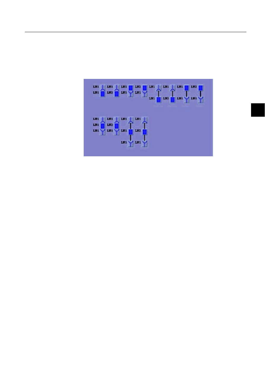
1MRS751880-MEN
LIB 500
75
LIB 500 Configuration Manual
Configuration Guide
6. Busbar Coloring
6
used to describe the whole picture function. For CB with Truck in LIB510 the Truck
PF(s) and the CB PF can have the same or different logical names
(P_OBJECT_LN), therefore in busbar coloring each Truck and CB is treated as a
separate PF, which can either be connected directly or through line segments.
No configurable PF attribute exists for CB with Truck in LIB530 or Switching
Device PF in LIB510.
)LJ 3RVVLEOH&%ZLWK7UXFNFRQILJXUDWLRQVLQ/,%VXSSRUWHGE\
EXVEDUFRORULQJ
6.3.1.2.
Transformers
Depending on the coloring requirement, transformers may be utilised and
configured in different ways.
1. No change of color shall happen between primary and secondary side of the
transformer. The infeeding source spreads it’s color across the transformer
2. A change in voltage state (see Section 6.2.6) of a line segment connected to a
transformer winding will propagate through the transformer. If the line segment
connected to the winding (primary, secondary or tertiary) gets the voltage state
”PASSIVE”, “GROUNDED”, “UNKNOWN” or “ACTIVE”, the other
windings get the voltage state (and color) of ”PASSIVE”, “GROUNDED”,
“UNKNOWN” or “ACTIVE” state respectively. The voltage state (and color) of
these windings are then propagated to the line segments connected to them.
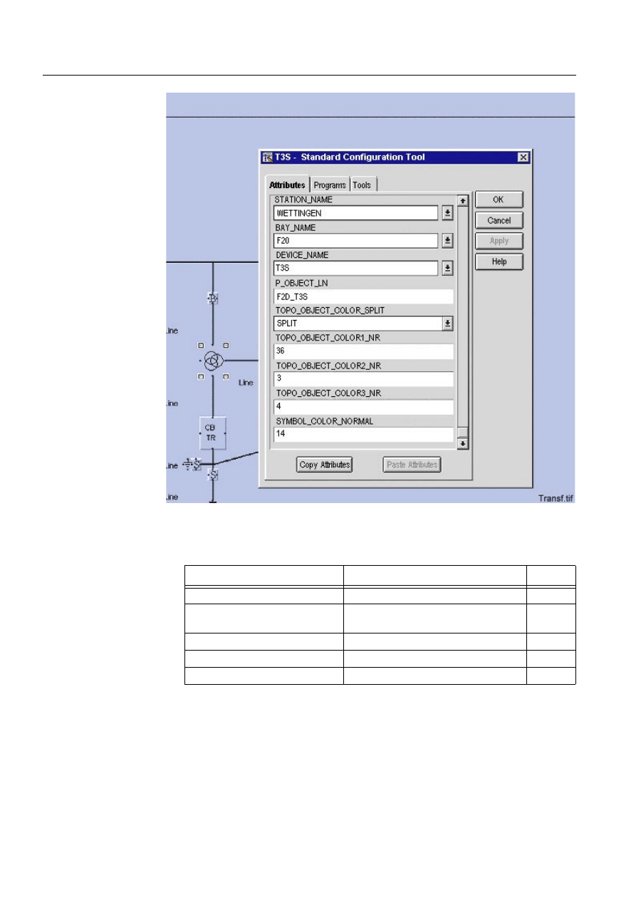
76
1MRS751880-MEN
LIB 500 Configuration Manual
LIB 500
6. Busbar Coloring
Configuration Guide
)LJ 7UDQVIRUPHU
Table 6.3.1.2-1
The transformer PF has following busbar coloring attributes,
which can be configured.
Configurable Attribute
Meaning
Default
P_OBJECT_LN
Logical name of database process obj.
-
TOPO_OBJECT_COLOR_
SPLIT
Active color for each winding
”NONE”
TOPO_OBJECT_COLOR1_LN
Color no. of primary winding
36
TOPO_OBJECT_COLOR2_LN
Color no. of secondary winding
36
TOPO_OBJECT_COLOR3_LN
Color no. of tertiary winding
36

1MRS751880-MEN
LIB 500
77
LIB 500 Configuration Manual
Configuration Guide
6. Busbar Coloring
6
For more information on color numbers, please see Section 6.2.6.
Table 6.3.1.2-2
The following busbar coloring specific process objects are
needed within the transformer PF:
For more information on color numbers see Section 6.2.6
P_OBJECT_LN
The logical name of the database process objects
used by this PF. The maximum length of the text is 10
characters.
TOPO_OBJECT_COLOR_SPLIT
Determines if secondary and tertiary windings should
propagate their color to the line segments connected
to them, or the color of the line segment connected to
primary winding should propagate through the
transformer.
TOPO_OBJECT_COLOR1_NR
Active color no. of primary winding, in case where the
primary side shall act as a potential source
TOPO_OBJECT_COLOR2_NR
Active color no. of secondary winding, in case where
the secondary side shall act as a potential source
TOPO_OBJECT_COLOR3_NR
Active color no. of tertiary winding (3 winding
transformer only), in case where the tertiary side shall
act as a potential source.
Process Object
Meaning
P_OBJECT_LN
Logical name of database process obj. -
TOPO_OBJECT_COLOR_SPLIT
Active color for each winding
”NONE”
TOPO_OBJECT_COLOR1_LN
Color no. of primary winding
36
TOPO_OBJECT_COLOR2_LN
Color no. of secondary winding
36
TOPO_OBJECT_COLOR3_LN
Color no. of tertiary winding
36
P_OBJECT_LN
The logical name of the database process objects
used by this PF. The maximum length of the text is
10 characters.
TOPO_OBJECT_COLOR_SPLIT
Determines if secondary and tertiary windings
should propagate their color to the line segments
connected to them, or the color of the line
segment connected to primary winding should
propagate through the transformer.
TOPO_OBJECT_COLOR1_NR
Active color no. of primary winding, in case where
the primary side shall act as a potential source
TOPO_OBJECT_COLOR2_NR
Active color no. of secondary winding, in case
where the secondary side shall act as a potential
source
TOPO_OBJECT_COLOR3_NR
Active color no. of tertiary winding (3 winding
transformer only), in case where the tertiary side
shall act as a potential source.
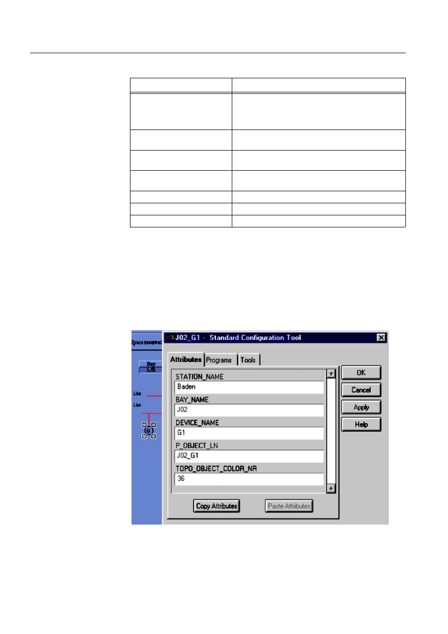
78
1MRS751880-MEN
LIB 500 Configuration Manual
LIB 500
6. Busbar Coloring
Configuration Guide
Table 6.3.1.2-3
The following busbar coloring specific process objects are
needed within the transformer PF:
6.3.1.3.
Voltage Sources and Terminals
Generator
The generator PF acts as a continuous voltage source. It spreads its color on the
single line as far as the line is not interrupted by a switch. If two or more voltage
sources (Generator PF or line indicator PF) are present and a connection between
them is made, the color of the PF with the higher priority prevails over the others.
See also Section 6.2.6.
)LJ *HQHUDWRU
Process Object
Meaning
P_OBJECT_LN:P240 to
P_OBJECT_LN:P244, and
P_OBJECT_LN:P253 to
P_OBJECT_LN:P255
Fictive switches, internal use only
P_OBJECT_LN:P246
Fictive line segment connected to the first winding,
internal use only
P_OBJECT_LN:P247
Fictive line segment connected to the second winding,
internal use only
P_OBJECT_LN:P248
Fictive line segment connected to the third
winding, internal use only
P_OBJECT_LN:P250
Color no. of first winding
P_OBJECT_LN:P251
Color no. of second winding
P_OBJECT_LN:P252
Color no. of third winding
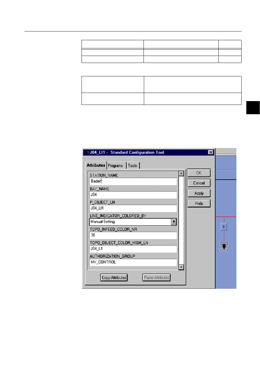
1MRS751880-MEN
LIB 500
79
LIB 500 Configuration Manual
Configuration Guide
6. Busbar Coloring
6
Table 6.3.1.3-1
Configurable Attributes
Line Indicator
In addition to the generator, infeeding lines are possible voltage sources into a
substation. The direction of the voltage flow may, however, change. This requires a
separate PF handling this in-/outgoing power flow, the Line indicator PF. This PF
may be controlled by three different mechanisms:
)LJ /LQHLQGLFDWRU
1. If MicroTOPOLOGY is used in the same environment, then this PF allows to
make the connection to it. MT will then define the power flow direction and
write it appropriately into the PO of the PF
Configurable Attribute
Meaning
Default
P_OBJECT_LN
Logical name of database process obj.
-
TOPO_OBJECT_COLOR_NR
Active color no. of generator
36
P_OBJECT_LN
The logical name of the database process objects used
by this PF. The maximum length of the text is 10
characters.
TOPO_OBJECT_COLOR_NR
Active color no. that will be spread on the single line
diagram by the generator PF.
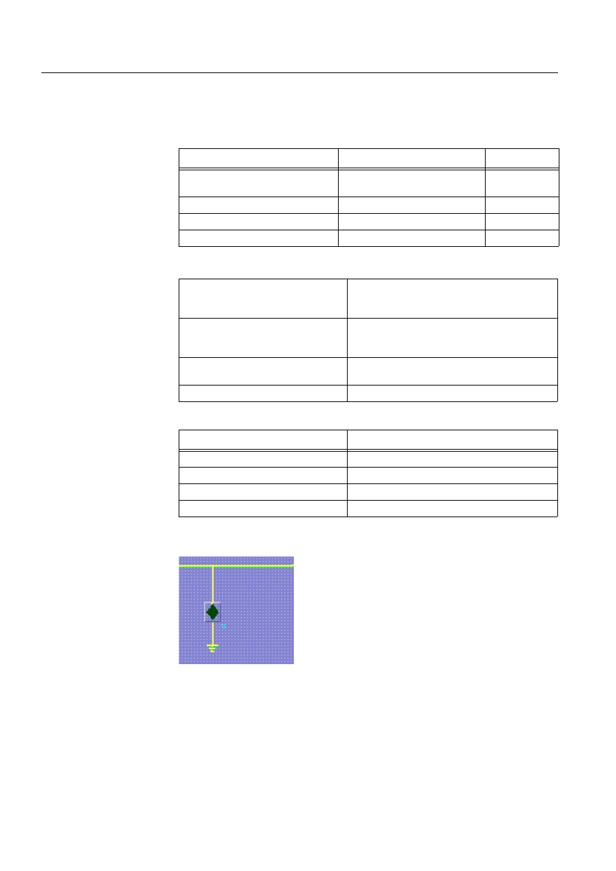
80
1MRS751880-MEN
LIB 500 Configuration Manual
LIB 500
6. Busbar Coloring
Configuration Guide
2. Busbar coloring manages the PF. An external signal from the process must then
be mapped to the right PO to inform the PF about the power flow direction.
3. The direction of the power flow is set manually, via a PO
Table 6.3.1.3-2
Configurable Attributes
Table 6.3.1.3-3
Process Objects
Ground Terminal
)LJ *URXQG7HUPLQDO
The ground terminal PF has no configurable attributes at all. The color number for
grounded state is 34 (”M” scope) and
PD\QRW be changed! If the color itself, yellow
by default, has to be changed to suit the project needs, then the color must be mixed
with the help of the color tool.
Configurable Attribute
Meaning
Default
P_OBJECT_LN
Logical name of database process
obj.
-
LINE_INDICATOR_COLORED_BY
Voltage(color) source
Busbar coloring
TOPO_INFEED_COLOR_NR
Active color no. of infeeding line
36
TOPO_OBJECT_COLOR_HIGH_LN LN of connected line segment PF
-
P_OBJECT_LN
The logical name of the database process objects
used by this PF. The maximum length of the text is
10 characters.
LINE_INDICATOR_COLORED_BY
Determines whether the PF will be controlled by :
”MicroTOPOLOGY”, ”Busbar coloring” or by
”Manual setting”.
TOPO_INFEED_COLOR_NR
Active color no. that will be spread on the single
line diagram by the generator PF.
TOPO_OBJECT_COLOR_HIGH_LN
LN of connected line segment PF
Process Object
Meaning
P_OBJECT_LN:P10
MicroTOPOLOGY pen no.
P_OBJECT_LN:P253
virtual switch, connects external source
P_OBJECT_LN:P254
Ground color no., if externally grounded
P_OBJECT_LN:P255
Color no. of Infeeding voltage source
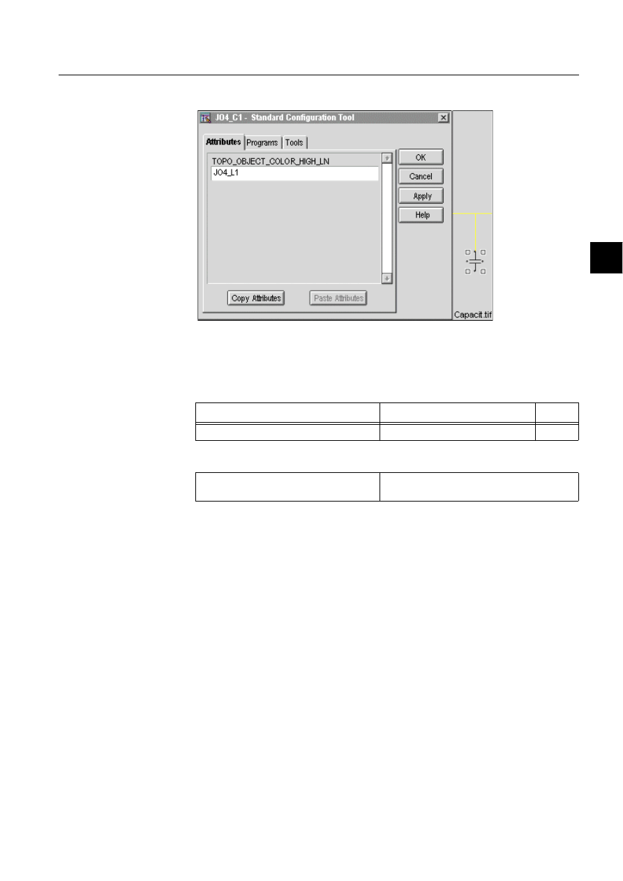
1MRS751880-MEN
LIB 500
81
LIB 500 Configuration Manual
Configuration Guide
6. Busbar Coloring
6
Motor, Capacitor, Reactance
)LJ &DSDFLWRU
These 3 PFs are passive elements with no own PO. They receive their dynamic color
information from the connected line PF.
Table 6.3.1.3-4
Configurable Attributes
6.3.2.
Installation and Configuration of Line Picture Functions
6.3.2.1.
Installation
The Line PF is also installed by the SIT. After installation the PF consists only of a
label (see Figure 6.3.2.2.-1) which may basically be placed anywhere in the picture,
but should preferably be moved to the area, where the line elements belonging to it
are likely to be drawn with the Single Line Editor (SLE) afterwards.
Configurable Attribute
Meaning
Default
TOPO_OBJECT_COLOR_HIGH_LN
LN of connected line segment PF
-
TOPO_OBJECT_COLOR_HIGH_LN
LN of connected line segment PF which will
pass its color to the PF
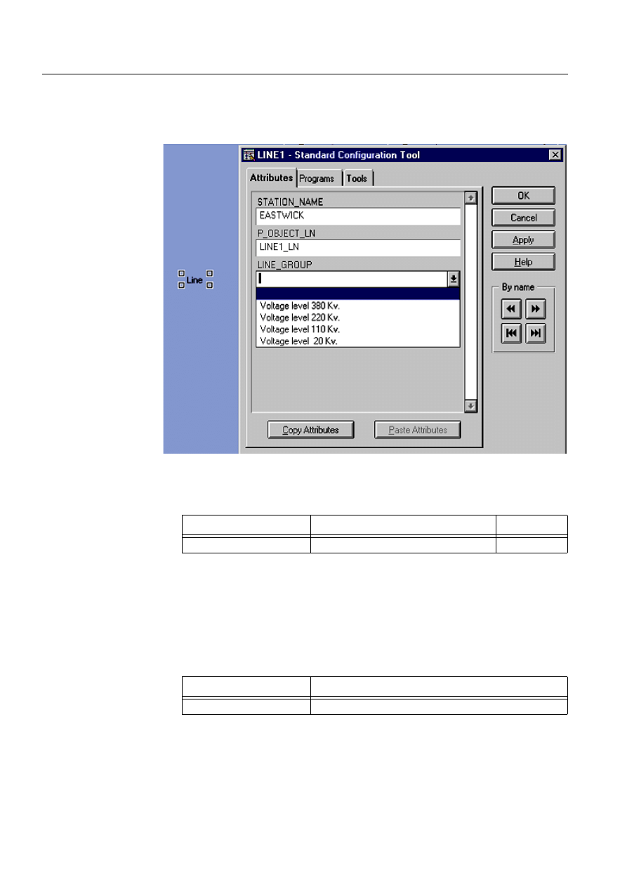
82
1MRS751880-MEN
LIB 500 Configuration Manual
LIB 500
6. Busbar Coloring
Configuration Guide
6.3.2.2.
Configuration
The line PF has three attributes, from which two can be configured with the SCT
concerning busbar coloring.
)LJ /LQH&RQILJXUDWLRQ
Table 6.3.2.2-1
The line PF attributes relevant to busbar coloring, which can
be configured
P_OBJECT_LN
The logical name of the database process objects used by
this PF. The maximum length of the text is 10 characters.
LINE_GROUP
The name of user configured line group. A
LINE_GROUP is a group of lines, which have common
busbar coloring attributes.
Table 6.3.2.2-2
Busbar coloring specific process objects that are needed
within the LIne PF
The LINE_GROUP attribute gives the user possibility to decide how line segments
should be shown (color and shape) in different voltage states. The voltage state of a
line segment is calculated by busbar coloring algorithms. The default value for
Configurable Attribute
Meaning
Default
P_OBJECT_LN
Logical name of database process obj.
-
Process Object
Meaning
P_OBJECT_LN:P254
Will contain the calculated number for the voltage state

1MRS751880-MEN
LIB 500
83
LIB 500 Configuration Manual
Configuration Guide
6. Busbar Coloring
6
LINE_GROUP attribute is empty (see Figure 6.3.2.2.-1), which means that default
coloring scheme for busbar coloring (see Section 6.2.6) will be used. The user must
decide how many line groups that will be needed in a project and configure the line
group names and numbers accordingly in the configuration file
(APL\apl_name\APLMOD4\inst\BCI_PROJECT.TXT). For instance lines can be
assigned to different line groups according to the voltage level of the line as shown
in Figure 6. In this case during PF installation the proper voltage level is chosen for
the LINE_GROUP attribute. For each line group the user can configure the line
attributes in each voltage state in the configuration file (APL\apl_name\APLMOD4
\inst\BCI_PROJECT.TXT).
The configuration file BCI_PROJECT.TXT, contains the project specific
configuration of line attributes for each line group. This file has two parts first part
where the line attributes are assigned to default values, and second part where two
variables are defined for Line group definitions (@Line_gr_def) and Line group
attributes (@Line_group). @Line_gr_def defines line group numbers, used
internally, and line group names, shown in LINE_GROUP attribute of Line PF.
@Line_group is the second variable of BCI_PROJECT.TXT, which is a vector
containing list variables with all attributes of Graphics Context (GC). @Line_group
is used in BCI_BBCINI.TXT. By changing the values assigned to attributes in
@Line_group, the behaviour of the line segments in that line group concerning
busbar coloring is changed.
No matter if the LINE_GROUP attribute has been configured or not, the line
segments are drawn using SLE, which is described in the next section.
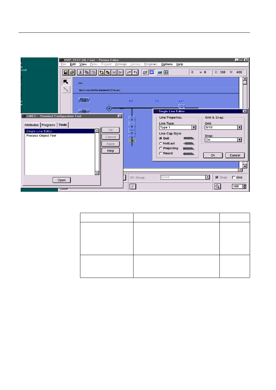
84
1MRS751880-MEN
LIB 500 Configuration Manual
LIB 500
6. Busbar Coloring
Configuration Guide
6.3.2.3.
Drawing Lines with Single Line Editor
The Single Line Editor itself is started from the Tools menu of the SCT.
)LJ 6LQJOH/LQH(GLWRU
Table 6.3.2.3-1
Configurable attributes
Configurable Attribute
Meaning / Values
Default
Line Type
Defines the line width. Each line element
within a line PF may have another line style.
Type 1 => 1 Pixel
Type 2 => 2 Pixel
Type 3 => 4 Pixel
Type 4 => 8 Pixel
Type 1
Line Cap Style
Shape of the line element endings. This must
be considered when horizontal and vertical
lines of different line widths join together. In
most cases the default value suits fine.
“Butt”
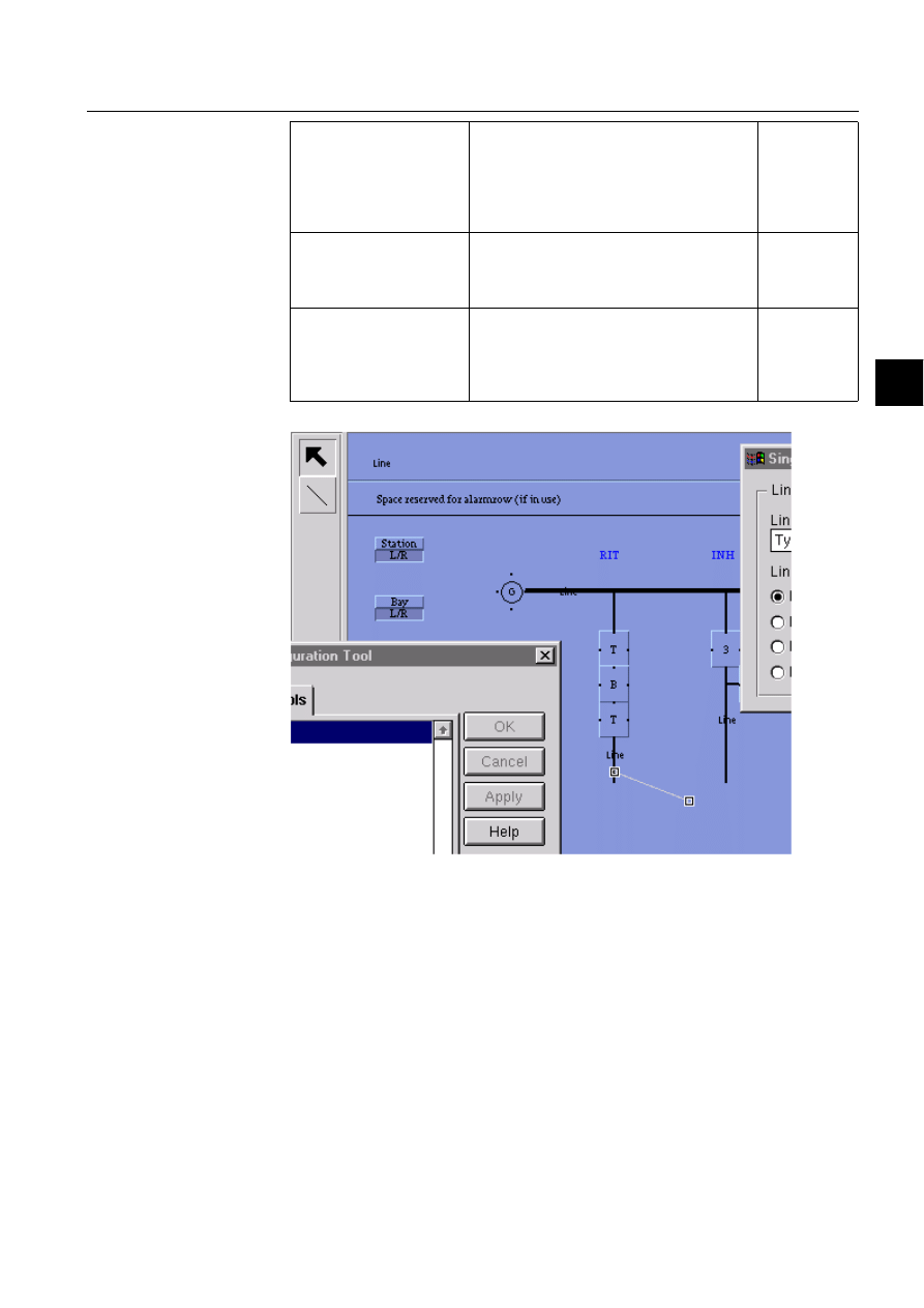
1MRS751880-MEN
LIB 500
85
LIB 500 Configuration Manual
Configuration Guide
6. Busbar Coloring
6
)LJ 'UDZLQJOLQHVZLWKWKH6/(
The line elements of the selected line PF are now drawn by selecting the line button
on the upper left side of the PE. The line elements may be drawn anywhere, in all
directions. They must only be graphically connected together. They will all get the
same color because they belong to the same line PF. Therefore, a line is used for all
the line segments, as far as they are on the same voltage state without any switching
device in between. There are however, also other meaningful applications, such as
the one described in Section 6.4.4.
In order to edit an existing line element, click on the line element. Two squares
highlight the endings. Click on the line end, which you want to move and keep the
mouse button down. After a short time the square around the ending becomes larger
and you may move the ending of the line to the desired location. Then release the
Grid Spacing
Defines the width of the grid cells. When PF
are moved, they always move stepwise
depending on the grid spacing.
8x10 (Half a character)
16x20 (One character)
32x40 (Two characters)
8x10
Grid
Switch to make the grid visible/invisible. A
visible grid may slow down considerably the
drawing performance. Usually it should be
turned off.
Marked (grid
visible)
Snap
Snap functionality of line editor. When lines
are drawn close enough to a connection point
of some other PF (e.g. Breaker) the line will
snap on to the nearest connection point of the
PF.
Marked (snap
enabled)

86
1MRS751880-MEN
LIB 500 Configuration Manual
LIB 500
6. Busbar Coloring
Configuration Guide
mouse button. To move the whole line element, click on the line element and drag
it to the desired location.
When the line PF label is moved, the line PF with all its line elements is moved.
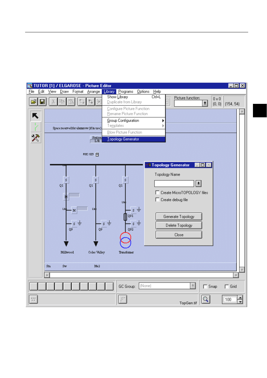
1MRS751880-MEN
LIB 500
87
LIB 500 Configuration Manual
Configuration Guide
6. Busbar Coloring
6
6.4.
Generating Topology
6.4.1.
Topology Generator
Once the picture is drawn and all picture functions have been installed and
configured, the picture must be saved and reloaded again. Then PF editing is
chosen and afterwards the topology generator may be started from the Library
menu.
)LJ
7RSRORJ\*HQHUDWRU

88
1MRS751880-MEN
LIB 500 Configuration Manual
LIB 500
6. Busbar Coloring
Configuration Guide
Table 6.4.1-1
Configurable attributes
Pressing the button “Create Topology” will create the topology files and process
objects needed, if the chosen
WRSRORJ\BQDPHis valid. In order to delete a topology
created with TG properly, the “Delete Topology” button should be used.
6.4.2.
Directory Structure
As described in Section 6.2.3, the TG creates a set of files describing the topology.
They will all be copied into the directory "SC/APL/
DSOBQDPH/PICT/TOPOLOGY".
If the directory does not yet exist, it will be created. If everything works out fine and
no errors are produced during generation, no error message file
"
WRSRORJ\BQDPH.log" will be created. If, however, errors were produced, it might be
necessary to interpret some of these files. See Section 6.6
6.4.3.
Single Line Diagrams Covering More Than One Picture
Large single line diagrams may extend beyond more than one picture and therefore,
also the coloring of multiple pictures using the same topology is supported. In order
to link several pictures together, a few rules must be observed.
6.4.4.
Static Coloring vs. Dynamic Coloring
So far the assumption was made that full dynamic coloring was needed. Of course,
lots of projects do not need this functionality at all, rising the question when is it
appropriate to draw the lines with the Picture Editor only (normal background) and
when it might be more advantageous to use the SLE. Generally speaking, if colored
lines are not the issue at all, all lines should be drawn as normal background lines
with the PE, and therefore, avoiding to blow up (and slow down the picture
performance) the picture unnecessarily with additional PF. If, however, coloring
may become an issue someday, even if at the beginning the line colors shall remain
static, then the approach with the SLE is the better alternative.
Configurable Attribute Meaning
Topology Name
Symbolic name which will then be used to tie together all data
belonging to the same electrical topology. If several pictures
should be tied together, then the same name must be used in all
pictures to generate the data files. The topology name is limited to
8 characters and must be in the range A... Z and 0... 9.
MicroTOPOLOGY files
Option to generate 2 additional data files, which may be imported
by MicroTOPOLOGY to get a description of the substation
configuration.
Debugging information
Option to generate a debug file ("topology_name.TXT"), which
contains all information about picture functions used in generating
the topology files.
1.
When generating the topology with the TG for each picture, the same topology
name must be used
2.
If the color stretches from one picture to another (e.g. a busbar line continuing
through several pictures), the same PO (same P_OBJECT_LN) should be used in
all the pictures.
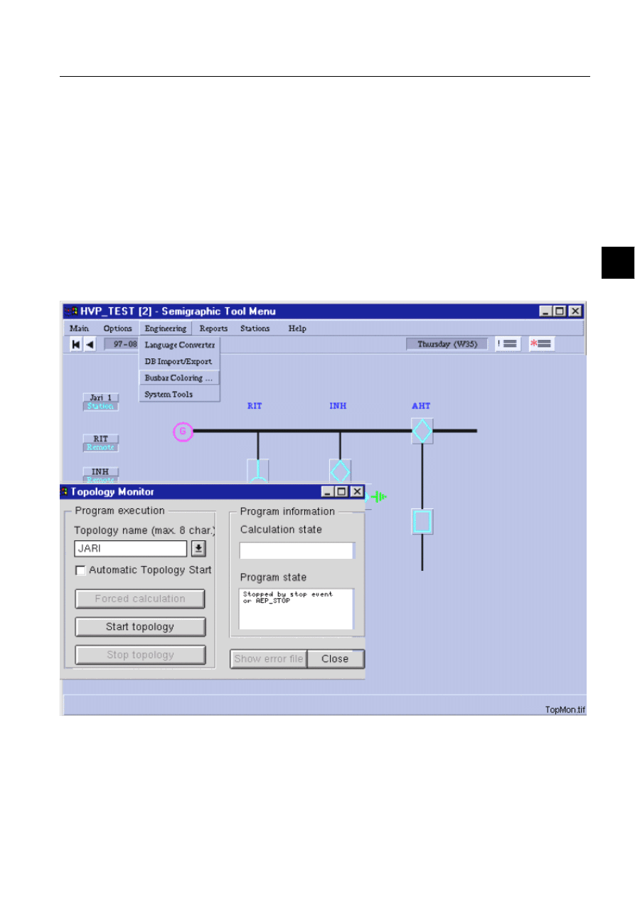
1MRS751880-MEN
LIB 500
89
LIB 500 Configuration Manual
Configuration Guide
6. Busbar Coloring
6
In case two static colors are requested, one for the high voltage part of the single line,
the other for the lower voltage side. This could be done either by PE only or by
defining two line PF. Each PF would then cover all line segments on one voltage
part. By doing it that way you are able to change the color for a whole voltage state
just by changing one color value in the PO of the corresponding line PF.
6.5.
Starting and Stopping Busbar Coloring
6.5.1.
Topology Monitor
Once the busbar coloring files are generated, you may exit the PE and start the
picture. There is no coloring of the lines at the first start-up. The coloring algorithm
must first be initialised and started with the specific topology data. This task is
achieved with the topology monitor (TM), a VS dialog opened from the main menu
bar in the engineering menu item.
)LJ
7RSRORJ\0RQLWRU
First the name of the topology must be selected to specify the data set to be loaded.
Afterwards the runtime calculation program may be started. In the status field on the
right side of the TM the actual state of the calculating program is displayed.
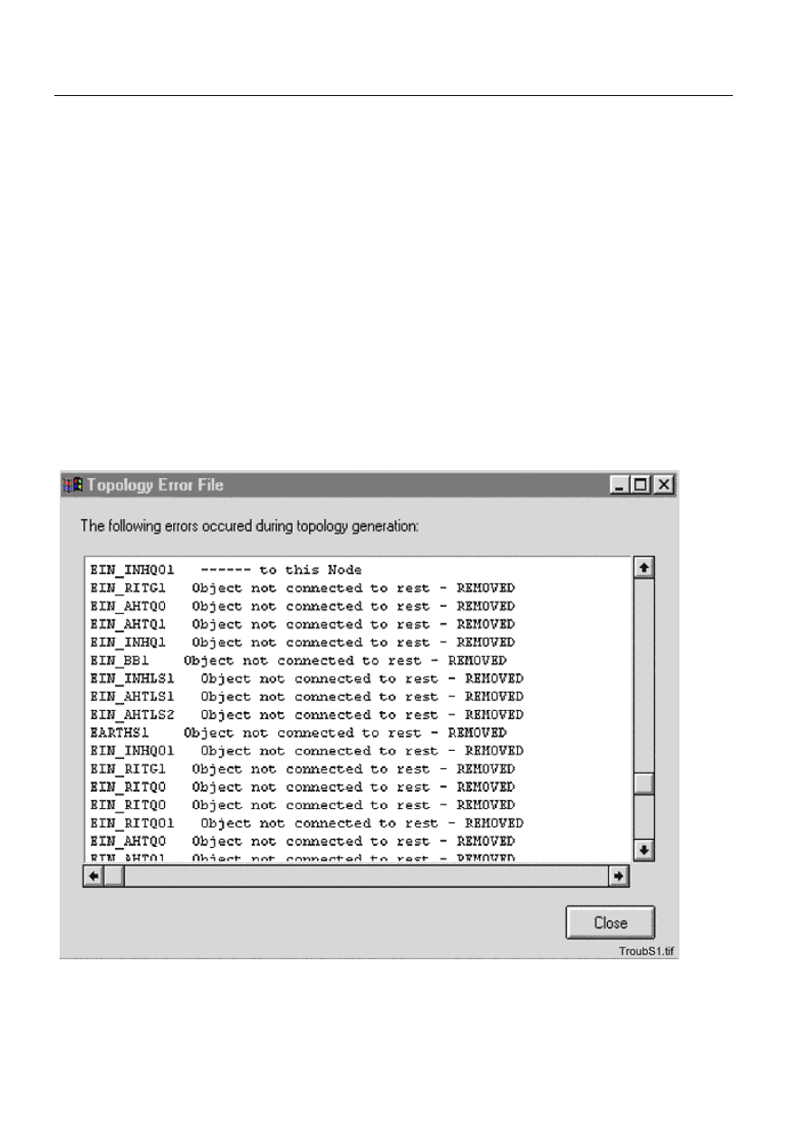
90
1MRS751880-MEN
LIB 500 Configuration Manual
LIB 500
6. Busbar Coloring
Configuration Guide
After start-up the runtime program is waiting for events generated by change of state
of those switching devices, which where included in the topology generation. When
an event is captured, the whole topology situation is recalculated and the new color
values written into the PO of the line and transformer PFs causing the PF to be
redrawn with the new colors.
6.5.2.
Automatic Startup
Once the topology is tested and working properly, the start-up can be made
automatically by activating the field automatic start-up in the Topology Monitor and
by adding the following SCIL code into the "APL_INIT_1:C" command procedure:
#DO BCU_TPSTRT:C
The command procedure BCU_TPSTRT:C starts up the topology.
6.6.
Troubleshooting
During generation some error messages may show up. The most common situations
and their interpretation are described hereafter.
6LWXDWLRQ
)LJ 6LWXDWLRQ
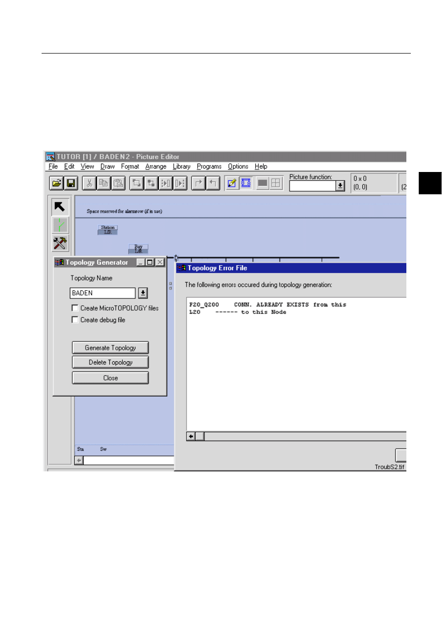
1MRS751880-MEN
LIB 500
91
LIB 500 Configuration Manual
Configuration Guide
6. Busbar Coloring
6
These messages indicate, that during drawing the lines with the SLE, one or more
line ends did not match the connection point of the device PF. Therefore, parts of the
single line diagram are found to be isolated from any electrical voltage source,
which probably is the most common error situation. A quick and helpful solution is
to enter the SLE and move the line ends of the lines shown in the error dialog, and
again connect them to the connection points of the device PF. Store the picture,
reload it, delete all topology files and regenerate the files with TG again.
6LWXDWLRQ
)LJ 6LWXDWLRQ
The busbar isolator PF that is used in a special way to save drawing space, causes
these messages. In this example, the two line segments of busbar left and right of the
isolator, belong to the same line PF. The feeder line going downwards belongs to
another line PF. The topology generator recognises the second connection to the
same line PF and therefore generates these warning, which in this case do not do any
harm. The topology will work properly.

92
1MRS751880-MEN
LIB 500 Configuration Manual
LIB 500
6. Busbar Coloring
Configuration Guide
6.7.
Limitations
Topologies, run simultaneously:
9
Maximum number of nodes per topology:
2048
Used nodes per
CB
1
DS/ES
1
CB with truck
5
3-state switch
3-4
CT/VT
1
2 winding transformer
11
3 winding transformer
16
Line indicator
3
Earth symbol
1
Generator
1
Motor
1
Reactor
1
Capacitor
1
Line (even more
than one element)
1
6.8.
Improvements
The present busbar coloring implementation of MicroSCADA has been improved
comparing to the prior implementations. These improvements are:
• The CB with Truck consisting of three picture functions with the same logical
name, two trucks and one circuit breaker, and also three-State switch consisting
of two picture functions with the same logical name, one disconnector and one
earthing switch, are implemented.
• Bi-directional two and three winding transformers are supported.
• When a topology is stopped by VSCIL dialog “topology monitor” color of all line
segments are set to black.
• Line groups were introduced. Lines can be assigned to different line groups
according to e.g. voltage levels.
• Dashed lines were introduced. Lines can be shown in different shape for e.g.
different voltage levels.
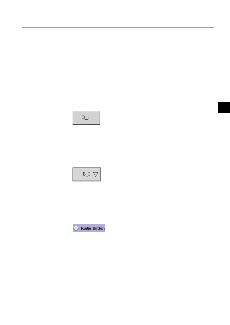
1MRS751880-MEN
LIB 500
93
LIB 500 Configuration Manual
Configuration Guide
7. Component library
7
7. Component
library
7.1.
General
7.1.1.
Overview
This chapter describes the LIB 500 Component Library graphical components.
These standard functions are found in the directory /LIB4/BASE/SLIB/INST. The
sizes of the standard functions (width*height) are given in semi-graphic characters
(16*20 pixels). The size of each standard function is included in the file name; for
example BXI_PB0803.PIC is a push button of size 8*3. Some of the standard
functions can easily be resized to a size not included in the Component Library. The
instructions for this are given in Section 7.3.
7.1.1.1.
Push-button
)LJ 7KHSXVKEXWWRQVWDQGDUGIXQFWLRQ
File name:
BXI_PB*.PIC
File location in package:
SLIB/INST
Sizes available:
2x1, 3x2, 6x3, 7x3, 8x3
7.1.1.2.
Option button
)LJ 7KHRSWLRQEXWWRQVWDQGDUGIXQFWLRQ
File name:
BXI_OB*.PIC
File location in package:
SLIB/INST
Sizes available:
6x3, 7x3, 8x3
7.1.1.3.
Radio button
)LJ 7KHUDGLREXWWRQVWDQGDUGIXQFWLRQ
File name:
BXI_RB*.PIC
File location in package:
SLIB/INST
Sizes available:
1x1, 1x1+0.5, 2x2, 2x2+0.5
1MRS751880-MEN
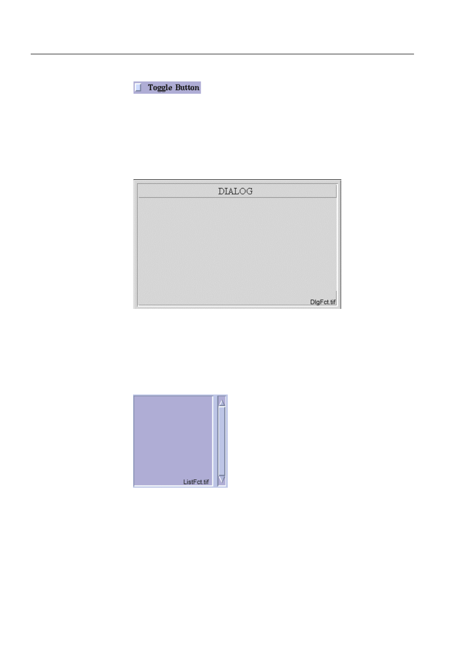
94
1MRS751880-MEN
LIB 500 Configuration Manual
LIB 500
7. Component library
Configuration Guide
7.1.1.4.
Toggle button
)LJ 7KHWRJJOHEXWWRQVWDQGDUGIXQFWLRQ
File name:
BXI_TB*.PIC
File location in package:
SLIB/INST
Sizes available:
1x1, 1x1+0.5, 2x2, 2x2+0.5
7.1.1.5.
Dialog
)LJ 7KHGLDORJVWDQGDUGIXQFWLRQ
File name:
BXI_DI*.PIC
File location in package:
SLIB/INST
Sizes available:
30x15, 30x21, 30x24, 39x24, 39x28, 39x32
7.1.1.6.
List
)LJ 7KHOLVWVWDQGDUGIXQFWLRQ
File name:
BXI_LI*.PIC
File location in package:
SLIB/INST
Sizes available:
13x5, 13x10, 20x10, 20x16, 32x16, 32x20
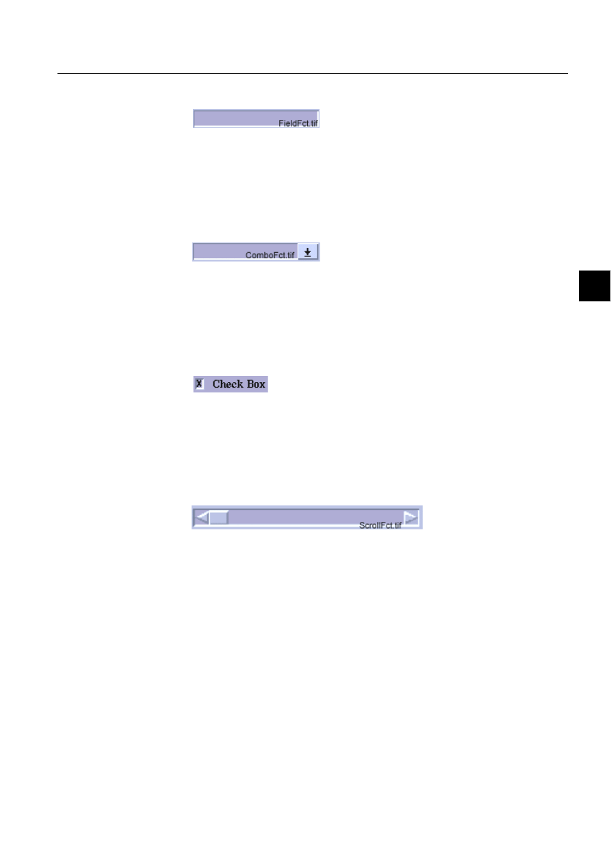
1MRS751880-MEN
LIB 500
95
LIB 500 Configuration Manual
Configuration Guide
7. Component library
7
7.1.1.7.
Field
)LJ 7KHILHOGVWDQGDUGIXQFWLRQ
File name:
BXI_FI*.PIC
File location in package:
SLIB//INST
Sizes available:
3x1, 5x1, 10x1, 13x1, 15x1, 20x1
7.1.1.8.
Combo box
)LJ 7KHFRPERER[VWDQGDUGIXQFWLRQ
File name:
BXI_CB*.PIC
File location in package:
SLIB/INST
Sizes available:
10x1, 13x1, 15x1, 20x1
7.1.1.9.
Check box
)LJ 7KHFKHFNER[VWDQGDUGIXQFWLRQ
File name:
BXI_CH*.PIC
File location in package:
SLIB/INST
Sizes available:
1x1, 1x1+0.5, 2x2, 2x2+0.5
7.1.1.10.
Scroll bar
)LJ 7KHVFUROOEDUVWDQGDUGIXQFWLRQ
File name:
BXI_SB*.PIC
File location in package:
SLIB/INST
Sizes available:
8x1, 16x1, 32x1, 48x1 (horizontal); 1x5, 1x10,
1x16, 1x32 (vertical)
7.1.2.
Description
The Component Library (also called SLIB) is a LIB 500 software package including
the most common graphical components needed in projects or when making new
LIB 500 functions. The purpose of the Component Library is to provide graphical
components for customers and engineers to enable fast and easy building of control
dialogs and other pictures.
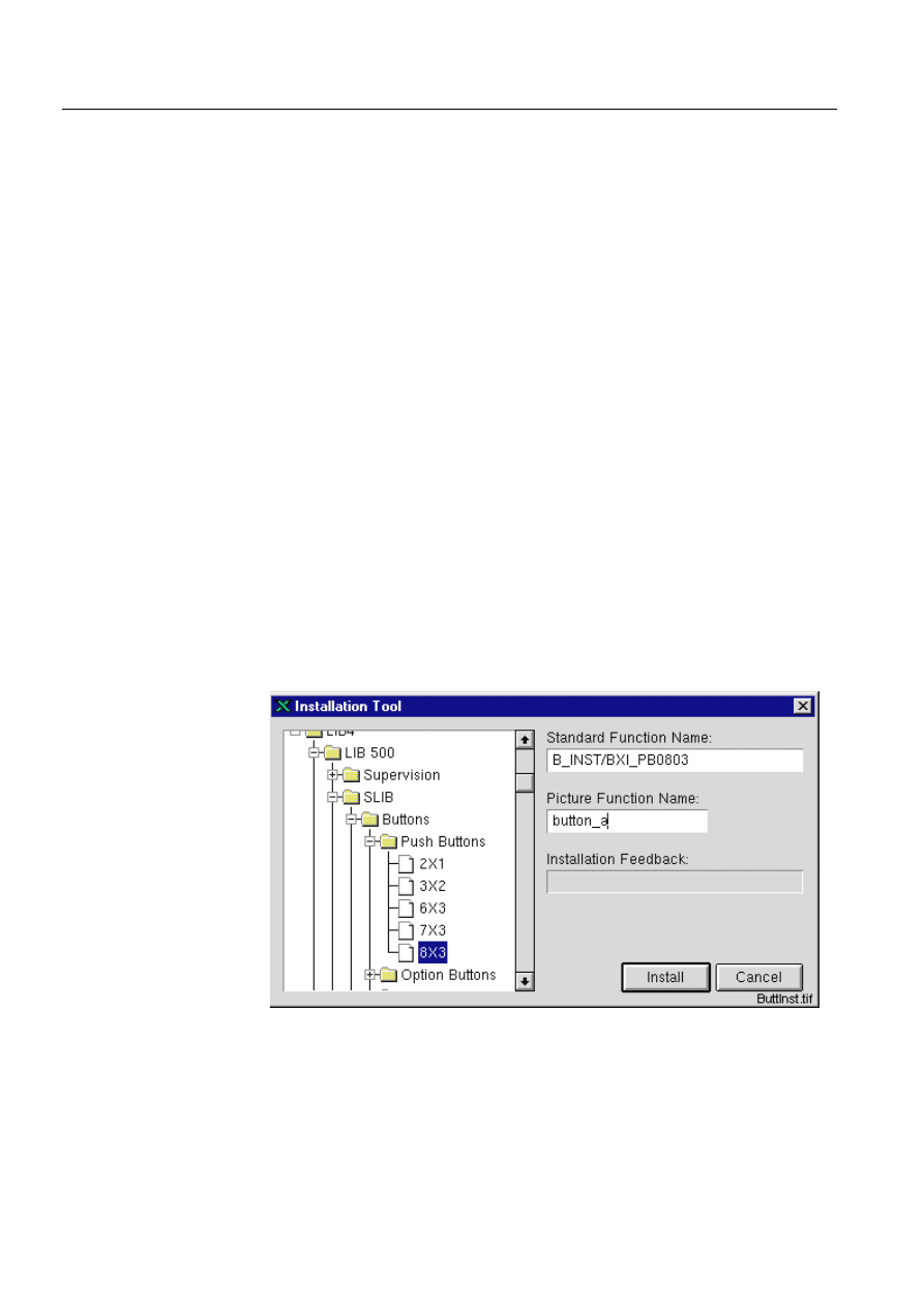
96
1MRS751880-MEN
LIB 500 Configuration Manual
LIB 500
7. Component library
Configuration Guide
7.1.3.
Features/options
• Push button
• Option button
• Radio button
• Toggle button
• Dialog base
• List
• Field
• Combo box
• Check box
• Scroll bar
• Configuration help for all components
7.2.
Installation and configuration
MicroSCADA’s Picture Editor builds a picture using the graphical components of
the Component Library. The installation and configuration have the following
phases:
• The Standard Function Installation Tool (IT) installs the picture function (i.e. the
needed graphical component).
• The Standard Configuration Tool (SCT) configures the picture function. At
configuration the component is given the properties required.
7.2.1.
Push button
)LJ
7KH,7GLDORJRIWKHSXVKEXWWRQ,QVWDOODWLRQ
The following configurable attributes can be changed for the installed object.

1MRS751880-MEN
LIB 500
97
LIB 500 Configuration Manual
Configuration Guide
7. Component library
7
Table 7.2.1-1
The configurable attributes and their descriptions are as
follows
All the attributes listed above can be set via SCIL code as follows:
.SET PF_NAME.ATTRIBUTE = %VALUE,
where PF_NAME is the name of the picture function, ATTRIBUTE is one of the
attributes listed above and %VALUE is the desired value.
The push button has the following methods, which can be executed via SCIL code
as follows:
PF_NAME.METHOD
where PF_NAME is the name of the picture function, and METHOD is the name of
the method. When changing a property (e.g. sensitiveness) of the picture function,
these methods are preferred to direct setting of the corresponding attribute.
Table 7.2.1-2
The push button methods and their descriptions
Attribute
Meaning
Default
LABEL
Text shown on the button
Empty text vector
SENSITIVE
The sensitive state of the button
TRUE
INSTALLED_ON_DIA
LOG
Is the button installed on a dialog or on
main picture background
TRUE
ARMED
Is the button drawn armed at start-up
FALSE
LABEL
The label shown on the button given as a text vector, for example:
“MY”, “BUTTON"
SENSITIVE
The sensitive state of the button. If the button is insensitive, it can
not be activated and the text is shown as dimmed.
INSTALLED_ON_DIA
LOG
States whether the button is installed on a dialog or on main picture
background. The colors of the button are shown differently
depending on this attribute. When this attribute is false, the color of
the button is the same as the color of the base picture function.
ARMED
The button is drawn armed (pressed) at start-up, when this attribute
is set true.
Method
Description
SET_STATE_SENSITIVE
Sets the push button sensitive and redraws the button.
SET_STATE_INSENSITIVE
Sets the push button insensitive and redraws the
button.
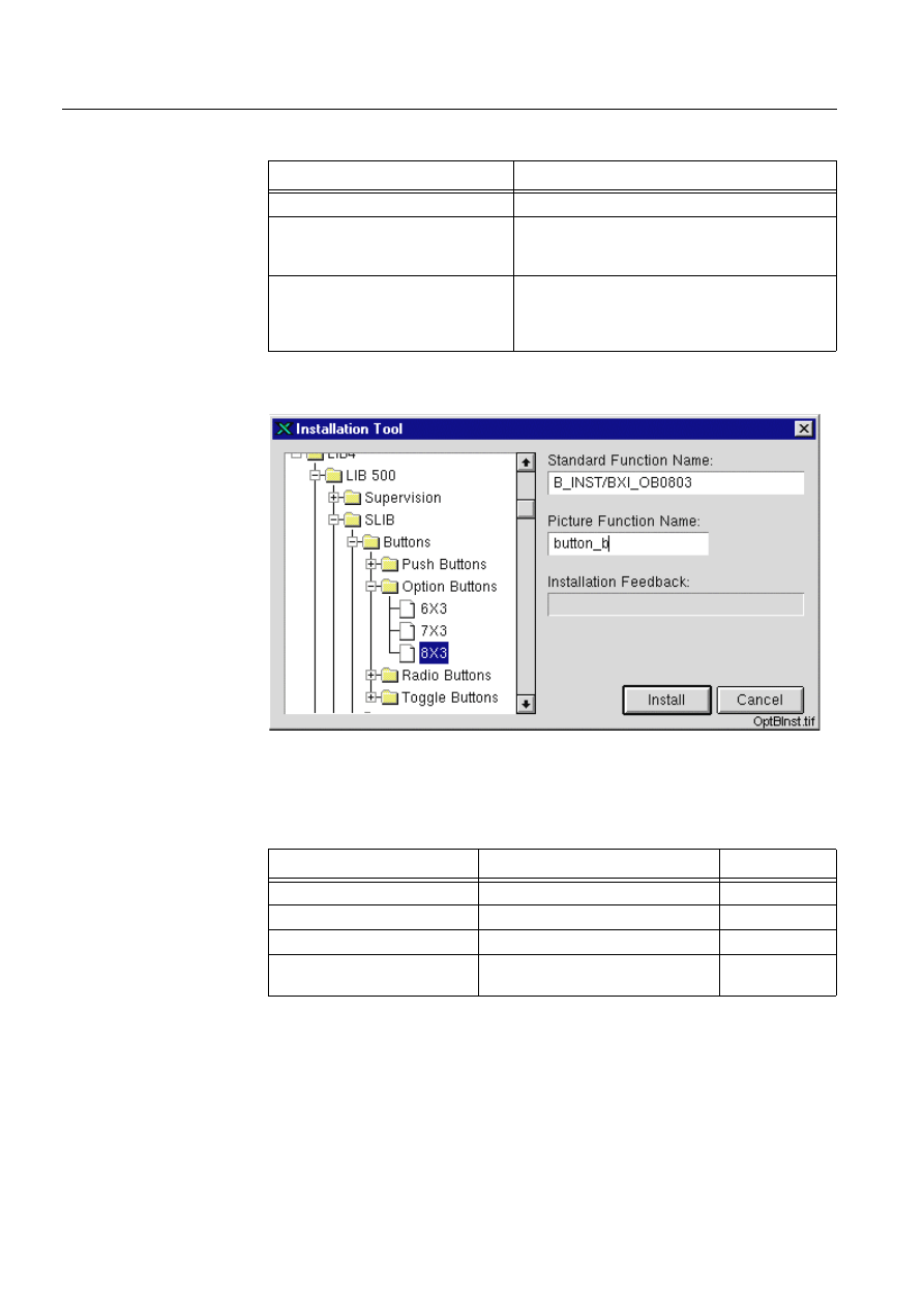
98
1MRS751880-MEN
LIB 500 Configuration Manual
LIB 500
7. Component library
Configuration Guide
Table 7.2.1-3
The user defined programs that can be defined at the
configuration phase
7.2.2.
Option button
)LJ
7KH,7GLDORJRIWKHRSWLRQEXWWRQ,QVWDOODWLRQ
The following configurable attributes can be changed for the installed object.
Table 7.2.2-1
The configurable attributes and their descriptions are as
follows
User Defined Programs
Description
U_ACTIVATE
Executed when the push button is activated.
U_DRAW_FIGURE_SENSITIVE
If you need a graphical label, you can enter the
program for drawing the label here. This method
the label sensitive.
U_DRAW_FIGURE_INSENSITIVE
If you need a graphical label, you can enter the
program for drawing the label here. This method
should contain the SCIL code for drawing the label
insensitive
Attribute
Meaning
Default
MENU_DIMMED_ITEMS
Numbers of the dimmed menu items
Empty vector
LABEL
Text shown on the button
Empty text vector
SENSITIVE
The sensitive state of the button
TRUE
INSTALLED_ON_DIALOG
Is the button installed on a dialog or
on main picture background
TRUE

1MRS751880-MEN
LIB 500
99
LIB 500 Configuration Manual
Configuration Guide
7. Component library
7
All the attributes listed above can be set via SCIL code as follows:
.SET PF_NAME.ATTRIBUTE = %VALUE,
where PF_NAME is the name of the picture function, ATTRIBUTE is one of the
attributes listed above and %VALUE is the desired value.
The option button has the following methods, which can be executed via SCIL code
as follows:
PF_NAME.METHOD
where PF_NAME is the name of the picture function, and METHOD is the name of
the method. When changing a property (e.g. sensitiveness) of the picture function,
these methods are preferred to direct setting of the corresponding attribute.
Table 7.2.2-2
The methods of the option button and their descriptions
Table 7.2.2-3
The user defined programs that can be defined at the
configuration phase
MENU_DIMMED_ITEMS
Number(s) of the menu item(s) to be shown insensitive
on the menu, given as an integer vector, for example:
1,2,3
LABEL
The label shown on the button given as a text vector, for
example:"MY","BUTTON"
SENSITIVE
The sensitive state of the button. If the button is
insensitive, it can not be activated and the text is shown
as dimmed.
INSTALLED_ON_DIALOG
States whether the button is installed on a dialog or on
main picture background. The colors of the button are
shown differently depending on this attribute. When this
attribute is false, the color of the button is the same as
the color of the base picture function.
Method
Description
SET_STATE_SENSITIVE
Sets the push button sensitive and redraws the
button.
SET_STATE_INSENSITIVE
Sets the push button insensitive and redraws the
button.
User Defined Program
Description
U_DEFINE_MENU_STRUCTURE
With this program the structure of the menu to
be shown can be determined. An illustrating
example is given in the program
U_DEFINE_MENU_LABELS
With this program the labels of the menu items
can be given. An illustrating example is given in
the program.
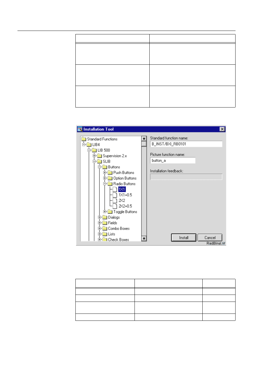
100
1MRS751880-MEN
LIB 500 Configuration Manual
LIB 500
7. Component library
Configuration Guide
7.2.3.
Radio Button
)LJ
7KH,7GLDORJRIWKHUDGLREXWWRQLQVWDOODWLRQ
The following configurable attributes can be changed for the installed object.
Table 7.2.3-1
The configurable attributes and their descriptions are as
follows:
U_DEFINE_MENU_ACTIONS
With this program the action (executed SCIL
code) related to each menu item can be
determined. An illustrating example is given in
the program.
U_DRAW_FIGURE_SENSITIVE
If you need a graphical label, you can enter the
program for drawing the label here. This method
should contain the SCIL code for drawing the
label sensitive.
U_DRAW_FIGURE_INSENSITIVE
If you need a graphical label, you can enter the
program for drawing the label here. This method
should contain the SCIL code for drawing the
label insensitive
User Defined Program
Description
Attribute
Meaning
Default
LABEL
Text shown on the button
Empty text
SENSITIVE
The sensitive state of the button
TRUE
INSTALLED_ON_DIALOG
Is the button installed on a dialog or
on main picture background
TRUE
BUTTON_SET
Is the button drawn set at start-up
FALSE

1MRS751880-MEN
LIB 500
101
LIB 500 Configuration Manual
Configuration Guide
7. Component library
7
All the attributes listed above can be set via SCIL code as follows:
.SET PF_NAME.ATTRIBUTE = %VALUE,
where PF_NAME is the name of the picture function, ATTRIBUTE is one of the
attributes listed above and %VALUE is the desired value.
The radio button has the following methods, which can be executed via SCIL code
as follows:
PF_NAME.METHOD
where PF_NAME is the name of the picture function, and METHOD is the name of
the method. When changing a property (e.g. sensitiveness) of the picture function,
these methods are preferred to direct setting of the corresponding attribute.
Table 7.2.3-2
The methods of the radio button and their descriptions
LABEL
The label shown next to the button given as text, for
example "MY BUTTON”
SENSITIVE
The sensitive state of the button. If the button is
insensitive, it can not be activated and the text is shown
as dimmed
BUTTON_SET
The button is drawn set (pressed) at start-up, when this
attribute is set true.
INSTALLED_ON_DIALOG
States whether the button is installed on a dialog or on
main picture background. The colors of the button are
shown differently depending on this attribute. When this
attribute is false, the color of the button is the same as
the color of the base picture function.
Method
Description
SET_STATE_SENSITIVE
Sets the push button sensitive and redraws the
button
SET_STATE_INSENSITIVE
Sets the push button insensitive and redraws the
button.
SET_STATE_SET
Sets the state of the radio button to set. Not run
when the radio button is insensitive.
SET_STATE_SET_NOTIFY
Equal to the SET_STATE_SET method, but also the
named program U_ACTIVATE_SET is executed.
Not run when the radio button is insensitive.
SET_STATE_UNSET
Sets the state of the radio button to unset. Not run
when the radio button is insensitive.
SET_STATE_UNSET_NOTIFY
Equal to the SET_STATE_UNSET method, but also
the named program U_ACTIVATE_UNSET is
executed. Not run when the radio button is
insensitive.
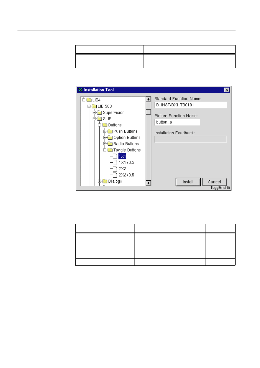
102
1MRS751880-MEN
LIB 500 Configuration Manual
LIB 500
7. Component library
Configuration Guide
Table 7.2.3-3
The user defined programs that can be defined at the
configuration phase
7.2.4.
Toggle button
)LJ
7KH,7GLDORJRIWKHWRJJOHEXWWRQLQVWDOODWLRQ
The following configurable attributes can be changed for the installed object.
Table 7.2.4-1
The configurable attributes and their descriptions are as
follows
User Defined Program
Description
U_ACTIVATE_SET
Executed when the radio button is set.
U_ACTIVATE_UNSET
Executed when the radio button is unset.
Attribute
Meaning
Default
LABEL
Text shown on the button
Empty text
SENSITIVE
The sensitive state of the button
TRUE
INSTALLED_ON_DIALOG
Is the button installed on a dialog or on
main picture background
TRUE
BUTTON_SET
Is the button drawn set at start-up
FALSE

1MRS751880-MEN
LIB 500
103
LIB 500 Configuration Manual
Configuration Guide
7. Component library
7
All the attributes listed above can be set via SCIL code as follows:
.SET PF_NAME.ATTRIBUTE = %VALUE,
where PF_NAME is the name of the picture function, ATTRIBUTE is one of the
attributes listed above and %VALUE is the desired value.
The toggle button has the following methods, which can be executed via SCIL code
as follows:
PF_NAME.METHOD
where PF_NAME is the name of the picture function, and METHOD is the name of
the method. When changing a property (e.g. sensitiveness) of the picture function,
these methods are preferred to direct setting of the corresponding attribute.
Table 7.2.4-2
The methods of the toggle button and their descriptions
LABEL
The label shown next to the button given as text, for
example: "MY BUTTON
SENSITIVE
The sensitive state of the button. If the button is
insensitive, it can not be activated and the text is shown
as dimmed.
INSTALLED_ON_DIALOG
States whether the button is installed on a dialog or on
main picture background. The colors of the button are
shown differently depending on this attribute. When this
attribute is false, the color of the button is the same as
the color of the base picture function.
BUTTON_SET
The button is drawn set (pressed) at start-up, when this
attribute is set true.
Method
Description
SET_STATE_SENSITIVE
Sets the toggle button sensitive and redraws the
button.
SET_STATE_INSENSITIVE
Sets the toggle button insensitive and redraws the
button.
SET_STATE_SET
Sets the state of the toggle button to set. Not run
when the toggle button is insensitive.
SET_STATE_SET_NOTIFY
Equal to the SET_STATE_SET method, but also the
named program U_ACTIVATE_SET is executed.
Not run when the toggle button is insensitive.
SET_STATE_UNSET
Sets the state of the toggle button to unset. Not run
when the toggle button is insensitive.
SET_STATE_UNSET_NOTIFY
Equal to the SET_STATE_UNSET method, but also
the named program U_ACTIVATE_UNSET is
executed. Not run when the toggle button is
insensitive.
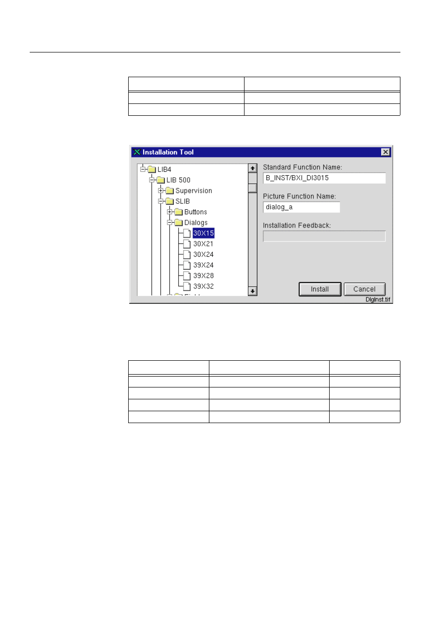
104
1MRS751880-MEN
LIB 500 Configuration Manual
LIB 500
7. Component library
Configuration Guide
Table 7.2.4-3
The user defined programs that can be defined at the
configuration phase
7.2.5.
Dialog
)LJ
7KH,7GLDORJRIWKHGLDORJ,QVWDOODWLRQ
The following configurable attributes can be changed for the installed object.
Table 7.2.5-1
The configurable attributes and their descriptions are as
follows:
All the attributes listed above can be set via SCIL code as follows:
.SET PF_NAME.ATTRIBUTE = %VALUE,
User Defined Programs
Description
U_ACTIVATE_SET
Executed when the toggle button is set.
U_ACTIVATE_UNSET
Executed when the toggle button is unset.
Attribute
Meaning
Default
MOVABLE
Can the dialog be moved
TRUE
SHOW_INFOBAR
Is the infobar shown
TRUE
TITLE
The dialog title
“DIALOG”
WINDOW_NAME
The name of the dialog window
“DUMMY”
MOVABLE
Defines if the dialog can be moved by dragging from the infobar
on the top of the dialog.
SHOW_INFOBAR
Determines whether the infobar is shown or not.
TITLE
The dialog title shown at headerbar.
WINDOW_NAME
The window name in which the dialog is shown. Needed by the
dialog, when it is moved on screen.
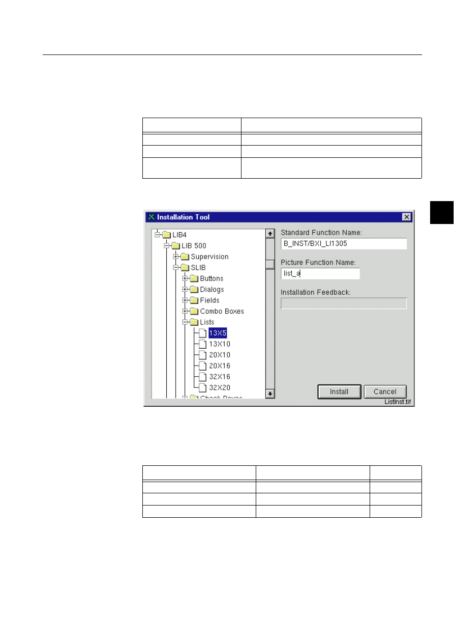
1MRS751880-MEN
LIB 500
105
LIB 500 Configuration Manual
Configuration Guide
7. Component library
7
where PF_NAME is the name of the picture function, ATTRIBUTE is one of the
attributes listed below and %VALUE is the desired value. The dialog has the
following methods, which can be executed via SCIL code as follows:
Table 7.2.5-2
The user defined programs that can be defined at the
configuration phase
7.2.6.
List
)LJ
7KH,7GLDORJRIWKHOLVW,QVWDOODWLRQ
The following configurable attributes can be changed for the installed object.
Table 7.2.6-1
The configurable attributes and their descriptions are as
follows:
User Defined Programs
Description
U_OPEN
Executed when the dialog is shown.
U_CLOSE
Executed when the dialog is closed.
U_MOVED
Executed when the dialog headerbar is selected with the
mouse.
Attribute
Meaning
Default
SENSITIVE
The sensitive state of the list.
TRUE
SELECTABLE
Can items be selected from the list
TRUE
MULTI_SELECT
The selecting policy.
FALSE

106
1MRS751880-MEN
LIB 500 Configuration Manual
LIB 500
7. Component library
Configuration Guide
All the attributes listed above can be set via SCIL code as follows:
.SET PF_NAME.ATTRIBUTE = %VALUE,
where PF_NAME is the name of the picture function, ATTRIBUTE is one of the
attributes listed above and %VALUE is the desired value.
The list has the following methods, which can be executed via SCIL code as follows:
PF_NAME.METHOD
where PF_NAME is the name of the picture function, and METHOD is the name of
the method. When changing a property (e.g. sensitiveness) of the picture function,
these methods are preferred to direct setting of the corresponding attribute
INSTALLED_ON_DIALOG
Is the list installed on a dialog or on
main picture background
TRUE
LIST_ITEMS
The selectable items shown on the
list.
Empty vector
DOUBLE_CLICK_INTERVAL
Time interval between two
consecutive clicks.
500 ms
Attribute
Meaning
Default
SENSITIVE
The sensitive state of the list. If the list is insensitive it
can not be activated and the text is shown as dimmed.
SELECTABLE
Defines if an item can be selected from the list. If this
attribute is false, no selection can be made and the
line is not shown highlighted.
MULTI_SELECT
The selecting policy. If the multi select is true multiple
items can be selected by clicking or dragging. When
clicking or dragging the selection of the items will be
toggled. If multi select is false only one item can be
selected by clicking or dragging and the selected item
can not be unselected. If multi select is false the
double click function can be used.
INSTALLED_ON_DIALOG
States whether the list is installed on a dialog or on
main picture background. The colors of the list are
shown differently depending on this attribute.
LIST_ITEMS
The selectable items shown on the list. Elements must
be given as elements of a text vector, for example
"ITEM1","ITEM2". When set by SCIL code, this
attribute must also be a text vector.
DOUBLE_CLICK_INTERVAL
The maximum time between two clicks not to be
interpreted as a double click given in milliseconds.
The attribute has no effect when MULTI_SELECT is
true.
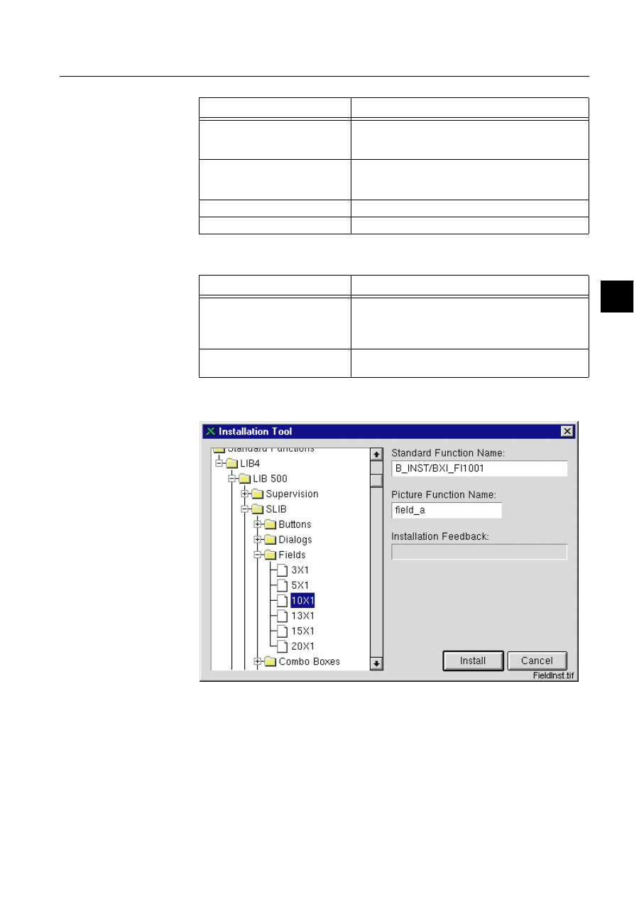
1MRS751880-MEN
LIB 500
107
LIB 500 Configuration Manual
Configuration Guide
7. Component library
7
Table 7.2.6-2
The methods of the list and their descriptions
Table 7.2.6-3
The user defined programs that can be defined at the
configuration phase
7.2.7.
Field
)LJ
7KH,7GLDORJRIWKHILHOGLQVWDOODWLRQ
The following configurable attributes can be changed for the installed object.
Method
Description
UPDATE
Updates the list. Can be used for example when a new
value has been set. Named program
U_VALUE_CHANGED is not executed.
UPDATE_NOTIFY
Otherwise same as the UPDATE method, but named
the program U_SELECT is also executed (not when the
list is insensitive).
SET_STATE_SENSITIVE
Sets the list sensitive.
SET_STATE_INSENSITIVE
Sets the list insensitive.
User Defined Program
Description
U_SELECT
Executed when a selection is made. If items are
selected by dragging this programs is executed when
the mouse is released. Executed when the
.UPDATE_NOTIFY method is used.
U_DOUBLE_CLICK
Executed when a double click is made. This program is
not executed if multiselect is true.

108
1MRS751880-MEN
LIB 500 Configuration Manual
LIB 500
7. Component library
Configuration Guide
Table 7.2.7-1
The configurable attributes and their descriptions are as
follows
Attribute
Meaning
Default
SENSITIVE
The sensitive state of the field
TRUE
EDITABLE
Can values be entered from the keyboard TRUE
UPPER_CASE
Is a text value set to upper case.
FALSE
EXPRESSION
Is the value an expression.
FALSE
INSTALLED_ON_DIALOG
Is the field is installed on a dialog or on
main picture background
TRUE
DATA_TYPE
Data type of the value of the field.
TEXT
VALUE
The default value of the field.
Empty text
ALIGNMENT
Alignment of the field
LEFT
MAX_LENGTH
Maximum number of characters/ digits
invoked to the input field.
40
UPDATE_INTERVAL
The time interval of cyclical updating of
the field in seconds.
If set to zero, the field is not updated
cyclically.
0
NR_OF_DECIMALS
Number of decimals of a real type value.
3
SENSITIVE
The sensitive state of the field. If the field is insensitive a
value can’t be entered and the text is shown as dimmed.
EDITABLE
Defines if the value can be entered from the keyboard.
UPPER_CASE
If this attribute is true and the attribute DATA_TYPE is set
as TEXT, the value is set to upper case letters
EXPRESSION
Defines if the value is an expression, for example a
variable name. If true then the value of the expression is
shown
INSTALLED_ON_DIALOG
States whether the field is installed on a dialog or on
main picture background. The colors of the list are shown
differently depending on this attribute.
DATA_TYPE
Defines the data type of the input value. Possible values:
TEXT, INTEGER, REAL.
VALUE
The default value shown in the field. Either an expression
or a text string. If an expression is given, the attribute
EXPRESSION must be set to true. Otherwise the default
value given here is converted to the data type
determined by the attribute DATA_TYPE, if possible.
When VALUE is changed at run-time, it is up to the
programmer to ensure that the value set is of correct
data type.
ALIGNMENT
Alignment of the text. Possible values: LEFT, CENTER,
RIGHT
MAX_LENGTH
Maximum number of characters/digits invoked to the
input field.
NR_OF_DECIMALS
Number of decimals of a real type value

1MRS751880-MEN
LIB 500
109
LIB 500 Configuration Manual
Configuration Guide
7. Component library
7
All the attributes listed above can be set via SCIL code as follows:
.SET PF_NAME.ATTRIBUTE = %VALUE,
where PF_NAME is the name of the picture function, ATTRIBUTE is one of the
attributes listed above and %VALUE is the desired value.
The field has the following methods, which can be executed via SCIL code as
follows:
PF_NAME.METHOD
where PF_NAME is the name of the picture function, and METHOD is the name of
the method. When changing a property (e.g. sensitiveness) of the picture function,
these methods are preferred to direct setting of the corresponding attribute.
Table 7.2.7-2
The methods of the field and their descriptions
Table 7.2.7-3
The user defined programs that can be defined at the
configuration phase
Method
Description
UPDATE
Updates the field. Can be used for example when a
new value has been set. Named program
U_VALUE_CHANGED is not executed.
UPDATE_NOTIFY
Otherwise same as the UPDATE method, but
named the program U_VALUE_CHANGED is also
executed.
REDRAW
Redraws the field. Can be used for example when
one of the configuration attributes has been set.
SET_STATE_SENSITIVE
Sets the field sensitive.
SET_STATE_INSENSITIVE
Sets the field insensitive.
SET_STATE_EDITABLE
Enables the user to enter a value from the
keyboard.
SET_STATE_NON_EDITABLE
Disables the user to enter a value from the
keyboard.
SET_ALIGNMENT_LEFT
Sets text alignment to left
SET_ALIGNMENT_CENTER
Sets text alignment to center
SET_ALIGNMENT_RIGHT
Sets text alignment to right
User Defined Program
Description
U_VALUE_CHANGED
Executed when a new value entered to the field is
different from the previous value. Executed when
the .UPDATE_NOTIFY method is used.
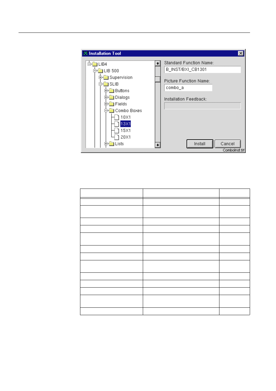
110
1MRS751880-MEN
LIB 500 Configuration Manual
LIB 500
7. Component library
Configuration Guide
7.2.8.
Combo box
)LJ
7KH,7GLDORJRIWKHFRPERER[LQVWDOODWLRQ
The following configurable attributes can be changed for the installed object.
Table 7.2.8-1
The configurable attributes and their descriptions are as
follows:
* = depends on the size of the standard function
Attribute
Meaning
Default
SENSITIVE
The sensitive state of the combo box.
TRUE
EDITABLE
Can values be entered from the
keyboard
TRUE
UPPER_CASE
Is a text value set to upper case.
FALSE
EXPRESSION
Is the value an expression.
FALSE
INSTALLED_ON_DIALOG
Is the combo box is installed on a dialog
or on main picture background
TRUE
DATA_TYPE
Data type of the value of the field.
TEXT
VALUE
The default value of the combo box.
Empty text
SELECTED_INDEX
The number (index) of the selected item
(value).
0
LIST_ITEMS
The selectable items shown on the list.
Empty vector
LIST_PICTURE_NAME
The name of the list picture.
*
ALIGNMENT
Alignment of the field
LEFT
MAX_LENGTH
Maximum number of characters/digits
invoked to the input field.
40
NR_OF_DECIMALS
Number of decimals of a real type value. 3

1MRS751880-MEN
LIB 500
111
LIB 500 Configuration Manual
Configuration Guide
7. Component library
7
All the attributes listed above can be set via SCIL code as follows:
.SET PF_NAME.ATTRIBUTE = %VALUE,
where PF_NAME is the name of the picture function, ATTRIBUTE is one of the
attributes listed below and %VALUE is the desired value.
The combo box has the following methods, which can be executed via SCIL code as
follows:
SENSITIVE
The sensitive state of the combo box. If the combo box is
insensitive it can not be activated and the text is shown
as dimmed.
EDITABLE
Defines if the value can be entered from the keyboard.
The value can be selected from the list even if this
attribute is false.
UPPER_CASE
If this attribute is true and the attribute DATA_TYPE is set
as TEXT, the value is set to upper case letters.
EXPRESSION
Defines if the value is an expression, for example a
variable name. If true then the value of the expression is
shown.
INSTALLED_ON_DIALOG
States whether the combo box is installed on a dialog or
on main picture background. The colors of the combo
box are shown differently depending on this attribute
DATA_TYPE
Defines the data type of the input value. Possible values:
TEXT, INTEGER, REAL.
VALUE
The default value shown in the field. Either an expression
or a text string. If an expression is given, the attribute
EXPRESSION must be set to true. Otherwise the default
value given here is converted to the data type
determined by the attribute DATA_TYPE, if possible.
When VALUE is changed at run-time, it is up to the
programmer to ensure that the value set is of correct
data type.
SELECTED_INDEX
The number (index) of the selected item (value).
LIST_ITEMS
The selectable items shown on the list. Elements must
be given as elements of a text vector, for example:
"ITEM1","ITEM2". When set by SCIL code, this attribute
must also be a text vector.
LIST_PICTURE_NAME
The name of the list picture. The list picture can be
changed to a list with correct length depending on
number of list items. List pictures are named LIB4/BASE/
SLIB/USE/BXU_CB*.PIC, the last two characters define
the height of the list in sg characters. If the created
picture is wanted to be independent of the Component
Library, combo box list pictures must be copied to
another directory and renamed. The new name must be
written to this attribute.
ALIGNMENT
Alignment of the text.
MAX_LENGTH
Maximum number of characters/digits invoked to the
input field.
NR_OF_DECIMALS
Number of decimals of a real type value.

112
1MRS751880-MEN
LIB 500 Configuration Manual
LIB 500
7. Component library
Configuration Guide
PF_NAME.METHOD
where PF_NAME is the name of the picture function, and METHOD is the name of
the method. When changing a property (e.g. sensitiveness) of the picture function,
these methods are preferred to direct setting of the corresponding attribute.
Table 7.2.8-2
The methods of the combo box and their descriptions
Table 7.2.8-3
The user defined programs that can be defined at the
configuration phase
Method
Description
UPDATE
Updates the combo box. Can be used for example
when a new value has been set. Named program
U_VALUE_CHANGED is not executed.
UPDATE_NOTIFY
Otherwise same as the UPDATE method, but
named the program U_VALUE_CHANGED is also
executed.
REDRAW
Redraws the combo box. Can be used for example
when one of the configuration attributes has been
set.
ERASE_LIST
Erases the list.
SET_STATE_SENSITIVE
Sets the combo box sensitive.
SET_STATE_INSENSITIVE
Sets the combo box insensitive.
SET_STATE_EDITABLE
Enables the user to enter a value from the
keyboard.
SET_STATE_NON_EDITABLE
Disables the user to enter a value from the
keyboard.
SET_ALIGNMENT_LEFT
Sets the text alignment to left.
SET_ALIGNMENT_CENTER
Sets the text alignment to center.
SET_ALIGNMENT_RIGHT
Sets the text alignment to right.
User Defined Program
Description
U_VALUE_CHANGED
Executed when a new value entered in the field or
selected the list is different from the previous value.
Executed when the .UPDATE_NOTIFY method is
used.
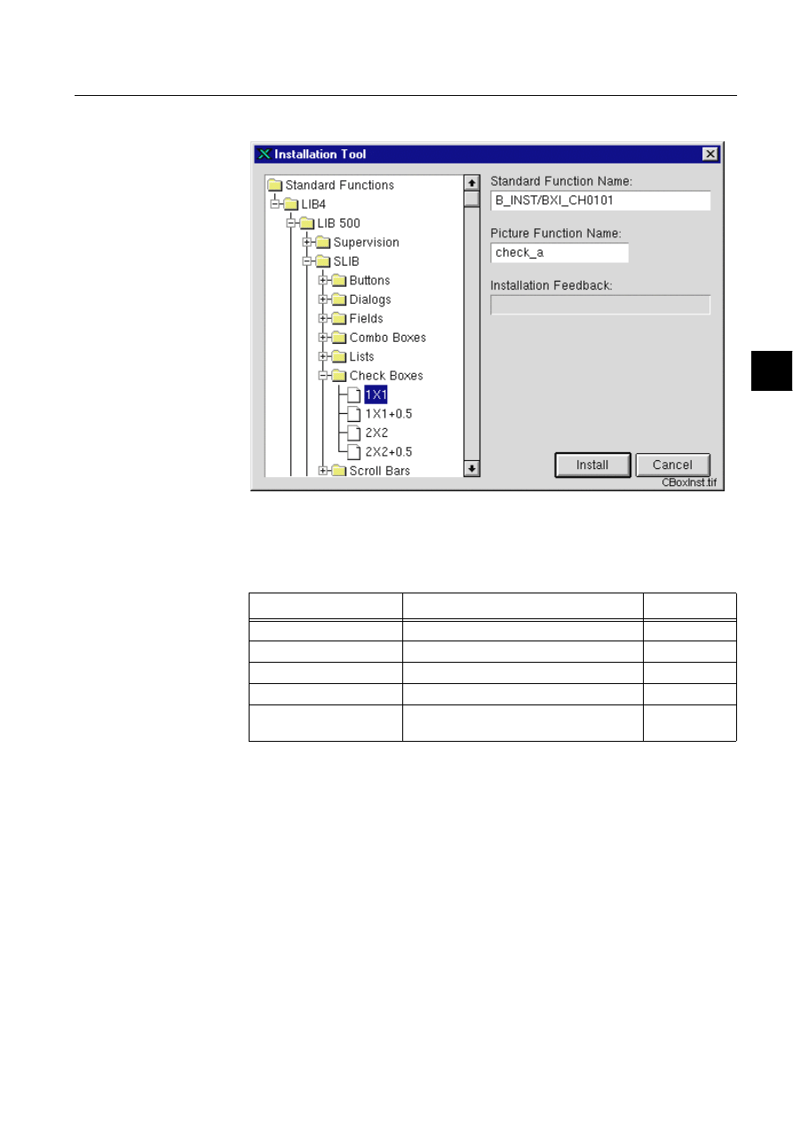
1MRS751880-MEN
LIB 500
113
LIB 500 Configuration Manual
Configuration Guide
7. Component library
7
7.2.9.
Check box
)LJ
7KH,7GLDORJRIWKHFKHFNER[LQVWDOODWLRQ
The following configurable attributes can be changed for the installed object.
Table 7.2.9-1
The configurable attributes and their descriptions are as
follows:
Attribute
Meaning
Default
MARK TYPE
The type of the selection mark.
CROSS
LABEL
The label shown next to the check box
Empty text
SELECTED
Is the check box shown selected at start-up. FALSE
SENSITIVE
The sensitive state of the combo box.
TRUE
INSTALLED_ON_DIALOG
Is the check box is installed on a dialog or on
main picture background
TRUE
MARK TYPE
The type of the mark that indicates the selection state of the check box.
A selector type attribute, values are: CROSS (X), DOT (.) and CHECK
(V)
LABEL
The label shown next to the check box given as text, for example: "MY
BOX"

114
1MRS751880-MEN
LIB 500 Configuration Manual
LIB 500
7. Component library
Configuration Guide
The check box has the following methods, which can be executed via SCIL code as
follows:
PF_NAME.METHOD
where PF_NAME is the name of the picture function, and METHOD is the name of
the method. When changing a property (e.g. sensitiveness) of the picture function,
these methods are preferred to direct setting of the corresponding attribute.
Table 7.2.9-2
The methods of the check box and their descriptions
Table 7.2.9-3
The user defined programs that can be defined at the
configuration phase
SELECTED
The check box is drawn selected at start-up, when this attribute is set
true.
SENSITIVE
The sensitive state of the combo box. If the combo box is insensitive it
can not be activated and the text is shown as dimmed
INSTALLED_ON_
DIALOG
States whether the check box is installed on a dialog or on main picture
background. The colors of the check box are shown differently
depending on this attribute.
Method
Description
SET_STATE_SENSITIVE
Sets the check box sensitive and redraws the check
box.
SET_STATE_INSENSITIVE
Sets the check box insensitive and redraws the check
box.
SET_STATE_SELECTED
Sets the state of the check box to selected. Not run
when the check box is insensitive.
SET_STATE_SELECTED_
NOTIFY
Equal to the SET_STATE_SELECTED method, but
also the named program U_ACTIVATE_SET is
executed. Not run when the check box is insensitive.
SET_STATE_UNSELECTED
Sets the state of the check box to unselected. Not run
when the check box is insensitive.
SET_STATE_UNSELECTED_NOTI
FY
Equal to the SET_STATE_UNSELECTED method,
but also the named program
U_ACTIVATE_UNSELECTED is executed. Not run
when the check box is insensitive.
User Defined Program
Description
U_ACTIVATE_SELECTED
Executed when the check box is selected.
U_ACTIVATE_UNSELECTED
Executed when the check box is unselected.
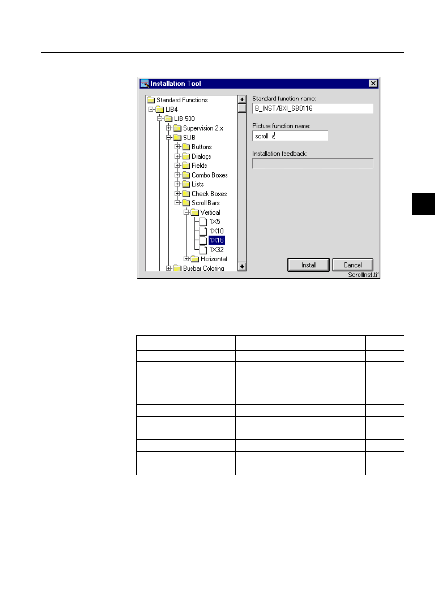
1MRS751880-MEN
LIB 500
115
LIB 500 Configuration Manual
Configuration Guide
7. Component library
7
7.2.10.
Scroll bar
)LJ 7KH,7GLDORJRIWKHVFUROOEDULQVWDOODWLRQ
The following configurable attributes can be changed for the installed object.
Table 7.2.10-1 The configurable attributes and their descriptions are as
follows:
Attribute
Meaning
Default
SENSITIVE
The sensitive state of the scroll bar.
TRUE
INSTALLED_ON_DIALOG
Is the scroll bar is installed on a dialog or on
main picture background
TRUE
VALUE
The value of the scroll bar.
0
MAXIMUM
The maximum value of the scroll bar
50
MINIMUM
The minimum value of the scroll bar
1
SLIDER_SIZE
The size of the slider.
5
INCREMENT
The size of the increment.
1
PAGE_INCREMENT
The size of the page increment.
5
INITIAL_DELAY
The length of the initial delay
100 ms
REPEAT_DELAY
The length of the repeat delay
30 ms

116
1MRS751880-MEN
LIB 500 Configuration Manual
LIB 500
7. Component library
Configuration Guide
All the attributes listed above can be set via SCIL code as follows:
.SET PF_NAME.ATTRIBUTE = %VALUE,
where PF_NAME is the name of the picture function, ATTRIBUTE is one of the
attributes listed below and %VALUE is the desired value.
The scroll bar has the following methods, which can be executed via SCIL code as
follows:
PF_NAME.METHOD
where PF_NAME is the name of the picture function, and METHOD is the name of
the method. When changing a property (e.g. sensitiveness) of the picture function,
these methods are preferred to direct setting of the corresponding attribute
SENSITIVE
The sensitive state of the scroll bar. If the scroll bar is
insensitive, it can not be activated.
INSTALLED_ON_DIALOG
States whether the scroll bar is installed on a dialog or on
main picture background. The colors of the scroll bar are
shown differently depending on this attribute.
VALUE
The value of the scroll bar. The value changes when the
scroll bar is scrolled. The value range is from minimum to
(maximum - slider size). Normally the value is read. But it
can also be set, and if then the scroll bar is updated, it’s
position shows the value.
MAXIMUM
The maximum value of the scroll bar given as a real
number.
MINIMUM
The minimum value of the scroll bar given as a real
number.
SLIDER_SIZE
The size of the slider given as a real number.
INCREMENT
The amount by which the value increases or decreases
when the slider is moved by one increment (e.g. with the
arrow-shaped scroll keys). Increment is given as a real
number.
PAGE_INCREMENT
The amount by which the value increases or decreases
when the slider is moved by one page increment (e.g. by
clicking under or above the slider). Page increment is
given as a real number
INITIAL_DELAY
The amount of time in milliseconds to wait before starting
continuous slider movement when the bar is scrolled by
keeping the mouse pressed. Initial delay is given as an
integer.
REPEAT_DELAY
The amount of time in milliseconds to wait between
subsequent slider movements. Repeat delay is given as
an integer.
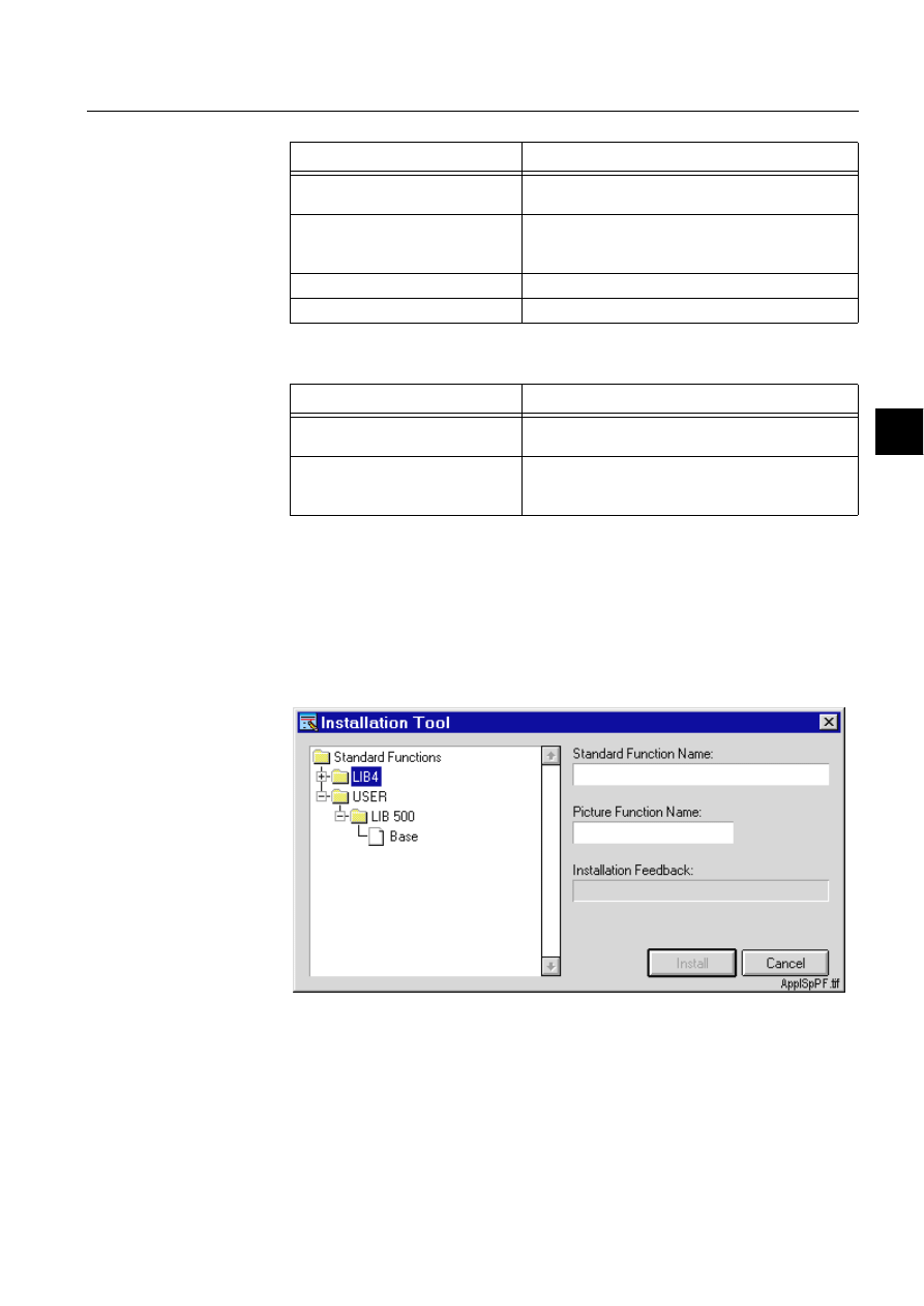
1MRS751880-MEN
LIB 500
117
LIB 500 Configuration Manual
Configuration Guide
7. Component library
7
Table 7.2.10-2 The methods of the check box and their descriptions
Table 7.2.10-3 The user defined programs that can be defined at the
configuration phase
7.2.11.
Application specific picture functions
Configuring application specific picture function
There is a mechanism for introducing application specific picture functions to the
object tree of the installation tool. The user can locate a modified picture function in
the
DSOPRG directory of the application. Modified picture functions are visible in
the installation tree.
)LJ 7KH,7GLDORJRIWKH$SSOLFDWLRQ6SHFLILF3LFWXUH)XQFWLRQ
LQVWDOODWLRQ
Files that are to be displayed in the installation tree can be copied to the directory
DSO>DSSQDPH@DSOPRGLQVW by the user. When the installation tool is opened, all
files matching the condition INDEX4_* are searched from this directory. [app.
name] is the name of the application. The file INDEX4_
>[@.TXT, where x is a free
Method
Description
UPDATE
Updates the scroll bar. Can be used for example
when a new value has been set.
UPDATE_NOTIFY
Equal to the UPDATE method, but named programs
U_VALUE_CHANGED and U_VALUE_CHANGED_
RELEASE are executed.
SET_STATE_SENSITIVE
Sets the scroll bar sensitive.
SET_STATE_INSENSITIVE
Sets the scroll bar insensitive.
User Defined Program
Description
U_VALUE_CHANGED
Executed when the value has changed. Executed
when the UPDATE_NOTIFY method is used.
U_VALUE_CHANGED_RELEASE
Executed when the value has changed and the
mouse is released Executed when the
UPDATE_NOTIFY method is used.

118
1MRS751880-MEN
LIB 500 Configuration Manual
LIB 500
7. Component library
Configuration Guide
extension, defines the installation ’path’ that is used to make the picture function
visible in the installation tree. For example, picture function presented in attached
picture is defined using the path /USER/LIB 500/Base.
To make an application specific picture function, follow these steps:
1. Copy a picture function (e.g. base picture function) files from library to
aplmod4 directory. The files are listed in INDEX4_n.TXT. Copy also the file
INDEX4_n.TXT.
2. Make necessary changes to the picture function (.pic file) using Picture Editor
(and Text Editor when text file)
3. Edit the picture function "path" for the installation tree (in INDEX4_n.TXT).
The path defines the branch names and leaf name where the new function will
be displayed in the tree.
4. Rename the picture function files and make the corresponding changes in
INDEX4_n.TXT so that it is possible to use also the original picture function.
After these operations, new picture function should be available in the installation
tool.
([DPSOH
Original picture function entry in INDEX4_B1.TXT:
/LIB4/LIB 500/Base for 4.0.3
@SFNAME = "B_INST/BGI_BASE2"
@CONF_FILE = "B_INST/BGI_BASE2.DAT"
@INSTALLPOSX = 1
@INSTALLPOSY = 1
Modified picture function entry in INDEX4_U1.TXT
/USER/LIB 500/Base
@SFNAME = "B_INST/BGI_BASEU"
@CONF_FILE = "B_INST/BGI_BASEU.DAT"
@INSTALLPOSX = 1
@INSTALLPOSY = 1
The following modified files should be located in
DSO>DSSQDPH@DSOPRGLQVW
after example configuration:
bgi_baseu.dat
BGI_BASEU.PIC
index4_U1.txt
7.3.
Modification of components
7.3.1.
General
Although several standard function sizes are available in LIB 500 4.0.3, application
specific sizes may be needed. This chapter contains the instructions to resize the
following graphical components: push button, option button, dialog, field, combo
box, list and scroll bar. It is not recommended to resize components that were
QRW
mentioned above.
Some components (e.g. field) can be resized only to one direction, while other
components (e.g. list) can be resized both horizontally and vertically. In the
following chapters, instructions for each graphical component are given, preceded

1MRS751880-MEN
LIB 500
119
LIB 500 Configuration Manual
Configuration Guide
7. Component library
7
by a section common for all components. Creating a push button of size 10x4 (i.e.
resize from a 8x3 button) is used as an example in the following chapters.
7.3.2.
Common instructions
The same rules apply to modifying SLIB components as to changing any LIB 5xx
standard functions. The “original” standard functions should not be modified, but
they should be copied to the APLMOD4 directory of the current application and the
copies should be modified.
Furthermore, to enable installing of any new standard functions (i.e. standard
functions that are not included in the LIB 5xx package in question, for example a
resized Component Library push button), they must be included in the
MLIB_INDEX.TXT file located in LIB4/BASE/BBONE/USE.
To modify a SLIB component, the following steps must be taken:
&RS\WKHVWDQGDUGIXQFWLRQ
The standard function (.PIC file) must be copied from LIB4/BASE/SLIB/INST to
APL/.../APLMOD4/INST. If the size of the standard function is to be changed, the
copy must also be renamed so that the last four characters indicate the size of the
standard function.
In our example case we must copy the file LIB4/BASE/SLIB/INST/
BXI_PB0803.PIC to APL/.../APLMOD4/INST/BXI_PB1004.PIC
(GLWWKHVWDQGDUGIXQFWLRQLQGH[ILOH
All the Component Library standard functions are listed in the file
INDEX4_B7.TXT. This file is initially located in LIB4/BASE/SLIB/INST and then
copied to LIB4/BASE/BBONE/INST by the installation program. To add a new
standard function, do the following:
• Open the file to LIB4/BASE/BBONE/INST/INDEX4_B7.TXT to a text editor
• Add a new three-line block for the new standard function. In our example we
would add the block:
LIB4/LIB 500/SLIB/Buttons/Push Buttons/10X4
@SFNAME = "B_INST/BXI_PB1004"
@CONF_FILE = "B_INST/BXI_PB.DAT"
• Copy the edited file to LIB4/BASE/SLIB/INST to get a back-up
• Restart the MicroSCADA in order to recreate the MLIB_INDEX.TXT file.
0RGLI\WKHQHZVWDQGDUGIXQFWLRQWRWKHQHZVL]H
This is explained, as far as components are concerned, in the next chapter. In our
example, we would open the file APL/.../APLMOD4/INST/BXI_PB1004.PIC to the
MicroSCADA Picture Editor and modify the things as explained in the due section.
7.3.3.
Component specific instructions
7.3.3.1.
Push button and option button
The following instructions apply to both push button and option button. To resize,
do the following:

120
1MRS751880-MEN
LIB 500 Configuration Manual
LIB 500
7. Component library
Configuration Guide
• In the DRAW program change the standard function id to give the new size (line
4: ...SET .ID = "PB_WxH" or ...SET .ID = "OB_WxH", where W is the new
width and H the new height).
• In the DRAW program change the variables W and H to give the new size (lines 6
and 7)
• Resize the key to fit the new size
7.3.3.2.
Dialog
To resize a dialog standard function, do the following:
• In the DRAW program change the standard function id to give the new size (line
4: ...SET .ID = "DI_WxH", where W is the new width and H the new height).
• In the DRAW program change the variables WD and HD to give the new size
(lines 6 - 7)
• Move and resize the headerbar and information bar keys to fit the new size
7.3.3.3.
Field
To resize a field standard function, do the following (note that only the width of the
field can be changed):
• In the DRAW program change the standard function id to give the new size (line
5: ...SET .ID = "FI_Wx1", where W is the new width).
• In the DRAW program change the variable W to give the new width (line 8)
• Resize the key to fit the new size
• Change the width of the internal field windows to be the same as the new width.
Note that there are 12 windows on top of each other, the width of all of them must
be changed.
7.3.3.4.
Combo box
Combo box consists of two pictures: the actual standard function picture and the
combo box list picture, both of which should have the same width. The list pictures
are located in the directory LIB4/BASE/SLIB/USE and are named BXU_CB*.PIC,
where * represents four characters indicating the size of the list picture, just like with
all SLIB pictures. The list picture can be resized both horizontally and vertically,
while only the width of the combo box standard function can be changed. Of course
you can just modify the list picture to get for example a higher list.
To resize a combo box standard function, do the following:
6WDQGDUGIXQFWLRQSLFWXUH
• In the DRAW program, change the standard function id to give the new size (line
5: ...SET .ID = "CB_Wx1", where W is the new width).
• In the DRAW program change the variable W to give the new width (line 8)
• Resize the key to fit the new size
• Change the width of the internal field windows to be the same as the new width.
Note that there are 12 windows on top of each other, the width of all of them must
be changed.

1MRS751880-MEN
LIB 500
121
LIB 500 Configuration Manual
Configuration Guide
7. Component library
7
&RPERER[OLVWSLFWXUH
• Copy an existing list picture from LIB4/BASE/SLIB/USE to APL/.../
APLMOD4/USE and rename it to fit the new size (last four characters = width
and height).
• In the DRAW program of the new list picture, change the variable LIST_ID to fit
the new size (line 4)
• In the DRAW program change the variable WIDTH and HEIGHT to give the new
width and height (lines 7-8)
• Move and resize the list and scroll bar keys to fit the new size
• Select the internal figure window on the upper left part of the list picture and edit
the size of it’s background to fit the new size
7.3.3.5.
List
To resize a list standard function does the following:
• In the DRAW program change the standard function id to give the new size (line
4: ...SET .ID = "LI_WxH", where W is the new width and H the new height).
• In the DRAW program change the variable WIDTH and HEIGHT to give the new
width and height (lines 7-8)
• Move and resize the list and scroll bar keys to fit the new size
• Select the internal figure window on the upper left part of the picture and edit the
size of its background to fit the new size
7.3.3.6.
Scroll bar
There are two kinds of scroll bar standard functions; horizontal and vertical. In case
of a horizontal scroll bar only the width can be changed and in the case of a vertical
scroll bar only the height can be changed.
To resize a scroll bar standard function, do the following:
+RUL]RQWDOVFUROOEDU
• In the DRAW program change the standard function id to give the new size (line
5: ...SET .ID = "CB_Wx1", where W is the new width).
• In the DRAW program change the variable WIDTH to give the new width (line 8)
• Resize the keys to fit the new size
9HUWLFDOVFUROOEDU
• In the DRAW program change the standard function id to give the new size (line
5: ...SET .ID = "CB_1xH", where H is the new height).
• In the DRAW program change the variable HEIGHT to give the new height (line
8)
• Resize the keys to fit the new size

122
1MRS751880-MEN
LIB 500 Configuration Manual
LIB 500
7. Component library
Configuration Guide
7.4.
Using components
7.4.1.
General
The purpose of the Component Library is to provide a set of commonly used
graphical components to enable fast and easy building and modification of
MicroSCADA pictures. To illustrate the use of Component Library, a practical
example is provided in this chapter. Also some hints about picture building and
application programming are provided.
7.4.2.
Environmental requirements
The Component Library standard functions utilise some general MicroSCADA
parameters and drawing procedures, which have to be provided in a certain way.
Therefore, there are the following environmental requirements: when using
Component Library standard functions, one the following components have to be
installed:
• LIB 500 Base picture function, or
• Component Library dialog base picture function.
7.4.3.
Example of building a dialog
In the following example, a dialog showing the alarm state of an indication process
object is built. This dialog also contains a button to acknowledge the alarm. A button
to open this dialog is installed to a station picture. In the following it is assumed that
the name of the dialog is TEST_DIAL and the name of the process object is
TEST_OBJ (index 10). This object could be, for example, a breaker position
indication object.
In order to build the dialog, open the MicroSCADA Picture Editor and select the
picture function mode. After opening the Installation Tool, select the path LIB4-
BASE-DIALOGS-30x24 to install the dialog base. At installation give the dialog
base a name, for example DIAL_BASE1. After this open the Configuration Tool to
give the dialog base configuration presented in the following table:
Table 7.4.3-1
The dialog base configuration
The next step is to install three push buttons; one for alarm acknowledgement, one
for closing the dialog and one for opening a help dialog, which is good to have in
any MicroSCADA dialog. So, as the next step win install three 8*3 push buttons;
TEST_BUT1, TEST_BUT2 and TEST_BUT3, which are configured as follows:
Attribute
Value
WINDOW_NAME
TEST_WIN
MOVABLE
TRUE
SHOW_INFOBAR
TRUE
TITLE
"Process Object Alarm Dialog"
1MRS751880-MEN
LIB 500
123
LIB 500 Configuration Manual
Configuration Guide
7. Component library
7
Table 7.4.3-2
TEST_BUT1 (alarm acknowledgement)
8VHUGHILQHGSURJUDP8B$&,9$7(
;acknowledge alarm
#SET TEST_OBJ:PAR10 = 1
Table 7.4.3-3
TEST_BUT2 (close dialog)
8VHUGHILQHGSURJUDP8B$&,9$7(
;close this dialog
!ERASE TEST_WIN
Table 7.4.3-4
TEST_BUT3 (open help dialog)
8VHUGHILQHGSURJUDP8B$&,9$7(
;input for help dialog (help file name)
@HELP_FILE = “TEST_DIAL.HLP"
;open help dialog
!WIN_NAME ROOT/MLIB_HELPW
!WIN_PIC ROOT/MLIB_HELPW B_USE/BGU_HELPA
!WIN_POS ROOT/MLIB_HELPW (21,9)
!SHOW ROOT/MLIB_HELPW
In order to enable identifying the process object, we can install two fields, which are
to show the Object Identification and Object Text of the process object. The size of
these fields is 20x1 and the name may be e.g. TEST_FI1 and TEST_FI2. The fields
are given the following configuration:
Attribute
Value
SENSITIVE
TRUE
ARMED
FALSE
INSTALLED_ON_DIALOG
TRUE
LABEL
"Ackn.","Alarm"
Attribute
Value
SENSITIVE
TRUE
ARMED
FALSE
INSTALLED_ON_DIALOG
TRUE
LABEL
"Close.",""
Attribute
Value
SENSITIVE
TRUE
ARMED
FALSE
INSTALLED_ON_DIALOG
TRUE
LABEL
"Help."

124
1MRS751880-MEN
LIB 500 Configuration Manual
LIB 500
7. Component library
Configuration Guide
Table 7.4.3-5
TEST_FI1 (Object Identification)
Table 7.4.3-6
TEST_FI2 (Object Text)
As the last components, two check boxes will be installed to indicate the alarm and
the acknowledgement of the process objects. These check boxes are of size 1*1 and
named TEST_ CHCK1 and TEST_CHCK2. They are to act as indications only and
not to be selectable. The configurations of the check boxes is as follows:
Table 7.4.3-7
TEST_CHCK1 (Object alarm)
Attribute
Value
DATA_TYPE
TEXT
EXPRESSION
TRUE
ALIGNMENT
LEFT
MAX_LENGTH
30
NR_OF_DECIMALS
3
VALUE
TEST_OBJ:POI10
SENSITIVE
TRUE
UPDATE_INTERVAL
0
UPPER_CASE
FALSE
EDITABLE
FALSE
Attribute
Value
DATA_TYPE
TEXT
EXPRESSION
TRUE
ALIGNMENT
LEFT
MAX_LENGTH
30
NR_OF_DECIMALS
3
VALUE
TEST_OBJ:POX10
SENSITIVE
TRUE
UPDATE_INTERVAL
0
UPPER_CASE
FALSE
INSTALLED_ON_DIALOG
TRUE
EDITABLE
FALSE
Attribute
Value
MARK_TYPE
CROSS
SENSITIVE
FALSE
SELECTED
FALSE
LABEL
Alarm acknowledged
INSTALLED_ON_DIALOG
TRUE
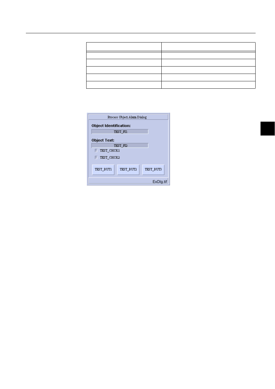
1MRS751880-MEN
LIB 500
125
LIB 500 Configuration Manual
Configuration Guide
7. Component library
7
Table 7.4.3-8
TEST_CHCK2 (Alarm acknowledgement)
After all the picture functions have been installed and configured, and after some
explanatory texts have been written, the picture lay-out looks as in Figure 7.4.3.-1.
)LJ
([DPSOHGLDORJOD\RXW
The next thing to do is to write the SCIL code that connects the graphical
components to the process object. This program code can be written for example to
the U_OPEN program of the dialog picture function. This program is a user-defined
program and can be accessed via the Standard Configuration Tool. The following
code is written to this program (the functionality of the code is explained in the
comment lines, see SCIL programming manual for further details):
;when process object attribute value changes
#ON TEST_OBJ:E10 #BLOCK
;if alarming, set check box 1 selected, else set it unselected
#IF TEST_OBJ:PAL10 == 1 #THEN TEST_CHCK1.SET_STATE_SELECTED
#ELSE TEST_CHCK1.SET_STATE_UNSELECTED
;if acknowledged, set check box 2 selected and ackn. button insensitive
;else set check box 1 unselected and ackn. button sensitive
#IF TEST_OBJ:PAR10 == 1 #THEN #BLOCK
TEST_CHCK2.SET_STATE_SELECTED
TEST_BUT1.SET_STATE_INSENSITIVE
#BLOCK_END
#ELSE #BLOCK
TEST_CHCK2.SET_STATE_UNSELECTED
TEST_BUT1.SET_STATE_SENSITIVE
#BLOCK_END
#BLOCK_END
;execute the event object above
#EXEC TEST_OBJ:E10
The final step is to write the help text in the file TEST_DIAL.HLP and to insert a
button to the station (or any other) picture to open the dialog we have just created.
Attribute
Value
MARK_TYPE
CROSS
SENSITIVE
FALSE
SELECTED
FALSE
LABEL
Object alarming
INSTALLED_ON_DIALOG
TRUE
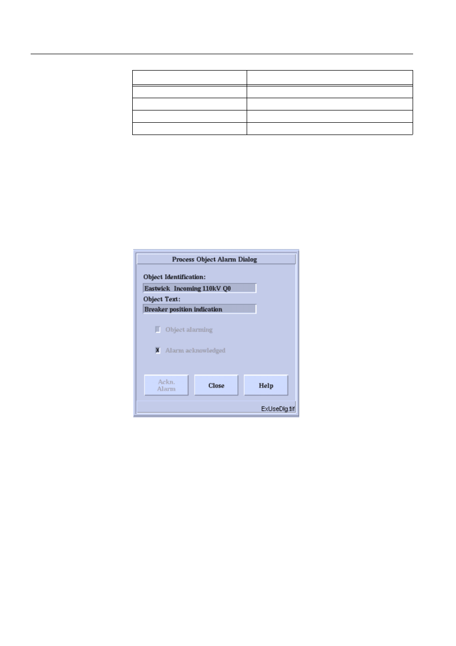
126
1MRS751880-MEN
LIB 500 Configuration Manual
LIB 500
7. Component library
Configuration Guide
Table 7.4.3-9
This button is given the following configuration
8VHUGHILQHGSURJUDP8B$&,9$7(
;open the test dialog
!WIN_NAME TEST_WIN
!WIN_PIC TEST_WIN TEST_DIAL
!WIN_POS TEST_WIN (20,15)
!WIN_BG_COLOR TEST_WIN (“M”,1)
!SHOW TEST_WIN
When clicking this button and provided that the process object exists, we should get
a dialog that looks as follows (texts and other attribute values depend of course on
the object used):
)LJ
([DPSOHGLDORJLQXVH
This example described above is of course just a simple example of creating a
picture using the SLIB components, but it gives the basic means and correct methods
for using the graphical components. When building and editing control dialogs and
other pictures, it is recommended to used LIB 5xx pictures as a reference and as a
model for look & feel.
Attribute
Value
SENSITIVE
TRUE
ARMED
FALSE
INSTALLED_ON_DIALOG
FALSE
LABEL
"Open Test.","Dialog"
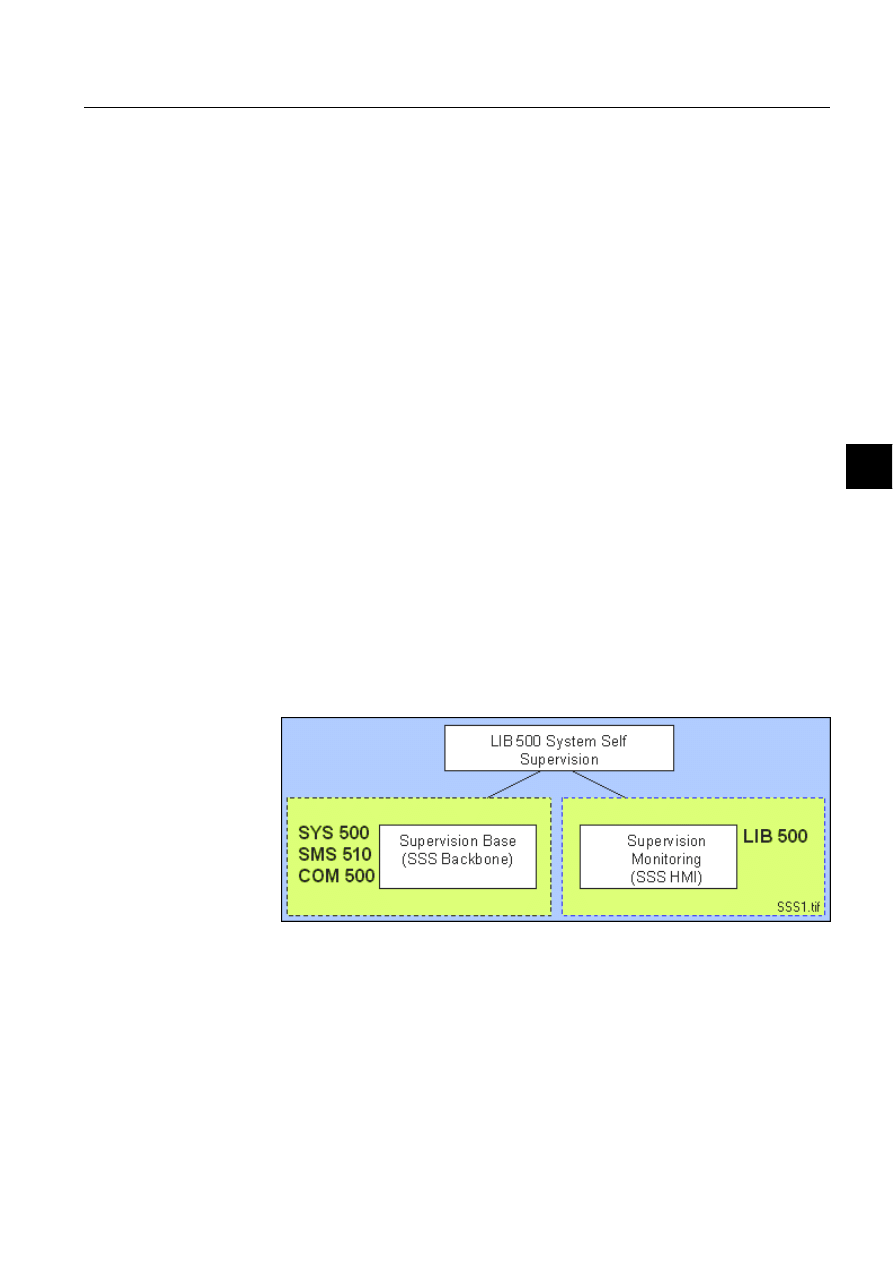
1MRS751880-MEN
LIB 500
127
LIB 500 Configuration Manual
Configuration Guide
8. System self supervision
8
8.
System self supervision
8.1.
General
8.1.1.
Overview and description
The LIB 500 System Self Supervision (SSS) is used with MicroSCADA systems for
supervising and monitoring of the system. It provides with the status information of
hardware and software as well as picture functions for the supervision of system
objects.
LIB 500 System Self Supervision consists of
• Supervision Base (SSS Backbone)
• Supervision Monitoring (SSS HMI)
Supervision Base and Supervision Monitoring are to be seen as independent
components. The SSS Backbone functionality includes the basic functionality of the
System Self Supervision and it can be used in several system environments. The SSS
HMI provides with the monitoring part of System Self Supervision and it can be
used only in the LIB 500 environment.
The Supervision Base is an independent component that operates also without
presence of the Supervision Monitoring part and thus, it can be used in various
system environments (SYS 500, SMS 510 and COM 500).
The Supervision Monitoring includes the HMI, which provides a set of supervised
picture functions that can be inserted to the system supervision picture. The
Supervision Monitoring part is attached to the Supervision Base through the process
database i.e. indications for the object’s state is used as an interface between the
Supervision Base and the Supervision Monitoring part. The Supervision Monitoring
part can be used only in the LIB 500 environment.
)LJ
6\VWHP&RQFHSW'HVLJQRIWKH/,%6\VWHP6HOI6XSHUYLVLRQ
8.1.2.
Features/options
8.1.2.1.
Supervision base (SSS Backbone)
The main function of SSS Backbone is to provide the mechanism for routing of
supervision information into the MicroSCADA process database from the process
devices and other supervised objects.
1MRS751880-MEN

128
1MRS751880-MEN
LIB 500 Configuration Manual
LIB 500
8. System self supervision Configuration Guide
The Supervision Base consists of ((see Fig. 8.1.2.1.-1)):
• Process objects that receives system messages from MicroSCADA
communication units, indicates the object’s state and generates events and alarms
• Command procedures, event channels and time channels that perform the actual
supervision routing and information interpreting (Supervision Routing
Interpreter)
• Text file for language dependent signal texts in the database and for log events
shown in the Supervision Log
• Initialization files for storing the configuration data and event filtering
information
• Text file that contain the configuration data for the general parameters of the
System Self Supervision
• Text files that contain the source code for the command procedures
• Text files related to System Configuration Manager
• Viewer for log events (Supervision Log)
It includes
• All the common system message points (i.e. process objects that receives system
message information from a communication unit)
• Event channels for predefined events
• Command procedures, event and time channels for handling supervision routing
and information interpreting of system messages and events
• Indication points for handling supervision routing and information interpreting of
system messages and events
It provides the status information of the
• Hardware
• System components
• Communication equipment
• Process control
• Protection units
Supervision Base reflects the image of the system configuration. The system
configuration itself can be done either by means of
1. System Configuration Tool
2. By a set of SCIL configuration files (e.g. in SYS_BASCON.COM,
PC_NETS.COM and other SCIL files) together with event channels and
command procedures in the report database.
Supervision Base functions are common for MicroSCADA base system and all the
functions that are related to the Supervision Base are created by using the System
Configuration Manager.
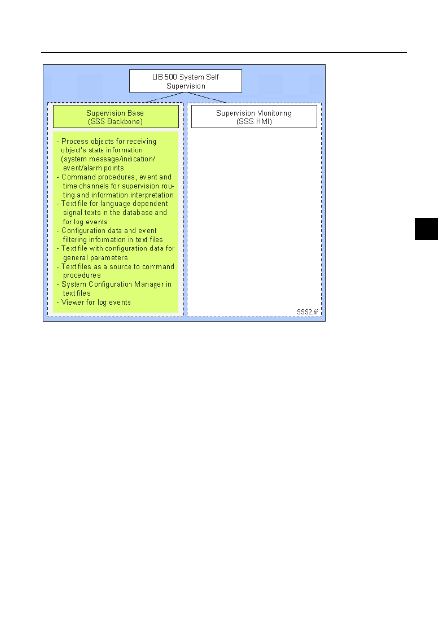
1MRS751880-MEN
LIB 500
129
LIB 500 Configuration Manual
Configuration Guide
8. System self supervision
8
)LJ 6\VWHP&RQFHSW'HVLJQRIWKH666%DFNERQHSDUW
8.1.2.2.
System monitoring (SSS HMI)
The main function of SSS HSI is to provide the monitoring picture functions for
supervision of running system, through the system supervision picture.
System Monitoring provides following components (see Fig. 8.1.2.2.-1):
• Monitor
• Base System
• Application
• NET
• NET line
• Station
• LON Clock Master
• Printer
Each component i.e. picture function can be installed on the system supervision
picture and configured according to the supervised system. The state of the
supervised system objects (i.e. normal state, alarm etc.) is represented by color
indications.
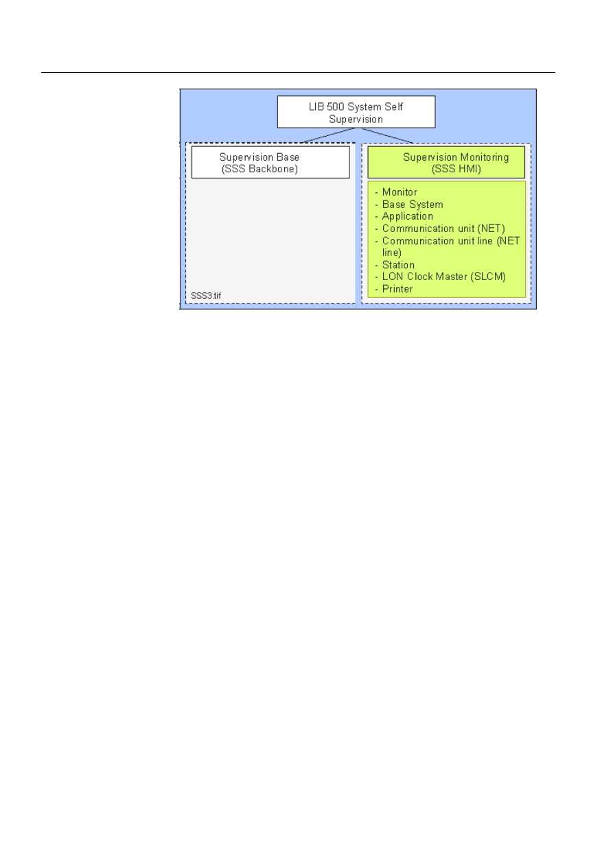
130
1MRS751880-MEN
LIB 500 Configuration Manual
LIB 500
8. System self supervision Configuration Guide
)LJ 6\VWHP&RQFHSW'HVLJQRIWKH666+6,SDUW
8.1.3.
System requirements
• MicroSCADA 8.4.3 or later
• System Self Supervision of LIB 500 4.0.3
8.2.
System Self Supervision overview
The LIB 500 System Self Supervision is to be seen as event based follow-up of
process data, although some of the status information is based on the predefined
events (e.g. station suspension) or a time related follow-up of process (e.g. state of
NET). The collected event information by System Self Supervision can be shown in
the HSI of MicroSCADA: Event List, Alarm List and Supervision Log Viewer, see
(see Fig. 8.2.-1).
The operation of the LIB 500 System Self Supervision is mainly based on the
information of the system objects itself, system messages produced by the
MicroSCADA communication unit (NET) and predefined events produced by the
MicroSCADA itself.
This chapter describes the operational basis of the System Self Supervision
functions as in general form.
The Supervision Base functionality, including also installation and configuration
part of the Supervision Base functionality, is described more detailed in Section 8.3.
Please note that if the application specific modifications to the Supervision Base are
needed more information can be found from the Section 8.4.
The Supervision Monitoring functionality is described in Section 8.5 onward.
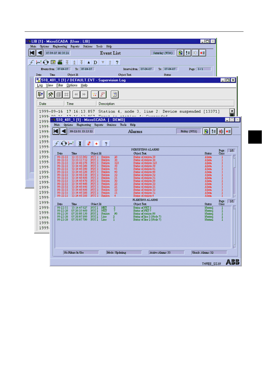
1MRS751880-MEN
LIB 500
131
LIB 500 Configuration Manual
Configuration Guide
8. System self supervision
8
)LJ ,QIRUPDWLRQFROOHFWHGE\6\VWHP6HOI6XSHUYLVLRQVKRZQLQ+0,
8.2.1.
System configuration
In the system configuration of MicroSCADA, the environment of process devices,
communication nodes and communication lines are presented.
8.2.1.1.
Base system
Each MicroSCADA base system contains a set of base system objects, which
specify the MicroSCADA base system itself and its environment. They also define

132
1MRS751880-MEN
LIB 500 Configuration Manual
LIB 500
8. System self supervision Configuration Guide
logical connections to NETs and other MicroSCADA base systems and their
applications.
During operation, the base system objects reside in the primary memory of the
MicroSCADA base system computer. The MicroSCADA base system objects are
created with SCIL (Supervisory Control Implementation Language) commands,
when the MicroSCADA base system is started. They can be added and modified
during operation.
8.2.1.2.
Communication system
Communication system objects and their attributes specify NET configuration and
handle process communication. They give the NET unit an image of the
communication lines as well as an image of connected devices. System object
definitions can be used as one of the functional basis of system supervision
functions. The process devices (stations) contain their own configuration
definitions, which must be regarded in the MicroSCADA configuration.
Communication between process devices and MicroSCADA process database
requires that both the base system object and communication system object
definitions are consistent.
8.2.2.
Data flow of System Self Supervision
For each event to be displayed in the Human System Interface (HSI) by the System
Self Supervision, the incoming event data is first converted by using different
components. The data flow of System Self Supervision consists of following
components, see (see Fig. 8.2.2.-1)
1. Process device(s)
2. Communication node(s)
3. Supervision Routing Interpreter
4. System Configuration Manager
5. Initialization and Log Files
6. MicroSCADA process database.
In the following chapters is each of these component described more exactly.
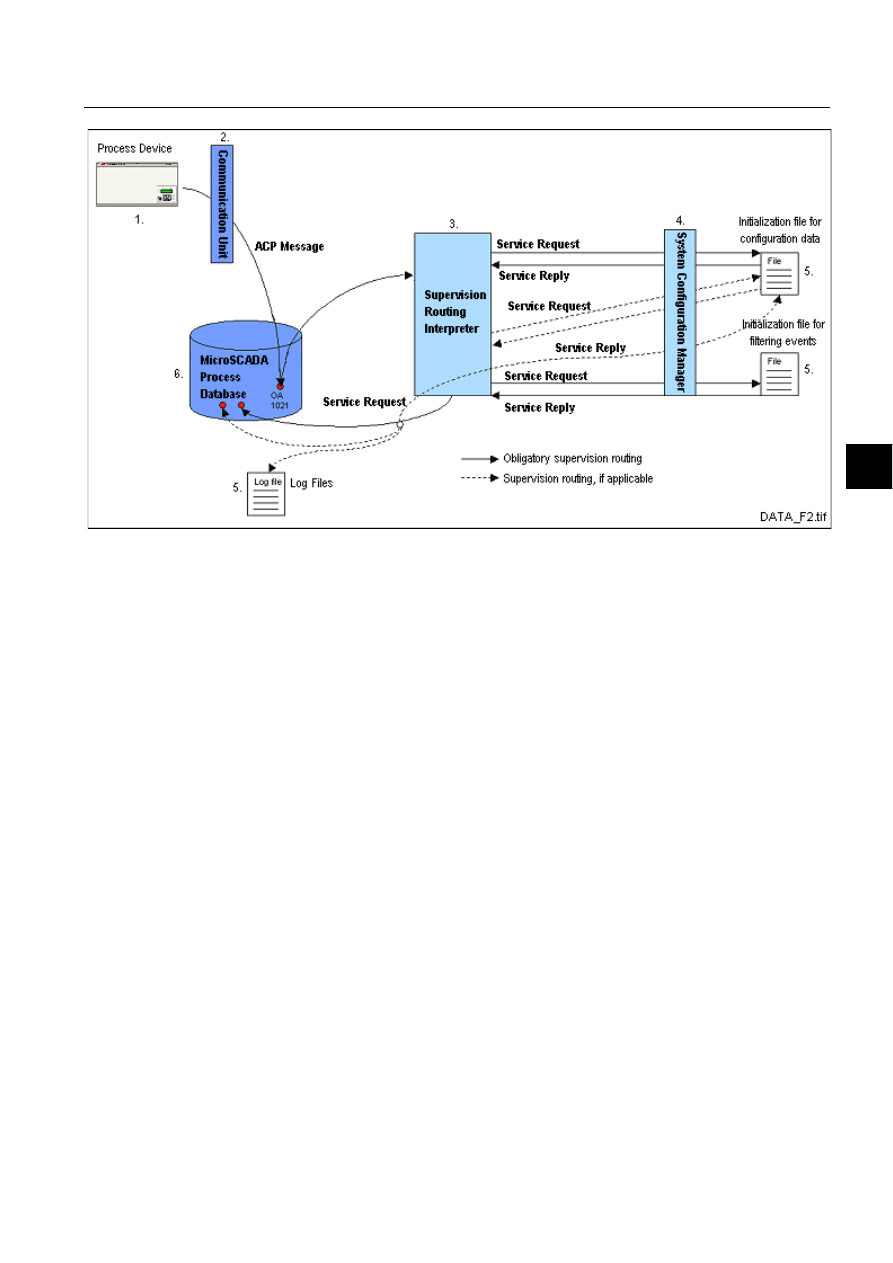
1MRS751880-MEN
LIB 500
133
LIB 500 Configuration Manual
Configuration Guide
8. System self supervision
8
)LJ
6\VWHP6HOI6XSHUYLVLRQ'DWD)ORZ
8.2.3.
Process devices
Process devices are used for gathering the process data (measurement value, state of
breaker or earth switch) and perming the control commands. The process
communication system connects the application software in the MicroSCADA base
systems with the process devices (stations).
System Self Supervision functionality can be used for collecting the data from
process devices of the following types: REX, LMK, SPA, IEC, DNP, RTU and SPI.
8.2.4.
Communication nodes
The process communication is handled by a number of parallel or serially
interconnected communication units, also called NETs. A NET is a communication
program running directly on the CPU of a PC (PC-NETs) or on a special
communication board (DCP-NETs). The NETs may be situated within the
MicroSCADA base system computers and within PCs specially assigned for process
communication. Such PCs are called front-ends or communication front-ends.
System Self Supervision functionality can collect the data from communication
nodes of the following types: PC-NET, DCP-NET and MFL.
8.2.4.1.
System messages and status codes
System messages are generated by the communication units at the appearance and
disappearance of abnormal situations or events in the communication with
connected stations, printers and applications or the communication lines. A system
message is always related to a certain object or a line and it contains the code (status
code), which describes the state of the device or line. The status codes are denoted
by the positive integer numbers and descriptive names e.g.

134
1MRS751880-MEN
LIB 500 Configuration Manual
LIB 500
8. System self supervision Configuration Guide
13371 REXP_DEVICE_SUSPENDED
The system messages can be sent to an application in a MicroSCADA base system,
where the codes can be updated in a process object and used for alarm or printout
generation, activation of control operations. When a system message is caused by a
system object, it is directed to the application defined in the system configuration.
The code of the message is updated as the object value for a fictitious process object.
The transmission of system messages from individual objects can be enabled or
disabled in the system configuration.
The text for each status code related to system message e.g. Rexp device suspended
shown in the Event List is derived from the status code texts stored into
MicroSCADA base system status codes file. The contents of this STATUS.BIN file,
located in \SC\PROG\EXEC folder, can not be language dependent i.e. it contains
always english language.
8.2.5.
Supervision routing interpreter
The set of command procedures, process objects, event channels, time channels and
data objects related to Supervision Routing Interpreter are included both into process
and report database of MicroSCADA application. The purpose of the Supervision
Routing Interpreter is to create an access path to the occurred event or use existing
one, if event has occurred already before. The updating of the last state of the event
into process database is also a task of Supervision Routing Interpreter. The
operations needed during interpretation are provided by the System Configuration
Manager.
8.2.6.
System configuration manager
In order to maintain the common interface between the system configuration and the
System Self Supervision functions, a new system configuration management
service, known as System Configuration Manager is introduced. System
Configuration Manager will contain a collection of services, i.e. methods to be
provided for calling tools and components. During the system supervision
configuration engineering, the calling tool for these services may be either System
Configuration Tool or system supervision picture functions during their installation
with Installation Tool and configuration with Standard Configuration Tool accessed
from Picture Editor.
Before the services can be utilized by calling tool, the manager is first being
initialized to the context of calling tool. After the successful initialization, the
services may be used several times. Depending on the service, the input and output
parameters may be different. After the usage of services, the memory space
allocated by the System Configuration Manager may be decreased by removing the
the program code of System Configuration Manager from the context.
All the System Self Supervision related tasks e.g. common system message points,
predefined event channels, command procedures, event channels, data objects, time
channels and indication points will be created by using the System Configuration
Manager. Furthermore read and write operations to the initialization files of the
system supervision are done by using the System Configuration Manager.

1MRS751880-MEN
LIB 500
135
LIB 500 Configuration Manual
Configuration Guide
8. System self supervision
8
8.2.7.
Initialization and log files
Initialization files are used for saving of configuration data and for filtering of events
from the communication units and system itself. Filtering of events is done in order
to prevent data flows (i.e. event logs, events and alarms) of the non-relevant
information related to system supervision. During installation of system
supervision, the default initialization files (configuration data and event filtering) is
delivered together with the source files for system supervision routing.
Log files are used for storing the event information history that is related to the
system supervision. Each event type (i.e. operating system events, system events or
undefined process object events) will have its own log file. An event is written to the
appropriate log file based on definition in the event filtering initialization file. New
event entries are appended to the end of the log file. Supervision Log Viewer is used
for viewing these events in HSI of MicroSCADA.
8.2.8.
MicroSCADA process database
The process database reflects the real-time image of the process. All incoming and
outgoing process data is registered in the process database. In order to handle the
system messages sent by the MicroSCADA communication unit (NET) the
corresponding process object must be specified in the application that receives the
system messages. Also the corresponding process objects has to be defined to the
events sent by the predefined event channels.
These specified process objects can further start event channels and command
procedures in order to handle and process the incoming messages, trigger events and
alarms, and collect occurred events into supervision log files. Thus process database
can be stated as an interface between the supervised system objects and the system
supervision functions.
Each process database contains of number of event channels that are activated by
certain process or system events. Event channels and attached command proce-
dures are used for routing and interpreting the supervision information. Interpreting
of the supervision information is done in order to determine e.g. the current state of
the object.
The following predefined events are used in the system supervision. These event
channels have predefined names, but they do not exist in the process database until
they are defined.
• Operating System Events (OS_EVENT)
• System Events (SYS_EVENT)
• Events in Stations (APL_EVENT)
• Unknown Process Objects (UNDEF_PROC)
More information about used predefined event channels can be found at
MicroSCADA Application Objects manual.
8.2.9.
Human Machine Interface (HMI)
The appearance of the System Self Supervision functionality can be seen from the
system supervision picture and contents of occurred events in Event or Alarm List.
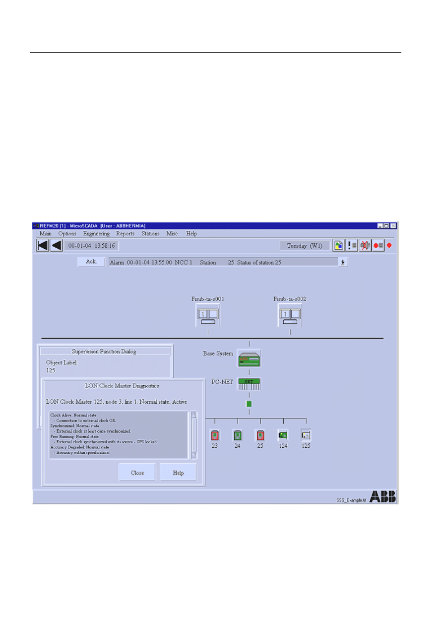
136
1MRS751880-MEN
LIB 500 Configuration Manual
LIB 500
8. System self supervision Configuration Guide
The system supervision picture, Event and Alarm List are described in the
following.
8.2.9.1.
System Supervision picture
The HSI of the LIB 500 System Self Supervision mainly consists of various system
supervision picture functions installed on the system supervision picture. System
supervision picture functions can be installed and configured according to the
supervised system. Thus, each picture function represents a hardware or software
part included into running system. In this way the state of each picture function
represents the supervision information from actual process devices and software
components. The current state of each picture function is presented, when
components described in the above chapters are involved into data flow of System
Self Supervision. The state of the supervised system objects (i.e. normal or alarm
state) is represented by using the color indications as defined in the Section 8.5.2.
The following figure displays the system supervision picture.
)LJ 6\VWHPVXSHUYLVLRQSLFWXUH
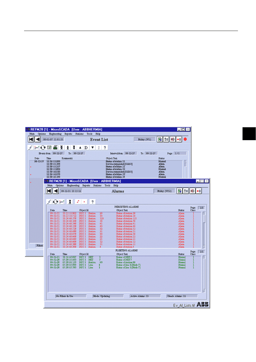
1MRS751880-MEN
LIB 500
137
LIB 500 Configuration Manual
Configuration Guide
8. System self supervision
8
8.2.9.2.
Event and alarm list
Each monitored object may include several events and/or alarms generated to the
Event and the Alarm List. Events and alarms of each supervised object are generated
according to the event filtering specified during the configuration phase of
Supervision Base. More information about configuration of event filtering file can
be found from the Section 8.4.
Please note that in a case of alarm, both group and informative alarm is being
generated to the Alarm List. Group alarm indicates the current state of the
supervised object and it is set to the normal value as the alarm is lowered (i.e. the
supervised object receives the normalised event). Informative alarm indicates the
cause of the alarm (e.g. Device suspended [13371]) and is set to the normal value as
the alarm is being acknowledged.
The following figure displays both an Event and an Alarm list with system
supervision events and alarms.
)LJ $ODUP/LVWZLWKV\VWHPVXSHUYLVLRQDODUPV

138
1MRS751880-MEN
LIB 500 Configuration Manual
LIB 500
8. System self supervision Configuration Guide
8.3.
Supervision base general
8.3.1.
Installation
The Supervision Base functionality is installed to the system in one of the following
ways:
• Installation of SSS Backbone functionality is being enabled from the Tools menu
of the System Configuration Tool. The SSS Backbone functionality will be
installed according to the system configuration.
• The SSS Backbone functionality will be installed as the supervision monitoring
objects related to the Supervision Monitoring part is being installed to the system
supervision picture. The SSS Backbone functionality is then be installed only for
that specific object at the time.
8.3.1.1.
Environmental requirements
In order to obtain have full operatibility, the product package LIB 500 System Self
Supervision sets the following environmental requirements:
• System Self Supervision routing switch is defined and enabled in
SYS_BASCON.COM (System Variable -attribute)
#CREATE SYS:B = LIST(-
- ;MS-STOOL Settings
PH = %l_Standard_Paths,-
SV = (0,-
list(t_System_Configuration_File = "sys_/SysConf.ini",-
b_Conf_Mech_In_Use = TRUE,-
EB666B0HFKB,QB8VH 758(
t_Version = "8.4.2")),-
• Operating System events are enabled in SYS_BASCON.COM (Enable Operating
System Event Handler and Operating System Event Handler Filter -attributes)
#CREATE SYS:B = LIST(-
- ;Operating System events
OE = 1,- ;1=Enabled, 0=Disabled
OT = (Bit_Mask(0,1,2,3,4),- ;Application events
Bit_Mask(0,1,2,3,4),- ;System events
Bit_Mask(0,1,2,3,4)),- ;Security events
- ;Bit 0 = ERROR
- ;Bit 1 = WARNING
- ;Bit 2 = INFORMATION
- ;Bit 3 = AUDIT_SUCCESS
- ;Bit 4 = AUDIT_FAILURE
• The number of parallel queues used in MicroSCADA application has to be at
least 4 (Parallel Queues and Queue Dedication -attributes in
SYS_BASCON.COM)
#CREATE APL:V = LIST(-
- ;Parallel queues and queue dedication
PQ = 4,- ;Number of parallel queues
QD = (1,1,1,1),- ;Parallel queue dedication
• System and Operating System events are enabled in MicroSCADA application
(System Event Enabled -attribute in SYS_BASCON.COM)

1MRS751880-MEN
LIB 500
139
LIB 500 Configuration Manual
Configuration Guide
8. System self supervision
8
#CREATE APL:V = LIST(-
- ;System Events & Operating System Events
EE = 1,- ; 1=Enabled, 0=Disabled
8.3.2.
Preliminary work
8.3.2.1.
System configuration
Installation and configuring of the communication related parts has to be done either
by use of the System Configuration Tool (PC-NET) or by use of the standard base
system configuration file, SYS_BASCON.COM (DCP-NET, MFL), and the NET
programs stored in the folder SYS/ACTIVE_/SYS. Event channels and command
procedures are also used for system configuration.
8.3.2.2.
The object identification in the database
General
The LIB5xx 4.0.3 supports partitioning of the Object Identification (OI) attribute
into five (5) identification fields. If less than five fields will be used, the unused
fields have to be the last ones i.e. the fifth field, the fourth field, etc. By default, only
three (3) fields will be used:
Table 8.3.2.2-1
The five (5) identification fields of the Object Identification
(OI) attribute
The sum of the field lengths should be equal or less than 30 characters.
The hierarchical structure has to be always maintained while reconfiguring the OI-
attribute. The first field defines the biggest group, the second field is a subgroup of
the biggest group and so on. System Self Supervision will require substation and bay
field in order to work properly.
If the utilisation of the OI-attribute needs to be modified due to different customer
requirements, the OI-attribute has to be changed before starting the creation of the
application database, i.e. there should not be any process objects in the process
object database. The configuration can be done in the SYS_BASCON.COM file.
Field
Default length
Range
Station name
10 characters (9 characters + 1
space)
2 .. 28
Bay name
15 characters (14 characters +
1 space)
2 .. 28
Device/apparatus name
5 characters
0, 2 .. 26 (0 = not in use)
Not specified
0
0, 2 .. 24 (0 = not in use)
Not specified
0
0 .. 22 (0 = not in use)

140
1MRS751880-MEN
LIB 500 Configuration Manual
LIB 500
8. System self supervision Configuration Guide
Usage of the OI -attribute in System Self Supervision
Table 8.3.2.2-2
In the System Self Supervision usage of the OI-attribute is
defined with the following way:
If the Device/apparatus name field is not defined, then the bay name field will be
constructed from the monitoring object name and number in the System Self
Supervision, e.g. Station 21.
8.3.2.3.
The naming convention of the database
The naming convention of the database used as default in the System Self
Supervision is described in detail in the Section 8.3.4.7.
8.3.2.4.
Application and monitor language
If some other language than English is used in the signal texts Object Text (OX) -
attribute, it is necessary to define this local language at least for the user who is doing
the application engineering. It is also very important that the translation of all signal
texts has already been performed by the Text Translation Tool or by other means.
Please refer to Section 8.3.4.2 and Section 8.4 for further details.
8.3.3.
Configuration
8.3.3.1.
Configuration with system configuration tool
General
In the System Configuration Tool, the functionality of System Self Supervision can
be enabled and disabled by using appropriate menu item in the menu bar. When
System Self Supervision functionality is enabled in the System Configuration Tool,
it checks that the appropriate command procedures, event channels and time
channels are included into the process database of current application for
Supervision Routing Interpreter. If this is not the case, the System Configuration
Tool executes the installation of these application objects.
When configuration data is saved in the System Configuration Tool by using
appropriate menu item and System Self Supervision functionality is enabled, all the
application objects are created to the process database of current application
simultaneously. During save operation it is also possible to remove previously
included configuration objects from the process database by enabling appropriate
dialog items in System Configuration Tool.
Field
Purpose
Comment
Station name
System name (SYS:BCX), e.g.
NCC 1
The System name can be
defined in the Application
Settings picture
Bay name
Monitoring object name, e.g.
Station
Monitoring object names as
default: OS, SYS, APL,
Node, NET, Line, Station,
SLCM and Printer
Device/apparatus name
Monitoring object number
-
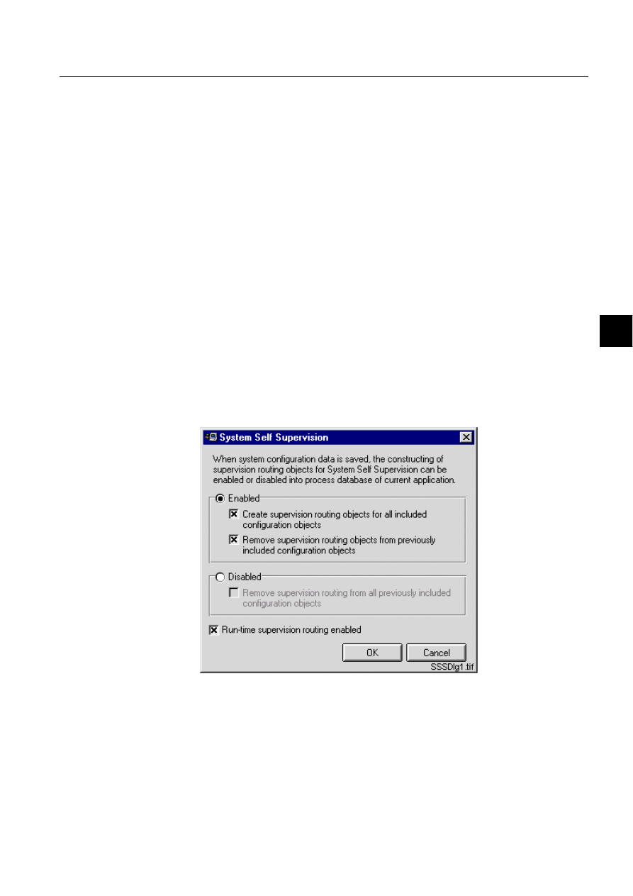
1MRS751880-MEN
LIB 500
141
LIB 500 Configuration Manual
Configuration Guide
8. System self supervision
8
User interface
6\VWHP6HOI6XSHUYLVLRQ6HWWLQJV
The behaviour of System Self Supervision functionality in the System Configuration
Tool is defined in the dialog below, see (see Fig. 8.3.3.1.-1). This dialog is accessed
from the menu bar Settings - System Self Supervision. System Self Supervision is
always dedicated into certain MicroSCADA application, i.e. into sets of command
procedures, event channels, time channels, process objects, data objects and
parameter files. System Self Supervision functionality can be enabled in the
MicroSCADA application, either installing the first picture function from the LIB
500 System Self Supervision 2.x package or by selecting the enabled state from the
dialog below.
When the System Self Supervision functionality is enabled in MicroSCADA
application, the System Configuration Tool doesn’t create supervision routing
objects for all included configuration objects as a default. This means that user has
to select the appropriate selection from the dialog. To be able to remove the
supervision routing objects from previously included configuration objects requires
also setting of that dialog item in the System Self Supervision dialog.
If no picture function is installed from the LIB 500 System Self Supervision 2.x
package, when System Configuration Tool is accessed for the first time and this
dialog is opened, the System Self Supervision is in disabled state. Also as a default
to remove supervision routing from all previously included configuration objects
requires setting of that dialog item in the System Self Supervision dialog.
)LJ 6\VWHP6HOI6XSHUYLVLRQGLDORJ
If this dialog is accessed, when previous SYS_BASCON.COM template is being
used, the following dialog is displayed to the user, see (see Fig. 8.3.3.1.-2). This is
because, for the System Self Supervision routing the base system object definition
(SYS:BSV) has to include a new attribute called B_SSS_MECH_IN_USE on its
second element. An example of this attribute can be found from the new template
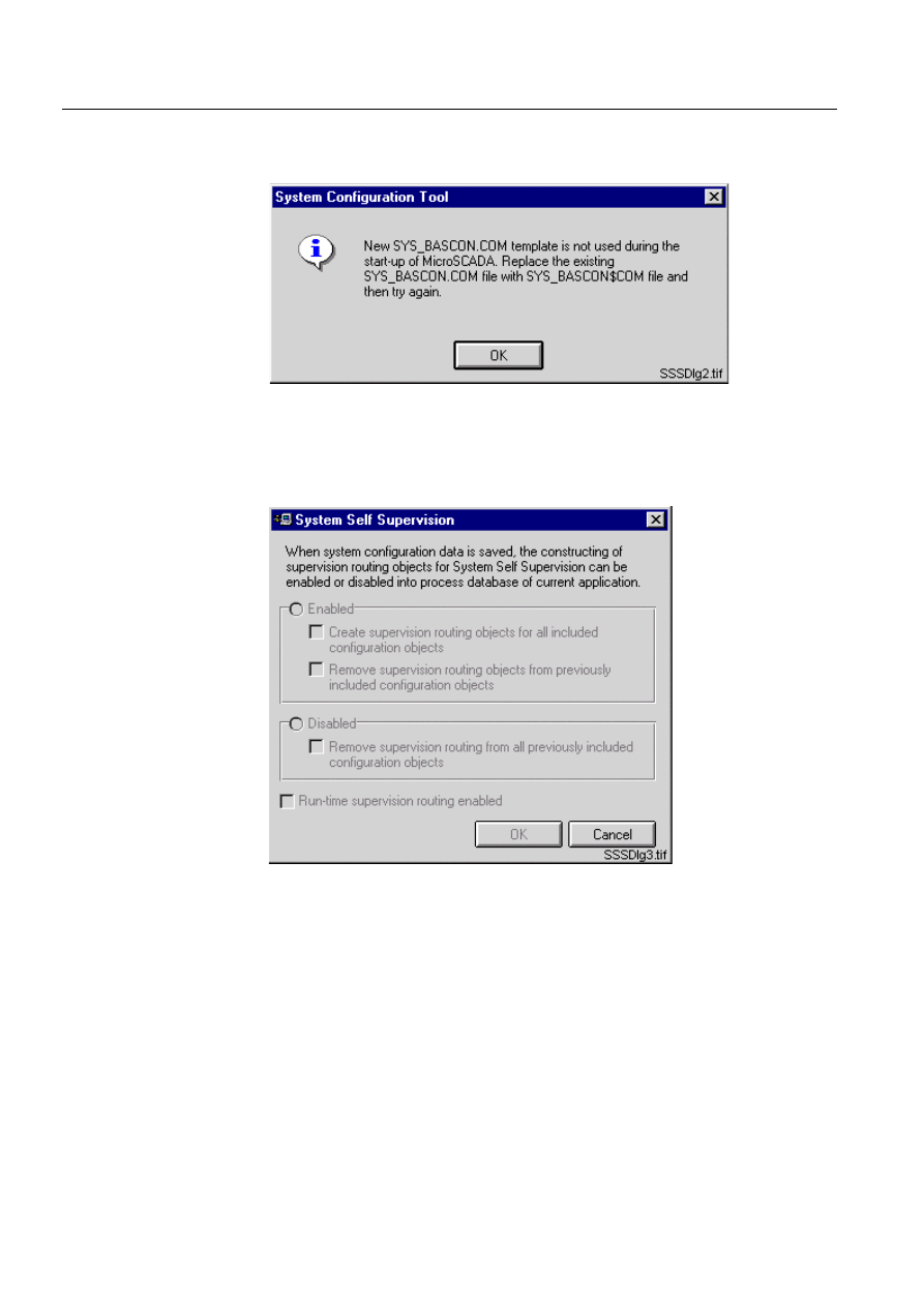
142
1MRS751880-MEN
LIB 500 Configuration Manual
LIB 500
8. System self supervision Configuration Guide
delivered together with MicroSCADA installation in the file
SYS_BASCON$COM. Refer to the Section 8.3.1.1 for detailed information.
)LJ 2OG6<6B%$6&21&20XVHG
When old SYS_BASCON.COM is used during start-up of MicroSCADA, the
System Self Supervision dialog is disabled for defining the functionality, see (see
Fig. 8.3.3.1.-3).
)LJ 'LVDEOHG6\VWHP6HOI6XSHUYLVLRQGLDORJ
If new SYS_BASCON.COM template is being used during start-up of
MicroSCADA it is possible to stop and start the run-time supervision routing in
application. Stopping and starting is occurred by using appropriate dialog item in the
bottom of System Self Supervision dialog. If run-time supervision routing is active,
and dialog item is unset, the following dialog is displayed to the user, see (see
Fig. 8.3.3.1.-4). Clicking of Yes, stops the run-time supervision routing. Clicking of
No, cancels the stop operation for run-time supervision routing.
When supervision routing is stopped, all the command procedures, which are being
used for collecting the supervision information from the system, are set into inactive
state. It means that supervision information is not anymore updated into process
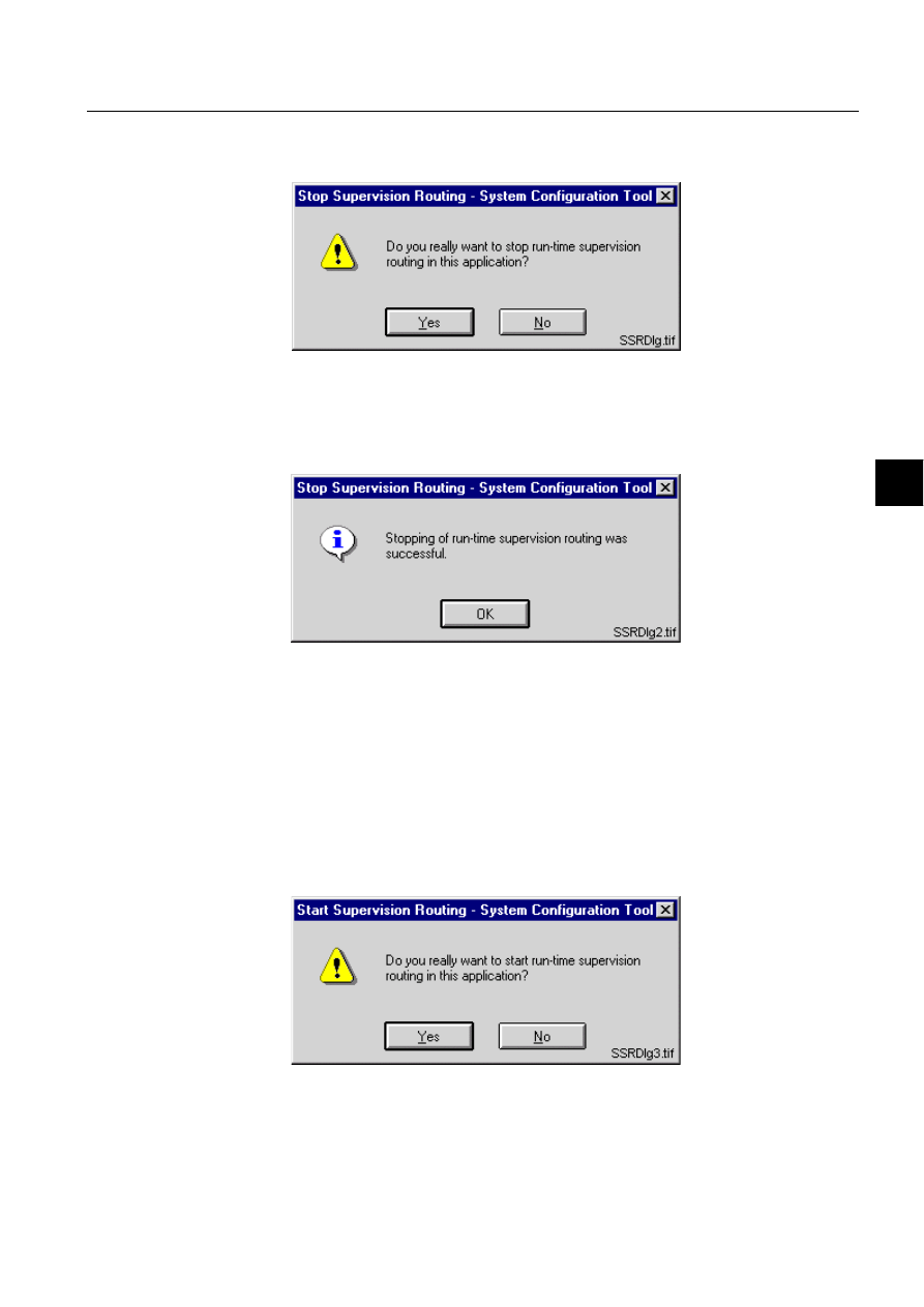
1MRS751880-MEN
LIB 500
143
LIB 500 Configuration Manual
Configuration Guide
8. System self supervision
8
database, and the latest values, which were previously received into process
database are being used for displaying the current state of the system.
)LJ 6WRS6XSHUYLVLRQ5RXWLQJGLDORJ
If stopping of run-time supervision was successful, the following dialog is displayed
to the user, (see Fig. 8.3.3.1.-5). If not, the dialog with text "Couldn’t stop the run-
time supervision routing" is displayed to the user together with status code and text.
)LJ 6XFFHVVIXO6WRS6XSHUYLVLRQ5RXWLQJGLDORJ
If run-time supervision routing is inactive, and dialog item is set, the following
dialog is displayed to the user, see (see Fig. 8.3.3.1.-6). Clicking of Yes, starts the
run-time supervision routing. Clicking of No, cancels the start operation for run-time
supervision routing.
When supervision routing is started, all the command procedures, which have been
inactive to collect the supervision information from the system, are set into active
state again. It means that supervision information is updated into process database,
and the latest values in process database are received as event-based or time based
from the supervised objects.
)LJ 6WDUW6XSHUYLVLRQ5RXWLQJGLDORJ

144
1MRS751880-MEN
LIB 500 Configuration Manual
LIB 500
8. System self supervision Configuration Guide
If starting of run-time supervision was successful, the following dialog is displayed
to the user, (see Fig. 8.3.3.1.-7). If not, the dialog with text "Couldn’t start the run-
time supervision routing" is displayed to the user together with status code and text.
)LJ 6XFFHVVIXO6WDUW6XSHUYLVLRQ5RXWLQJGLDORJ
6XSHUYLVLRQ/RJ
The System Configuration Tool includes also access to Supervision Log, see (see
Fig. 8.3.3.1.-8). This dialog is accessed from the menu bar Tools – System Self
Supervision Log. The Supervision Log displays all the different events in
MicroSCADA and Microsoft Windows NT Operating System by using views to
these different log types. Different log types are:
• Common System Messages
• Unknown Process Objects
• System Events from Operating System
• Security Events from Operating System
• Application Events from Operating System.
The log type to be shown can be selected from the Log menu and selecting the
appropriate log type from the menu items. For the events shown in the view there is
possibility to set the different filter condition, e.g. events from certain station
number.
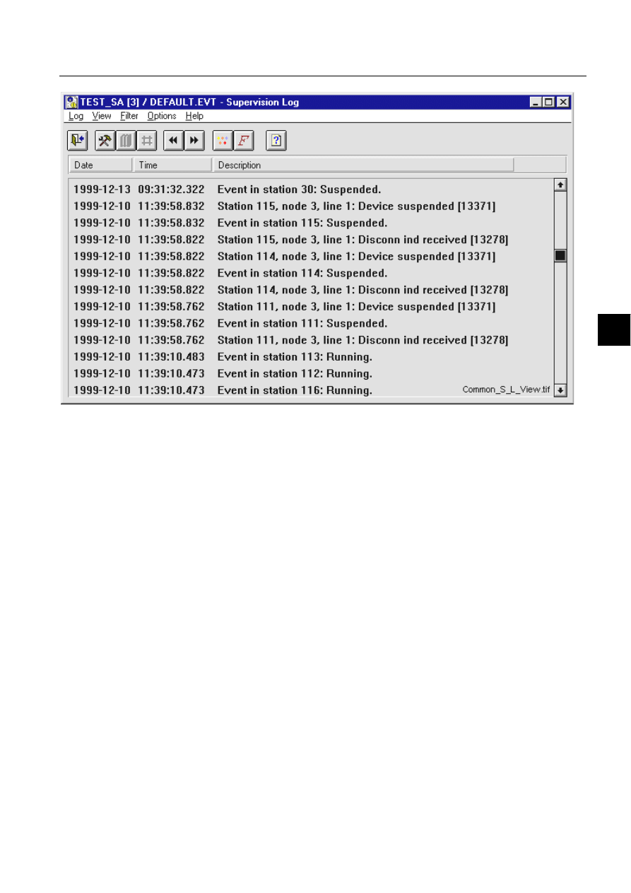
1MRS751880-MEN
LIB 500
145
LIB 500 Configuration Manual
Configuration Guide
8. System self supervision
8
)LJ 6XSHUYLVLRQ/RJGLDORJ
8.3.3.2.
Configuration of NET, NET line and LMK stations
In order to get all the diagnostic data concerning the NETs and the LMK stations of
communication system, the Diagnostic Interval (DI) -attributes for both of these
objects has to be set higher than value 0. In addition, if there is a printer line in
question, the Output Synchronization (OS) -attribute of this line has to be equal to
3, or in case of LON line used with a LON Clock Master (SLCM), the Link Type
(LK) –attribute of this line has to be equal to 0.
For the NETs this attribute determines the time in seconds between diagnostic
messages from the MicroSCADA base system to the NET. A failed diagnostic
message generates an event node connection lost and successful diagnostic message
generates an event node connection found. These both events are generated through
predefined event SYS_EVENT. As default, value of this attribute for NET
communication system object is set to 0. This value represents that no diagnostic
messages are being sent.
In case of the LMK station this attribute determines the time in seconds between the
periodical polls of the node status of the physical device. The status poll is used for
checking that the connection is alive. A failed status poll suspends the station. As
default, value of this attribute for station communication system object is set to 0.
This value represents that no connection check polling is being used.
In case of the NET line for printer, the Output Synchronization (OS) -attribute has
to be set to 3 (XON/XOFF with DCD supervision) in order to get all the diagnostic
data concerning the printer connected to a communication unit. The Output
Synchronization attribute applies to printer lines only and it defines the flow control

146
1MRS751880-MEN
LIB 500 Configuration Manual
LIB 500
8. System self supervision Configuration Guide
principle used by the printer. Please note that the cable wiring of the printer
connection differs depending on the value of Output Synchronization attribute, see
the Installation Manual for further details.
If the LON Clock Master (SLCM) is used in the NET line for LON communication
in order to synchronize other devices according to time information received from
the clock reference device (e.g. GPS), the Link Type attribute has to be set to 0 (no
clock synchronization). As default, value of this attribute is set to 3 (send LSG and
minute pulse).
8.3.3.3.
Configuration of LON clock master (SLCM)
General
The LON Clock Master (SLCM) option card is designed for use within the LON Star
Coupler, RER 111 unit. The SLCM option card is a LON node that interfaces to a
clock reference device. The clock reference interface is in the form of a 9 pin D-type
female connector including 3-wire RS-232 connection and minute/second pulse
signal.
The SLCM option card, when integrated within the RER 111 unit, provides a
connection from a time reference to the
LON
W
ORKS
network. SLCM option card
includes an internal clock and an application program, which uses the internal clock
to generate various kinds of synchronization messages and signals in order to
synchronize other devices on the LonWorks network.
To receive event-based device diagnostics from LON Clock Master to
MicroSCADA, the LON network variable configuration must be done.
Please note that the LIB 500 System Self Supervision functionality supports only
SLCM option cards of revision C (or later). Revision of the SLCM option card can
be checked from the printed circuit board (PCB) or refer to the Technical Reference
Manual of SLCM Option Card, 1MRS 750985-MUM.
Configuration of Network Variables
During the configuration the network variables of one LON Clock Master are
logically connected, i.e. bounded, to network variables in other LON nodes.
During binding of the output network variables of the LON Clock Master are
connected to the input network variables in other nodes. Input network variables of
the LON Clock Master are bound to output network variables in other nodes.
The connections between network variables are done with the help of the network
variable configuration table and address table. The network variable configuration
table includes the network selector values, which are used as system-wide addresses
of the network variables. The address table of a node contains the addresses of all
the other nodes to which the node is going to send messages. If messages are sent to
a group of nodes or if they are broadcasted to the network then the address table also
contains group address and broadcast address definitions.
Primary and secondary SLCMs
The SLCMs included into system can be divided into primary and secondary
SLCMs. Primary are the SLCMs, which are either active or redundant and directly
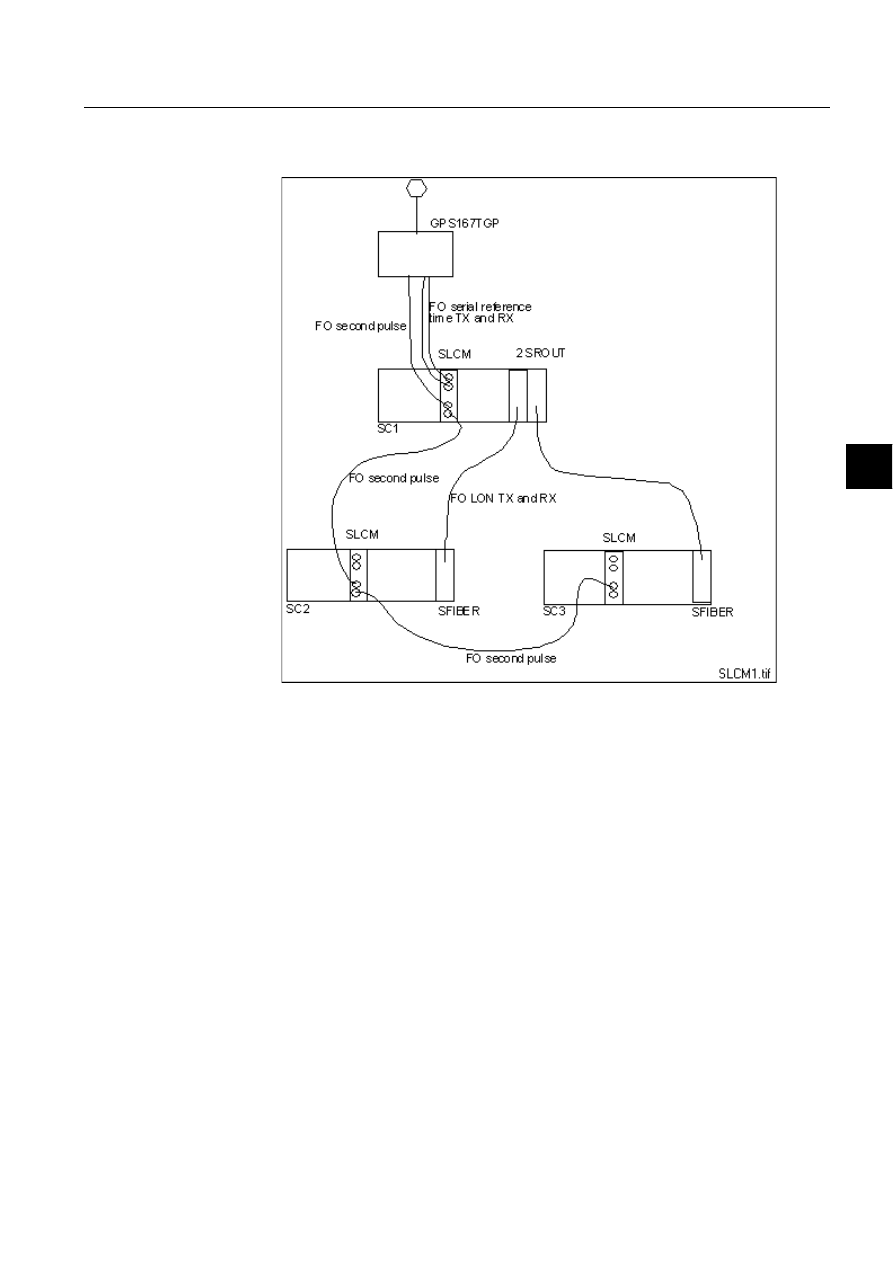
1MRS751880-MEN
LIB 500
147
LIB 500 Configuration Manual
Configuration Guide
8. System self supervision
8
connected to the GPS device through serial connection. Whereas secondary are
SLCMs connected to the primary SLCMs through fibre optic.
)LJ 6\VWHPZLWKSULPDU\DQGVHFRQGDU\6/&0V5HIHUHQFHWLPHLV
GLVWULEXWHGRQ/21YLDURXWHUVXVLQJWKHSULPDU\6/&0
FRQQHFWHGWRFORFNUHIHUHQFHLQPDVWHUPDVWHUPRGH
If supervision diagnostics is required also from the secondary SLCMs, additional
system configuration is defined for each secondary SLCM. This means that for the
secondary SLCM, the NV index 7 nv_invalid_ref should become configured. The
configuration consists of definition of NV entry into SLCM stations signal
configuration with NV index 7, an entry with specified selector value and NV index
7 into Network Variable configuration of that same LON line and creation of process
object into process database to receive the states of the three bits (0, 1 and 2) to be
supervised. Because the creation of NV indices 17 and 19 is done automatically by
the System Configuration Tool for primary SLCM during save operation, it is
preferred to investigate these definitions done by the System Configuration Tool.
Information how to create these definitions is similar to the NV indices 17 and 19.
Please note that supervision of secondary SLCMs is not supported by default in the
LIB 500 System Self Supervision functionality, neither in the Supervision Base or
in the Supervision Monitoring part.

148
1MRS751880-MEN
LIB 500 Configuration Manual
LIB 500
8. System self supervision Configuration Guide
Example for single SLCM
When System Configuration Tool includes LON Clock Master in configuration
data, the network variables for event-based device diagnostics are automatically
constructed during save operation, when System Self Supervision functionality was
enabled in tool. After that there is always need to change the default selector values
proposed by the System Configuration Tool in the LON line property of
configuration data (default selectors: 3FEF and 3FEE) according to neuron chip
network variable configuration in LON Clock Master.
The neuron chip network variable configuration in LON Clock Master can be
defined by using LON Network Tool or System Configuration Tool in online mode.
Table 8.3.3.3-1
The neuron chip network variable configuration
1RWH The direction is interpreted from the LON Clock Master neuron chip point of
view.
*
Bounded network variable range for selector values: 0000H – 2FFFH, also
Diagnostic Interval (DI) attribute value of communication system object for
SLCM must be higher than 0 second. When PC-NET has been started, the
initial state for network variables configured into LON line with selector
values inside bounded network variable range are read through LON
management NV Poll command. If also Consistency Check Time (CT)
attribute value of communication system object for SLCM is higher than 0
minute, the PC-NET also executes the NV Poll command between defined CT
minute value interval.
Network variable name NV_CLOCK_STATUS_1 with index 17 is the network
variable for GPS diagnostics from active SLCM and it is being sent, whenever the
state of reference time device changes and also during take over situations. Network
variable name NV_CLOCK_STATUS_2 with index 19 is sent from the redundant
SLCM, whenever the state of the reference time device changes. All these network
variables are of type SNVT_state. Note that in the case of single SLCM system also
the network variable configuration for redundant SLCM diagnostics (index 19) is
being constructed. System Configuration Tool reserves this network variable index
to be used in the future, when system is possible extended to include redundant
SLCM pair.
MicroSCADA LON line network variable configuration by using System
Configuration Tool (done automatically during save, only selector values require
updating according to above table).
Table 8.3.3.3-2
MicroSCADA LON line network variable configuration by
using System Configuration Tool
NV Name
NV Index
Direction
Selector, SLCM *
NV_CLOCK_STATUS_1
17
Output NV
1111 (hex)
NV_CLOCK_STATUS_2
19
Output NV
1113 (hex)
Purpose
NV Index
Direction
Selector, LON line
Active status, SLCM
17
Input NV
1111 (hex)
Redundant status, SLCM
19
Input NV
1113 (hex)
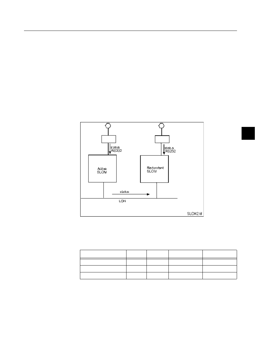
1MRS751880-MEN
LIB 500
149
LIB 500 Configuration Manual
Configuration Guide
8. System self supervision
8
1RWH The direction is interpreted from the MicroSCADA point of view.
In the LonTalk protocol terminology an input network variable is a variable, which
is received by the node and an output network variable is a variable, which is send
from the node.
Example for redundant SLCM pair
Two LON Clock Masters with node numbers 1 and 2 were used. When System
Configuration Tool included these two LON Clock Masters in configuration data,
the network variables for event-based device diagnostics are automatically
constructed during save operation, when System Self Supervision functionality was
enabled in tool. After that there is always need to change the default selector values
proposed by the System Configuration Tool in the LON line property of
configuration data (default selectors: 3FEF and 3FEE) according to neuron chip
network variable configuration in LON Clock Master.
)LJ 6\VWHPZLWKUHGXQGDQW6/&0SDLU
The neuron chip network variable configuration in LON Clock Master can be
defined by using LON Network Tool or System Configuration Tool in online mode.
Table 8.3.3.3-3
The neuron chip network variable configuration
1RWH The direction is interpreted from the LON Clock Master neuron chip point of
view.
*
Bounded network variable range for selector values: 0000H – 2FFFH, also
Diagnostic Interval (DI) attribute value of communication system object for
SLCM must be higher than 0 second. When PC-NET has been started, the
NV Name
NV Index
Direction
Selector, SLCM 1 Selector, SLCM 2
NV_CLOCK_STATUS_1
17
Output NV
1111 (hex)
2111 (hex)
NV_CLOCK_STATUS_1
18
Input NV
2111 (hex)
1111 (hex)
NV_CLOCK_STATUS_2
19
Output NV
1113 (hex)
2113 (hex)

150
1MRS751880-MEN
LIB 500 Configuration Manual
LIB 500
8. System self supervision Configuration Guide
initial state for network variables configured into LON line with selector
values inside bounded network variable range are read through LON
management NV Poll command. If also Consistency Check Time (CT)
attribute value of communication system object for SLCM is higher than 0
minute, the PC-NET also executes the NV Poll command between defined CT
minute value interval.
Network variable name NV_CLOCK_STATUS_1 with index 17 is the network
variable for GPS diagnostics from active SLCM and it is being sent, whenever the
state of reference time device changes and also during take over situations. Network
variable name NV_CLOCK_STATUS_1 with index 18 is updated, when redundant
SLCM receives status of active SLCM. Network variable name
NV_CLOCK_STATUS_2 with index 19 is sent from the redundant SLCM,
whenever the state of the reference time device changes. All these network variables
are of type SNVT_state.
MicroSCADA LON line network variable configuration by using System
Configuration Tool (done automatically during save, only selector values require
updating according to above table, NV Index 18 is not included to MicroSCADA
because it is used for horizontal communication between two SLCM).
Table 8.3.3.3-4
MicroSCADA LON line network variable configuration by
using System Configuration Tool
1RWH The direction is interpreted from the MicroSCADA point of view.
8.3.4.
Engineering information
8.3.4.1.
The structure of the supervision base
This chapter describes the structure of the Supervision Base. All files, form pictures
and database objects are included. The SSS Backbone related files will be located
under System Tools in /STOOL/SUPERV folder. The following directory structure
applies for the SSS Backbone functions:
• The /STOOL/SUPERV folder contains files for storing the configuration data and
event filtering information (default), files containing the source code for
command procedures and files related to System Configuration Manager services
• The /STOOL/SUPERV/LANG_TEXTS folder contains language dependent texts
needed by the SSS Backbone functionality
In the application level, following directory structure applies for the System Self
Supervision functions:
• The /SUPERV folder contains all the application specific files related to the
System Self Supervision functions (e.g. initialisation and log files)
Purpose
NV Index
Direction
Selector, LON line
Active status, SLCM 1
17
Input NV
1111 (hex)
Redundant status, SLCM 1
19
Input NV
1113 (hex)
Active status, SLCM 2
117
Input NV
2111 (hex)
Redundant status, SLCM 2
119
Input NV
2113 (hex)
1MRS751880-MEN
LIB 500
151
LIB 500 Configuration Manual
Configuration Guide
8. System self supervision
8
8.3.4.2.
Language text files
The following Text Translation Tool compatible text files are used by the SSS
Backbone. The path is /STOOL/SUPERV/LANG_TEXTS
Table 8.3.4.2-1
The Text Translation Tool compatible text files used by the
SSS Backbone
The SSS Backbone text file consists of unique text identifiers together with a
language dependent text string. The language stored into text file can be found out
from the section name. The contents of this text file can be modified by using the
Text Translation Tool, see the Section 8.4.3 for further details.
The text identifiers are used in the System Self Supervision in the following
occasions:
• As the application objects are created to the report database (i.e. language
dependent comment texts)
• As the process objects are created to the report database (i.e. language dependent
signal texts, the object identification and the object text)
• As the log events are shown in the Supervision Log
8.3.4.3.
Initialisation files
The following initialisation files are used by the System Self Supervision. The path
is /STOOL/SUPERV/
Default initialisation files are copied under the application folder /SUPERV as the
System Self Supervision functionality is applied
Table 8.3.4.3-1
The initialisation files used by the System Self Supervision
The main function of initialisation files is to include configuration data concerning
the objects to be supervised in the system and event filtering data concerning the
events to be notified in supervision routing.
The data stored into these files is utilised actively during supervision routing through
Supervision Routing Interpreter via System Configuration Manager services.
Initialisation file for configuration data is updated during installation of the System
Text file
Functionality
SSSTexts.ini
Text file for the database creation and for log event
presentations of the SSS Backbone functionality
Initialisation file
Functionality
SSSCONF.INI
Initialisation file for the configuration data of the System Self
Supervision.
SSSEVENT.INI
Initialisation file for the event and alarm handling of the System
Self Supervision.
SSSFILTER.INI
Initialisation file for the event filtering data of the System Self
Supervision.

152
1MRS751880-MEN
LIB 500 Configuration Manual
LIB 500
8. System self supervision Configuration Guide
Self Supervision functionality (as the SSS Backbone functionality is installed with
the System Configuration Tool or the first picture function is being installed to the
system supervision picture).
Initialisation file for event filtering data has the default settings after installation of
the System Self Supervision. Default event filtering file includes references to
communication units, communication unit lines, stations, LON Clock Masters,
printers, predefined and specified events, i.e. references to the supported objects in
the System Self Supervision. These default settings can be modified as project-
specific by using some text editor, for example SCIL Editor. Refer to the Section
8.4.2 for further details.
8.3.4.4.
Configuration files
The following configuration file is used by the System Self Supervision. The path is
/STOOL/SUPERV/
Table 8.3.4.4-1
The configuration file used by the System Self Supervision
The configuration file contains the configuration data for the general parameters of
the System Self Supervision. In the specified file the following settings are defined:
• File path for System Self Supervision 2.x under application
• File path and name for the configuration file
• File path and name for the filter file
• File path and name for the event file
• File path and name for the text file
• Interval for application status checking from external base system (in case of
external application or a hot-stand-by system)
• Interval for communication unit status checking
• Default timeout length used within System Self Supervision 2.x
• Enable/Disable events in station (i.e. APL_EVENT)
• Enable/Disable system messages in station
• Enable/Disable activation of the log file events
• Enable/Disable activation of the events
• Enable/Disable activation of the alarms
• Default length of the log file
• Default separator used in the log file
If the application specific modifications to the general parameters are needed, the
configuration file can be copied under the application folder /SUPERV and do the
modifications there. Refer to the Section 8.4.4 for further details.
Configuration file
Functionality
SSS_SETUP.SCL
Contains the configuration data for the general parameters of
the System Self Supervision.
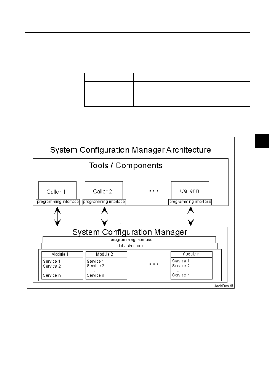
1MRS751880-MEN
LIB 500
153
LIB 500 Configuration Manual
Configuration Guide
8. System self supervision
8
8.3.4.5.
System configuration manager files
The following System Configuration Manager files are used by the System Self
Supervision. The path is /STOOL/SUPERV/
Table 8.3.4.5-1
The System Configuration Manager files used by the System
Self Supervision
In order to maintain the common interface between the system configuration and the
system supervision functions, a new system configuration service provider, System
Configuration Manager is introduced.
)LJ $UFKLWHFWXUH'HVLJQRI6\VWHP&RQILJXUDWLRQ0DQDJHU
System Configuration Manager contains a collection of services, i.e. methods to be
provided for calling tools and components. During the System Self Supervision
engineering, the calling tool for these services may be either System Configuration
Tool or System Self Supervision picture functions during their installation of
Installation Tool and usage of Standard Configuration Tool both accessed from
Configuration file
Functionality
SSS_MGR.MOD
Contains the source code of the System Configuration Manager
services used in the System Self Supervision.
SSS_MGR2.MOD
Contains the source code of the System Configuration Manager
services used in the System Self Supervision.

154
1MRS751880-MEN
LIB 500 Configuration Manual
LIB 500
8. System self supervision Configuration Guide
Picture Editor. The services provided by the System Configuration Manager can be
utilized, when interacting with following components:
• Process objects
• Event channels
• Command procedures
• Time channels
• Data objects
• Handling of System Self Supervision initialization and event filtering files
• Constructing network variables bindings for LON Clock Master diagnostics
• Handling of log file information
• Retrieving of status messages
• Retrieving of base system object definitions
• Activation of System Self Supervision functionality
Before the services inside some module can be utilized, the System Configuration
Manager for that module need to be initialised. During initialisation the contents of
System Configuration Manager related module is constructed, i.e. the programming
interface, data structures and services inside that module are initialised for their
usage.
The services from some module can be utilized directly after initialisation of this
module. The services inside that module are accessed with the standard
programming interface independent from the module location, file name and
extension. With the standard programming interface the services from each module
can be retrieved with similar way. Because same programming interface is used the
possible changes which may occur to the module implementation inside System
Configuration Manager can be hidden from the calling tools and components.
When the services inside some module are not anymore needed, the System
Configuration Manager for that module need to be deleted from the calling tool.
During deletion the contents of specified module in System Configuration Manager
is cleared, i.e. the services inside that module are deleted from the run-time memory.
It is not possible to use anymore the services from that deleted module after deletion
without reinitialization. Services that have been loaded into context of calling tool,
become also deleted, when appropriate tool is closed.
Services provided by System Configuration Manager can be used, when an
initialization is done for the module to be utilized. During initialization the services
are stored to the run-time memory of MicroSCADA application. These services can
be accessed through standard programming interface either from command
procedures (Supervision Routing Interpreter) or Visual SCIL dialogs (System
Configuration Tool).
Each time, when some service is being utilized, a data structure is returned to the
calling tool. This data includes information about the status of service execution, and
possibly data item and descriptive text. In the case of successful service usage, the
status value equal to 0 is returned.
Also exceptions may occur during usage of these System Configuration Manager
services. When an exception is occurred, the returned data includes information
about the exception. Exceptions can be divided into two categories:

1MRS751880-MEN
LIB 500
155
LIB 500 Configuration Manual
Configuration Guide
8. System self supervision
8
1. Information cannot be found (element STATUS < 0, no data item and no
descriptive text)
2. Wrong usage of service or internal error of service (element STATUS > 0, no
data item and element DESCRIPTIVE_TEXT includes description of occurred
error)
If exception 1 occurs, no data item is included into the returned data at all. If
exception 2 occurs, no data item is included into the returned data, but the
descriptive text is included into returned data, which can be utilized in the calling
tool to describe the exception to the user.
8.3.4.6.
Other text files
The following text files are used by the System Self Supervision. The path is /
STOOL/SUPERV/
Table 8.3.4.6-1
The text files used by the System Self Supervision
8.3.4.7.
Process objects
In the System Self Supervision the process objects are created for the following
purposes:
• For receiving system messages from the communication units
• For indicating the state of the object
• For event and alarm handling
The process object groups are described more detailed below as well as default
naming and index conventions used in the database.
System message process objects
System message process objects (i.e. supervision routing points) are used for
receiving the status code information from the communication units. System
message process objects will be created according to the system configuration as the
SSS Backbone functionality is installed (or the specific picture function of the object
is being installed to the system supervision picture).
Configuration file
Functionality
SSS_APLINIT.SCL
Contains the source code for initialisation of local applications at
system start-up for the System Self Supervision.
SSS_APLOBJ.SCL
Contains the source code for creating command procedures,
time channels, data objects and event channels for System Self
Supervision.
SSS_INIT.SCL
Contains the source code for enabling/disabling the use of
command procedures for System Self Supervision.
SSS_LOGINIT.SCL
Contains the source code for initialisation of log files at system
start-up for the System Self Supervision.
SSS_REV.SCL
Contains the revision info for the System Self Supervision
SSS_UPDATE.SCL
Contains the source code for updating application objects after
revision update for the System Self Supervision.

156
1MRS751880-MEN
LIB 500 Configuration Manual
LIB 500
8. System self supervision Configuration Guide
Creation of the process objects is done by use of System Configuration Manager.
Naming and index conventions will be used for system message process objects as
default (if the object already exist, the current object will be used if usable). All the
references related to the created objects will be stored in the System Self Supervision
related initialization file.
Indication process objects
Indication process objects are used for indicating the current state of the object.
Indication process objects will be created according to the system configuration as
the SSS Backbone functionality is installed (or the specific picture function of the
object is being installed to the system supervision picture).
Creation of the process objects is done by use of System Configuration Manager.
Naming and index conventions will be used for indication process objects as default.
All the references related to the created objects will be stored in the System Self
Supervision related initialization file.
The current state of the supervised object is defined in the indication process object
by use of the value convention. Following state indications will apply for each
supervised object:
• Not in use (or object missing)
• Undefined (i.e. update blocked, invalid value, not sampled or not updated status)
• In use, no alarm
• In use, alarm unacknowledged
• In use, alarm acknowledged
Event and alarm process objects
Event and alarm process objects are used for event and alarm handling. Event and
alarm process objects will be created as the specified event occurs for the first time
in the system/application. Events that generate the activation of the event or/and
alarm process object are determined in the initialisation file for event filtering data.
Refer to the Section 8.3.4.3 and Section 8.4.4 for further details.
Creation of the process objects is done by the use of System Configuration Manager.
Naming and index conventions will be used for event/alarm process objects as
default. All the references related to the created objects will be stored in the System
Self Supervision related initialization file.

1MRS751880-MEN
LIB 500
157
LIB 500 Configuration Manual
Configuration Guide
8. System self supervision
8
Naming and index conventions
Table 8.3.4.7-1
Communication unit (NET) and base system nodes
<number> = object number with 4 digits
Table 8.3.4.7-2
Station and LON Clock Master (SLCM) objects
<number> = object number with 4 digits
Table 8.3.4.7-3
Printer objects
<number> = object number with 4 digits
Process Object
Type of Usage
Indexes
SYS_N<number>I
Communication
unit (NET)
10 – indication for communication unit (NET)
11 – indication for redundant frontend pair
21.. 28 – indication for communication unit lines
110 –routing point for communication unit (NET)
111 – routing point for redundant frontend pair
121..128 –routing points for communication unit
lines
Base System
10 – indication for global memory pool
supervision (BI)
SYS_N<number>E
Event objects
Indexes are created in ascending order
SYS_N<number>A
Alarm objects
Indexes are created in ascending order
Process Object
Type of Usage
Indexes
SYS_S<number>I
Station, e.g. SPA,
REX, IEC, DNP
10 – indication for station
110 – routing point for station
Station, RTU
10 – indication for station
11 – indication for RTU terminal status
110 – routing point for station
111 – routing point for RTU terminal status
LON Clock Master
(SLCM)
10 – indication for station communication
11 – indication for active SLCM
12 – indication for redundant SLCM
110 – routing point for station communication
111 – routing point for active SLCM
112 – routing point for redundant SLCM
SYS_S<number>E
Event objects
Indexes are created in the ascending order
SYS_S<number>A
Alarm objects
Indexes are created in the ascending order
Process Object
Type of Usage
Indexes
SYS_P<number>I
Printer
10 – indication for printer
110 –routing point for printer (only printers
connected to communication unit)
SYS_P<number>E
Event objects
Indexes are created in the ascending order
SYS_P<number>A
Alarm objects
Indexes are created in the ascending order

158
1MRS751880-MEN
LIB 500 Configuration Manual
LIB 500
8. System self supervision Configuration Guide
Table 8.3.4.7-4
Application objects
<number> = object number with 4 digits
Table 8.3.4.7-5
Operating System objects
<number> = object number with 4 digits (Base system node number)
8.3.4.8.
Scale objects
At first installation of the System Self Supervision, the scale 1_1 (linear 1:1 scale)
is created (if does not exist)
8.3.4.9.
Data bjects
At first installation of the System Self Supervision, the data object for the log file
counters is created (SYS_CNTR).
Each log files will contain maximum of 1000 events as default. If the number of
events is exceeded, a backup file is created and the collecting of events are started
again. The dedicated data object for the log file counters is allocated for counting the
cumulative number of events in each of the log file categories. Refer to the Section
8.4.4 for further details.
Process object
Type of usage
Indexes
SYS_A<number>I
Application (Local) 10 – indication for application state
11 –indication for application state (in case of a
hot-stand-by system, application in the external
base system node)
20 –indication for application shadowing phase
(in case of a hot-stand-by system)
21 –indication for application shadowing phase
(in case of a hot-stand-by system, application in
the external base system node)
30 –indication for local memory pools
[PICO_POOL, REPR_POOL and PRIN_POOL]
(BI)
40 –indication for local application queues
[Event channel queue, time channel, event,
parallel and delayed execution queues, process/
SCIL printouts] (BI)
Application
(External)
10 – indication for application state
11 – indication for application shadowing phase
SYS_A<number>E
Event objects
Indexes are created in the ascending order
SYS_A<number>A
Alarm objects
Indexes are created in the ascending order
Process object
Type of usage
Indexes
SYS_O<number>I
Operating System
10 – indication for System Events (BI)
11 – indication for Security Events (BI)
12 – indication for Application Events (BI)
SYS_O<number>E
Event objects
Indexes are created in the ascending order
SYS_O<number>A
Alarm objects
Indexes are created in the ascending order

1MRS751880-MEN
LIB 500
159
LIB 500 Configuration Manual
Configuration Guide
8. System self supervision
8
8.3.4.10.
Command procedures
At first installation of the System Self Supervision the following command
procedures are created: (The path for the source code files of the command
procedures is /STOOL/SUPERV/)
Table 8.3.4.10-1 Command procedures
8.3.4.11.
Time channels
At first installation of the System Self Supervision, the time channel for the
communication unit supervision is created (SYS_NETSR). Refer to the Section 8.4
for further details.
8.3.4.12.
Event channels
At first installation of the System Self Supervision the following event channels are
created:
Table 8.3.4.12-1 Event channels
Command
Procedure
Functionality
SYS_APLER
Command procedure for receiving APL_EVENT events
SYS_NETLMR
Command procedure for receiving system messages for
communication unit lines (NET lines)
SYS_NETMR
Command procedure for receiving system messages for
communication units (NET)
SYS_NETSR
Command procedure for communication unit supervision.
SYS_OSER
Command procedure for receiving OS_EVENT events
SYS_PRIMR
Command procedure for receiving system messages for printers
(printers that are connected to a communication unit)
SYS_SLCMR
Command procedure for receiving clock status information from the
LON Clock Master (SLCM)
SYS_SSSINI
Command procedure for initialisation of the System Self Supervision
at system start-up
SYS_SSSREV
Command procedure for revision info for the System Self Supervision
SYS_SSSRT
Command procedure for updating functionality of the System Self
Supervision at system start-up
SYS_STAMR
Command procedure for receiving system messages for stations
SYS_SYSER
Command procedure for receiving SYS_EVENT events
SYS_UPOER
Command procedure for receiving UNDEF_PROC events
Event Channel
Functionality
APL_EVENT
Event channel for receiving APL_EVENT events
OS_EVENT
Event channel for receiving OS_EVENT events
SYS_EVENT
Event channel for receiving SYS_EVENT events
SYS_NETLMR
Event channel for communication unit line system messages
SYS_NETMR
Event channel for communication unit system messages

160
1MRS751880-MEN
LIB 500 Configuration Manual
LIB 500
8. System self supervision Configuration Guide
8.3.4.13.
Format pictures and text files
The following format picture and text files are used by the System Self Supervision.
The path is /STOOL/SUPERV/
1RWHDefault format and text files are copied under application directory /FORM/
as the System Self Supervision functionality is applied.
Table 8.3.4.13-1 The format picture and text files used by the System Self
Supervision
8.3.4.14.
Visual SCIL object files
The following Visual SCIL object files are used by the System Self Supervision. The
path is /STOOL/SUPERV/
Table 8.3.4.14-1 The Visual SCIL object files used by the System Self
Supervision
8.4.
Project specific engineering
8.4.1.
General
The Supervision Base allows making of project specific changes into the system
supervision functionality. The project specific changes can be done to the following
functionality of Supervision Base:
• Event filtering
• Text translation
• General parameters.
Making of these changes to the Supervision Base functionality are described more
exactly in the following chapters.
SYS_PRIMR
Event channel for printer system messages
SYS_SLCMR
Event channel for LON Clock Master system messages
SYS_STAMR
Event channel for station system messages
UNDEF_PROC
Event channel for receiving UNDEF_PROC events
Event Channel
Functionality
File
Functionality
FORM4BSAI.PIC
Format picture for analog input
FORM4BSAI.TXT
Text file for the format picture of FORM4BSAI.PIC
FORM4BSBI.PIC
Format picture for binary input
FORM4BSBI.TXT
Text file for the format picture of FORM4BSBI.PIC
File
Functionality
SSSLVIEWER.VSO
Supervision Log dialog
SSSLVIEWER.INI
Initialisation file for the Supervision Log dialog

1MRS751880-MEN
LIB 500
161
LIB 500 Configuration Manual
Configuration Guide
8. System self supervision
8
8.4.2.
Event filtering
The events captured by the Supervision Base can be defined according to project
specific needs. By changing the default event filtering file, the System Self
Supervision can be configured to collect more data than the included into default
event filtering file delivered together with installation. By editing default event
filtering file, the System Self Supervision load to MicroSCADA system can be
increased or decreased. This file can be edited by using for example SCIL Editor.
Note! Project specific event filtering editing should occur to the file located in the
application’s SUPERV folder. If there is need however need to restore the default
event filtering file during configuration work, copy the SSSFILTER.INI from folder
/STOOL/SUPERV/ to the application’s SUPERV folder.
Event filtering file consists of information related to objects to be supervised by the
Supervision Base and for each supervised object also the specified list of events to
be captured. For each supervised object type, an own section name is included
according to Table 8.4.2-1, for example SYS_MSG_NET_PCNET for system
messages to PC-NET. Inside the same section name all the status codes are listed by
using unique key names, for example Status_10001. Also a comment text is
included to describe the purpose of this specified status code, for example
NETP_SYSTEM_INITIALIZED.An example of an event filtering file is shown in
Table 8.4.2-2.
For each specified event, the event flag information has been defined into a key
value, for example TRUE, TRUE, FALSE. These comma separated three flags
identify, whether log, event or alarm is being generated, when this specified event
occurs in the running system. The text string TRUE indicates that the appropriate
entry is generated, whereas in the case FALSE string, the System Self Supervision
does not generate appropriate entry from the event.
As default, all the events in event filtering file are collected into log files, and they
are shown in the Supervision Log Viewer. The most important status codes from the
supervision point of view are defined to be alarming in default event filtering file
delivered together with installation.
By defining the key values to TRUE for event or alarm definition it is possible to
include occurred event into Event or Alarm List. Event can be configured to be
included both into Event and Alarm List in event filtering file. For example, when
connection to station is lost in MicroSCADA system, the event is included also into
Event and Alarm List according to the default event filtering file.
Please note that the definitions of the key values affects also to the functionality of
Supervision Monitoring i.e. the current states of the picture functions in system
supervision picture are indicated according to the event filtering file.
Different format is being used for the key names depending on the object type to be
supervised. For supervision information received through system messages, the
prefix Status_ added status code number is used in the key name. If there is need to
add a new supervision event to be supervised by Supervision Base that means adding
of a new key name inside the section name for the supervised object type with event

162
1MRS751880-MEN
LIB 500 Configuration Manual
LIB 500
8. System self supervision Configuration Guide
flag information. See the example below, where the last key name Status_10010 is
added.
[SYS_MSG_NET_PCNET]
; These definitions apply to all PC-NET
Status_<status code>=<TRUE|FALSE>,<TRUE|FALSE>,<TRUE|FALSE>
; Common NET Status Codes
Status_10001=TRUE,TRUE,FALSE ;NETP_SYSTEM_INITIALIZED
Status_10002=TRUE,FALSE,FALSE ;NETP_IU_ATRIBUTE_WAS_EXPECTED
Status_10003=TRUE,FALSE,FALSE ;NETP_TIMEOUT_WHILE_WAITING_ACKNOWLEDGE
Status_10004=TRUE,FALSE,FALSE ;NETP_UNKNOWN_CONFIGURATION_OBJECT
Status_10005=TRUE,FALSE,FALSE ;NETP_UNKNOWN_SCM_FUNCTION
Status_10006=TRUE,TRUE,TRUE ;NETP_OUT_OF_MEMORY
Status_10007=TRUE,FALSE,FALSE ;NETP_CONFLICT_IN_PRECONFIGURATION
Status_10008=TRUE,FALSE,FALSE ;NETP_PROTOCOL_NOT_SUPPORTED
Status_10009=TRUE,FALSE,FALSE ;NETP_NAME_IS_LOGICAL_OR_UNDEFINED
6WDWXVB 758()$/6()$/6(1(:67$786&2'($''('
For supervision information received through events in stations and MicroSCADA
base system, the prefix Status_ added with snapshot variables SOURCE and
EVENT are used in key name. See an example of supervision event in default event
filtering file. More information about the SOURCE and EVENT can be found from
the System Objects manual.
[APL_EVENT]
; These definitions apply to all station types, e.g. REX, SPA etc.
Status_<source>_<event>=<TRUE|FALSE>,<TRUE|FALSE>,<TRUE|FALSE>
Status_UN_SUSPENDED=TRUE,TRUE,TRUE
Status_UN_RUNNING=TRUE,FALSE,FALSE
[SYS_EVENT]
; These definitions apply to all system events
Status_<source>_<event>=<TRUE|FALSE>,<TRUE|FALSE>,<TRUE|FALSE>
Status_NOD_LOST=TRUE,TRUE,TRUE
Status_NOD_FOUND=TRUE,FALSE,FALSE
Status_PRI_OUTPUT_LOST=TRUE,TRUE,TRUE
Status_APL_AS_COLD=TRUE,FALSE,FALSE
[OS_EVENT]
; These definitions apply to all operating system events
Status_<log>_<event>=<TRUE|FALSE>,<TRUE|FALSE>,<TRUE|FALSE>
Status_APPLICATION_ERROR=TRUE,FALSE,FALSE
Status_APPLICATION_WARNING=TRUE,FALSE,FALSE
For supervision information received through updated network variable information
from the LON Clock Master (SLCM), the key names for faulty bit numbers and
values are being used. See an example of this section from default event filtering file
below. More information about the diagnostics information received with
NV_CLOCK_STATUS_1 network variable type can be found from the
documentation delivered together with the LON Clock Master card.
[SYS_MSG_SLCM]
; These definitions apply to all LON Clock Masters
Faulty_Bit_Numbers=0,1,2,6
Faulty_Bit_Values=0,0,1,1
Status_Faulty=TRUE,TRUE,TRUE
Status_Normal=TRUE,FALSE,FALSE
The key value Faulty_Bit_Numbers specifies the bits to be supervised by the
Supervision Base. Whereas the key value Faulty_Bit_Values lists the bit states
(reset/set) in case of faulty status of LON Clock Master device. Whenever the first
one of the diagnostics bits receives faulty bit value from device, the LON Clock

1MRS751880-MEN
LIB 500
163
LIB 500 Configuration Manual
Configuration Guide
8. System self supervision
8
Master status is changed to faulty. The condition for normal status of LON Clock
Master is that all the diagnostics bits need to have normal bit value.
Since the NV_CLOCK_STATUS_1 network variable consists of multiple
diagnostics bits with different information, new bits can be added to be supervised.
For these new bits, the Supervision Base reuses the existing network variable
configuration included already for the standard supervision bits. If new project
specific bits are appended, also the contents of language dependent text file should
be modified to include new supervision event bit information into Supervision Log
Viewer.
In the following example is new project specific bit 4 added to be supervised by
Supervision Base related to the incoming change of winter or summer time of LON
Clock Master device. When the daylight saving time change is coming within an
hour, an event is stored into log file and changed status of LON Clock Master is
shown in Event List. In the case of LON Clock Master is informing from the coming
daylight saving time within an hour, the event appears also into Alarm List.
[SYS_MSG_SLCM]
; These definitions apply to all LON Clock Masters
Faulty_Bit_Numbers=0,1,2,4,6
Faulty_Bit_Values=0,0,1,1,1
Status_Faulty=TRUE,TRUE,TRUE
Status_Normal=TRUE,FALSE,FALSE
Table 8.4.2-1
System messages
Section Name
Functionality
SYS_MSG_PC_NET
System messages for PC-NET
SYS_MSG_DCP_NET
System messages for DCP-NET
SYS_MSG_NET_MFL
System messages for MFL
SYS_MSG_LINE_1
System messages for ANSI X3.28 Full Duplex of ACP line
SYS_MSG_LINE_4
System messages for ASCII protocol for printer line
SYS_MSG_LINE_7
System messages for RP-570 Master line
SYS_MSG_LINE_12 *
System messages for LCU500 line
SYS_MSG_LINE_14
System messages for SPA line
SYS_MSG_LINE_16
System messages for RP-570 Slave line
SYS_MSG_LINE_25 *
System messages for MODBUS RTU or ASCII Master line
SYS_MSG_LINE_27
System messages for LON line
SYS_MSG_LINE_29
System messages for IEC 101 Unbalanced Slave line
SYS_MSG_LINE_30
System messages for IEC 101 Balanced Slave line
SYS_MSG_LINE_31
System messages for IEC 101 Unbalanced Master line
SYS_MSG_LINE_32
System messages for IEC 101 Balanced Master line
SYS_MSG_LINE_33
System messages for IEC 103 Unbalanced Master line
SYS_MSG_LINE_35
System messages for DNP 3.0 Slave line
SYS_MSG_LINE_43
System messages for DNP 3.0 Master line
SYS_MSG_STA_SPA
System messages for SPA station
SYS_MSG_STA_REX
System messages for REX station
SYS_MSG_STA_LMK
System messages for LMK station

164
1MRS751880-MEN
LIB 500 Configuration Manual
LIB 500
8. System self supervision Configuration Guide
* These section names are commented in default event filtering file. If there is
project specific need to include these objects also to be supervised by the
Supervision Base, remove the semicolon characters from beginning of each row.
When this is done also the System Configuration Tool constructs supervision
routing objects into process database during save operation, if system configuration
includes these communication protocols and stations.
In the following is an example from the default event filtering file delivered together
with Supervision Base.
Table 8.4.2-2
Default event filtering file
[*]
Version=1.0
[ATTRIBUTE_MAPPING]
Event_Attributes=Log,Event,Alarm
; ----- NETs
[SYS_MSG_NET_PCNET]
; These definitions apply to all PC-NET
Status_<status code>=<TRUE|FALSE>,<TRUE|FALSE>,<TRUE|FALSE>
; Common NET Status Codes
Status_10001=TRUE,TRUE,FALSE ;NETP_SYSTEM_INITIALIZED
Status_10002=TRUE,FALSE,FALSE ;NETP_IU_ATRIBUTE_WAS_EXPECTED
Status_10003=TRUE,FALSE,FALSE ;NETP_TIMEOUT_WHILE_WAITING_ACKNOWLEDGE
Status_10004=TRUE,FALSE,FALSE ;NETP_UNKNOWN_CONFIGURATION_OBJECT
Status_10005=TRUE,FALSE,FALSE ;NETP_UNKNOWN_SCM_FUNCTION
Status_10006=TRUE,TRUE,TRUE ;NETP_OUT_OF_MEMORY
Status_10007=TRUE,FALSE,FALSE ;NETP_CONFLICT_IN_PRECONFIGURATION
Status_10008=TRUE,FALSE,FALSE ;NETP_PROTOCOL_NOT_SUPPORTED
Status_10009=TRUE,FALSE,FALSE ;NETP_NAME_IS_LOGICAL_OR_UNDEFINED
; Integrated Link Status Codes
Status_16311=TRUE,FALSE,FALSE ;ILTP_MESSAGE_RESPONDED_TO_BY_NAK
Status_16312=TRUE,FALSE,FALSE ;ILTP_TIMEOUT_WHILE_WAITING_ACK
Status_16313=TRUE,TRUE,TRUE ;ILTP_NET_NOT_RUNNING
[SYS_MSG_NET_DCPNET]
; These definitions apply to all DCP-NET
; Status_<status code>=<TRUE|FALSE>,<TRUE|FALSE>,<TRUE|FALSE>
SYS_MSG_STA_RTU
System messages for RTU station
SYS_MSG_STA_LCU *
System messages for LCU station
SYS_MSG_STA_SPI
System messages for SPI station
SYS_MSG_STA_PLC *
System messages for PLC station
SYS_MSG_STA_IEC
System messages for IEC station
SYS_MSG_STA_DNP
System messages for DNP station
SYS_MSG_PRINTERS
System messages for printers connected to NET
SYS_MSG_SLCM
Device diagnostics for LON Clock Master (SLCM)
APL_EVENT
Events in stations
SYS_EVENT
Events in MicroSCADA Base System
OS_EVENT
Microsoft Windows NT Operating System Events
Section Name
Functionality

1MRS751880-MEN
LIB 500
165
LIB 500 Configuration Manual
Configuration Guide
8. System self supervision
8
; Common NET Status Codes
Status_10001=TRUE,TRUE,FALSE ;NETP_SYSTEM_INITIALIZED
Status_10002=TRUE,FALSE,FALSE ;NETP_IU_ATRIBUTE_WAS_EXPECTED
Status_10003=TRUE,FALSE,FALSE ;NETP_TIMEOUT_WHILE_WAITING_ACKNOWLEDGE
Status_10004=TRUE,FALSE,FALSE ;NETP_UNKNOWN_CONFIGURATION_OBJECT
Status_10005=TRUE,FALSE,FALSE ;NETP_UNKNOWN_SCM_FUNCTION
Status_10006=TRUE,TRUE,TRUE ;NETP_OUT_OF_MEMORY
Status_10007=TRUE,FALSE,FALSE ;NETP_CONFLICT_IN_PRECONFIGURATION
Status_10008=TRUE,FALSE,FALSE ;NETP_PROTOCOL_NOT_SUPPORTED
Status_10009=TRUE,FALSE,FALSE ;NETP_NAME_IS_LOGICAL_OR_UNDEFINED
; RAM Protocol Status Codes
Status_16301=TRUE,FALSE,FALSE ;RMTP_MESSAGE_RESPONDED_TO_BY_NAK
Status_16302=TRUE,FALSE,FALSE ;RMTP_TIMEOUT_WHILE_WAITING_ACK
Status_16303=TRUE,TRUE,TRUE ;RMTP_NET_NOT_RUNNING
[SYS_MSG_NET_MFL]
; These definitions apply to all MFL
; Status_<status code>=<TRUE|FALSE>,<TRUE|FALSE>,<TRUE|FALSE>
; Common NET Status Codes
Status_10001=TRUE,TRUE,FALSE ;NETP_SYSTEM_INITIALIZED
Status_10002=TRUE,FALSE,FALSE ;NETP_IU_ATRIBUTE_WAS_EXPECTED
Status_10003=TRUE,FALSE,FALSE ;NETP_TIMEOUT_WHILE_WAITING_ACKNOWLEDGE
Status_10004=TRUE,FALSE,FALSE ;NETP_UNKNOWN_CONFIGURATION_OBJECT
Status_10005=TRUE,FALSE,FALSE ;NETP_UNKNOWN_SCM_FUNCTION
Status_10006=TRUE,TRUE,TRUE ;NETP_OUT_OF_MEMORY
Status_10007=TRUE,FALSE,FALSE ;NETP_CONFLICT_IN_PRECONFIGURATION
Status_10008=TRUE,FALSE,FALSE ;NETP_PROTOCOL_NOT_SUPPORTED
Status_10009=TRUE,FALSE,FALSE ;NETP_NAME_IS_LOGICAL_OR_UNDEFINED
; Redundant Frontend Status Codes
Status_10500=TRUE,TRUE,FALSE ;REFP_NO_REPLY_FROM_STANDBY_FE
Status_10501=TRUE,TRUE,FALSE ;REFP_NO_REPLY_FROM_HOT_FE
Status_10502=TRUE,FALSE,FALSE ;REFP_NO_BUFFER
Status_10513=TRUE,TRUE,FALSE ;REFP_PEER_HAS_LOST_APL_CONNECTION
8.4.3.
Text translation
To adapt the texts included into Supervision Base to local language, the Text
Translation Tool should be used. The file for Supervision Base texts is included into
/STOOL/SUPERV/ folder with file name SSSTEXTS.INI. When this file is opened
into Text Translation Tool with File Navigator, the file can be found under category
Text Files for Base System Tools, see (see Fig. 8.4.3.-1).
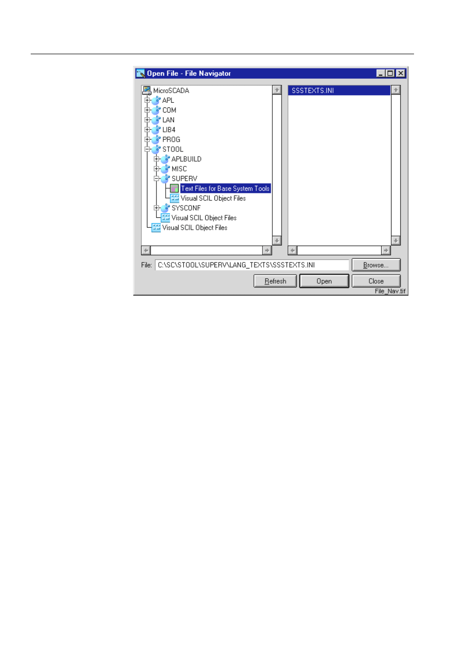
166
1MRS751880-MEN
LIB 500 Configuration Manual
LIB 500
8. System self supervision Configuration Guide
)LJ
)LOHIRU6XSHUYLVLRQ%DVHWH[WVVHOHFWHGLQWKH)LOH1DYLJDWRU
When the file is selected in above dialog, the contents of texts become displayed into
main view of Text Translation Tool, see (see Fig. 8.4.3.-2). Editing of each text
identifier is occurred by selecting the appropriate text item from the list and using
the Edit area in bottom of main view for typing the new text string. When text
identifier is modified, there is need to add double quotation marks around localized
text string. After the changes have been made with the tool, new section names with
added language identifier are constructed into file, when File – Save is selected from
the menu bar. More information about usage of Text Translation Tool can be found
from the System Management manual.
The used language to be used by the Supervision Base is defined in the application
object definition of MicroSCADA base system, i.e. to the value of APL:BLA
attribute.The default text file includes as a default all the texts with English
language. In the following is an example of the beginning of the text file delivered
together with Supervision Base.
Table 8.4.3-1
The beginning of a text file for Supervision Base
[EN]
Prefix_of_Operating_System="OS"
Prefix_of_Base_System="SYS"
Prefix_of_Application="APL"
Prefix_of_Link="Link"
Prefix_of_Node="Node"
Prefix_of_Net="NET"
Prefix_of_Net_Line="Line"
Prefix_of_Station="Station"
Prefix_of_Printer="Printer"

1MRS751880-MEN
LIB 500
167
LIB 500 Configuration Manual
Configuration Guide
8. System self supervision
8
Prefix_of_SLCM="SLCM"
Status_of_Net="Status of NET "
Status_of_Net_Line="Status of line "
Status_of_Net_Redundant="Status of redundant NET "
Status_of_Node="Node "
Status_of_Station="Status of station "
Status_of_SLCM="Status of LON Clock Master "
Status_of_Printer="Status of printer "
Status_of_Operating_System="Status of Operating System "
Status_of_Base_System="Status of Base System "
Status_of_Application_AS_Primary="Status of Application state "
Event_Cha_of_APL_EVENT="Event channel for predefined event of APL_EVENT"
Event_Cha_of_SYS_EVENT="Event channel for predefined event of SYS_EVENT"
Event_Cha_of_OS_EVENT="Event channel for predefined event of OS_EVENT"
Event_Cha_of_UNDEF_PROC="Event channel for predefined event of UNDEF_PROC"
Printer_Output_Lost="Connection to the printer lost"
Application_APL_AS_Cold_Primary="Application is not running"
Application_APL_AS_Cold_Secondary="Application is not running (external
node)"
Application_APL_AS_Warm_Primary="Application is in stand-by mode"
Application_APL_AS_Hot_Primary="Application is running"
Station_UN_Suspended="Connection to the station lost"
Station_UN_Running="Connection to the station re-established"
SLCM_Faulty="LON Clock Master faulty clock status"
SLCM_Normal="LON Clock Master normal clock status"
Node_NOD_Lost="Connection to the node lost"
Node_NOD_Found="Connection to the node established"
Printer_PRI_Output_Lost="Connection to the printer lost"
Operating_System_SYS="System Event Log from Operating System"
Operating_System_SEC="Security Event Log from Operating System"
Operating_System_APL="Application Event Log from Operating System"
Operating_System_System_Information="System information"
Operating_System_System_Warning="System warning"
Operating_System_System_Error="System error"
Operating_System_System_Audit_Success="System audit success"
Operating_System_System_Audit_Failure="System audit failure"
Operating_System_Security_Information="Security information"
Operating_System_Security_Warning="Security warning"
Operating_System_Security_Error="Security error"
Log_Prefix_of_SLCM_Normal="Normal state"
Log_Prefix_of_SLCM_Faulty="Faulty state"
Log_Prefix_of_SLCM_Bit="Bit #"
Log_Prefix_of_SLCM_Bit_0_Value_0="No connection to external clock."
Log_Prefix_of_SLCM_Bit_0_Value_1="Connection to external clock OK."
If project specific bits have been added into default event filtering file to receive
more supervision event bit information from the LON Clock Master, new key values
should be added into this file to display the new information also in Supervision Log
Viewer. The number after the prefix Log_Prefix_of_SLCM_Bit_ specifies the
number of bit to be supervised, and the last number in key name presents the bit state
(0 = reset, 1 = set). The purpose for added project specific key names can be
concluded from the documentation delivered together with LON Clock Master card
describing the contents of NV_CLOCK_STATUS_1 network variable type.
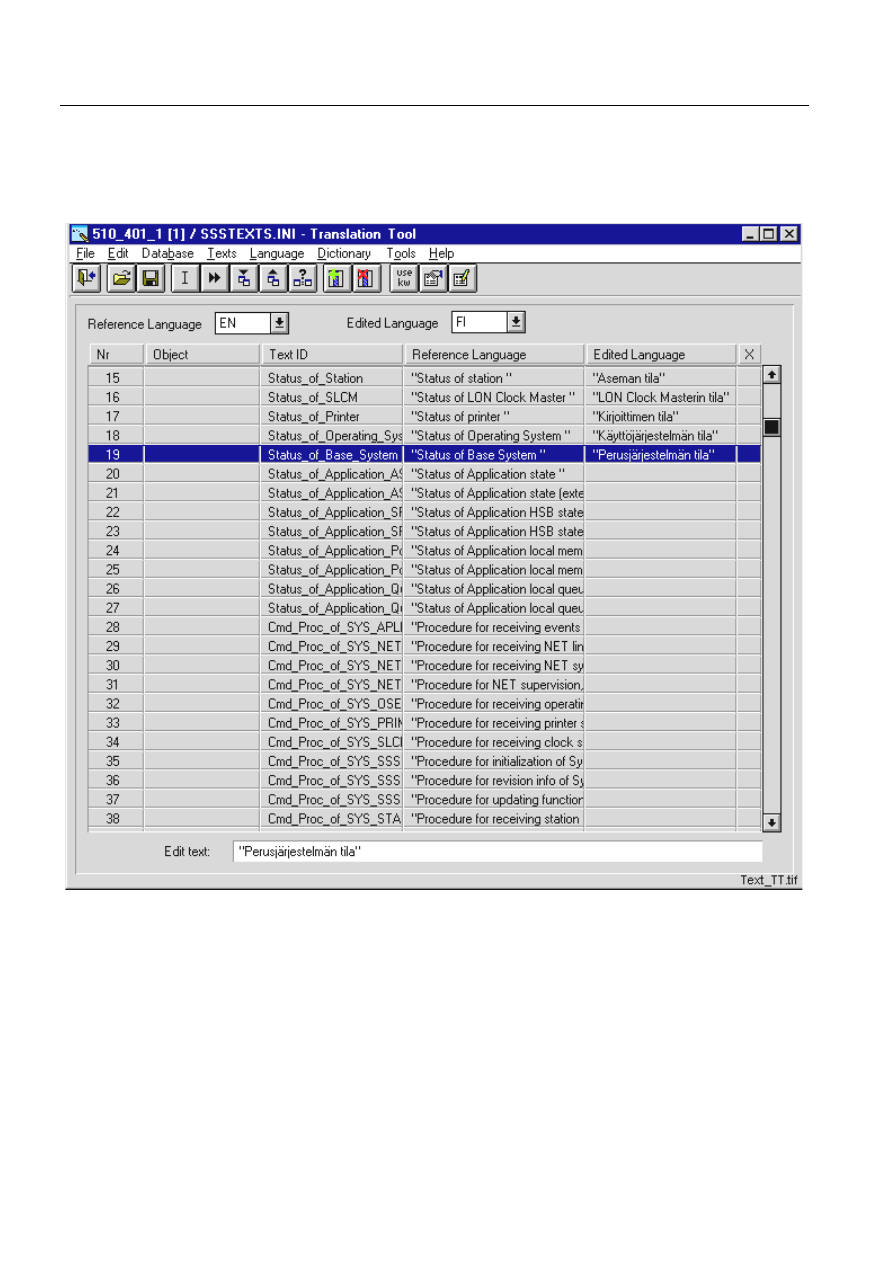
168
1MRS751880-MEN
LIB 500 Configuration Manual
LIB 500
8. System self supervision Configuration Guide
In the following example are text translations for new project specific bit 4 added to
be supported by Supervision Base and shown in Supervision Log Viewer.
Log_Prefix_of_SLCM_Bit_4_Value_0="No DST change within next hour."
Log_Prefix_of_SLCM_Bit_4_Value_1="DST change coming within an hour."
)LJ
0DLQYLHZRI7H[W7UDQVODWLRQ7RROZLWK6XSHUYLVLRQ%DVHWH[WILOH
8.4.4.
General parameters
The general parameters that have effect on the functionality of Supervision Base are
stored into permanent file located in folder /STOOL/SUPERV with file name
SSS_SETUP.SCL. Please note that if the application specific modifications to the
general parameters are needed, the configuration file can be copied under the
application folder /SUPERV and do the modifications there. At run-time these
definitions are kept in the application object definition of MicroSCADA base
system, i.e. in the APL:BSV45 attribute.
1MRS751880-MEN
LIB 500
169
LIB 500 Configuration Manual
Configuration Guide
8. System self supervision
8
When the MicroSCADA base system starts application with enabled Supervision
Base functionality, the contents of these general parameters are read from the
permanent file and assigned into application object definition to be accessed during
supervision routing, when events occur in the system.
By changing the general parameters the functionality of Supervision Base can be
adjusted in the following:
• Paths and files
• Events and alarms
• Events in stations
• Intervals and timeout
• Log file settings
When making changes to the default SSS_SETUP.SCL Supervision Base general
parameter file, it is preferred to use the SCIL Editor with Syntax Checking function
enabled. This is because, the format of this file follows the SCIL syntax, and in case
of SCIL syntax errors may lead to the Supervision Base to the unsteady state at start-
up. The Syntax Checking function is enabled by selecting Options – Syntax Check
at Save from the menu bar of SCIL Editor. More information about general
parameters of Supervision Base is included in the following sections.
The modifications related to Supervision Base general parameter file has to be done
before enabling the System Self Supervision functionality.
8.4.4.1.
Paths and files
These parameters define for example the location of System Self Supervision 2.x
root folder under application, where system self supervision configuration
information for Supervision Base is stored. Also the references to the files where
configuration file of included supervised objects, event filtering file, events file and
text translation file are located can be found inside this category.
Table 8.4.4.1-1
Paths and Files
An example of the SCIL statements that define the reference to Paths and Files for
general parameters to be used by the Supervision Base.
#CREATE SYS_SSSET:V = LIST(-
FILE_PATH = %t_File_Path,-
FILE_NAME_OF_CONF_INI = "’t_File_Path’/SSSConf.ini",-
FILE_NAME_OF_FILTER_INI = "’t_File_Path’/SSSFilter.ini",-
FILE_NAME_OF_EVENT_INI = "’t_File_Path’/SSSEvent.ini",-
Parameter
Functionality
FILE_PATH
File path for System Self Supervision 2.x under application
FILE_NAME_OF_CONF_INI
File path and name for the configuration file
FILE_NAME_OF_FILTER_INI
File path and name for the event filtering file
FILE_NAME_OF_EVENT_INI
File path and name for the event file
FILE_NAME_OF_LANG_INI
File path and name for the text translation file
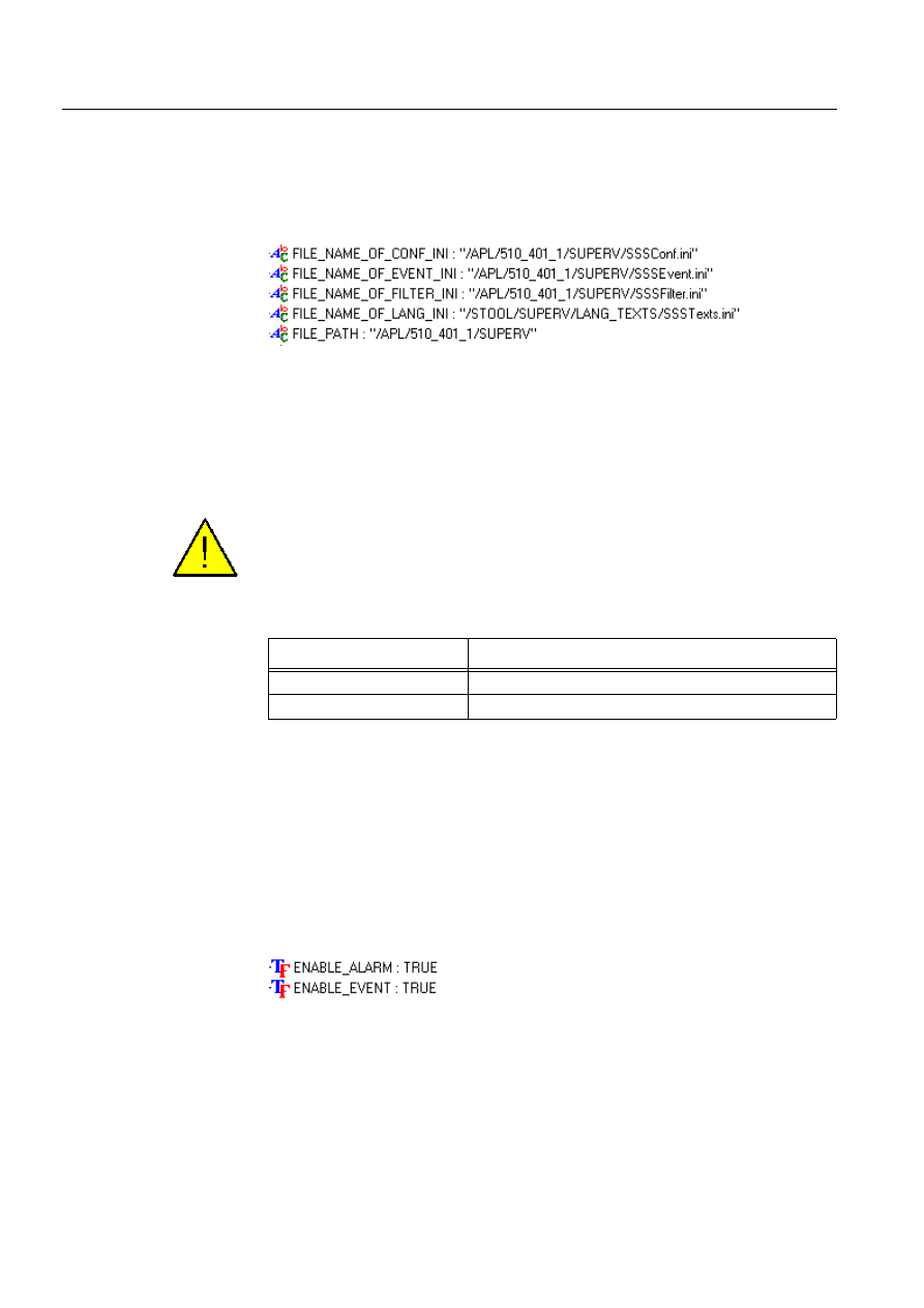
170
1MRS751880-MEN
LIB 500 Configuration Manual
LIB 500
8. System self supervision Configuration Guide
FILE_NAME_OF_LANG_INI = "’t_Lang_Path’/SSSTexts.ini",-
...
An example of these parameter names, values and SCIL data types at run-time in
running MicroSCADA system with enabled Supervision Base functionality can be
found from (see Fig. 8.4.4.1.-1) below.
)LJ &RQWHQWVRI3DWKVDQG)LOHVGHILQLWLRQV
8.4.4.2.
Events and alarms
These parameters define whether event or alarm activation is enabled or not by the
Supervision Base. As a default, both event and alarm activation is enabled. If there
is need to disable either event or alarm activation, the value FALSE should be used.
When event or alarm activation is disabled in Supervision Base, the events and
alarms do not anymore appear into Event or Alarm List, but events are collected into
log files and thus shown in the Supervision Log Viewer.
Table 8.4.4.2-1
Events and Alarms
An example of the SCIL statements that define the reference to Events and Alarms
for general parameters to be used by the Supervision Base.
#CREATE SYS_SSSET:V = LIST(-
...
ENABLE_EVENT = TRUE,-
ENABLE_ALARM = TRUE,-
...
An example of these parameter names, values and SCIL data types at run-time in
running MicroSCADA system with enabled Supervision Base functionality can be
found from (see Fig. 8.4.4.2.-1) below.
)LJ &RQWHQWVRI(YHQWVDQG$ODUPVGHILQLWLRQV
8.4.4.3.
Events in stations
These parameters define whether events in stations (APL_EVENT predefined event
channel is triggered) or system messages in station (message received into report
process informing the status of communication device) are collected by the
Parameter
Functionality
ENABLE_EVENT
Enable/Disable activation of the events
ENABLE_ALARM
Enable/Disable activation of the alarms
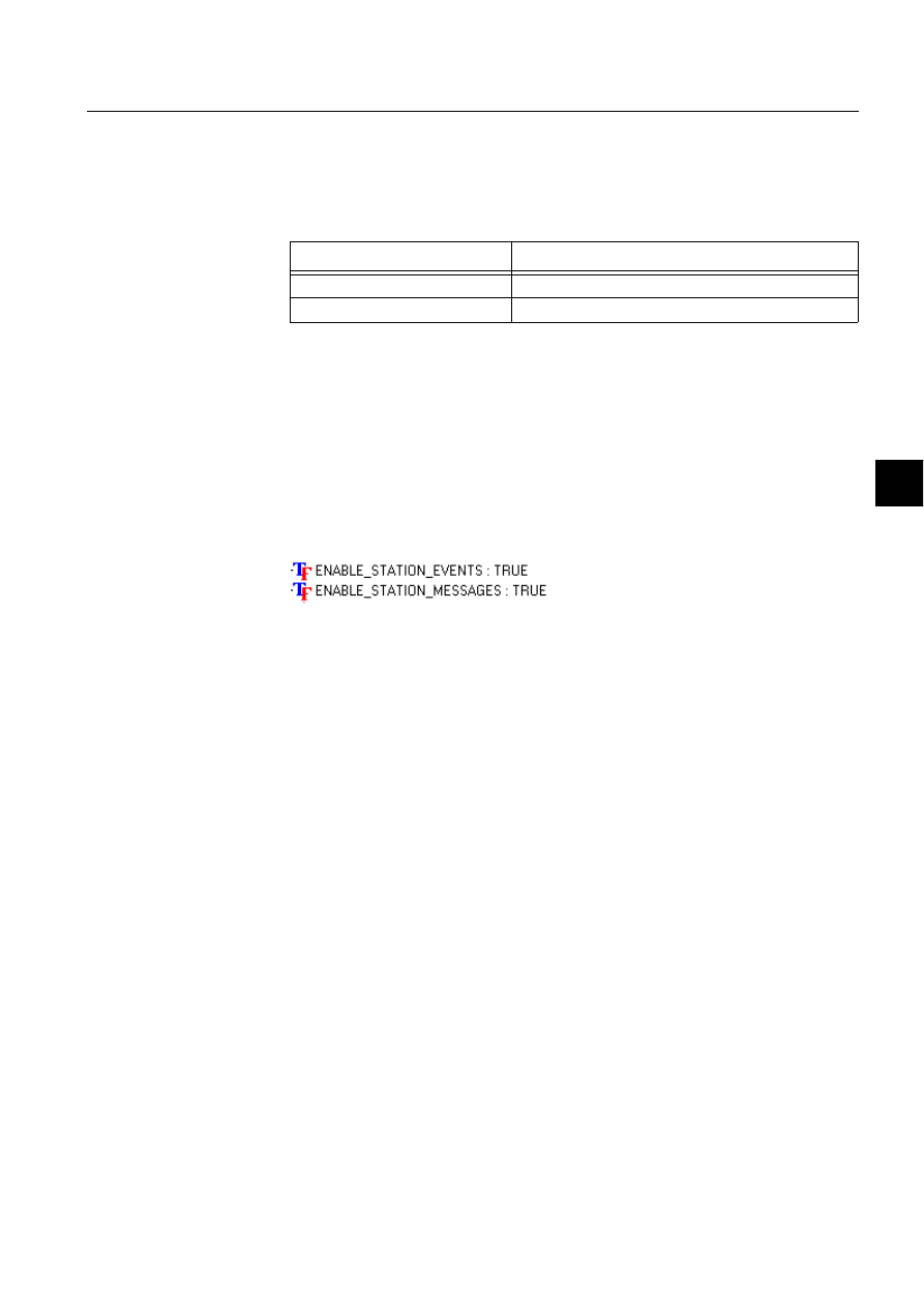
1MRS751880-MEN
LIB 500
171
LIB 500 Configuration Manual
Configuration Guide
8. System self supervision
8
Supervision Base or not. If there is need to disable this collect mechanism, the value
FALSE should be used in SSS_SETUP.SCL file. As default, all the event
information is collected through events in stations or system messages in station
mechanism.
Table 8.4.4.3-1
Events in Stations
An example of the SCIL statements that define the reference to Events in Stations
for general parameters to be used by the Supervision Base.
#CREATE SYS_SSSET:V = LIST(-
...
ENABLE_STATION_EVENTS = TRUE,-
ENABLE_STATION_MESSAGES = TRUE,-
...
An example of these parameter names, values and SCIL data types at run-time in
running MicroSCADA system with enabled Supervision Base functionality can be
found from (see Fig. 8.4.4.3.-1) below.
)LJ &RQWHQWVRI(YHQWVLQ6WDWLRQVGHILQLWLRQV
8.4.4.4.
Intervals and timeout
These parameters define, what are the used interval and timeout values of
Supervision Base for collecting supervision information. These values are separated
into 3 different categories according to following: the communication node is
stopped, state of external application is queried to application where Supervision
Routing is running or read of communication station property, e.g. state of signal,
leads NET to timeout situation.
As default, the 20 second interval time is applied for queries to find out the state of
communication node and external application. If timeout occurs, when
communication station property is read, the occurred default timeout takes time 5
second. Note that the global time-out value is 60 seconds (SYS:BTI attribute), which
is now temporarily overridden by the Supervision Base during routing of event and
later the previous time-out value is returned to the system.
Please note that the used interval times can be changed within the application before
the application objects of the System Self Supervision are created. Before creation
of the application objects, change of the used interval times has to be done directly
to the time channel definitions of the System Self Supervision.
Parameter
Functionality
ENABLE_STATION_EVENTS
Enable/Disable events in station (i.e. APL_EVENT)
ENABLE_STATION_MESSAGES
Enable/Disable system messages in station
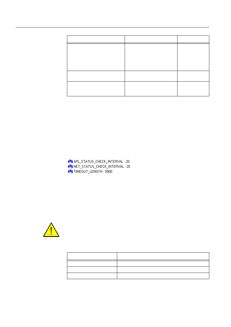
172
1MRS751880-MEN
LIB 500 Configuration Manual
LIB 500
8. System self supervision Configuration Guide
Table 8.4.4.4-1
Intervals and Timeouts
An example of the SCIL statements that define the values to Intervals and Timeout
for general parameters to be used by the Supervision Base.
#CREATE SYS_SSSET:V = LIST(-
...
APL_STATUS_CHECK_INTERVAL = 20,-
NET_STATUS_CHECK_INTERVAL = 20,-
TIMEOUT_LENGTH = 5000,-
...
An example of these parameter names, values and SCIL data types at run-time in
running MicroSCADA system with enabled Supervision Base functionality can be
found from (see Fig. 8.4.4.4.-1) below.
)LJ &RQWHQWVRI,QWHUYDOVDQG7LPHRXWGHILQLWLRQV
8.4.4.5.
Log file settings
These parameters define, what are the used settings for generated log files by the
Supervision Base. It is possible to enable or disable the log file generation, the
number of the rows included into log file can be parametrized as well as used field
separator between information related to each event.
When log file generation is disabled in Supervision Base, the events are not any
more collected into log files, and thus not shown in Supervision Log Viewer.
Table 8.4.4.5-1
Log File Settings
Parameter
Functionality
Range
APL_STATUS_CHECK_INTERVAL Interval for application status
checking from external
MicroSCADA base system
computer (in case of external
application or a hot-stand-by
system)
1 - 2 147 483 647
NET_STATUS_CHECK_INTERVAL Interval for communication unit
status checking
1 – 2 147 483 647
TIMEOUT_LENGTH
Default timeout length used
within System Self Supervision
2.x
1 – 2 147 483 647
Parameter
Functionality
ENABLE_LOG
Enable/Disable activation of the log file events
MAX_LENGTH_OF_LOG
Default length of the log file
LOG_SEPARATOR
Default separator used in the log file
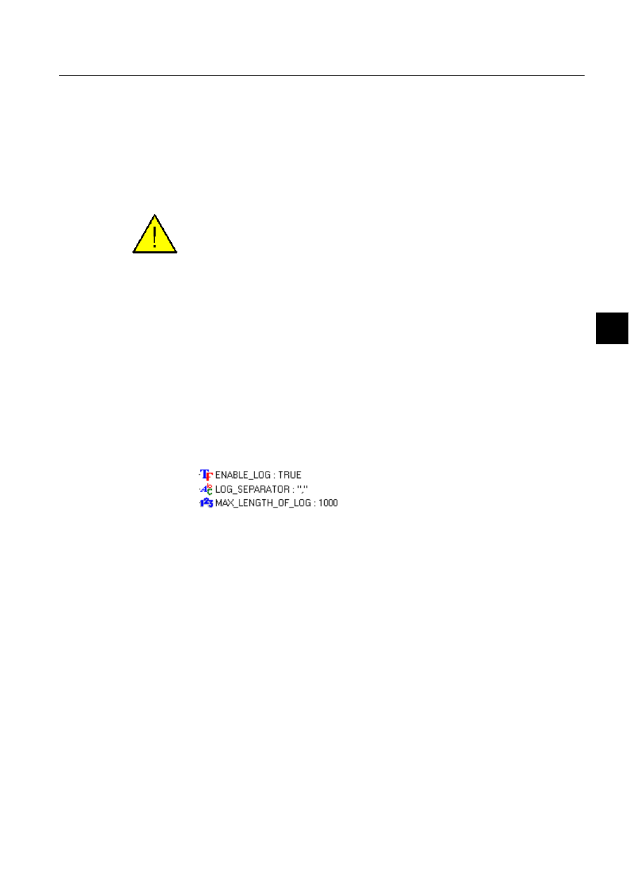
1MRS751880-MEN
LIB 500
173
LIB 500 Configuration Manual
Configuration Guide
8. System self supervision
8
Supervision Base uses log file collection as default. The length of each log file is
defined to be 1000 events. In order to avoid loss of events it is not recommended to
increase the limit to over 1000 events per file. The separator used between
information of an event is comma. If the field separator is changed to semicolon the
contents of active system message log file could be the following:
1999-12-23 08:37:12.592;UN;3;;;SUSPENDED
1999-12-23 08:37:12.592;STA;3;3;2;13371
1999-12-23 08:37:12.632;STA;4;3;2;13278
The defined field separator has to be same for all events in log files, because
otherwise the Supervision Log Viewer is not capable for displaying the events. This
means that if the field separator is changed later, when Supervision Base has already
collected the generated log files, the previous log files has to be removed from the
application’s SUPERV folder manually.
An example of the SCIL statements that define the values to Log File Settings for
general parameters to be used by the Supervision Base.
#CREATE SYS_SSSET:V = LIST(-
...
ENABLE_LOG = TRUE,-
MAX_LENGTH_OF_LOG = 1000,-
LOG_SEPARATOR = “,”,-
...
An example of these parameter names, values and SCIL data types at run-time in
running MicroSCADA system with enabled Supervision Base functionality can be
found from (see Fig. 8.4.4.5.-1) below.
)LJ &RQWHQWVRI/RJ)LOH6HWWLQJVGHILQLWLRQV
8.5.
System monitoring general
This chapter describes the monitoring part seen from the library implementations in
LIB 500 System Self Supervision
8.5.1.
Installing and configuring System Self Supervision functions
The installation of picture functions is divided into two main parts:
1. Installation
2. Configuration.
The system tools, i.e. Installation Tool, Standard Configuration Tool, Process
Object Tool and the Representation Tool are shortly described in chapter 2.
8.5.1.1.
Installing
The picture function name (ID) should be unique within the same picture, and it is
wise to use such an identification that is universal, i.e. the identification does not
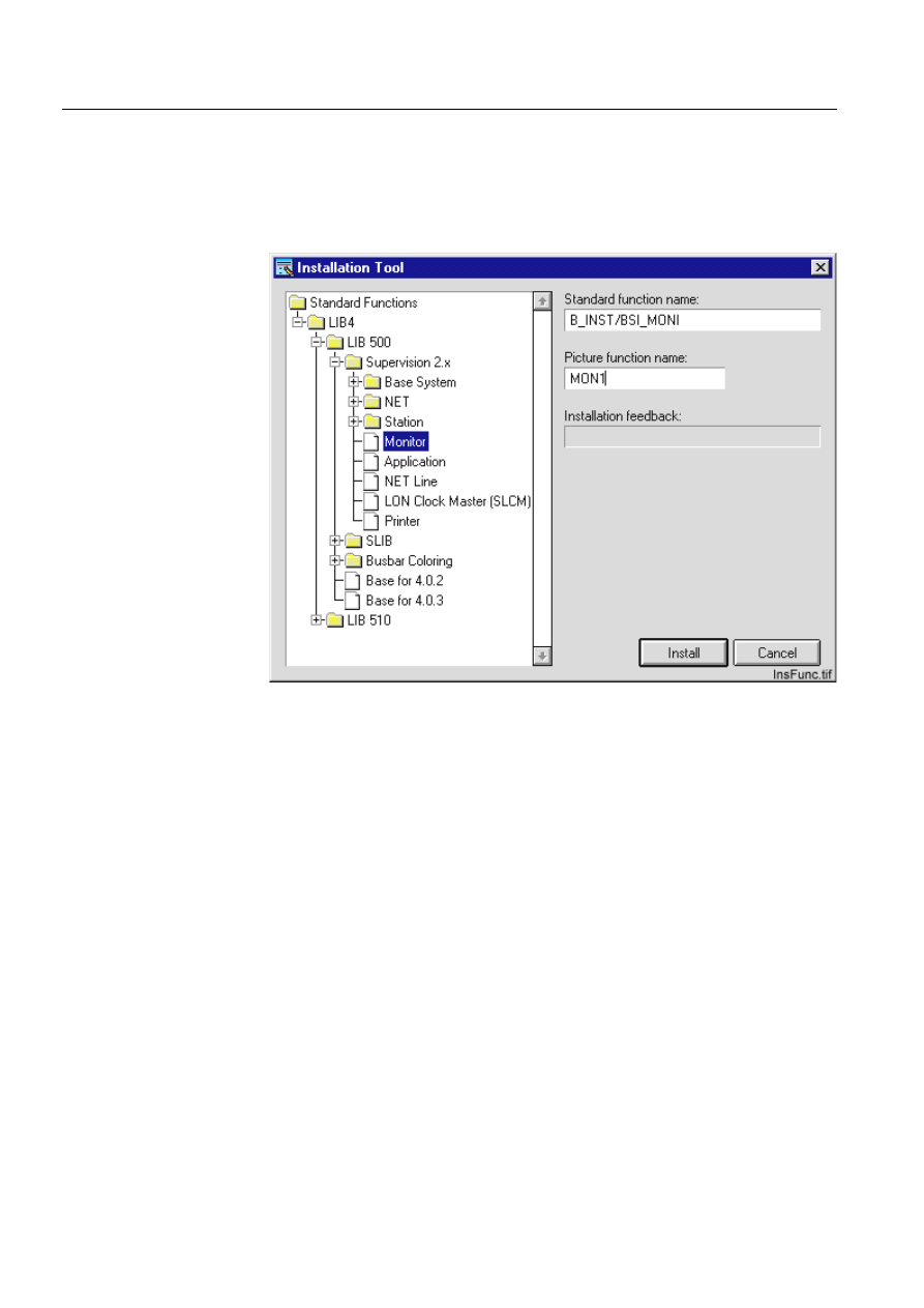
174
1MRS751880-MEN
LIB 500 Configuration Manual
LIB 500
8. System self supervision Configuration Guide
refer to any particular device. This makes sense when copying the system
supervision picture (*.PIC) and saving it to another name, and then reusing it again
in another project.
Allowed characters are the letters A-Z, all digits and the underscore (_). However,
the name of the picture function cannot begin with a digit or an underscore.
)LJ ([DPSOHRIWKHLQVWDOODWLRQRI6\VWHP6HOI6XSHUYLVLRQIXQFWLRQV
8.5.1.2.
Configuring
The object identification in the database
The structure and usage of the object identification in the System Self Supervision
is described in detail in the Section 8.3.2
The object identification in the application
Owing to the obligatory substation and bay identification field in the database, there
is a setting tool which defines how the OI-attribute will be shown in printouts, event
list, alarm list, dialogs, etc.
The configuration of the OI-attribute visibility is global, i.e. all functions done by
the LIB 5xx 4.0.3 follow the same definition. The fields starting from the beginning
and/or the end of OI-attribute can be defined as not visible. A field between visible
fields cannot be set as invisible. The reason for this lies in the performance
requirements.
In Application Settings view, the setting tool Show Object Identification for setting
the OI-attribute visibility in the application can be found in the Tools menu.

1MRS751880-MEN
LIB 500
175
LIB 500 Configuration Manual
Configuration Guide
8. System self supervision
8
The naming convention of the database
The naming convention of the database used as a default in the System Self
Supervision is described in detail in the Section 8.3.2.
Application and monitor language
The application and monitor language used as a default in the System Self
Supervision is described in detail in the Section 8.3.2.
8.5.2.
Graphical representations and functionality
In this chapter, the general functionality of the picture functions is described. After
general principles and common functions, all the different picture functions are
described in detail, one by one.
Some principles are general and used for all picture functions (colors,
representations etc.). A description of these general principles is provided below.
8.5.2.1.
Status indication
The status presentation for an object consists of two parts: a representation symbol
and a color. These two define the exact object status. Also in certain cases, an
additional information may be given as text beside the picture function.
8.5.2.2.
Color coding
The current state is indicated by different symbols. The color of the symbol gives
additional information on the object.
Table 8.5.2.2-1
Color Coding
8.5.2.3.
Color definitions
The colors used in LIB 500 System Self Supervision refers to the following System
Colors (M scope). The colors can be changed by using the Color Settings Tool that
is being opened from the System Configuration folder in the Tool Manager.
Color
Status
DARK GREY
Not in use
GREY
Static (i.e. no supervision diagnostic available)
WHITE
Selected on monitor
MAGENTA
Undefined (i.e. not sampled, not updated or invalid
value)
RED, FLASHING
Alarm, unacknowledged
RED
Alarm, acknowledged
GREEN
Normal state, in use

176
1MRS751880-MEN
LIB 500 Configuration Manual
LIB 500
8. System self supervision Configuration Guide
Table 8.5.2.3-1
Color definitions
8.5.2.4.
Attribute expressions for color definitions
Table 8.5.2.4-1
Attribute expressions for color definitions
8.5.3.
Representations
The name of the representation (symbol set) used for the picture function state
indication can be configured with the Representation Tool. The name of the
representation can be selected with the selector called Representation when the
preview window shows an example of the selected symbol set.
Color
Color definition
System Color
DARK GREY
Bottom shadow
(“M”,9)
GREY
Normal background
(”M”,1)
WHITE
Selected object
(“M”,27)
MAGENTA
Not updated
(“M”,30)
RED
Alarm
(“M”,16)
GREEN
Normal, dynamics
(“M”,32)
Description
Attribute used
Color
Comment
Not in use
AI = -1
Dark grey
Color definition used
only in the System
Self Supervision
Static
-
Grey
Color definition used
only in the System
Self Supervision
Selected on the
MicroSCADA screen
-
White
-
Not sampled
OS = 10
Magenta
No value is
presented
Not updated
OS = 2 or OS = 4..9
Magenta
Last known value is
presented
Invalid value
OS = 1
Magenta
Last known value is
presented
Alarm, unacknowledged
AL = 1 and AR = 0
Red, flashing
-
Alarm, acknowledged
AL = 1 and AR = 1
Red
-
Normal state, in use
AI = 0
Green
-
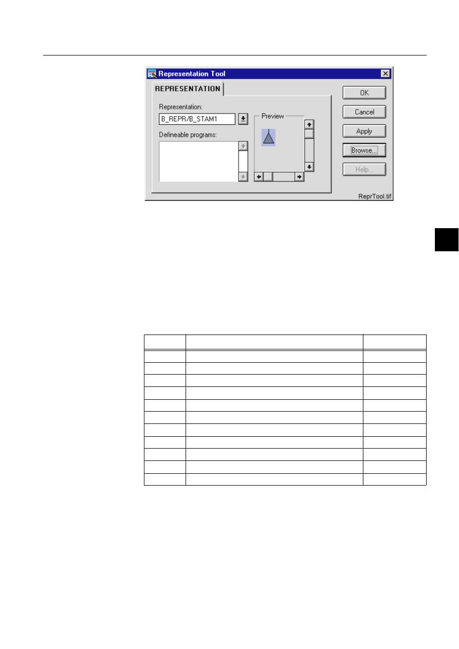
1MRS751880-MEN
LIB 500
177
LIB 500 Configuration Manual
Configuration Guide
8. System self supervision
8
)LJ
([DPSOHRIWKH5HSUHVHQWDWLRQ7RRO
If there is no appropriate symbol set, there is the possibility to make and use a user
-defined representation set. In that case one of the existing representation sets can be
copied into a representation file /APLMOD4/USE/APLMOD4.PIR under the
application folder and each representation may be modified as needed. If object
specific representations are needed, the representation set (under the application)
may be renamed and the name of the representation may be written into the selector
with the logical path.
For example:
B_REPR/MY_SET
Table 8.5.3-1
The picture functions requires a selector and a symbol for the
following conditions
8.5.4.
Information dialogs
As the picture functions are configured, the information dialogs may be displayed in
case the system configuration does not exist or the system configuration includes
attribute value definitions that do not allow all the diagnostic available for the
System Self Supervision.
The information dialog may appear in the following cases:
Selector
Condition
Default color
-1
Not in use
Dark grey
0
Static (i.e. no supervision diagnostic available)
Grey
1
Selected on monitor
White
2
<reserved for future use>
-
3
Undefined (i.e. not sampled, not updated or invalid value) Magenta
4
Alarm, unacknowledged
Red, flashing
5
Alarm, acknowledged
Red
6
<reserved for future use>
-
7
<reserved for future use>
-
8
<reserved for future use>
-
9
Normal state, in use
Green
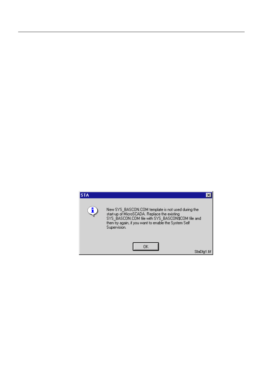
178
1MRS751880-MEN
LIB 500 Configuration Manual
LIB 500
8. System self supervision Configuration Guide
• Old SYS_BASCON.COM template is used
• System Self Supervision routing is enabled in the SYS_BASCON.COM
• Picture function is not configured, even though the Standard Configuration Tool
is opened for the selected picture function
• System configuration for the configured picture function object is either
undefined or the communication unit (NET) is not currently in use. In addition, in
case of the LON Clock Master, the station type or number is not assigned to the
LON Clock Master
• Communication protocol used in the communication unit line or the station type
for the configured picture function object is not supported by the System Self
Supervision
• Configuration discrepancy encountered
• Object number for the configured picture function object changed since the
previous configuration
A description of the information dialogs is provided below.
8.5.4.1.
Old SYS_BASCON.COM
If previous SYS_BASCON.COM template is being used, the following information
dialog is displayed. This is because, for the System Self Supervision routing, the
base system object definition (SYS:BSV) has to include a new attribute called
B_SSS_MECH_IN_USE on its second element. An example of this attribute can be
found from the new template delivered together with MicroSCADA installation in
the file SYS_BASCON$COM. Refer to the Section 8.3.1.1 for detailed information.
)LJ 2OG6<6B%$6&21&20WHPSODWHXVHG
8.5.4.2.
System Self Supervision routing disabled
If the System Self Supervision routing is disabled in the SYS_BASCON.COM, the
following information dialog is displayed. Thus the System Self Supervision routing
is disabled and there is no supervision diagnostic available within the supervision
monitoring objects. Refer to the Section 8.3.1.1 for detailed information.
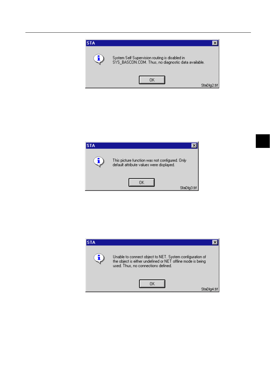
1MRS751880-MEN
LIB 500
179
LIB 500 Configuration Manual
Configuration Guide
8. System self supervision
8
)LJ 6\VWHP6HOI6XSHUYLVLRQURXWLQJGLVDEOHG
8.5.4.3.
Picture function not configured
If the Standard Configuration Tool is opened for the installed picture functions,
default attribute settings are shown. Furthermore, if the Standard Configuration Tool
is closed by clicking Cancel, (see (see Fig. 8.6.5.5.-1)), and the picture function is
not configured, the following information dialog is displayed.
)LJ 3LFWXUH)XQFWLRQQRWFRQILJXUHG
8.5.4.4.
Unable to connect
If the system configuration of the installed picture function object is undefined or
the communication unit (NET) is not currently in use, the following information
dialog is displayed.
)LJ 8QDEOHWRFRQQHFW
In case of the standard function for the station is defined and the installed object
refers to a device type of LMK, the following information dialog is displayed in the
case of Diagnostic Interval (DI) attribute for communication system object of LMK
station is 0.
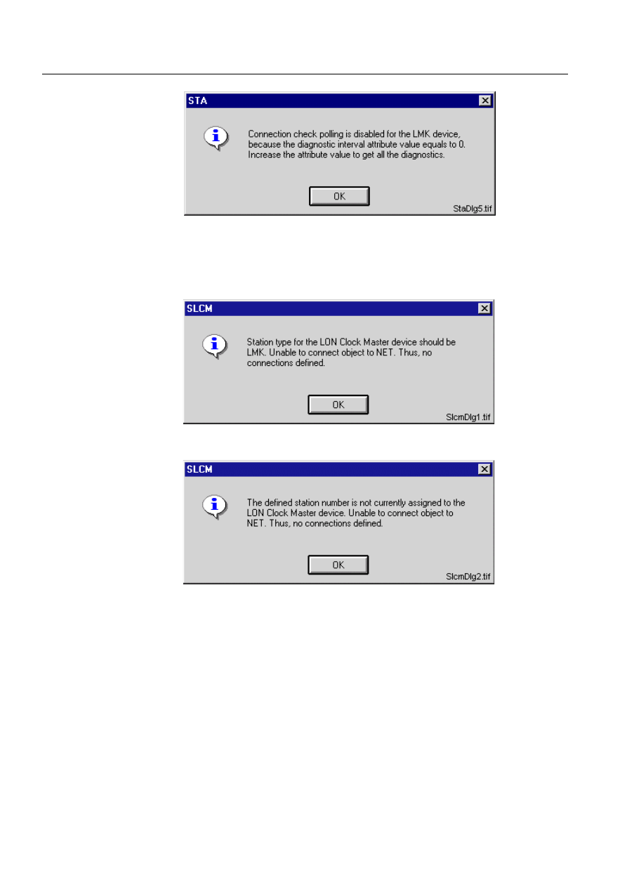
180
1MRS751880-MEN
LIB 500 Configuration Manual
LIB 500
8. System self supervision Configuration Guide
)LJ 'LDJQRVWLFLQWHUYDODWWULEXWHRI/0.GHYLFHHTXDOVWR
In case of the picture function for the LON Clock Master (SLCM) is defined and the
installed object does not refer to a LON Clock Master (SLCM) device, one of the
following information dialogs are displayed.
)LJ 6WDWLRQW\SHGRHVQRWUHIHUWRD/21&ORFN0DVWHU6/&0GHYLFH
)LJ 6WDWLRQQXPEHUGRHVQRWUHIHUWRD/21&ORFN0DVWHU6/&0
GHYLFH
8.5.4.5.
Not supported by the System Self Supervision
If the communication unit line (NET line) picture function is installed and the
communication protocol for the installed picture function object is not supported by
the System Self Supervision, the following information dialog is displayed.
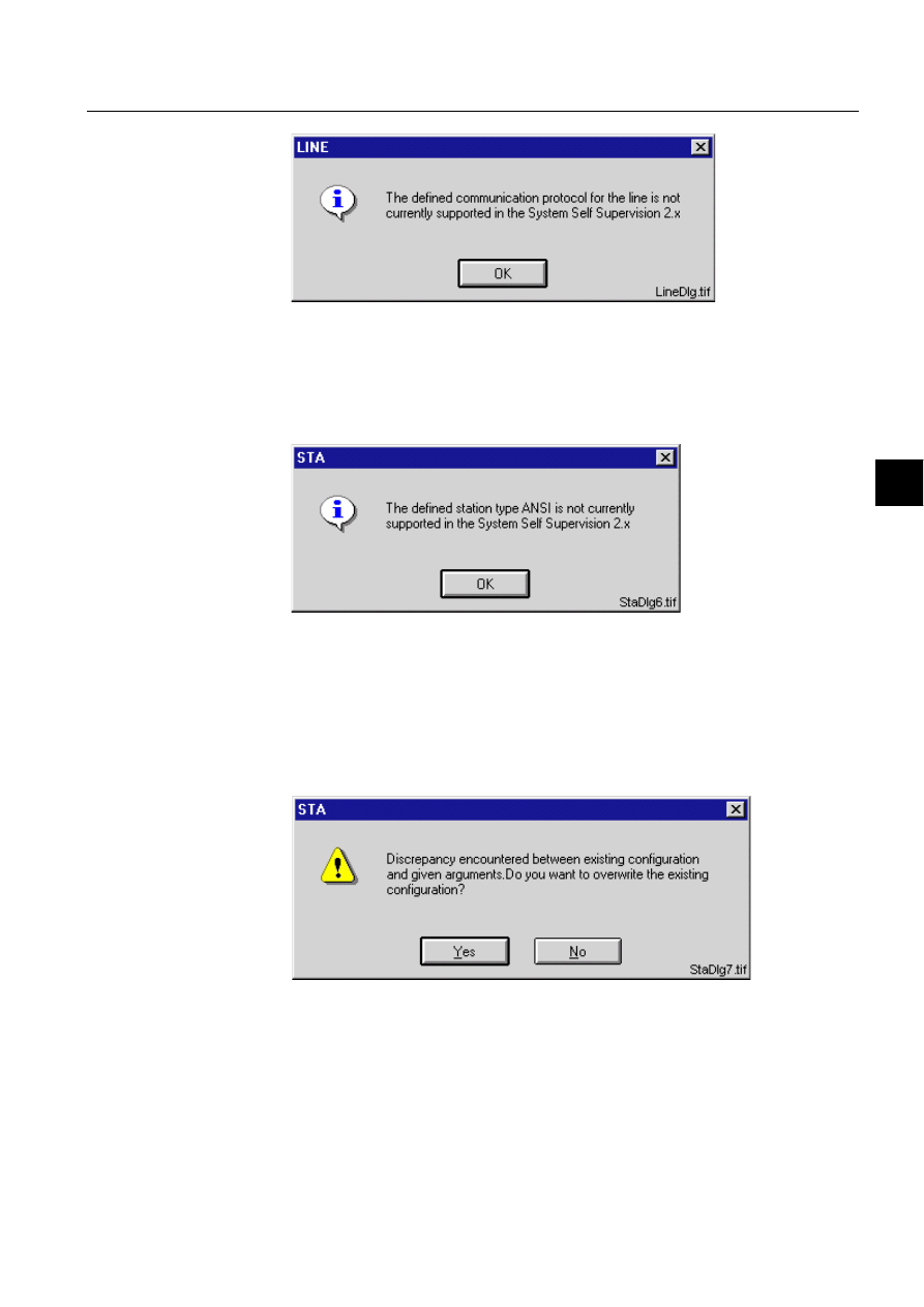
1MRS751880-MEN
LIB 500
181
LIB 500 Configuration Manual
Configuration Guide
8. System self supervision
8
)LJ 'HILQHGFRPPXQLFDWLRQSURWRFROLVQRWVXSSRUWHGE\WKH6\VWHP
6HOI6XSHUYLVLRQ
As the station picture function is installed and the station type for the installed
picture function object is not supported by the System Self Supervision, the
following information dialog is displayed.
)LJ 'HILQHGVWDWLRQW\SHLVQRWVXSSRUWHGE\WKH6\VWHP6HOI
6XSHUYLVLRQ
8.5.4.6.
Configuration discrepancy
If the configuration data given in the standard function does not match with the
existing configuration stored in the initialisation file of the System Self Supervision,
the following information dialog is displayed.
)LJ 'LVFUHSDQF\HQFRXQWHUHG
8.5.4.7.
Object Number Changed Since Previous Configuration
If the object number of the installed standard function is changed after the
configuration of the object, the following information dialog is displayed. When Yes
is clicked, the previous object number is removed from the configuration file. If No

182
1MRS751880-MEN
LIB 500 Configuration Manual
LIB 500
8. System self supervision Configuration Guide
is clicked, the new object number is included and previous one is unaffected in the
configuration file of Supervision Base.
)LJ 2EMHFWQXPEHURIWKHVWDQGDUGIXQFWLRQFKDQJHG
8.6.
Monitor
8.6.1.
Target systems
MicroSCADA systems, especially system supervision pictures.
8.6.2.
Monitor support
• VS Local
• VS Remote
• X
8.6.3.
Features/options
• Versatile configuration
• Device information
• Help in all dialogs
8.6.4.
Picture function installation
This chapter describes the installation of picture functions for the System Self
Supervision monitor object. The picture function for the monitor is found in the
directory /LIB4/BASE/SYSTEM/INST/ and it should be installed by using LIB4
installation procedures (LIB4 - LIB 500 - Supervision 2.x - Monitor). This picture
function is configured by using the Standard Configuration Tool.
8.6.4.1.
Environmental requirements
In order for the monitor to have full functionality, the following component needs to
be installed first:
• Base for 4.0.3
8.6.4.2.
Installation
The size of the monitor picture function is 80 x 80 pixels (5 x 4 semigraphical
blocks). The button frame is drawn out of this area.
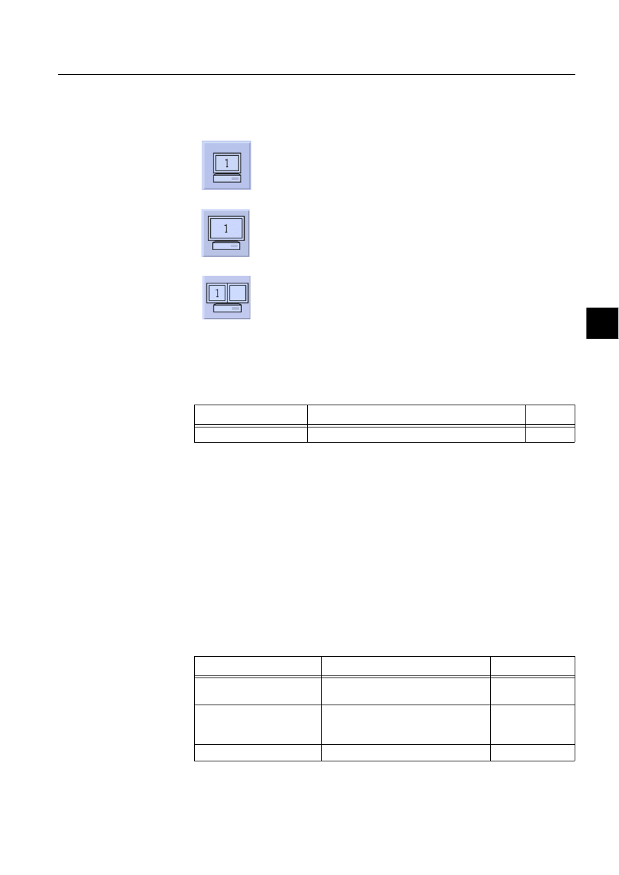
1MRS751880-MEN
LIB 500
183
LIB 500 Configuration Manual
Configuration Guide
8. System self supervision
8
(see Fig. 8.6.4.2.-1) presents all three different types of the monitor picture function
in typical installations.
)LJ ,QVWDOODWLRQIRUPRQLWRUSLFWXUHIXQFWLRQ
During the installation, the following information has to be given:
Table 8.6.4.2-1
Installation information
8.6.5.
Picture function configuration
8.6.5.1.
Preliminary work
Since the monitor picture function does not need any process objects in order to
work, no preliminary work is required. However, it is necessary to know the network
addresses or the network names of the computers to be supervised by the monitor
picture function.
8.6.5.2.
Configuration with Standard Configuration Tool
The monitor picture function has the following attributes to configure with the
Standard Configuration Tool.
Table 8.6.5.2-1
The attributes of the monitor picture function to configure
with the Standard Configuration Tool.
M1.tif
Single monitor (small)
M2.tif
Single monitor (big)
M3.tif
Double monitor
Attribute
Meaning
Default
Picture function name
Name of the picture function within the picture
-
Attribute
Meaning
Default
AUTHORIZATION_
GROUP
The name of the authorization group
SUPERVISION
LABEL
The abbreviation of the supervised
picture to be shown in the system
supervision picture.
-
LABEL_POSITION
Position of the label
TOP

184
1MRS751880-MEN
LIB 500 Configuration Manual
LIB 500
8. System self supervision Configuration Guide
8.6.5.3.
Configuration with Representation Tool
The monitor picture function has no attributes to configure with the Representation
Tool.
MONITOR_HOST_NAME
The LAN node name of the computer
SYS:BNN
MONITOR_ADDRESS
The IP (Internet Protocol)-address of
the computer
-
MONITOR_TYPE
The shape of the monitor symbol shown Single small
WRITE_DEVICE_INFO
(in Programs folder)
An optional program by which three (3)
lines of device information are written to
the picture function. The maximum
length of each line is 28 characters.
Attribute
Meaning
Default
Attribute
Meaning
AUTHORIZATION_GROUP
A selector type of an editable combo box to select the
authorization group for the object. The maximum length of
the text is 63 characters. The given text has to be usable as
a SCIL list attribute name (see the manual Programming
Language SCIL, 1MRS751849-MEN). The contents of the
selection list is taken from the existing authorization groups.
NOTE! The name may not be composed of two letters
followed by a number.
The attribute needs to be defined, if the object is wanted to
be included in some authorization group. The authorization
level of each user in this group can be defined afterwards by
the system manager with the User Management pictures.
LABEL
A text which will be placed outside the picture function
symbol as the picture is opened to the monitor. The position
of the text is determined by the LABEL_POSITION. The
maximum length of the LABEL is 15 characters.
LABEL_POSITION
A selector type of a combo box to select the position for the
LABEL text.
Valid values: "TOP", "BOTTOM", "LEFT" or "RIGHT"
MONITOR_HOST_NAME
The LAN node name of the computer (host name) from
which the number of open MicroSCADA monitors is to be
supervised.
Either the node name or the IP-address of the computer is
written on the MON<mon:number>:BSD attribute as the
remote VS or X monitor is opened.
MONITOR_ADDRESS
The IP-address of the computer from which the number of
open MicroSCADA monitors is to be supervised.
Either node name or IP-address of the computer is written
on the MONx:BSD attribute as the remote VS or X monitor is
opened.
MONITOR_TYPE
A selector type of a combo box to select the presentation of
the monitor object symbol.
Valid values: "Single big", "Single small" or "Double".
Default value: "Single small"
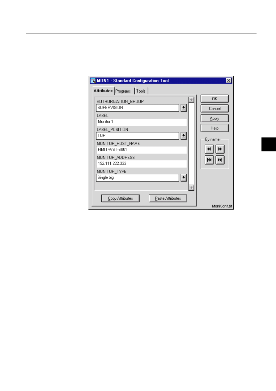
1MRS751880-MEN
LIB 500
185
LIB 500 Configuration Manual
Configuration Guide
8. System self supervision
8
8.6.5.4.
Configuration with Process Object Tool
The monitor picture function has no attributes to configure with the Process Object
Tool.
8.6.5.5.
An example of the monitor configuration
)LJ $QH[DPSOHRIWKHFRQILJXUDWLRQRIWKHPRQLWRUSLFWXUHIXQFWLRQ
8.6.5.6.
Information dialogs
As the monitor object is being configured, the Information dialogs may be displayed
in case the system configuration does not exist or the system configuration includes
attribute value definitions that do not allow all the diagnostic available for the
System Self Supervision. More information can be found in the Section 8.5.4.
8.6.6.
Application engineering information
8.6.6.1.
The structure of the monitor picture function
This chapter describes the structure of the monitor picture function. All pictures,
form pictures, help and other text files as well as all database objects are included.
The monitor picture function is a part of the System Self Supervision of LIB 500 and
has a directory /LIB4/BASE/SYSTEM/, and the standard LIB 500 sub-directories
INST, LANG0 and USE.
The installation of the “instance” picture function will automatically install “type”
picture function (BSI_MONT) if it does not already exist. The “type” picture
function contains all common programs for the “instance” picture function and it is
only visible at the Picture Editor.

186
1MRS751880-MEN
LIB 500 Configuration Manual
LIB 500
8. System self supervision Configuration Guide
8.6.6.2.
Pictures
Below there is a list of all monitor pictures and a short description of their
functionality. Dialogs are described in detail in the LIB 500 Operator’s Manual,
1MRS751885-MUM (Chapter 6). The paths are
/LIB4/BASE/SYSTEM/INST/
Table 8.6.6.2-1
A list of the monitor pictures and description of their
functionality (first path)
and /LIB4/BASE/SYSTEM/USE/
Table 8.6.6.2-2
A list of the monitor pictures and description of their
functionality (second path)
8.6.6.3.
Help text files
Below there is a list of the monitor help text files. The path is
/LIB4/BASE/SYSTEM/LANG0.
Table 8.6.6.3-1
A list of the monitor help text files
8.6.6.4.
Configuration files
The following configuration files are used by the monitor picture function. The path
is
LIB4/BASE/SYSTEM/INST/
Table 8.6.6.4-1
The configuration files used by the monitor picture function
Picture
Functionality
BSI_MONT.PIC
Common programs for all monitor picture functions
BSI_MONI.PIC
Picture function (5*4) for monitor object
Picture
Functionality
BSU_DLGA.PIC
Main dialog (common for all other picture functions, too).
BSU_DLGB.PIC
Device information dialog (common for all other picture
functions, too).
Help file
Functionality
BSI_MON2.HLP
Picture function installation help file
BSU_MON2.HLP
Main dialog help file
Configuration file
Functionality
BSI_MON2.DAT
Contains the configuration data for monitor object when it is
created, modified or deleted by configuration tools.
INDEX4_B11.TXT
Selection list of LIB 500 Rev 4.0.3 System Self Supervision
picture functions for installation tool (common for all other picture
functions, too).

1MRS751880-MEN
LIB 500
187
LIB 500 Configuration Manual
Configuration Guide
8. System self supervision
8
8.6.6.5.
Other text files
The following text files are used by the monitor. The path is
/LIB4/BASE/SYSTEM/USE/.
Table 8.6.6.5-1
The text files used by the monitor
8.6.6.6.
Process objects
The monitor picture object does not create any process objects of it’s own, but
utilises the B_MONITOR process objects created by the MicroSCADA login
picture. This process object has an index for each monitor opened to the system, and
the value of each B_MONITOR index indicates the state (open/closed/error) of the
monitor in question.
8.7.
Base system
8.7.1.
Target systems
MicroSCADA systems, especially system supervision pictures.
8.7.2.
Application support
• Local applications (in a single or in a hot-stand-by system)
• External applications (in a single system)
8.7.3.
Features/options
• Versatile configuration
• Device information
• Help in all dialogs
8.7.4.
Picture function installation
This chapter describes the installation of picture functions for the System Self
Supervision base system object. The picture function for the base system is found in
the directory /LIB4/BASE/SYSTEM/INST/ and it should be installed by using LIB4
installation procedures (LIB4 - LIB 500 - Supervision 2.x – Base System). This
picture function is configured by using standard configuration tools such as:
1. Standard Configuration Tool
2. Representation Tool
8.7.4.1.
Environmental requirements
In order for the base system object to have full functionality, the following
component needs to be installed first:
• Base for 4.0.3
Text file
Functionality
PATH4_B11.TXT
Contains the path definitions for the System Self Supervision
(common for all other picture functions, too).
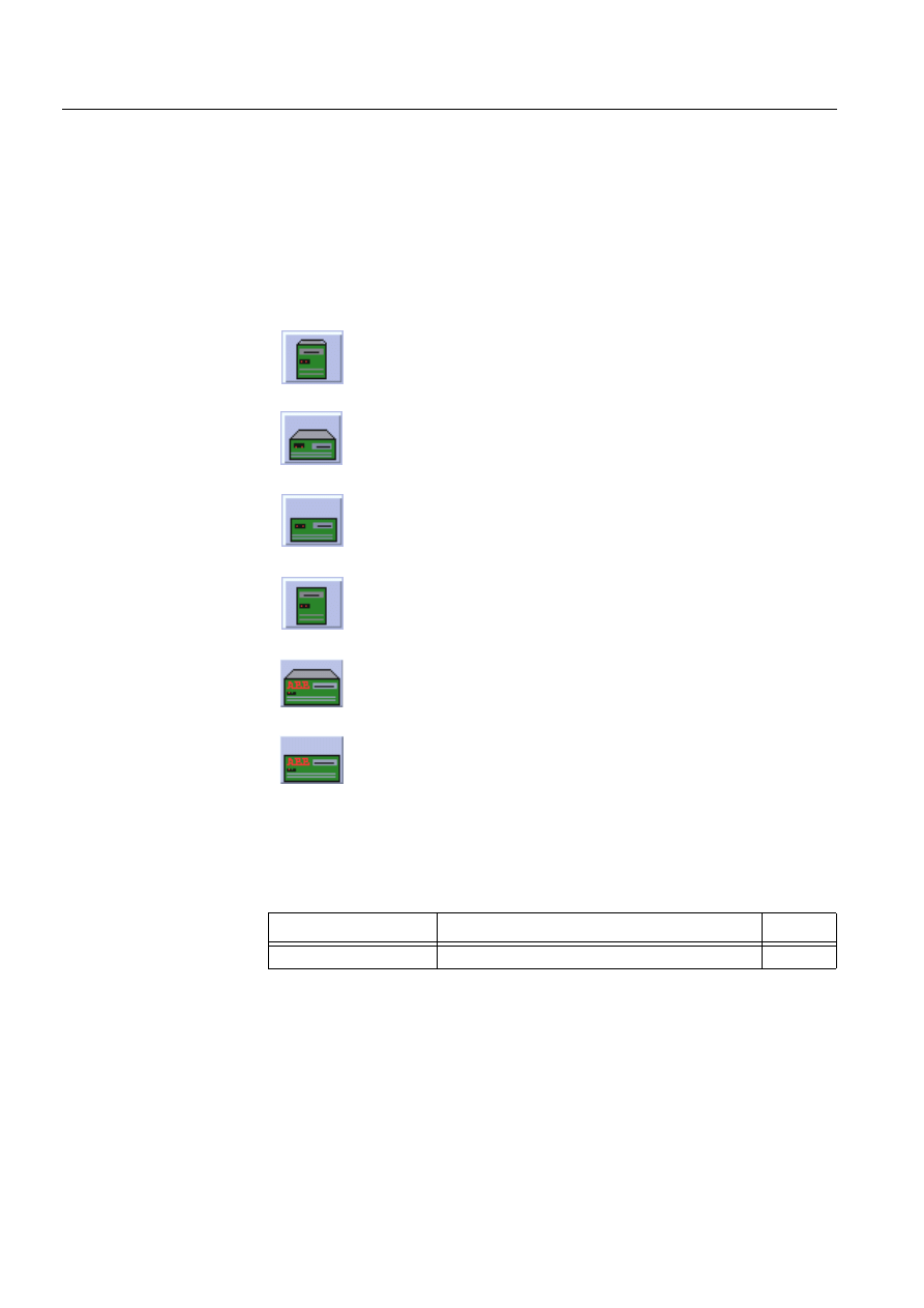
188
1MRS751880-MEN
LIB 500 Configuration Manual
LIB 500
8. System self supervision Configuration Guide
8.7.4.2.
Installation
There are two different sizes of the base system picture function: medium (3*2) and
large (5*3). The size of the medium base system picture function is 48 x 40 pixels
(3 x 2 semigraphical blocks) and the large picture function is 80 x 60 pixels (5 x 3
semigraphical blocks). The button frame is drawn out of this area.
(see Fig. 8.7.4.2.-1) presents all different types of base system picture function in
typical installations.
)LJ ,QVWDOODWLRQIRUEDVHV\VWHPSLFWXUHIXQFWLRQ
During the installation, the following information has to be given:
Table 8.7.4.2-1
Installation information
8.7.4.3.
Picture function configuration
Preliminary work
Before the configuration of the picture functions can start, some preparatory
configurations are required (i.e. configuration that are required only once). The
usage of the Object Identification (OI) -attribute has to be settled and the translation
B1.tif
Tower model medium size (3-D)
B2.tif
Desktop medium size (3-D)
B3.tif
Desktop medium size
B4.tif
Tower model medium size
BL1.tif
Desktop large size (3-D)
BL2.tif
Desktop large size
Attribute
Meaning
Default
Picture function name
Name of the picture function within the picture
-

1MRS751880-MEN
LIB 500
189
LIB 500 Configuration Manual
Configuration Guide
8. System self supervision
8
of the signal texts into the local language has to be performed. Please refer to the
Section 8.3.2 for further information.
Please notify that the process objects of the base system picture function are created
automatically in the background either as the Supervision Base functionality is
installed or as the picture function is configured. Thus, no preliminary work for the
process objects is required. However, it is necessary to know how the system is
configured (application and node numbers etc.).
Configuration with Standard Configuration Tool
The base system picture function has the following attributes to configure with the
Standard Configuration Tool.
Table 8.7.4.3-1
The attributes of the base system picture function to
configure with the Standard Configuration Tool
Attribute
Meaning
Default
AUTHORIZATION_GROUP
The name of the authorization group
SUPERVISION
LABEL
The abbreviation of the supervised
picture to be shown in the system
supervision picture.
-
LABEL_POSITION
Position of the label
TOP
APL_NUMBERS
A vector type of an element, containing
the physical numbers of the supervised
applications.
APL:BNA
HOT_STAND_BY
Indicates whether the system is a single
or a hot stand-by (warm-stand by)
system
FALSE
NODE_NUMBER
The node number of the base system
containing the supervised application
SYS:BND
EXT_WD_APL_NR
The logical number of the watch dog
application in the "remote" (i.e. other
than the current) base system,
"adjacent watch dog".
0
WRITE_DEVICE_INFO
(in Programs folder)
An optional program by which three (3)
lines of device information are written to
the picture function. The maximum
length of each line is 28 characters.

190
1MRS751880-MEN
LIB 500 Configuration Manual
LIB 500
8. System self supervision Configuration Guide
Configuration with Representation Tool
The base system picture function has the following attributes to configure with the
Representation Tool (Refer to the Section 8.5.2 for further details):
Attribute
Meaning
AUTHORIZATION_GROUP
A selector type of an editable combo box to select the
authorization group for the object. The maximum length of
the text is 63 characters. The given text has to be usable as
a SCIL list attribute name (see the manual Programming
Language SCIL, 1MRS751849-MEN). The contents of the
selection list is taken from the existing authorization groups.
NOTE! The name may not be composed of two letters
followed by a number.
The attribute needs to be defined, if the object is wanted to
be included in some authorization group. The authorization
level of each user in this group can be defined afterwards by
the system manager with the User Management pictures.
LABEL
A text which will be placed outside the picture function
symbol as the picture is opened to the monitor. The position
of the text is determined by the LABEL_POSITION. The
maximum length of the LABEL is 15 characters.
LABEL_POSITION
A selector type of a combo box to select the position for the
LABEL text.
Valid values: "TOP", "BOTTOM", "LEFT" or "RIGHT"
APL_NUMBERS
A vector type of an element, containing the physical
numbers of the supervised applications.
Valid numbers: 1..99
NOTE! By default the current application number is
displayed.
If the application is situated in another base system
computer (APL<apl.number>:BTT = "EXTERNAL"), the
state of the application is read from the "remote" base
system.
HOT_STAND_BY
Indicates whether the system is a single or a hot stand-by
(warm-stand by) system. If the HOT_STAND_BY is enabled,
the following attributes are enabled:
- NODE_NUMBER
- EXT_WD_APL_NR
NODE_NUMBER
The node number of the base system containing the
supervised application. If the node number is other than the
current node (SYS:BSD), the state of the application is read
via the watch dog application of the "remote" base system.
Valid numbers: 1..20.
The configurable attribute is significant only in hot stand-by
(warm stand-by) systems.
NOTE! By default the current node is displayed.
EXT_WD_APL_NR
The logical number of the watch dog application in the
"remote" (i.e. other than the current) base system, "adjacent
watch dog".
Valid numbers: 1..99.
The configurable attribute is significant only in hot stand-by
(warm stand-by) systems.
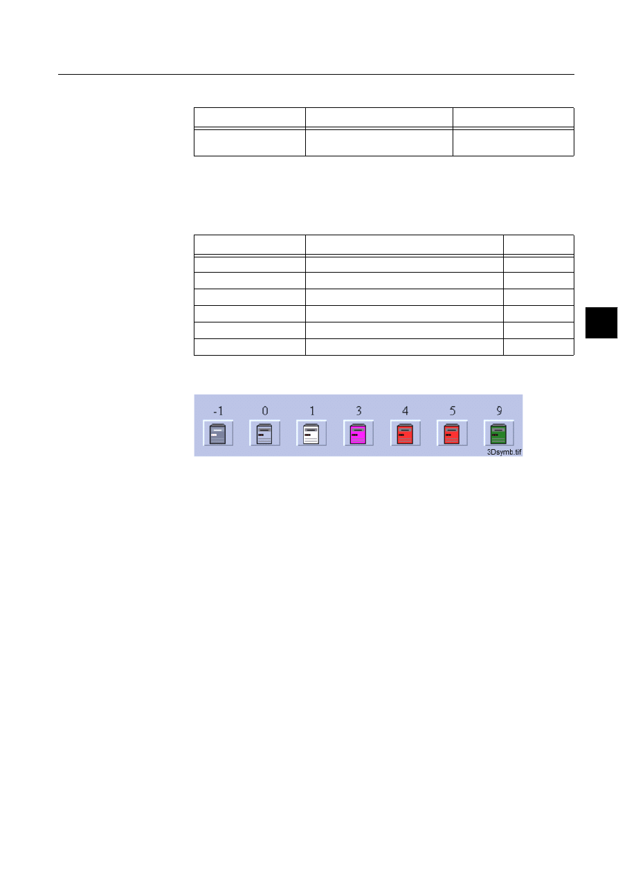
1MRS751880-MEN
LIB 500
191
LIB 500 Configuration Manual
Configuration Guide
8. System self supervision
8
Table 8.7.4.3-2
The attributes of the base system picture function to
configure with the Representation Tool
By default, there are four sets of symbols in two different sizes. Example of these
default presentations is shown below as medium sized. Please note that in actual
system the symbol representing the selector 3 is flashing to draw attention.
Table 8.7.4.3-3
Symbol presentations
(see Fig. 8.7.4.3.-1) presents tower model symbols (3-D) for the base system.
)LJ 7RZHUPRGHOV\PERO'IRUWKHEDVHV\VWHP
8.7.4.4.
Configuration with Process Object Tool
The monitor picture function has no attributes to configure with the Process Object
Tool.
Attribute
Meaning
Default
REPRESENTATION
Selection of symbol set shown in
picture
B_REPR/B_CPU1 or
B_REPR/B_CPUL1
Symbol
Representation
Size
B_REPR/B_CPU1
Tower model (3-D)
Medium
B_REPR/B_CPU2
Desktop (3-D)
Medium
B_REPR/B_CPU3
Desktop
Medium
B_REPR/B_CPU4
Tower model
Medium
B_REPR/B_CPUL1
Desktop (3-D)
Large
B_REPR/B_CPUL2
Desktop
Large
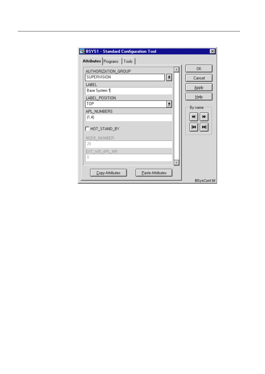
192
1MRS751880-MEN
LIB 500 Configuration Manual
LIB 500
8. System self supervision Configuration Guide
8.7.4.5.
An example of a base system configuration
)LJ $QH[DPSOHRIWKHFRQILJXUDWLRQRIWKHEDVHV\VWHPSLFWXUHIXQFWLRQ
8.7.4.6.
Information dialogs
As the base system object is being configured, the Information dialogs may be
displayed in case the system configuration does not exist or the system configuration
includes attribute value definitions that do not allow all the diagnostic available for
the System Self Supervision. More information can be found in the Section 8.5.4.
8.7.5.
Application engineering information
8.7.5.1.
The structure of the base system picture function
This chapter describes the structure of the base system picture function. All pictures,
form pictures, help and other text files as well as all database objects are included.
The base system picture function is a part of the System Self Supervision of LIB 500
and has a directory /LIB4/BASE/SYSTEM/, and the standard LIB 500 sub-
directories INST/, LANG0 and USE.
The installation of the “instance” picture function will automatically install “type”
picture function (BSI_SYST) if it does not already exist. The “type” picture function
contains all common programs for the “instance” picture function and it is only
visible at the Picture Editor.

1MRS751880-MEN
LIB 500
193
LIB 500 Configuration Manual
Configuration Guide
8. System self supervision
8
8.7.5.2.
Pictures
Below there is a list of all base system pictures and a short description of their
functionality. Dialogs are described in detail in the LIB 500 Operator’s Manual,
1MRS751885-MUM (Chapter 6). The paths are
/LIB4/BASE/SYSTEM/INST/
Table 8.7.5.2-1
A list of the base system pictures and description of their
functionality (first path)
and /LIB4/BASE/SYSTEM/USE/
Table 8.7.5.2-2
A list of the base system pictures and description of their
functionality (second path)
8.7.5.3.
Help text files
Below there is a list of the base system help text files. The path is
/LIB4/BASE/SYSTEM/LANG0/
Table 8.7.5.3-1
A list of the base system help text files
8.7.5.4.
Configuration files
The following configuration files are used by the base system picture function. The
path is
LIB4/BASE/SYSTEM/INST/
Table 8.7.5.4-1
The configuration files used by the base system picture
function
Picture
Functionality
BSI_SYSTT.PIC
Common programs for all base system picture functions
BSI_SYSI_M.PIC
Medium picture function (3*2) for base system object
BSI_SYSI_L.PIC
Large picture function (5*3) for base system object
Picture
Functionality
BSU_DLG2A.PIC
Main dialog
BSU_DLGB.PIC
Device information dialog (common for all other picture
functions, too).
Help file
Functionality
BSI_SYS2.HLP
Picture function installation help file
BSU_SYS2.HLP
Main dialog help file
Configuration file
Functionality
BSI_SYS2.DAT
Contains the configuration data for base system object when
it is created, modified or deleted by configuration tools.
INDEX4_B11.TXT
Selection list of LIB 500 Rev 4.0.3 System Self Supervision
picture functions for installation tool (common for all other
picture functions, too).

194
1MRS751880-MEN
LIB 500 Configuration Manual
LIB 500
8. System self supervision Configuration Guide
8.7.5.5.
Other text files
The following text files are used by the base system. The path is
/LIB4/BASE/SYSTEM/USE/
Table 8.7.5.5-1
The text files used by the base system
8.7.5.6.
System configuration
The operation of the base system object is based on the predefined events generated
by the SYS_EVENT. Thus, in order for the base system object to work properly,
system events must be enabled for the current application. Refer to the Section
8.3.1.1 for detailed information.
8.7.5.7.
Process objects
The database objects related to the base system object are created automatically
either in background as OK or Apply button is being clicked or by the use of System
Configuration Tool. More information can be found in the Section 8.3.4.7.
The following process objects are created:
Table 8.7.5.7-1
Local applications
Table 8.7.5.7-2
External applications
8.7.5.8.
Scale objects
At first installation, the base system object creates the scale 1_1 (linear 1:1 scale) if
the scale 1_1 does not exist.
Text file
Functionality
PATH4_B11.TXT
Contains the path definitions for the System Self Supervision
(common for all other picture functions, too).
Index
Obj. type
Process object
Remarks
Group identifier
10
AI
Application state
-
BSWAPLIAPL
20
AI
Application shadowing
phase
-
BSWAPLIAPL
30
BI
Application local memory
pools state
-
BSWAPLIAPL
40
BI
Application local queues
state
-
BSWAPLIAPL
10
BI
Global memory pool state
of MicroSCADA base
system
-
BSWSYSISYS
Index
Obj. type
Process object
Remarks
Group identifier
11
AI
Application state
-
BSWAPLIAPL
21
AI
Application shadowing
phase
-
BSWAPLIAPL

1MRS751880-MEN
LIB 500
195
LIB 500 Configuration Manual
Configuration Guide
8. System self supervision
8
8.7.5.9.
Command procedures
At first installation, the base system object creates the following command
procedures if the supervised applications include external applications or there is a
hot-stand-by (warm-stand-by) system in question.
Table 8.7.5.9-1
Command Procedures
8.7.5.10.
Time channels
At first installation, the base system object creates the following time channels if the
supervised applications include external applications or there is a hot-stand-by
(warm-stand-by) system in question.
Table 8.7.5.10-1 Time Channels
8.7.5.11.
Event channels
At first installation, the base system object creates the event channel SYS_EVENT,
if it does not exist.
8.8.
Application
8.8.1.
Target systems
MicroSCADA systems, especially system supervision pictures.
8.8.2.
Application support
• Local applications (in a single or in a hot-stand-by system)
• External applications (in a single system)
Command
procedure
Functionality
Remarks
SYS_APLE1
Command procedure for application supervision In case of
external
application
SYS_APLE2
Command procedure for application supervision In case of
external
application
SYS_APLH1
Command procedure for application supervision In case of hot-
stand-by system
SYS_APLH2
Command procedure for application supervision In case of hot-
stand-by system
Time Channel
Functionality
Remarks
SYS_APLE
Time channel for application supervision
In case of
external
application
SYS_APLH
Time channel for application supervision
In case of hot-
stand-by system

196
1MRS751880-MEN
LIB 500 Configuration Manual
LIB 500
8. System self supervision Configuration Guide
8.8.3.
Features/options
• Versatile configuration
• Device information
• Help in all dialogs
8.8.4.
Picture function installation
This chapter describes the installation of picture functions for the System Self
Supervision application object. The picture function for the application is found in
the directory /LIB4/BASE/SYSTEM/INST/ and it should be installed by using LIB4
installation procedures (LIB4 - LIB 500 - Supervision 2.x – Application). This
picture function is configured by using standard configuration tools such as:
1. Standard Configuration Tool and
2. Representation Tool
8.8.4.1.
Environmental requirements
In order for the application to have full functionality, the following component needs
to be installed first:
• Base for 4.0.3
8.8.4.2.
Installation
The size of the application picture function is 96 x 40 pixels (6 x 2 semigraphical
blocks). The button frame is drawn out of this area.
(see Fig. 8.8.4.2.-1) presents the application picture function in a typical installation.
)LJ ,QVWDOODWLRQIRUDSSOLFDWLRQSLFWXUHIXQFWLRQ
During the installation, the following information has to be given:
Table 8.8.4.2-1
Installation information
8.8.4.3.
Picture function configuration
Preliminary work
Before the configuration of the picture functions can start, some preparatory
configurations are required (i.e. configuration that are required only once). The
usage of the Object Identification (OI) -attribute has to be settled and the translation
of the signal texts into the local language has to be performed. Please refer to Section
8.3.2 for further information.
Apl.tif
Attribute
Meaning
Default
Picture function name
Name of the picture function within the picture
-

1MRS751880-MEN
LIB 500
197
LIB 500 Configuration Manual
Configuration Guide
8. System self supervision
8
Please notify that the process objects of the application picture function are created
automatically in the background either as the Supervision Base functionality is
installed or as the picture function is configured. Thus, no preliminary work for the
process objects is required. However, it is necessary to know how the system is
configured (application and node numbers etc.).
Configuration with Standard Configuration Tool
The application picture function has the following attributes to configure with the
Standard Configuration Tool.
Table 8.8.4.3-1
The attributes of the application picture function to
configure with the Standard Configuration Tool.
Attribute
Meaning
Default
AUTHORIZATION_GROUP
The name of the authorization group
SUPERVISION
APL_NUMBER
The physical number of the supervised
applications.
APL:BAN
APL_INFO
Indicates whether the application
information is enabled/disabled.
TRUE
APL_INFO_POSITION
Position of the application information
RIGHT
HOT_STAND_BY
Indicates whether the system is a single
or a hot stand-by (warm-stand by)
system
FALSE
NODE_NUMBER
The node number of the MicroSCADA
base system containing the supervised
application
SYS:BND
EXT_WD_APL_NR
The logical number of the watch dog
application in the "remote" (i.e. other
than the current) base system,
"adjacent watch dog".
0
WRITE_DEVICE_INFO
(in Programs folder)
An optional program by which three (3)
lines of device information are written to
the picture function. The maximum
length of each line is 28 characters.

198
1MRS751880-MEN
LIB 500 Configuration Manual
LIB 500
8. System self supervision Configuration Guide
Attribute
Meaning
AUTHORIZATION_GROUP
A selector type of an editable combo box to select the
authorization group for the object. The maximum length of
the text is 63 characters. The given text has to be usable as
a SCIL list attribute name (see the manual Programming
Language SCIL, 1MRS751849-MEN). The contents of the
selection list is taken from the existing authorization groups.
NOTE! The name may not be composed of two letters
followed by a number.
The attribute needs to be defined, if the object is wanted to
be included in some authorization group. The authorization
level of each user in this group can be defined afterwards by
the system manager with the User Management pictures.
APL_NUMBER
The physical number of the supervised application.
Valid numbers: 1..99
NOTE! By default the current application number is
displayed.
If the application is situated in another base system
computer (APL<apl.number>:BTT = "EXTERNAL"), the
state of the application is read from the "remote" base
system.
APL_INFO
Indicates whether the application information is enabled/
disabled. If the application information is enabled, the
current application state and shadowing phase (in case of a
hot stand-by system) is shown beside the application object.
The position of the application information is determined by
the APL_INFO_POSITION.
APL_INFO_POSITION
A selector type of a combo box to select the position for the
application information text.
Valid values: "LEFT" or "RIGHT".
If the APL_INFO is disabled, the configurable attribute is
being disabled, and the value has no meaning.
HOT_STAND_BY
Indicates whether the system is a single or a hot stand-by
(warm-stand by) system. If the HOT_STAND_BY is enabled,
the following attributes are enabled:
- NODE_NUMBER
- EXT_WD_APL_NR
NODE_NUMBER
The node number of the base system containing the
supervised application. If the node number is other than the
current node (SYS:BSD), the state of the application is read
via the watch dog application of the "remote" base system.
Valid numbers: 1..20.
The configurable attribute is significant only in hot stand-by
(warm stand-by) systems.
NOTE! By default the current node is displayed.
EXT_WD_APL_NR
The logical number of the watch dog application in the
"remote" (i.e. other than the current) base system, "adjacent
watch dog".
Valid numbers: 1..99.
The configurable attribute is significant only in hot stand-by
(warm stand-by) systems.
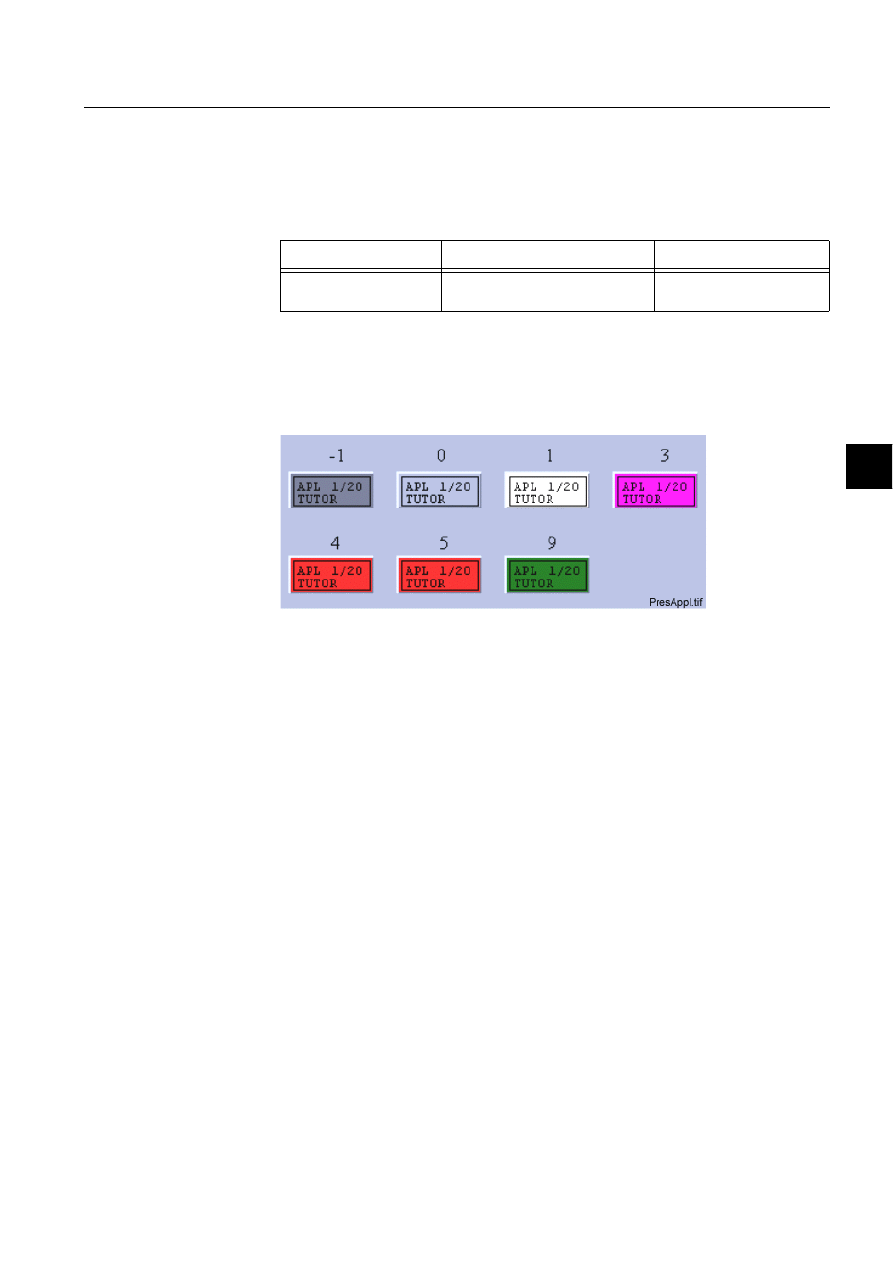
1MRS751880-MEN
LIB 500
199
LIB 500 Configuration Manual
Configuration Guide
8. System self supervision
8
Configuration with Representation Tool
The application picture function has the following attributes to configure with the
Representation Tool (Refer to the Section 8.5.2 for further details):
Table 8.8.4.3-2
The attributes of the application picture function to
configure with the Representation Tool.
By default, there is one set of symbols in one size. This default presentation is shown
below. Please note that in actual system the symbol representing the selector 3 is
flashing to draw attention.
(see Fig. 8.8.4.3.-1) presents application symbols for application.
)LJ 3UHVHQWDWLRQIRUWKHDSSOLFDWLRQ
8.8.4.4.
Configuration with Process Object Tool
The application picture function has no attributes to configure with the Process
Object Tool.
Attribute
Meaning
Default
REPRESENTATION
Selection of symbol set shown in
picture
B_REPR/B_APL
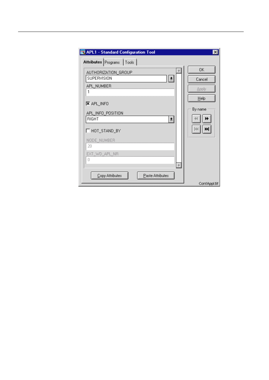
200
1MRS751880-MEN
LIB 500 Configuration Manual
LIB 500
8. System self supervision Configuration Guide
8.8.4.5.
An example of application configuration
)LJ $QH[DPSOHRIWKHFRQILJXUDWLRQRIWKHDSSOLFDWLRQSLFWXUHIXQFWLRQ
8.8.4.6.
Information dialogs
As the application object is being configured, the Information dialogs may be
displayed in case the system configuration does not exist or the system configuration
includes attribute value definitions that do not allow all the diagnostic available for
the System Self Supervision. More information can be found in the Section 8.5.4.
8.8.5.
Application engineering information
8.8.5.1.
The structure of the application picture function
This chapter describes the structure of the application picture function. All pictures,
form pictures, help and other text files as well as all database objects are included.
The application picture function is a part of the System Self Supervision of LIB 500
and has a directory /LIB4/BASE/SYSTEM/, and the standard LIB 500 sub-
directories INST, LANG0 and USE.
The installation of the “instance” picture function will automatically install “type”
picture function (BSI_APLT) if it does not already exist. The “type” picture function
contains all common programs for the “instance” picture function and it is only
visible at the Picture Editor.

1MRS751880-MEN
LIB 500
201
LIB 500 Configuration Manual
Configuration Guide
8. System self supervision
8
8.8.5.2.
Pictures
Below there is a list of all application pictures and a short description of their
functionality. Dialogs are described in detail in the LIB 500 Operator’s Manual,
1MRS751885-MUM (Chapter 6). The paths are
/LIB4/BASE/SYSTEM/INST/
Table 8.8.5.2-1
A list of the application pictures and description of their
functionality (first path)
and /LIB4/BASE/SYSTEM/USE/
Table 8.8.5.2-2
A list of the application pictures and description of their
functionality (second path)
8.8.5.3.
Help text files
Below there is a list of the application help text files. The path is /LIB4/BASE/
SYSTEM/LANG0.
Table 8.8.5.3-1
A list of the application help text files
8.8.5.4.
Configuration files
The following configuration files are used by the application picture function. The
path is
LIB4/BASE/SYSTEM/INST/
Table 8.8.5.4-1
The configuration files used by the application picture
function
Picture
Functionality
BSI_APLT.PIC
Common programs for all application picture functions
BSI_APLI.PIC
Picture function (6*2) for application object
Picture
Functionality
BSU_DLGA.PIC
Main dialog (common for all other picture functions, too).
BSU_DLGB.PIC
Device information dialog (common for all other picture
functions, too).
Help file
Functionality
BSI_APL.HLP
Picture function installation help file
BSU_APL.HLP
Main dialog help file
Configuration file
Functionality
BSI_APL.DAT
Contains the configuration data for application object when it
is created, modified or deleted by configuration tools.
INDEX4_B11.TXT
Selection list of LIB 500 Rev 4.0.3 System Self Supervision
picture functions for installation tool (common for all other
picture functions, too).

202
1MRS751880-MEN
LIB 500 Configuration Manual
LIB 500
8. System self supervision Configuration Guide
8.8.5.5.
Other text files
The following text files are used by the application. The path is
/LIB4/BASE/SYSTEM/USE/.
Table 8.8.5.5-1
The text files used by the application
8.8.5.6.
System configuration
The operation of the application object is based on the predefined events generated
by the SYS_EVENT. Thus, in order for the application object to work properly,
system events must be enabled for the current application. Refer to the Section
8.3.1.1 for detailed information.
8.8.5.7.
Process objects
The database objects related to the application object are created automatically
either in background as OK or Apply button is being clicked or by the use of System
Configuration Tool. More information can be found in the Section 8.3.4.7.
The following process objects are created:
Table 8.8.5.7-1
Local application
Table 8.8.5.7-2
External application
8.8.5.8.
Scale objects
At first installation, the application object creates the scale 1_1 (linear 1:1 scale) if
the scale 1_1 does not exist.
Text file
Functionality
PATH4_B11.TXT
Contains the path definitions for the System Self Supervision
(common for all other picture functions, too).
Index
Obj. type
Process object
Remarks
Group identifier
10
AI
Application state
-
BSWAPLIAPL
20
AI
Application shadowing
phase
-
BSWAPLIAPL
30
BI
Application local memory
pools state
-
BSWAPLIAPL
40
BI
Application local queues
state
-
BSWAPLIAPL
10
BI
Global memory pool state
of MicroSCADA base
system
-
BSWSYSISYS
Index
Obj. type
Process object
Remarks
Group identifier
11
AI
Application state
-
BSWAPLIAPL
21
AI
Application shadowing
phase
-
BSWAPLIAPL

1MRS751880-MEN
LIB 500
203
LIB 500 Configuration Manual
Configuration Guide
8. System self supervision
8
8.8.5.9.
Command procedures
At first installation, the application object creates the following command
procedures if the supervised application refers to an external applications or there is
a hot-stand-by (warm-stand-by) system in question.
Table 8.8.5.9-1
Command Procedures
8.8.5.10.
Time channels
At first installation, the application object creates the following time channels if the
supervised application refers to an external application or there is a hot-stand-by
(warm-stand-by) system in question.
Table 8.8.5.10-1 Time Channels
8.8.5.11.
Event channels
At first installation, the application object creates the event channel SYS_EVENT,
if it does not exist.
8.9.
Communication unit
8.9.1.
Target systems
MicroSCADA systems, especially system supervision pictures.
8.9.2.
Communication unit support
• PC-NET
• DCP-NET
• MFL
8.9.3.
Features/options
• Versatile configuration
Command
procedure
Functionality
Remarks
SYS_APLE1
Command procedure for application
supervision
In case of external
application
SYS_APLE2
Command procedure for application
supervision
In case of external
application
SYS_APLH1
Command procedure for application
supervision
In case of hot-stand-by
system
SYS_APLH2
Command procedure for application
supervision
In case of hot-stand-by
system
Time Channel
Functionality
Remarks
SYS_APLE
Time channel for application supervision
In case of external
application
SYS_APLH
Time channel for application supervision
In case of hot-stand-by
system

204
1MRS751880-MEN
LIB 500 Configuration Manual
LIB 500
8. System self supervision Configuration Guide
• Device information
• Help in all dialogs
8.9.4.
Picture function installation
This chapter describes the installation of picture functions for the System Self
Supervision communication unit (NET) object. The picture function for the
communication unit (NET) is found in the directory /LIB4/BASE/SYSTEM/INST/
and it should be installed by using LIB4 installation procedures (LIB4 - LIB 500 -
Supervision 2.x – NET). This picture function is configured by using standard
configuration tools such as:
1. Standard Configuration Tool and
2. Representation Tool
8.9.4.1.
Environmental requirements
In order for the communication unit to have full functionality, the following
component needs to be installed first:
• Base for 4.0.3
8.9.4.2.
Installation
There are two different sizes of the communication unit picture function: medium
(3*2) and large (5*2). The size of the medium communication unit picture function
is 48 x 40 pixels (3 x 2 semigraphical blocks) and the large picture function is 80 x
40 pixels (5 x 2 semigraphical blocks). The button frame is drawn out of this area.
(see Fig. 8.9.4.2.-1) presents a communication unit object as in typical installations.
)LJ ,QVWDOODWLRQIRUFRPPXQLFDWLRQXQLWSLFWXUHIXQFWLRQ
During the installation, the following information has to be given:
N1.tif
PC-NET
N2.tif
DCP-NET
N3.tif
MFL

1MRS751880-MEN
LIB 500
205
LIB 500 Configuration Manual
Configuration Guide
8. System self supervision
8
Table 8.9.4.2-1
Installation information
8.9.4.3.
Picture function configuration
Preliminary work
Before the configuration of the picture functions can start, some preparatory
configurations are required (i.e. configuration that are required only once). The
usage of the Object Identification (OI) -attribute has to be settled and the translation
of the signal texts into the local language has to be performed. Please refer to Section
8.3.2 for further information.
Please notify that the process objects of the communication unit picture function are
created automatically in the background either as the Supervision Base functionality
is installed or as the picture function is configured. Thus, no preliminary work for
the process objects is required. However, it is necessary to know how the system is
configured (node number, type of communication unit etc.).
Configuration with Standard Configuration Tool
The communication unit picture function has the following attributes to configure
with the Standard Configuration Tool.
Table 8.9.4.3-1
The attributes of the communication unit picture function to
configure with the Standard Configuration Tool.
Attribute
Meaning
Default
Picture function name
Name of the picture function within the picture
-
Attribute
Meaning
Default
AUTHORIZATION_GROUP
The name of the authorization group
SUPERVISION
LABEL
The abbreviation of the supervised
picture to be shown in the system
supervision picture.
-
LABEL_POSITION
Position of the label
TOP
NET_NODE_NR
The node number of the communication
unit (NET).
SYS:BDN
NET_TYPE
The type of NET (PC-NET, DCP-NET,
MFL)
PC-NET
REDUNDANCY
Indicates whether the communication
unit (NET) is single or redundant in case
the type of the supervised
communication unit (NET) is MFL
Single
PEER_NODE_NR
The node number of the peer
communication unit (NET) in the
redundant relation
0

206
1MRS751880-MEN
LIB 500 Configuration Manual
LIB 500
8. System self supervision Configuration Guide
REDUNDANCY_INFO
Indicates whether the redundancy
information is enabled/disabled.
FALSE
REDUNDANCY_INFO_
POSITION
A selector type of a combo box to select
the position for the redundancy
information text.
LEFT
U_WRITE_DEVICE_INFO
( in Programs folder)
An optional program by which three (3)
lines of device information are written to
the picture function. The maximum
length of each line is 28 characters.
Attribute
Meaning
Default
Attribute
Meaning
AUTHORIZATION_GROUP
A selector type of an editable combo box to select the
authorization group for the object. The maximum length of
the text is 63 characters. The given text has to be usable as
a SCIL list attribute name (see the manual Programming
Language SCIL, 1MRS751849-MEN). The contents of the
selection list is taken from the existing authorization groups.
NOTE! The name may not be composed of two letters
followed by a number.
The attribute needs to be defined, if the object is wanted to
be included in some authorization group. The authorization
level of each user in this group can be defined afterwards by
the system manager with the User Management pictures.
LABEL
A text which will be placed outside the picture function
symbol as the picture is opened to the monitor. The position
of the text is determined by the LABEL_POSITION. The
maximum length of the LABEL is 15 characters.
LABEL_POSITION
A selector type of a combo box to select the position for the
LABEL text.
Valid values: "TOP", "BOTTOM", "LEFT" or"RIGHT"
NET_NODE_NR
The node number of the supervised communication unit
(NET).
Valid values: 1..20.
NOTE! By default the node number of the NET unit that will
be regarded as default NET unit (SYS:BDN) will be
displayed.
NET_TYPE
The type of the supervised communication unit (NET).
Valid values: "PC-NET", "DCP-NET" or "MFL".
Default value: "PC-NET"
REDUNDANCY
Indicates whether the communication unit (NET) is single or
redundant in case the type of the supervised communication
unit (NET) is MFL.
Valid values: "Single" or "Redundant".
Default value: "Single".
If the REDUNDANCY is set as "Redundant", the following
attributes are enabled:
- PEER_NODE_NR
- REDUNDANCY_INFO
- REDUNDANCY_INFO_POSITION

1MRS751880-MEN
LIB 500
207
LIB 500 Configuration Manual
Configuration Guide
8. System self supervision
8
Configuration with Representation Tool
The communication unit picture function has the following attributes to configure
with the Representation Tool (Refer to the Section 8.5.2 for further details):
Table 8.9.4.3-2
The attributes of the communication unit picture function to
configure with the Representation Tool.
By default, there are eight sets of symbols in two different sizes for each
communication unit type separately. Example of these default presentations is
shown below as medium sized. Please note that in actual system the symbol
representing the selector 3 is flashing to draw attention.
Table 8.9.4.3-3
Symbol presentations
PEER_NODE_NR
The node number of the peer communication unit (NET) in
the redundant relation (i.e. the number of another redundant
NET unit).
Valid numbers: 0..32, 0 = no redundancy.
The configurable attribute is significant only in case of a
redundant NET unit.
NOTE! By default the node number of the peer
communication unit (NET) is read from the system
configuration. If reading is successful (i.e. system
configuration for the specified communication unit exists),
the configurable attribute is disabled regardless of the
REDUNDANCY value.
REDUNDANCY_INFO
Indicates whether the redundancy information is enabled/
disabled.If the redundancy information is enabled, the
current redundancy mode and shadowing state of the
redundant NET unit is shown beside the NET object. The
position of the redundancy information is determined by the
REDUNDANCY_INFO_POSITION.
REDUNDANCY_INFO_
POSITION
A selector type of a combo box to select the position for the
redundancy information text.
Valid values: "LEFT" and "RIGHT".
If the REDUNDANCY_INFO is disabled, the configurable
attribute is being disabled, and the value has no meaning,
regardless of the REDUNDANCY value. The configurable
attribute is significant only in case of a redundant NET unit.
Attribute
Meaning
Attribute
Meaning
Default
REPRESENTATION
Selection of symbol set shown in
picture
B_REPR/B_PCN8 or
B_REPR/B_PCNL8
Symbol
Representation
Size
B_REPR/B_PCN1
PC-NET symbol with 1 line drawn
Medium
B_REPR/B_PCN2
PC-NET symbol with 2 lines drawn
Medium
B_REPR/B_PCN3
PC-NET symbol with 3 lines drawn
Medium
B_REPR/B_PCN4
PC-NET symbol with 4 lines drawn
Medium
B_REPR/B_PCN5
PC-NET symbol with 5 lines drawn
Medium
B_REPR/B_PCN6
PC-NET symbol with 6 lines drawn
Medium

208
1MRS751880-MEN
LIB 500 Configuration Manual
LIB 500
8. System self supervision Configuration Guide
B_REPR/B_PCN7
PC-NET symbol with 7 lines drawn
Medium
B_REPR/B_PCN8
PC-NET symbol with 8 lines drawn
Medium
B_REPR/B_DCP1
DCP-NET symbol with 1 line drawn
Medium
B_REPR/B_DCP2
DCP-NET symbol with 2 lines drawn
Medium
B_REPR/B_DCP3
DCP-NET symbol with 3 lines drawn
Medium
B_REPR/B_DCP4
DCP-NET symbol with 4 lines drawn
Medium
B_REPR/B_DCP5
DCP-NET symbol with 5 lines drawn
Medium
B_REPR/B_DCP6
DCP-NET symbol with 6 lines drawn
Medium
B_REPR/B_DCP7
DCP-NET symbol with 7 lines drawn
Medium
B_REPR/B_DCP8
DCP-NET symbol with 8 lines drawn
Medium
B_REPR/B_MFL1
MFL-NET symbol with 1 line drawn
Medium
B_REPR/B_MFL2
MFL-NET symbol with 2 lines drawn
Medium
B_REPR/B_MFL3
MFL-NET symbol with 3 lines drawn
Medium
B_REPR/B_MFL4
MFL-NET symbol with 4 lines drawn
Medium
B_REPR/B_MFL5
MFL-NET symbol with 5 lines drawn
Medium
B_REPR/B_MFL6
MFL-NET symbol with 6 lines drawn
Medium
B_REPR/B_MFL7
MFL-NET symbol with 7 lines drawn
Medium
B_REPR/B_MFL8
MFL-NET symbol with 8 lines drawn
Medium
B_REPR/B_PCNL1
PC-NET symbol with 1 line drawn
Large
B_REPR/B_PCNL2
PC-NET symbol with 2 lines drawn
Large
B_REPR/B_PCNL3
PC-NET symbol with 3 lines drawn
Large
B_REPR/B_PCNL4
PC-NET symbol with 4 lines drawn
Large
B_REPR/B_PCNL5
PC-NET symbol with 5 lines drawn
Large
B_REPR/B_PCNL6
PC-NET symbol with 6 lines drawn
Large
B_REPR/B_PCNL7
PC-NET symbol with 7 lines drawn
Large
B_REPR/B_PCNL8
PC-NET symbol with 8 lines drawn
Large
B_REPR/B_DCPL1
DCP-NET symbol with 1 line drawn
Large
B_REPR/B_DCPL2
DCP-NET symbol with 2 lines drawn
Large
B_REPR/B_DCPL3
DCP-NET symbol with 3 lines drawn
Large
B_REPR/B_DCPL4
DCP-NET symbol with 4 lines drawn
Large
B_REPR/B_DCPL5
DCP-NET symbol with 5 lines drawn
Large
B_REPR/B_DCPL6
DCP-NET symbol with 6 lines drawn
Large
B_REPR/B_DCPL7
DCP-NET symbol with 7 lines drawn
Large
B_REPR/B_DCPL8
DCP-NET symbol with 8 lines drawn
Large
B_REPR/B_MFLL1
MFL-NET symbol with 1 line drawn
Large
B_REPR/B_MFLL2
MFL-NET symbol with 2 lines drawn
Large
B_REPR/B_MFLL3
MFL-NET symbol with 3 lines drawn
Large
B_REPR/B_MFLL4
MFL-NET symbol with 4 lines drawn
Large
B_REPR/B_MFLL5
MFL-NET symbol with 5 lines drawn
Large
Symbol
Representation
Size

1MRS751880-MEN
LIB 500
209
LIB 500 Configuration Manual
Configuration Guide
8. System self supervision
8
B_REPR/B_PCN7
PC-NET symbol with 7 lines drawn
Medium
B_REPR/B_PCN8
PC-NET symbol with 8 lines drawn
Medium
B_REPR/B_DCP1
DCP-NET symbol with 1 line drawn
Medium
B_REPR/B_DCP2
DCP-NET symbol with 2 lines drawn
Medium
B_REPR/B_DCP3
DCP-NET symbol with 3 lines drawn
Medium
B_REPR/B_DCP4
DCP-NET symbol with 4 lines drawn
Medium
B_REPR/B_DCP5
DCP-NET symbol with 5 lines drawn
Medium
B_REPR/B_DCP6
DCP-NET symbol with 6 lines drawn
Medium
B_REPR/B_DCP7
DCP-NET symbol with 7 lines drawn
Medium
B_REPR/B_DCP8
DCP-NET symbol with 8 lines drawn
Medium
B_REPR/B_MFL1
MFL-NET symbol with 1 line drawn
Medium
B_REPR/B_MFL2
MFL-NET symbol with 2 lines drawn
Medium
B_REPR/B_MFL3
MFL-NET symbol with 3 lines drawn
Medium
B_REPR/B_MFL4
MFL-NET symbol with 4 lines drawn
Medium
B_REPR/B_MFL5
MFL-NET symbol with 5 lines drawn
Medium
B_REPR/B_MFL6
MFL-NET symbol with 6 lines drawn
Medium
B_REPR/B_MFL7
MFL-NET symbol with 7 lines drawn
Medium
B_REPR/B_MFL8
MFL-NET symbol with 8 lines drawn
Medium
B_REPR/B_PCNL1
PC-NET symbol with 1 line drawn
Large
B_REPR/B_PCNL2
PC-NET symbol with 2 lines drawn
Large
B_REPR/B_PCNL3
PC-NET symbol with 3 lines drawn
Large
B_REPR/B_PCNL4
PC-NET symbol with 4 lines drawn
Large
B_REPR/B_PCNL5
PC-NET symbol with 5 lines drawn
Large
B_REPR/B_PCNL6
PC-NET symbol with 6 lines drawn
Large
B_REPR/B_PCNL7
PC-NET symbol with 7 lines drawn
Large
B_REPR/B_PCNL8
PC-NET symbol with 8 lines drawn
Large
B_REPR/B_DCPL1
DCP-NET symbol with 1 line drawn
Large
B_REPR/B_DCPL2
DCP-NET symbol with 2 lines drawn
Large
B_REPR/B_DCPL3
DCP-NET symbol with 3 lines drawn
Large
B_REPR/B_DCPL4
DCP-NET symbol with 4 lines drawn
Large
B_REPR/B_DCPL5
DCP-NET symbol with 5 lines drawn
Large
B_REPR/B_DCPL6
DCP-NET symbol with 6 lines drawn
Large
B_REPR/B_DCPL7
DCP-NET symbol with 7 lines drawn
Large
B_REPR/B_DCPL8
DCP-NET symbol with 8 lines drawn
Large
B_REPR/B_MFLL1
MFL-NET symbol with 1 line drawn
Large
B_REPR/B_MFLL2
MFL-NET symbol with 2 lines drawn
Large
B_REPR/B_MFLL3
MFL-NET symbol with 3 lines drawn
Large
B_REPR/B_MFLL4
MFL-NET symbol with 4 lines drawn
Large
B_REPR/B_MFLL5
MFL-NET symbol with 5 lines drawn
Large
Symbol
Representation
Size

210
1MRS751880-MEN
LIB 500 Configuration Manual
LIB 500
8. System self supervision Configuration Guide
(see Fig. 8.9.4.3.-1) presents PC-NET symbol for the communication unit (NET).
)LJ 3&1(7V\PEROIRUWKHFRPPXQLFDWLRQXQLW1(7
8.9.4.4.
Configuration with Process Object Tool
The communication unit picture function has no attributes to configure with the
Process Object Tool.
B_REPR/B_MFLL6
MFL-NET symbol with 6 lines drawn
Large
B_REPR/B_MFLL7
MFL-NET symbol with 7 lines drawn
Large
B_REPR/B_MFLL8
MFL-NET symbol with 8 lines drawn
Large
Symbol
Representation
Size
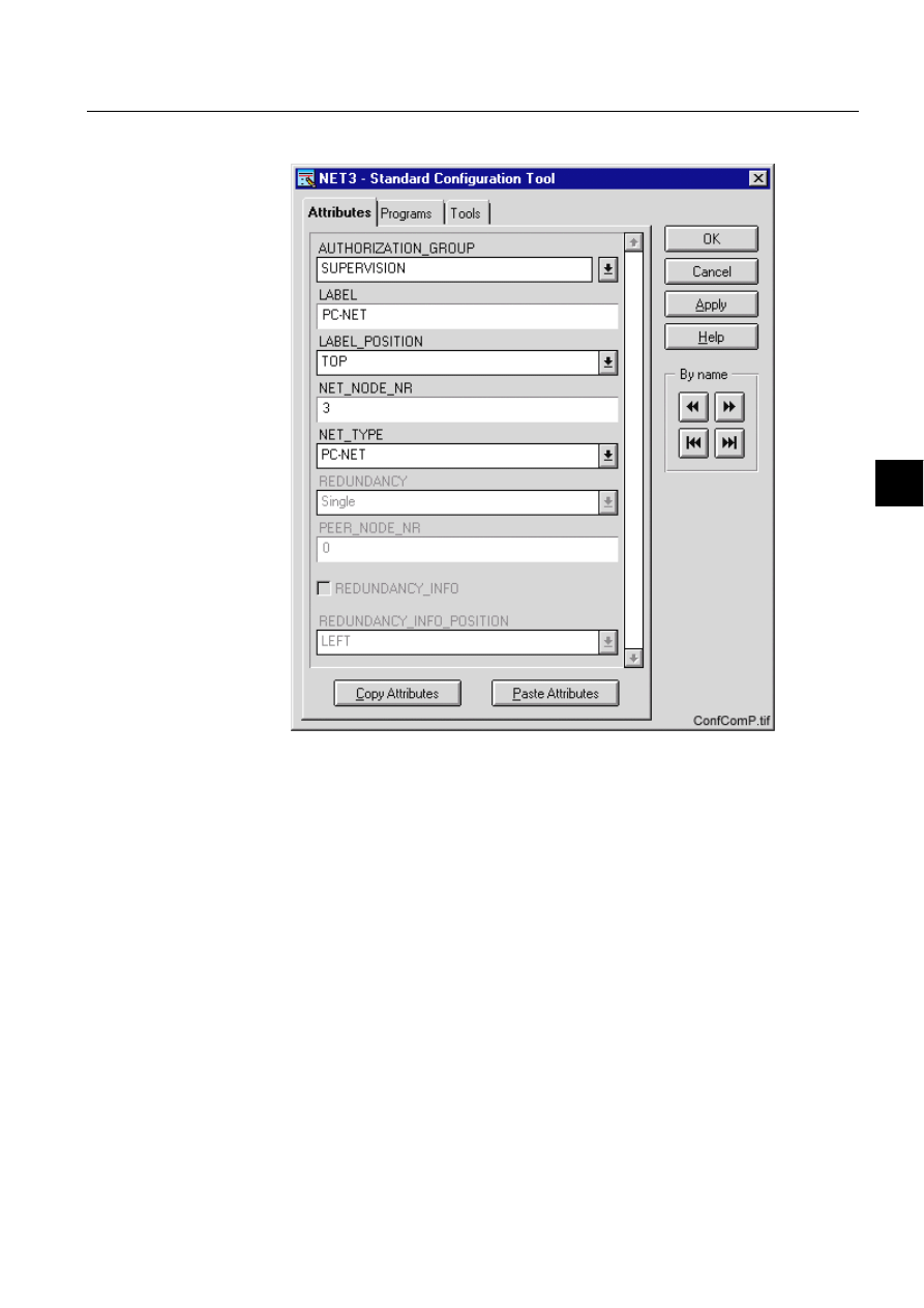
1MRS751880-MEN
LIB 500
211
LIB 500 Configuration Manual
Configuration Guide
8. System self supervision
8
8.9.4.5.
An example of communication unit configuration
)LJ $QH[DPSOHRIWKHFRQILJXUDWLRQRIWKHFRPPXQLFDWLRQXQLWSLFWXUH
IXQFWLRQ
8.9.4.6.
Information dialogs
As the communication unit object is being configured, the Information dialogs may
be displayed in case the system configuration does not exist or the system
configuration includes attribute value definitions that do not allow all the diagnostic
available for the System Self Supervision. More information can be found in the
Section 8.5.4.
8.9.5.
Application engineering information
8.9.5.1.
The structure of the communication unit picture function
This chapter describes the structure of the communication unit picture function. All
pictures, form pictures, help and other text files as well as all database objects are
included. The communication unit picture function is a part of the System Self
Supervision of LIB 500 and has a directory /LIB4/BASE/SYSTEM/, and the
standard LIB 500 sub-directories INST, LANG0 and USE.

212
1MRS751880-MEN
LIB 500 Configuration Manual
LIB 500
8. System self supervision Configuration Guide
The installation of the “instance” picture function will automatically install “type”
picture function (BSI_NETT) if it does not already exist. The “type” picture function
contains all common programs for the “instance” picture function and it is only
visible at the Picture Editor.
8.9.5.2.
Pictures
Below there is a list of all communication unit pictures and a short description of
their functionality. Dialogs are described in detail in the LIB 500 Operator’s
Manual, 1MRS751885-MUM (Chapter 6). The paths are
/LIB4/BASE/SYSTEM/INST/
Table 8.9.5.2-1
A list of the communication unit pictures and description of
their functionality (first path)
and /LIB4/BASE/SYSTEM/USE/
Table 8.9.5.2-2
A list of the communication unit pictures and description of
their functionality (second path)
8.9.5.3.
Help text files
Below there is a list of the communication unit help text files. The path is
/LIB4/BASE/SYSTEM/LANG0/.
Table 8.9.5.3-1
A list of the communication unit help text files
8.9.5.4.
Configuration files
The following configuration files are used by the communication unit picture
function. The path is
LIB4/BASE/SYSTEM/INST/
Picture
Functionality
BSI_NETT.PIC
Common programs for all NET picture functions
BSI_NETI_M.PIC
Medium picture function (3*2) for NET object
BSI_NETI_L.PIC
Large picture function (5*2) for NET object
Picture
Functionality
BSU_DLGA.PIC
Main dialog (common for all other picture functions, too).
BSU_DLGB.PIC
Device information dialog (common for all other picture
functions, too).
Help file
Functionality
BSI_NET2.HLP
Picture function installation help file
BSU_NET2.HLP
Main dialog help file

1MRS751880-MEN
LIB 500
213
LIB 500 Configuration Manual
Configuration Guide
8. System self supervision
8
Table 8.9.5.4-1
The configuration files used by the communication unit
picture function
8.9.5.5.
Other text files
The following text files are used by the communication unit. The path is
/LIB4/BASE/SYSTEM/USE/.
Table 8.9.5.5-1
The text files used by the communication unit
8.9.5.6.
System configuration
The operation of the communication unit object is based on the following events
• Events generated by the predefined event channel SYS_EVENT
• System messages (status codes) generated by the communication unit.
• Events generated by the command procedure SYS_NETSR
In order for the communication unit object to work properly, system events must be
enabled for the current application. Refer to the Section 8.3.1.1 for detailed
information.
The operation of the communication unit object is also based on the system
messages (status codes) generated by the communication unit. These status codes
are transferred to a MicroSCADA application database to addresses defined by the
attributes of the MicroSCADA system objects. In order for the communication unit
function to work properly, the attributes of the communication unit object
corresponding to the supervised communication unit must be set as the table below.
Table 8.9.5.6-1
The attributes of the communication unit object
corresponding to the supervised communication unit
Configuration file
Functionality
BSI_NET2.DAT
Contains the configuration data for NET object when it is
created, modified or deleted by configuration tools.
INDEX4_B11.TXT
Selection list of LIB 500 Rev 4.0.3 System Self Supervision
picture functions for installation tool (common for all other
picture functions, too).
Text file
Functionality
PATH4_B11.TXT
Contains the path definitions for the System Self Supervision
(common for all other picture functions, too).
Attribute
Value
SE (System Messages Enabled)
1 (messages enabled, default value)
MS (Message System)
Number of the application to receive the system
message as seen by the communication unit.
MI (Message Identification)
Same as the object address (OA) of the receiving
process object.
For each NET type, the MI default values are as follows:
6000 + NET object number

214
1MRS751880-MEN
LIB 500 Configuration Manual
LIB 500
8. System self supervision Configuration Guide
Also the other communication unit object attributes must be configured properly.
Since the communication unit does not send any message if it is terminated
abnormally, the state of the communication unit and each of it’s lines is read every
20 seconds (default) by the command procedure SYS_NETSR.
8.9.5.7.
Process objects
The database objects related to the communication unit object is created
automatically either in background as OK or Apply button is being clicked or by the
use of System Configuration Tool. More information can be found in the Section
8.3.4.7.
The following process objects will be created.
Table 8.9.5.7-1
Process Objects
8.9.5.8.
Scale objects
At first installation, the communication unit object creates the scale 1_1 (linear 1:1
scale) if the scale 1_1 does not exist.
8.9.5.9.
Command procedures
At first installation, the communication unit object creates the following command
procedures:
Table 8.9.5.9-1
Command Procedures
8.9.5.10.
Time channels
At first installation, the communication unit object creates the time channel
SYS_NETSR, if it does not exist.
Index
Obj. type
Process object
Remarks
Group identifier
10
AI
Communication unit state
-
BSWNETINET
11
AI
Communication unit
redundancy state
In case of
redundant
front-end pair
BSWNETINET
110
AI
System message
receiving, communication
unit state
-
BSWNETXNET
111
Ai
System message
receiving, communication
unit redundancy state
In case of
redundant
front-end pair
BSWNETXNET
Command
procedure
Functionality
Remarks
SYS_SYSER
Command procedure for receiving SYS_EVENT
events
-
SYS_NETMR
Command procedure for receiving the
communication unit system messages
-
SYS_NETSR
Command procedure for the communication unit
supervision
-

1MRS751880-MEN
LIB 500
215
LIB 500 Configuration Manual
Configuration Guide
8. System self supervision
8
8.9.5.11.
Event channels
At first installation, the communication unit object creates the following event
channels (if does not exist):
Table 8.9.5.11-1 Event Channels
8.10.
Communication unit line
8.10.1.
Target systems
MicroSCADA systems, especially system supervision pictures.
8.10.2.
Communication unit line support
• ANSI X3.28 Full Duplex or ACP line (for a redundant front-end pair)
• ASCII protocol for printer line
• RP570 Master line
• SPA line
• RP570 Slave line
• LON line
• IEC 870-5-101 Unbalanced Slave line
• IEC 870-5-101 Balanced Slave line
• IEC 870-5-101 Unbalanced Master line
• IEC 870-5-101 Balanced Master line
• IEC 870-5-103 Unbalanced Master line
• DNP 3.0 Slave line
• DNP 3.0 Master line
8.10.3.
Features/options
• Versatile configuration
• Device information
• Help in all dialogs
8.10.4.
Picture function installation
This chapter describes the installation of picture functions for the System Self
Supervision communication unit line (NET line) object. The picture function for the
NET line is found in the directory /LIB4/BASE/SYSTEM/INST/ and it should be
installed by using LIB4 installation procedures (LIB4 - LIB 500 - Supervision 2.x –
NET Line). This picture function is configured by using standard configuration tools
such as:
Event Channel
Functionality
Remarks
SYS_EVENT
Event channel for the predefined event of
SYS_EVENT
-
SYS_NETMR
Event channel for the communication unit system
messages
-
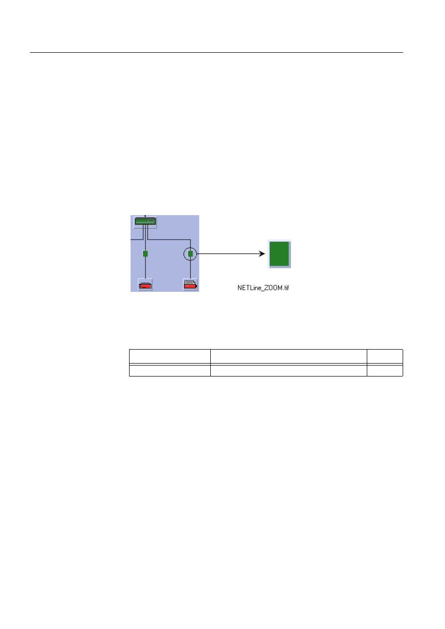
216
1MRS751880-MEN
LIB 500 Configuration Manual
LIB 500
8. System self supervision Configuration Guide
1. Standard Configuration Tool and
2. Representation Tool
8.10.4.1.
Environmental requirements
In order for the communication unit line to have full functionality, the following
component needs to be installed first:
• Base for 4.0.3
8.10.4.2.
Installation
The size of the communication unit line picture function is 16 x 20 pixels (1 x 1
semigraphical blocks). The button frame is drawn out of this area.
(see Fig. 8.10.4.2.-1) presents a communication unit line picture function as a part
of the system supervision picture.
)LJ ,QVWDOODWLRQIRUFRPPXQLFDWLRQXQLWOLQH1(7OLQHSLFWXUH
IXQFWLRQ
During the installation, the following information has to be given:
Table 8.10.4.2-1 Installation information
8.10.4.3.
Picture function configuration
Preliminary work
Before the configuration of the picture functions can start, some preparatory
configurations are required (i.e. configuration that are required only once). The
usage of the Object Identification (OI) -attribute has to be settled and the translation
of the signal texts into the local language has to be performed. Please refer to Section
8.3.2 for further information.
Please notify that the process objects of the communication unit line picture function
are created automatically in the background either as the Supervision Base
functionality is installed or as the picture function is configured. Thus, no
preliminary work for the process objects is required. However, it is necessary to
know how the system is configured (node number of the communication unit, line
number etc.).
Attribute
Meaning
Default
Picture function name
Name of the picture function within the picture
-

1MRS751880-MEN
LIB 500
217
LIB 500 Configuration Manual
Configuration Guide
8. System self supervision
8
Configuration with Standard Configuration Tool
The NET line picture function has the following attributes to configure with the
Standard Configuration Tool:
Table 8.10.4.3-1 The attributes of the NET line picture function to configure
with the Standard Configuration Tool
Attribute
Meaning
Default
AUTHORIZATION_GROUP
The name of the authorization group
SUPERVISION
LABEL
The abbreviation of the supervised
picture to be shown in the system
supervision picture.
-
LABEL_POSITION
Position of the label
TOP
NET_NODE_NR
The node number of the communication
unit (NET)
1
NET_LINE_NR
The line number of the communication
unit (NET)
1
WRITE_DEVICE_INFO
(in Programs folder)
An optional program by which three (3)
lines of device information are written to
the picture function. The maximum
length of each line is 28 characters.
Attribute
Meaning
AUTHORIZATION_GROUP
A selector type of an editable combo box to select the
authorization group for the object. The maximum length of
the text is 63 characters. The given text has to be usable as
a SCIL list attribute name (see the manual Programming
Language SCIL, 1MRS751849-MEN). The contents of the
selection list is taken from the existing authorization groups.
NOTE! The name may not be composed of two letters
followed by a number.
The attribute needs to be defined, if the object is wanted to
be included in some authorization group. The authorization
level of each user in this group can be defined afterwards by
the system manager with the User Management pictures.
LABEL
A text which will be placed outside the picture function
symbol as the picture is opened to the monitor. The position
of the text is determined by the LABEL_POSITION. The
maximum length of the LABEL is 15 characters.
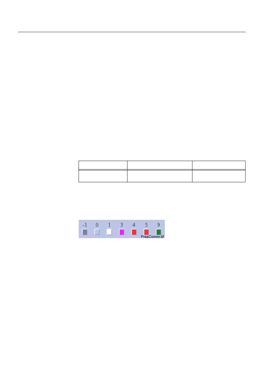
218
1MRS751880-MEN
LIB 500 Configuration Manual
LIB 500
8. System self supervision Configuration Guide
Configuration with Representation Tool
The communication unit line picture function has the following attributes to
configure with the Representation Tool (Refer to the Section 8.5.2 for further
details):
Table 8.10.4.3-2 The attributes of the communication unit line picture
function to configure with the Representation Tool
By default, there is one set of symbols in one size. This default presentation is shown
below. Please note that in actual system the symbol representing the selector 3 is
blinking to draw attention.
(see Fig. 8.10.4.3.-1) presents symbols for communication unit line.
)LJ 3UHVHQWDWLRQIRUWKHFRPPXQLFDWLRQXQLWOLQH
8.10.4.4.
Configuration with Process Object Tool
The communication unit line picture function has no attributes to configure with the
Process Object Tool.
LABEL_POSITION
A selector type of a combo box to select the position for the
LABEL text.
Valid values: "TOP", "BOTTOM", "LEFT" or "RIGHT"
NET_NODE_NR
The node number of the supervised communication unit
(NET).
Valid values: 1..20.
NOTE! By default the node number of the NET unit that will
be regarded as default NET unit (SYS:BDN) will be
displayed.
NET_LINE_NR
The line number of the supervised communication unit
(NET).
Valid values: 1..8.
Attribute
Meaning
Attribute
Meaning
Default
REPRESENTATION
Selection of symbol set shown in
picture
B_REPR/B_PCN8 or
B_REPR/B_PCNL8

1MRS751880-MEN
LIB 500
219
LIB 500 Configuration Manual
Configuration Guide
8. System self supervision
8
8.10.4.5.
An example of communication unit line configuration
)LJ $QH[DPSOHRIWKHFRQILJXUDWLRQRIWKHFRPPXQLFDWLRQXQLWOLQH
SLFWXUHIXQFWLRQ
8.10.4.6.
Information dialogs
As the communication unit line object is being configured, the Information dialogs
may be displayed in case the system configuration does not exist or the system
configuration includes attribute value definitions that do not allow all the diagnostic
available for the System Self Supervision. More information can be found in the
Section 8.5.4.
8.10.5.
Application engineering information
8.10.5.1.
The structure of the communication unit line picture function
This chapter describes the structure of the communication unit line picture function.
All pictures, form pictures, help and other text files as well as all database objects
are included. The communication unit line picture function is a part of the System
Self Supervision of LIB 500 and has a directory /LIB4/BASE/SYSTEM, and the
standard LIB 500 sub-directories INST, LANG0 and USE.

220
1MRS751880-MEN
LIB 500 Configuration Manual
LIB 500
8. System self supervision Configuration Guide
The installation of the “instance” picture function will automatically install “type”
picture function (BSI_NETLT) if it does not already exist. The “type” picture
function contains all common programs for the “instance” picture function and it is
only visible at the Picture Editor.
8.10.5.2.
Pictures
Below there is a list of all communication unit line pictures and a short description
of their functionality. Dialogs are described in detail in the LIB 500 Operator’s
Manual, 1MRS751885-MUM (Chapter 6). The paths are
/LIB4/BASE/SYSTEM/INST/
Table 8.10.5.2-1 A list of the communication unit line pictures and
description of their functionality (first path)
and /LIB4/BASE/SYSTEM/USE/
Table 8.10.5.2-2 A list of the communication unit line pictures and
description of their functionality (second path)
8.10.5.3.
Help text files
Below there is a list of the communication unit line help text files. The path is
/LIB4/BASE/SYSTEM/LANG0.
Table 8.10.5.3-1 A list of the communication unit line help text files
8.10.5.4.
Configuration files
The following configuration files are used by the communication unit line picture
function. The path is
LIB4/BASE/SYSTEM/INST/
Picture
Functionality
BSI_NETLT.PIC
Common programs for all NET line picture functions
BSI_NETLI.PIC
Picture function (1*1) for NET line object
Picture
Functionality
BSU_DLGA.PIC
Main dialog (common for all other picture functions, too).
BSU_DLGB.PIC
Device information dialog (common for all other picture
functions, too).
Help file
Functionality
BSI_NETL.HLP
Picture function installation help file
BSU_NETL.HLP
Main dialog help file

1MRS751880-MEN
LIB 500
221
LIB 500 Configuration Manual
Configuration Guide
8. System self supervision
8
Table 8.10.5.4-1 The configuration files used by the communication unit line
picture function
8.10.5.5.
Other text files
The following text files are used by the communication unit line. The path is
/LIB4/BASE/SYSTEM/USE/.
Table 8.10.5.5-1 The text files used by the communication unit line
8.10.5.6.
System configuration
The operation of the communication unit line object is based on the following events
• System messages (status codes) generated by the communication unit.
• Events generated by the command procedure SYS_NETSR
The operation of the communication unit line object is mainly based on the system
messages (status codes) generated by the communication unit. These status codes
are transferred to a MicroSCADA application database to addresses defined by the
attributes of the MicroSCADA system objects. In order for the communication unit
line function to work properly, the attributes of the communication unit line object
corresponding to the supervised communication unit line must be set as table below.
Table 8.10.5.6-1 The attributes of the communication unit line object
corresponding to the supervised communication unit line
Also the other communication unit line object attributes must be configured
properly. Since the communication unit (NET) does not send any message if it is
terminated abnormally, the state of the communication unit and each of it’s lines is
read every 20 seconds (default).
Configuration file
Functionality
BSI_NETL.DAT
Contains the configuration data for NET line object when it is
created, modified or deleted by configuration tools.
INDEX4_B11.TXT
Selection list of LIB 500 Rev 4.0.3 System Self Supervision
picture functions for installation tool (common for all other
picture functions, too).
Text file
Functionality
PATH4_B11.TXT
Contains the path definitions for the System Self Supervision
(common for all other picture functions, too).
Attribute
Value
SE (System Messages Enabled)
1 (messages enabled, default value)
MS (Message System)
Number of the application to receive the system
message as seen by the communication unit.
MI (Message Identification)
Same as the object address (OA) of the receiving
process object.
For each NET line, the MI default values are as follows:
6000 + (100+NET number)+NET line object number

222
1MRS751880-MEN
LIB 500 Configuration Manual
LIB 500
8. System self supervision Configuration Guide
8.10.5.7.
Process objects
The database objects related to the communication unit line object is created
automatically either in background as OK or Apply button is being clicked or by the
use of System Configuration Tool. More information can be found in the Section
8.3.4.7.
The following process objects will be created:
Table 8.10.5.7-1 Process Objects
8.10.5.8.
Scale objects
At first installation, the communication unit line object creates the scale 1_1 (linear
1:1 scale) if the scale 1_1 does not exist.
8.10.5.9.
Command procedures
At first installation, the communication unit object creates the command procedure
SYS_NETLMR, if it does not exist.
8.10.5.10.
Event channels
At first installation, the communication unit line object creates the event channel
SYS_NETLMR, if it does not exist.
8.11.
Station
8.11.1.
Target systems
MicroSCADA systems, especially system supervision pictures.
8.11.2.
Communication support
The following station types can be supervised with the station picture function:
• SPACOM / SPANET (SPA)
• RED 500 / REx (LON)
• RED 500 / LMK (LON)
• RTU 2xx (RP570 M)
• RTU 2xx (RP570 S)
• IEC (IEC 870-5-101/103)
• DNP 3.0 (DNP 3.0)
Index
Obj. type
Process object
Remarks
Group identifier
20
+
line number
AI
Communication unit line
state
-
BSWNETILIN
120
+
line number
AI
System message
receiving, communication
unit line state
-
BSWNETXLIN

1MRS751880-MEN
LIB 500
223
LIB 500 Configuration Manual
Configuration Guide
8. System self supervision
8
8.11.3.
Features/options
• Versatile configuration
• Device information
• Help in all dialogs
8.11.4.
Picture function installation
This chapter describes the installation of picture functions for the System Self
Supervision station object. The picture function for the station is found in the
directory /LIB4/BASE/SYSTEM/INST/ and it should be installed by using LIB4
installation procedures (LIB4 - LIB 500 - Supervision 2.x – Station). This picture
function is configured by using standard configuration tools such as:
1. Standard Configuration Tool and
2. Representation Tool
8.11.4.1.
Environmental requirements
In order for the station to have full functionality, the following component needs to
be installed first:
• Base for 4.0.3
8.11.4.2.
Installation
There are three different sizes of the station picture function: small (1*1), medium
(2*2) and large (3*2). The size of the small station picture function is 20 x 20 pixels
(1 x 1 semigraphical block), the medium station picture function is 32 x 40 pixels (2
x 2 semigraphical blocks) and the large picture function is 48 x 40 pixels (3 x 2
semigraphical blocks). The button frame is drawn out of this area.
(see Fig. 8.11.4.2.-1) presents different types of station picture functions in typical
installations.
S1.tif
Station, general
S2.tif
REx type of station, e.g. REF 543
224
1MRS751880-MEN
LIB 500 Configuration Manual
LIB 500
8. System self supervision Configuration Guide
)LJ ,QVWDOODWLRQIRUVWDWLRQSLFWXUHIXQFWLRQ
During the installation, the following information has to be given:
Table 8.11.4.2-1 Installation information
8.11.4.3.
Picture function configuration
Preliminary work
Before the configuration of the picture functions can start, some preparatory
configurations are required (i.e. configuration that are required only once). The
usage of the Object Identification (OI) -attribute has to be settled and the translation
of the signal texts into the local language has to be performed. Please refer to Section
8.3.2 for further information.
Please notify that the process objects of the station picture function are created
automatically in the background either as the Supervision Base functionality is
installed or as the picture function is configured. Thus, no preliminary work for the
process objects is required. However, it is necessary to know how the station is
configured (station number, node and line number of the communication unit etc.).
Configuration with Standard Configuration Tool
The station picture function has the following attributes to configure with the
Standard Configuration Tool.
S3.tif
SRIO type of station
S4.tif
RTU type of station
S5.tif
SACO type of station
Attribute
Meaning
Default
Picture function name
Name of the picture function within the picture
-

1MRS751880-MEN
LIB 500
225
LIB 500 Configuration Manual
Configuration Guide
8. System self supervision
8
Table 8.11.4.3-1 The attributes of the station picture function to configure
with the Standard Configuration Tool
Attribute
Meaning
Default
AUTHORIZATION_GROUP
The name of the authorization group
SUPERVISION
LABEL
The abbreviation of the supervised
picture to be shown in the system
supervision picture.
-
LABEL_POSITION
Position of the label
TOP
STATION_NR
The number of the supervised station
1
STATION_TYPE
The type of the supervised station.
RED 500 / REx
(LON)
NET_NODE_NR
The node number of the communication
unit (NET), where the station is
connected to
1
NET_LINE_NR
The line number of the communication
unit (NET) line, where the station is
connected to
1
WRITE_DEVICE_INFO
(in Programs folder)
An optional program by which three (3)
lines of device information are written to
the picture function. The maximum
length of each line is 28 characters.
-
AUTHORIZATION_GROUP
A selector type of an editable combo box to select the
authorization group for the object. The maximum length of
the text is 63 characters. The given text has to be usable as
a SCIL list attribute name (see the manual Programming
Language SCIL, 1MRS751849-MEN). The contents of the
selection list is taken from the existing authorization groups.
NOTE! The name may not be composed of two letters
followed by a number.
The attribute needs to be defined, if the object is wanted to
be included in some authorization group. The authorization
level of each user in this group can be defined afterwards by
the system manager with the User Management pictures.
LABEL
A text which will be placed outside the picture function
symbol as the picture is opened to the monitor. The position
of the text is determined by the LABEL_POSITION. The
maximum length of the LABEL is 15 characters.
LABEL_POSITION
A selector type of a combo box to select the position for the
LABEL text.
Valid values: "TOP", "BOTTOM", "LEFT" or "RIGHT"
STATION_NR
The number of the supervised station.
Valid values: 1..2000.
Default value: 1.

226
1MRS751880-MEN
LIB 500 Configuration Manual
LIB 500
8. System self supervision Configuration Guide
Configuration with Representation Tool
The station picture function has the following attributes to configure with the
Representation Tool (Refer to the Section 8.5.2 for further details).
Table 8.11.4.3-2 The attributes of the station picture function to configure
with the Representation Tool
By default, there is various numbers of sets of symbols in three different sizes.
Example of these default presentations is shown below. Please note that in actual
system the symbol representing the selector 3 is flashing to draw attention.
Table 8.11.4.3-3 Symbol presentations
STATION_TYPE
The type of the supervised station. Possible station types by
default are:
SPACOM / SPANET (SPA)
RED 500 / REx (LON)
RED 500 / LMK (LON)
RTU 2xx (RP570 M)
RTU 2xx (RP570 S)
IEC (IEC 870-5-101/103)
DNP 3.0 (DNP 3.0)
NOTE! By default the type of the supervised station is read
from the system configuration. If reading is successful (i.e.
system configuration for the specified station exists), the
configurable attribute is disabled.
NET_NODE_NR
The node number of the communication unit (NET), where
the station is connected to.
Valid values: 1..20.
NOTE! By default the node number of the NET unit, where
the station is connected to, is read from the system
configuration. If reading is successful (i.e. system
configuration for the specified station exists), the
configurable attribute is disabled.
NET_LINE_NR
The line number of the communication unit (NET) line,
where the station is connected to.
Valid values: 1..8.
NOTE! By default the line number of the NET unit, where the
station is connected to, is read from the system
configuration. If reading is successful (i.e. system
configuration for the specified station exists), the
configurable attribute is disabled.
Attribute
Meaning
Default
REPRESENTATION
Selection of symbol set shown in
picture
B_REPR/B_STA,
B_REPR/B_STAM1 or
B_REPR/B_STAL1
Symbol
Representation
Size
B_REPR/B_STA
General symbol for the station
Small
B_REPR/B_STAM1
General symbol for the station
Medium
B_REPR/B_STAM2
Symbol for REx type of station (e.g. REF 543)
Medium
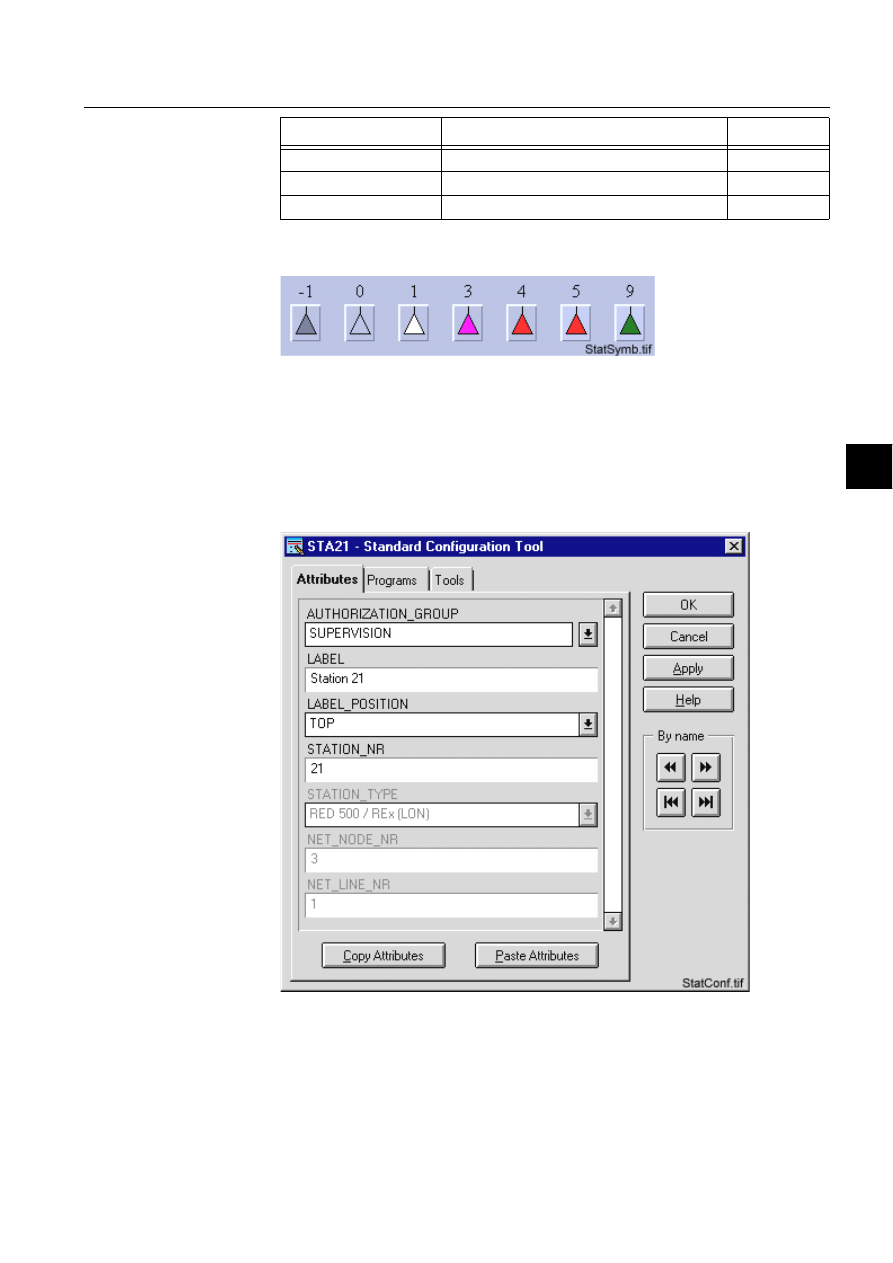
1MRS751880-MEN
LIB 500
227
LIB 500 Configuration Manual
Configuration Guide
8. System self supervision
8
Section 8.11.4.3.-1 presents general symbols for station.
)LJ *HQHUDOV\PEROIRUWKHVWDWLRQ
8.11.4.4.
Configuration with Process Object Tool
The station picture function has no attributes to configure with the Process Object
Tool.
8.11.4.5.
An example of station configuration
)LJ $QH[DPSOHRIWKHFRQILJXUDWLRQRIWKHVWDWLRQSLFWXUHIXQFWLRQ
B_REPR/B_STAL1
Symbol for SRIO type of station
Large
B_REPR/B_STAL2
Symbol for RTU type of station
Large
B_REPR/B_STAL3
Symbol for SACO type of station
Large
Symbol
Representation
Size

228
1MRS751880-MEN
LIB 500 Configuration Manual
LIB 500
8. System self supervision Configuration Guide
8.11.4.6.
Information dialogs
As the station object is being configured, the Information dialogs may be displayed
in case the system configuration does not exist or the system configuration includes
attribute value definitions that do not allow all the diagnostic available for the
System Self Supervision. More information can be found in the Section 8.5.4.
8.11.5.
Application engineering information
8.11.5.1.
The structure of the station picture function
This chapter describes the structure of the station picture function. All pictures, form
pictures, help and other text files as well as all database objects are included. The
station picture function is a part of the System Self Supervision of LIB 500 and has
a directory /LIB4/BASE/SYSTEM, and the standard LIB 500 sub-directories INST,
LANG0 and USE.
The installation of the “instance” picture function will automatically install “type”
picture function (BSI_STAT) if it does not already exist. The “type” picture function
contains all common programs for the “instance” picture function and it is only
visible at the Picture Editor.
8.11.5.2.
Pictures
Below there is a list of all station pictures and a short description of their
functionality. Dialogs are described in detail in the LIB 500 Operator’s Manual,
1MRS751885-MUM (Chapter 6). The paths are
/LIB4/BASE/SYSTEM/INST/
Table 8.11.5.2-1 A list of the station pictures and description of their
functionality (first path)
and /LIB4/BASE/SYSTEM/USE/
Table 8.11.5.2-2 A list of the station pictures and description of their
functionality (second path)
8.11.5.3.
Help text files
Below there is a list of the station help text files. The path is
/LIB4/BASE/SYSTEM/LANG0.
Picture
Functionality
BSI_STAT.PIC
Common programs for all station picture functions
BSI_STAI_S.PIC
Small picture function (1*1) for station object
BSI_STAI_M.PIC
Medium picture function (2*2) for station object
BSI_STAI_L.PIC
Large picture function (3*2) for station object
Picture
Functionality
BSU_DLGA.PIC
Main dialog (common for all other picture functions, too).
BSU_DLGB.PIC
Device information dialog (common for all other picture
functions, too).

1MRS751880-MEN
LIB 500
229
LIB 500 Configuration Manual
Configuration Guide
8. System self supervision
8
Table 8.11.5.3-1 A list of the station help text files
8.11.5.4.
Configuration files
The following configuration files are used by the station picture function. The path is
LIB4/BASE/SYSTEM/INST/
Table 8.11.5.4-1 The configuration files used by the station picture function
8.11.5.5.
Other text files
The following text files are used by the station. The path is
/LIB4/BASE/SYSTEM/USE/.
Table 8.11.5.5-1 The text files used by the station
8.11.5.6.
System configuration
The operation of the station object is based on the following events
• Events generated by the predefined event channel APL_EVENT
• System messages (status codes) generated by the communication unit.
In order for the station object to work properly, events in stations must be enabled
for the current application. Refer to the Section 8.3.1.1 for detailed information.
The operation of the station object is also based on the system messages (status
codes) generated by the communication unit. These status codes are transferred to a
MicroSCADA application database to addresses defined by the attributes of the
MicroSCADA system objects. In order for the station function to work properly, the
attributes of the station object corresponding to the supervised station must be set as
follows:
Help file
Functionality
BSI_STA2.HLP
Picture function installation help file
BSU_STA2.HLP
Main dialog help file
Configuration file
Functionality
BSI_STA2.DAT
Contains the configuration data for station object when it is
created, modified or deleted by configuration tools.
INDEX4_B11.TXT
Selection list of LIB 500 Rev 4.0.3 System Self Supervision
picture functions for installation tool (common for all other
picture functions, too).
Text file
Functionality
PATH4_B11.TXT
Contains the path definitions for the System Self Supervision
(common for all other picture functions, too).

230
1MRS751880-MEN
LIB 500 Configuration Manual
LIB 500
8. System self supervision Configuration Guide
Table 8.11.5.6-1 The attributes of the station object corresponding to the
supervised station
8.11.5.7.
Process objects
The database objects related to the station object are created automatically either in
background as OK or Apply button is being clicked or by the use of System
Configuration Tool. More information can be found in the Section 8.3.4.7.
The following process objects will be created:
Table 8.11.5.7-1 Process Objects
8.11.5.8.
Scale objects
At first installation, the station object creates the scale 1_1 (linear 1:1 scale) if the
scale 1_1 does not exist.
8.11.5.9.
Command Procedures
At first installation, the station object creates the following command procedures:
Attribute
Value
SE (System Messages Enabled)
1 (messages enabled, default value)
MS (Message System)
Number of the application to receive the system
message as seen by the communication unit.
MI (Message Identification)
Same as the object address (OA) of the receiving
process object.
For each station type, the MI default values are as
follows:
SPA, REX, LMK, SPI:
1000+station object number
IEC:
29000+station object number
DNP:
30000+station object number
RTU 2xx:
8000+station object number (NET int. messages) and
8500+station object number (RTU terminal status msg.)
Index
Obj. type
Process object
Remarks
Group identifier
10
AI
Station state
-
BSWSTAISTA
11
AI
RTU terminal status
In case of RTU
2xx type of
station
BSWSTAISTA
110
AI
System message
receiving, station state
-
BSWSTAXSTA
111
Ai
System message
receiving, RTU terminal
status
In case of RTU
2xx type of
station
BSWSTAXSTA

1MRS751880-MEN
LIB 500
231
LIB 500 Configuration Manual
Configuration Guide
8. System self supervision
8
Table 8.11.5.9-1 Command Procedures
8.11.5.10.
Event channels
At first installation, the station object creates the following event channels (if does
not exist):
Table 8.11.5.10-1Event Channels
8.12.
LON Clock Master (SLCM)
8.12.1.
Target systems
MicroSCADA systems, especially system supervision pictures.
8.12.2.
LON Clock Master support
• LON Clock Master (Master master mode)
• LON Clock Master (Redundant)
8.12.3.
Features/options
• Versatile configuration
• Device information
• Help in all dialogs
8.12.4.
Picture function installation
This chapter describes the installation of picture functions for the System Self
Supervision LON Clock Master (SLCM) object. The picture function for the SLCM
is found in the directory /LIB4/BASE/SYSTEM/INST/ and it should be installed by
using LIB4 installation procedures (LIB4 - LIB 500 - Supervision 2.x – LON Clock
Master (SLCM)). This picture function is configured by using standard
configuration tools such as:
1. Standard Configuration Tool and
2. Representation Tool
8.12.4.1.
Environmental requirements
In order for the LON Clock Master to have full functionality, the following
component needs to be installed first:
Command
procedure
Functionality
Remarks
SYS_APLER
Command procedure for receiving the APL_EVENT
events
-
SYS_STAMR
Command procedure for receiving the station
system messages
-
Event Channel
Functionality
Remarks
APL_EVENT
Event channel for the predefined event of
APL_EVENT
-
SYS_STAMR
Event channel for the station system messages
-
232
1MRS751880-MEN
LIB 500 Configuration Manual
LIB 500
8. System self supervision Configuration Guide
• Base for 4.0.3
8.12.4.2.
Installation
The size of the LON Clock Master picture function is 32 x 40 pixels (2 x 2
semigraphical blocks). The button frame is drawn out of this area.
(see Fig. 8.12.4.2.-1) presents a LON Clock Master picture function in a typical
installations.
)LJ ,QVWDOODWLRQIRU/21&ORFN0DVWHUSLFWXUHIXQFWLRQ
During the installation, the following information has to be given:
Table 8.12.4.2-1 Installation information
8.12.4.3.
Picture function configuration
Preliminary work
Before the configuration of the picture functions can start, some preparatory
configurations are required (i.e. configuration that are required only once). The
usage of the Object Identification (OI) attribute has to be settled and the translation
of the signal texts into the local language has to be performed. Please refer to Section
8.3.2 for further information.
Please notify that the process objects of the LON Clock Master picture function are
created automatically in the background either as the Supervision Base functionality
is installed or as the picture function is configured. Thus, no preliminary work for
the process objects is required. However, it is necessary to know how the station is
configured (SLCM number, node and line number of the communication unit etc.).
LO1.tif
LON Clock Master card
LO2.tif
Connection to GPS
LO3.tif
Clock status
Attribute
Meaning
Default
Picture function name
Name of the picture function within the picture
-

1MRS751880-MEN
LIB 500
233
LIB 500 Configuration Manual
Configuration Guide
8. System self supervision
8
Configuration with Standard Configuration Tool
The LON Clock Master picture function has the following attributes to configure
with the Standard Configuration Tool:
Table 8.12.4.3-1 The attributes of the LON Clock Master picture function to
configure with the Standard Configuration Tool.
Attribute
Meaning
Default
AUTHORIZATION_GROUP
The name of the authorization group
SUPERVISION
LABEL
The abbreviation of the supervised
picture to be shown in the system
supervision picture.
-
LABEL_POSITION
Position of the label
TOP
SLCM_NR
The number of the supervised LON
Clock Master
1
NET_NODE_NR
The node number of the communication
unit (NET), where the SLCM is
connected to
1
NET_LINE_NR
The line number of the communication
unit (NET) line, where the SLCM is
connected to
1
WRITE_DEVICE_INFO
(in Programs folder)
An optional program by which three
lines of device information are written to
the picture function. The maximum
length of each line is 28 characters.
-
AUTHORIZATION_GROUP
A selector type of an editable combo box to select the
authorization group for the object. The maximum length of
the text is 63 characters. The given text has to be usable as
a SCIL list attribute name (see the manual Programming
Language SCIL, 1MRS751849-MEN). The contents of the
selection list is taken from the existing authorization groups.
NOTE! The name may not be composed of two letters
followed by a number.
The attribute needs to be defined, if the object is wanted to
be included in some authorization group. The authorization
level of each user in this group can be defined afterwards by
the system manager with the User Management pictures.
LABEL
A text which will be placed outside the picture function
symbol as the picture is opened to the monitor. The position
of the text is determined by the LABEL_POSITION. The
maximum length of the LABEL is 15 characters.
LABEL_POSITION
A selector type of a combo box to select the position for the
LABEL text.
Valid values: "TOP", "BOTTOM", "LEFT" or "RIGHT"

234
1MRS751880-MEN
LIB 500 Configuration Manual
LIB 500
8. System self supervision Configuration Guide
Configuration with Representation Tool
The SLCM picture function has the following attributes to configure with the
Representation Tool (Refer to the Section 8.5.2 for further details):
Table 8.12.4.3-2 The attributes of the SLCM picture function to configure with
the Representation Tool.
By default, there are three sets of symbols in one size. Example of these default
presentations is shown below. Please note that in actual system the symbol
representing the selector 3 is flashing to draw attention.
Table 8.12.4.3-3 Symbol presentations
(see Fig. 8.12.4.3.-1) presents LON Clock Master card symbols for the SLCM.
)LJ /21&ORFN0DVWHUFDUGV\PEROIRUWKH6/&0
SLCM_NR
The number of the supervised SLCM.
Valid values: 1..2000.
Default value: 1.
NET_NODE_NR
The node number of the communication unit (NET), where
the SLCM is connected to.
Valid values: 1..20.
NOTE! By default the node number of the NET unit, where
the station is connected to, is read from the system
configuration. If reading is successful (i.e. system
configuration for the specified station exists), the
configurable attribute is disabled.
NET_LINE_NR
The line number of the communication unit (NET) line,
where the SLCM is connected to.
Valid values: 1..8.
NOTE! By default the line number of the NET unit, where the
SLCM is connected to, is read from the system
configuration. If reading is successful (i.e. system
configuration for the specified station exists), the
configurable attribute is disabled.
Attribute
Meaning
Default
REPRESENTATION
Selection of symbol set shown in
picture
B_REPR/B_SLCM1
Symbol
Representation
Size
B_REPR/B_SLCM1
Symbol of LON Clock Master (SLCM) card
Medium
B_REPR/B_SLCM2
Symbol of GPS connection
Medium
B_REPR/B_SLCM3
Symbol of clock status
Medium
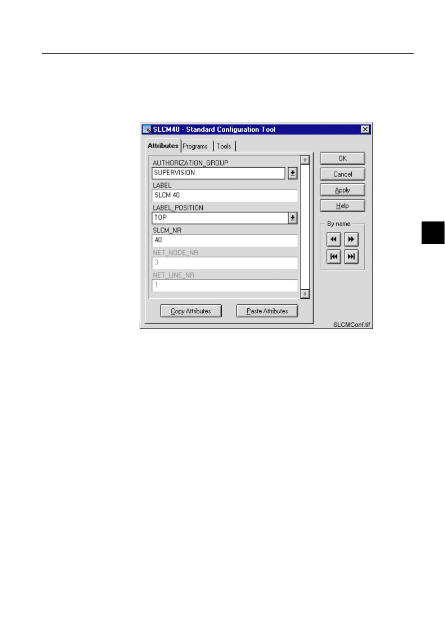
1MRS751880-MEN
LIB 500
235
LIB 500 Configuration Manual
Configuration Guide
8. System self supervision
8
8.12.4.4.
Configuration with Process Object Tool
The SLCM picture function has no attributes to configure with the Process Object
Tool.
8.12.4.5.
An example of LON Clock Master configuration
)LJ $QH[DPSOHRIWKHFRQILJXUDWLRQRIWKH6/&0SLFWXUHIXQFWLRQ
8.12.4.6.
Information dialogs
As the SLCM object is being configured, the Information dialogs may be displayed
in case the system configuration does not exist or the system configuration includes
attribute value definitions that do not allow all the diagnostic available for the
System Self Supervision. More information can be found in the Section 8.5.4.
8.12.5.
Application engineering information
8.12.5.1.
The structure of the LON Clock Master picture function
This chapter describes the structure of the SLCM picture function. All pictures, form
pictures, help and other text files as well as all database objects are included. The
SLCM picture function is a part of the System Self Supervision of LIB 500 and has
a directory /LIB4/BASE/SYSTEM, and the standard LIB 500 sub-directories INST,
LANG0 and USE.
The installation of the “instance” picture function will automatically install “type”
picture function (BSI_SLCMT) if it does not already exist. The “type” picture
function contains all common programs for the “instance” picture function and it is
only visible at the Picture Editor.

236
1MRS751880-MEN
LIB 500 Configuration Manual
LIB 500
8. System self supervision Configuration Guide
8.12.5.2.
Pictures
Below there is a list of all SLCM pictures and a short description of their
functionality. Dialogs are described in detail in the LIB 500 Operator’s Manual,
1MRS751885-MUM (Chapter 6). The paths are
/LIB4/BASE/SYSTEM/INST/
Table 8.12.5.2-1 A list of the SLCM pictures and description of their
functionality (first path)
and /LIB4/BASE/SYSTEM/USE/
Table 8.12.5.2-2 A list of the SLCM pictures and description of their
functionality (second path)
8.12.5.3.
Help text files
Below there is a list of the SLCM help text files. The path is
/LIB4/BASE/SYSTEM/LANG0.
Table 8.12.5.3-1 A list of the SLCM help text files
8.12.5.4.
Configuration files
The following configuration files are used by the SLCM picture function. The path
is
LIB4/BASE/SYSTEM/INST/
Table 8.12.5.4-1 The configuration files used by the SLCM picture function
Picture
Functionality
BSI_SLCMT.PIC
Common programs for all SLCM picture functions
BSI_SLCMI.PIC
Picture function (3*2) for SLCM object
Picture
Functionality
BSU_DLGA.PIC
Main dialog (common for all other picture functions, too).
BSU_DLGB.PIC
Device information dialog (common for all other picture
functions, too).
BSU_DLGC.PIC
LON Clock Master diagnostic dialog
Help file
Functionality
BSI_SLCM.HLP
Picture function installation help file
BSU_SLCM.HLP
Main dialog help file
BSU_SLCM2.HLP
LON Clock Master diagnostic dialog help file
Configuration file
Functionality
BSI_SLCM.DAT
Contains the configuration data for SLCM object when it is
created, modified or deleted by configuration tools.
INDEX4_B11.TXT
Selection list of LIB 500 Rev 4.0.3 System Self Supervision
picture functions for installation tool (common for all other
picture functions, too).

1MRS751880-MEN
LIB 500
237
LIB 500 Configuration Manual
Configuration Guide
8. System self supervision
8
8.12.5.5.
Other text files
The following text files are used by the SLCM. The path is
/LIB4/BASE/SYSTEM/USE/.
Table 8.12.5.5-1 The text files used by the SLCM
8.12.5.6.
System configuration
The operation of the LON Clock Master object is based on the following events
• Events generated by the predefined event channel APL_EVENT (station
communication)
• System messages (status codes) generated by the communication unit (station
communication)
• Network variables of the SLCM card. Refer to the Section 8.3.3.2
In order to get all the diagnostic data concerning the NETs and the LMK stations of
communication system, the Diagnostic Interval (DI) -attributes for both of these
objects has to be set higher than value 0. In addition, if there is a printer line in
question, the Output Synchronization (OS) -attribute of this line has to be equal to
3, or in case of LON line used with a LON Clock Master (SLCM), the Link Type
(LK) –attribute of this line has to be equal to 0.
For the NETs this attribute determines the time in seconds between diagnostic
messages from the MicroSCADA base system to the NET. A failed diagnostic
message generates an event node connection lost and successful diagnostic message
generates an event node connection found. These both events are generated through
predefined event SYS_EVENT. As default, value of this attribute for NET
communication system object is set to 0. This value represents that no diagnostic
messages are being sent.
In case of the LMK station this attribute determines the time in seconds between the
periodical polls of the node status of the physical device. The status poll is used for
checking that the connection is alive. A failed status poll suspends the station. As
default, value of this attribute for station communication system object is set to 0.
This value represents that no connection check polling is being used.
In case of the NET line for printer, the Output Synchronization (OS) -attribute has
to be set to 3 (XON/XOFF with DCD supervision) in order to get all the diagnostic
data concerning the printer connected to a communication unit. The Output
Synchronization attribute applies to printer lines only and it defines the flow control
principle used by the printer. Please note that the cable wiring of the printer
connection differs depending on the value of Output Synchronization attribute, see
the Installation Manual for further details.
If the LON Clock Master (SLCM) is used in the NET line for LON communication
in order to synchronize other devices according to time information received from
the clock reference device (e.g. GPS), the Link Type attribute has to be set to 0 (no
Text file
Functionality
PATH4_B11.TXT
Contains the path definitions for the System Self Supervision
(common for all other picture functions, too).

238
1MRS751880-MEN
LIB 500 Configuration Manual
LIB 500
8. System self supervision Configuration Guide
clock synchronization). As default, value of this attribute is set to 3 (send LSG and
minute pulse).
• Section 8.3.3.3 for further details
In order for the SLCM object to work properly, events in stations must be enabled
for the current application. Refer to the Section 8.3.1.1 for detailed information.
The operation of the SLCM object is also based on the system messages (status
codes) generated by the communication unit. These status codes are transferred to a
MicroSCADA application database to addresses defined by the attributes of the
MicroSCADA system objects. In order for the station function to work properly, the
attributes of the station object corresponding to the supervised station must be set as
the table below.
Table 8.12.5.6-1 The attributes of the station object corresponding to the
supervised station
8.12.5.7.
Process objects
The database objects related to the SLCM object is created automatically either in
background as OK or Apply button is being clicked or by the use of System
Configuration Tool. More information can be found in the Section 8.3.4.7.
The following process objects will be created:
Table 8.12.5.7-1 Process Objects
Attribute
Value
SE (System Messages Enabled)
1 (messages enabled, default value)
MS (Message System)
Number of the application to receive the system
message as seen by the communication unit.
MI (Message Identification)
Same as the object address (OA) of the receiving
process object.
For each SLCM type, the MI default values are as
follows:
Station communication:
1000+SLCM object number
Clock status diagnostics:
Active SLCM: 255 * SLCM object number
Redundant SLCM: 255 * SLCM object number + 127
Index
Obj. type
Process object
Remarks
Group identifier
10
AI
Station state
-
BSWSTAISTA
11
AI
Active SLCM state
-
BSWSTAILCM
12
AI
Redundant SLCM state
-
BSWSTAILCM
110
AI
System message
receiving, station state
-
BSWSTAXSTA
111
AI
System message
receiving, active SLCM
state
-
BSWSTAXLCM
112
AI
System message
receiving, redundant
SLCM state
-
BSWSTAXLCM

1MRS751880-MEN
LIB 500
239
LIB 500 Configuration Manual
Configuration Guide
8. System self supervision
8
8.12.5.8.
Scale objects
At first installation, the LON Clock Master object creates the scale 1_1 (linear 1:1
scale) if the scale 1_1 does not exist.
8.12.5.9.
Command procedures
At first installation, the LON Clock Master object creates the following command
procedures:
Table 8.12.5.9-1 Command Procedures
8.12.5.10.
Event channels
At the first installation, the LON Clock Master object creates the following event
channels (if does not exist):
Table 8.12.5.10-1Event Channels
8.13.
Printer
8.13.1.
Target systems
MicroSCADA systems, especially system supervision pictures.
8.13.2.
Printer support
• Printers that are connected to a communication unit (NET) using ASCII protocol
• Other printers (as static)
8.13.3.
Features/options
• Versatile configuration
• Device information
• Help in all dialogs
Command
procedure
Functionality
Remarks
SYS_APLER
Command procedure for receiving the APL_EVENT
events
-
SYS_STAMR
Command procedure for receiving the station
system messages
-
SYS_SLCMR
Command procedure for receiving clock status
information from the LON Clock Master (SLCM)
-
Event Channel
Functionality
Remarks
APL_EVENT
Event channel for the predefined event of
APL_EVENT
-
SYS_STAMR
Event channel for the station system messages
-
SYS_SLCMR
Event channel for the LON Clock Master (SLCM)
clock status messages
-
240
1MRS751880-MEN
LIB 500 Configuration Manual
LIB 500
8. System self supervision Configuration Guide
8.13.4.
Picture function installation
This chapter describes the installation of picture functions for the System Self
Supervision printer object. The picture function for the printer is found in the
directory /LIB4/BASE/SYSTEM/INST/ and it should be installed by using LIB4
installation procedures (LIB4 - LIB 500 - Supervision 2.x – Printer). This picture
function is configured by using standard configuration tools such as:
1. Standard Configuration Tool and
2. Representation Tool
8.13.4.1.
Environmental requirements
In order for the printer to have full functionality, the following component needs to
be installed first:
• Base for 4.0.3
8.13.4.2.
Installation
The size of the printer picture function is 48 x 40 pixels (3 x 2 semigraphical blocks).
The button frame is drawn out of this area.
(see Fig. 8.13.4.2.-1) presents a printer picture function in a typical installation.
)LJ ,QVWDOODWLRQIRUSULQWHUSLFWXUHIXQFWLRQ
P1.tif
Matrix event printer
P2.tif
Color matrix event printer
P3.tif
Color laser printer i.e. hardcopy printer
P4.tif
Matrix event printer
P5.tif
Matrix event printer, old presentation

1MRS751880-MEN
LIB 500
241
LIB 500 Configuration Manual
Configuration Guide
8. System self supervision
8
During the installation, the following information has to be given:
Table 8.13.4.2-1 Installation information
8.13.4.3.
Picture function configuration
Preliminary work
Before the configuration of the picture functions can start, some preparatory
configurations are required (i.e. configuration that are required only once). The
usage of the Object Identification (OI) -attribute has to be settled and the translation
of the signal texts into the local language has to be performed. Please refer to Section
8.3.2 for further information.
Please notify that the process objects of the printer picture function are created
automatically in the background either as the Supervision Base functionality is
installed or as the picture function is configured. Thus, no preliminary work for the
process objects is required. However, it is necessary to know how the system is
configured (printer number etc.).
Configuration with Standard Configuration Tool
The printer picture function has the following attributes to configure with the
Standard Configuration Tool.
Table 8.13.4.3-1 The attributes of the printer picture function to configure
with the Standard Configuration Tool.
Attribute
Meaning
Default
Picture function name
Name of the picture function within the picture
-
Attribute
Meaning
Default
AUTHORIZATION_
GROUP
The name of the authorization group
SUPERVISION
LABEL
The abbreviation of the supervised
picture to be shown in the system
supervision picture.
-
LABEL_POSITION
Position of the label
TOP
PRINTER_NR
Number of the printer
1
PRINTER_CONN_TYPE
The type of the printer connection for
the supervised printer.
1
NET_NODE_NR
The node number of the communication
unit (NET), where the printer is
connected to.
1
NET_LINE_NR
The line number of the communication
unit (NET) line, where the printer is
connected to.
1
WRITE_DEVICE_INFO
(in Programs folder)
An optional program by which three
lines of device information are written to
the picture function. The maximum
length of each line is 28 characters.
-

242
1MRS751880-MEN
LIB 500 Configuration Manual
LIB 500
8. System self supervision Configuration Guide
AUTHORIZATION_
GROUP
A selector type of an editable combo box to select the
authorization group for the object. The maximum length of
the text is 63 characters. The given text has to be usable as
a SCIL list attribute name (see the manual Programming
Language SCIL, 1MRS751849-MEN). The contents of the
selection list is taken from the existing authorization groups.
NOTE! The name may not be composed of two letters
followed by a number.
The attribute needs to be defined, if the object is wanted to
be included in some authorization group. The authorization
level of each user in this group can be defined afterwards by
the system manager with the User Management pictures.
LABEL
A text which will be placed outside the picture function
symbol as the picture is opened to the monitor. The position
of the text is determined by the LABEL_POSITION. The
maximum length of the LABEL is 15 characters.
LABEL_POSITION
A selector type of a combo box to select the position for the
LABEL text.
Valid values: "TOP", "BOTTOM", "LEFT" or "RIGHT"
PRINTER_NR
The number of the supervised printer.
Valid values: 1..20.
Default value: 1

1MRS751880-MEN
LIB 500
243
LIB 500 Configuration Manual
Configuration Guide
8. System self supervision
8
Configuration with Representation Tool
The printer picture function has the following attributes to configure with the
Representation Tool (Refer to the Section 8.5.2 for further details):
Table 8.13.4.3-2 The attributes of the printer picture function to configure
with the Representation Tool.
By default, there are five sets of symbols in one size. Example of these default
presentations is shown below. Please note that in actual system the symbol
representing the selector 3 is flashing to draw attention.
PRINTER_CONN_TYPE
The type of the printer connection for the supervised printer.
Valid values: "NONE", "LINE", "NET" or "CONSOLE"
NOTE! By default the printer connection type of the printer
object is read from the system configuration,
(PRI<pri.number>:BDT). If reading is successful (i.e. system
configuration for the specified printer exists), the
configurable attribute is disabled.
If the type of the printer connection for the supervised printer
is "NET" (i.e. printer is connected to a NET unit), the
following attributes are enabled:
- NET_NODE_NR
- NET_LINE_NR
NET_NODE_NR
The node number of the communication unit (NET), where
the printer is connected to.
Valid values: 1..20.
This configurable attribute is significant only if the printer is
connected to a NET unit.
NOTE! By default the node number of the NET unit, where
the printer is connected to, is read from the system
configuration.
If reading is successful (i.e. system configuration for the
specified printer exists), the configurable attribute is
disabled.
NET_LINE_NR
The line number of the communication unit (NET) line,
where the printer is connected to.
Valid values: 1..8.
This configurable attribute is significant only if the printer is
connected to a NET unit.
NOTE! By default the line number of the NET unit, where the
printer is connected to, is read from the system
configuration.
If reading is successful (i.e. system configuration for the
specified printer exists), the configurable attribute is
disabled.
Attribute
Meaning
Default
REPRESENTATION
Selection of symbol set shown in
picture
B_REPR/B_SLCM1
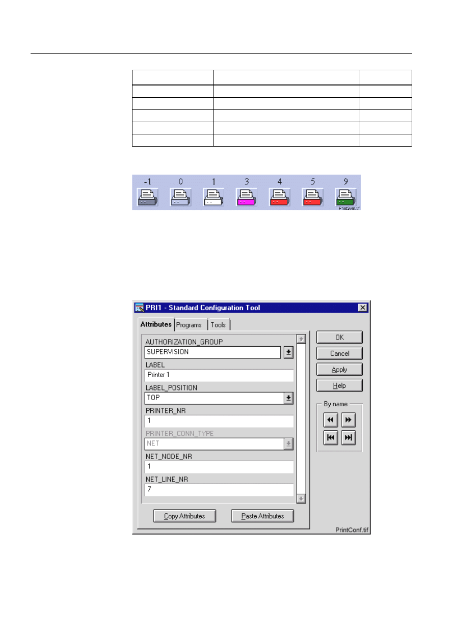
244
1MRS751880-MEN
LIB 500 Configuration Manual
LIB 500
8. System self supervision Configuration Guide
Table 8.13.4.3-3 Symbol presentation
(see Fig. 8.13.4.3.-1) presents matrix event printer symbol for the printer.
)LJ 0DWUL[HYHQWSULQWHUIRUWKHSULQWHU
8.13.4.4.
Configuration with Process Object Tool
The printer picture function has no attributes to configure with the Process Object
Tool.
8.13.4.5.
An example of printer configuration
)LJ $QH[DPSOHRIWKHFRQILJXUDWLRQRIWKHSULQWHUSLFWXUHIXQFWLRQ
Symbol
Representation
Size
B_REPR/B_PRINT1
Symbol of matrix event printer
Medium
B_REPR/B_PRINT2
Symbol of color matrix event printer
Medium
B_REPR/B_PRINT3
Symbol of color laser event printer
Medium
B_REPR/B_PRINT4
Symbol of matrix printer
Medium
B_REPR/B_PRINT5
Symbol of matrix printer (old presentation)
Medium

1MRS751880-MEN
LIB 500
245
LIB 500 Configuration Manual
Configuration Guide
8. System self supervision
8
8.13.4.6.
Information dialogs
As the printer object is being configured, the Information dialogs may be displayed
in case the system configuration does not exist or the system configuration includes
attribute value definitions that do not allow all the diagnostic available for the
System Self Supervision. More information can be found in the Section 8.5.4.
8.13.5.
Application engineering information
8.13.5.1.
The structure of the printer picture function
This chapter describes the structure of the printer picture function. All pictures, form
pictures, help and other text files as well as all database objects are included. The
printer picture function is a part of the System Self Supervision of LIB 500 and has
a directory /LIB4/BASE/SYSTEM, and the standard LIB 500 sub-directories INST,
LANG0 and USE.
The installation of the “instance” picture function will automatically install “type”
picture function (BSI_PRINTT) if it does not already exist. The “type” picture
function contains all common programs for the “instance” picture function and it is
only visible at the Picture Editor.
8.13.5.2.
Pictures
Below there is a list of all printer pictures and a short description of their
functionality. Dialogs are described in detail in the LIB 500 Operator’s Manual,
1MRS751885-MUM (Chapter 6). The paths are
/LIB4/BASE/SYSTEM/INST/
Table 8.13.5.2-1 A list of the printer pictures and description of their
functionality (first path)
and /LIB4/BASE/SYSTEM/USE/
Table 8.13.5.2-2 A list of the printer pictures and description of their
functionality (second path)
8.13.5.3.
Help text files
Below there is a list of the printer help text files. The path is
/LIB4/BASE/SYSTEM/LANG0/.
Picture
Functionality
BSI_PRINTT.PIC
Common programs for all printer picture functions
BSI_PRINTI.PIC
Picture function (3*2) for printer object
Picture
Functionality
BSU_DLGA.PIC
Main dialog (common for all other picture functions, too).
BSU_DLGB.PIC
Device information dialog (common for all other picture
functions, too).

246
1MRS751880-MEN
LIB 500 Configuration Manual
LIB 500
8. System self supervision Configuration Guide
Table 8.13.5.3-1 A list of the printer help text files
8.13.5.4.
Configuration files
The following configuration files are used by the printer picture function. The path is
LIB4/BASE/SYSTEM/INST/
Table 8.13.5.4-1 The configuration files used by the printer picture function
8.13.5.5.
Other text files
The following text files are used by the printer. The path is
/LIB4/BASE/SYSTEM/USE/.
Table 8.13.5.5-1 The text files used by the printer
8.13.5.6.
System configuration
The operation of the printer object is based on the following events
• Events generated by the predefined event channel SYS_EVENT
• System messages (status codes) generated by the communication unit.
In order for the printer object to work properly, system events must be enabled for
the current application. Refer to the Section 8.3.1.1 for detailed information.
The operation of the printer object is also based on the system messages (status
codes) generated by the communication unit. These status codes are transferred to a
MicroSCADA application database to addresses defined by the attributes of the
MicroSCADA system objects. In order for the printer object to work properly, the
attributes of the printer object corresponding to the supervised printer must be set as
the table below.
Help file
Functionality
BSI_PRINT2.HLP
Picture function installation help file
BSU_PRINT2.HLP
Main dialog help file
Configuration file
Functionality
BSI_PRINT2.DAT
Contains the configuration data for printer object when it is
created, modified or deleted by configuration tools.
INDEX4_B11.TXT
Selection list of LIB 500 Rev 4.0.3 System Self Supervision
picture functions for installation tool (common for all other
picture functions, too).
Text file
Functionality
PATH4_B11.TXT
Contains the path definitions for the System Self Supervision
(common for all other picture functions, too).

1MRS751880-MEN
LIB 500
247
LIB 500 Configuration Manual
Configuration Guide
8. System self supervision
8
Table 8.13.5.6-1 The attributes of the printer object corresponding to the
supervised printer
8.13.5.7.
Process objects
The database objects related to the printer object is created automatically either in
background as OK or Apply button is being clicked or by the use of System
Configuration Tool. More information can be found in the Section 8.3.4.7.
The following process objects will be created:
Table 8.13.5.7-1 Process Objects
8.13.5.8.
Scale objects
At first installation, the printer object creates the scale 1_1 (linear 1:1 scale) if the
scale 1_1 does not exist.
8.13.5.9.
Command procedures
At first installation, the printer object creates the following command procedures:
Table 8.13.5.9-1 Command Procedures
8.13.5.10.
Event channels
At first installation, the printer object creates the following event channels (if does
not exist):
Attribute
Value
SE (System Messages Enabled)
1 (messages enabled, default value)
MS (Message System)
Number of the application to receive the system
message as seen by the communication unit.
MI (Message Identification)
Same as the object address (OA) of the receiving
process object.
For each printer type, the MI default values are as
follows: 3000+printer object number
Index
Obj. type
Process object
Remarks
Group identifier
10
AI
Printer state
-
BSWPRIIPRI
110
AI
System message
receiving, printer state
-
BSWPRIXPRI
Command
procedure
Functionality
Remarks
SYS_SYSER
Command procedure for receiving the SYS_EVENT
events
-
SYS_PRIMR
Command procedure for receiving the printer
system messages
-

248
1MRS751880-MEN
LIB 500 Configuration Manual
LIB 500
8. System self supervision Configuration Guide
Table 8.13.5.10-1Event Channels
8.14.
SACO watch dog function
In substations there is a need to get a quick survey of any malfunction in the process.
An alarm function presented on a lamp panel with an audible horn informs the
personal on the station about an abnormal situation. The SCS monitor presents
additional information about the process state.
This is a description about how to use the SACO 16D_ annunciator together with the
SWD program for presentation of process group alarms, alarms from the internal
supervision and from SPACOM device supervision of the MicroSCADA/SCS
system.
The SWD program supervises the alarm situation in the SCS process database and
the function of the MicroSCADA/SCS system itself. Any internal malfunction in the
SCS system is presented in the same way as a process alarm on the SACO
annunciator. The SWD activates an alarm input on the SACO if anything is
abnormal in the SCS system. The SWD program uses the serial port in the main
computer for communication with the SACO annunciator. The ISA A-1 alarm
sequence is used for the alarm presentation. The computer can not affect the SWD
function when using a stand-alone annunciator and there is no need of extra slots in
the main computer.
8.14.1.
Hardware requirements
The following hardware is required for the SWD function:
• SACO 16D_ B unit
• Communication equipment:
• permanent connection: SPA - ZC4 and SPA - ZP 13A_
• temporary connection: SPA - ZP6A_ and SPA - ZP21A
• The MicroSCADA base system computer with a free COM port
8.14.2.
Functional description
8.14.2.1.
Alarms generated by the process through the SCS system
There are seven equally significant alarm classes for grouping alarms in the system.
The application engineer chooses how to group the objects in alarm classes e.g.
based on object’s location or alarm type. An object with alarm class 0 has no alarm
function. All objects belonging to the same class have the same type of audio-visual
alarms. The alarm indicator starts flashing when an alarm input is activated by the
SWD program. The alarm light stays on with a steady light after an
acknowledgement until the SWD program deactivates the input. At the same time
the SACO activates the horn and it is shut off with the silence push-button in the
front of the annunciator. When the system operator has acknowledged all alarms in
the SCS alarm list, the SWD program sends an acknowledge signal to the SACO.
Event Channel
Functionality
Remarks
SYS_EVENT
Event channel for the predefined event of
SYS_EVENT
-
SYS_PRIMR
Event channel for the printer system messages
-
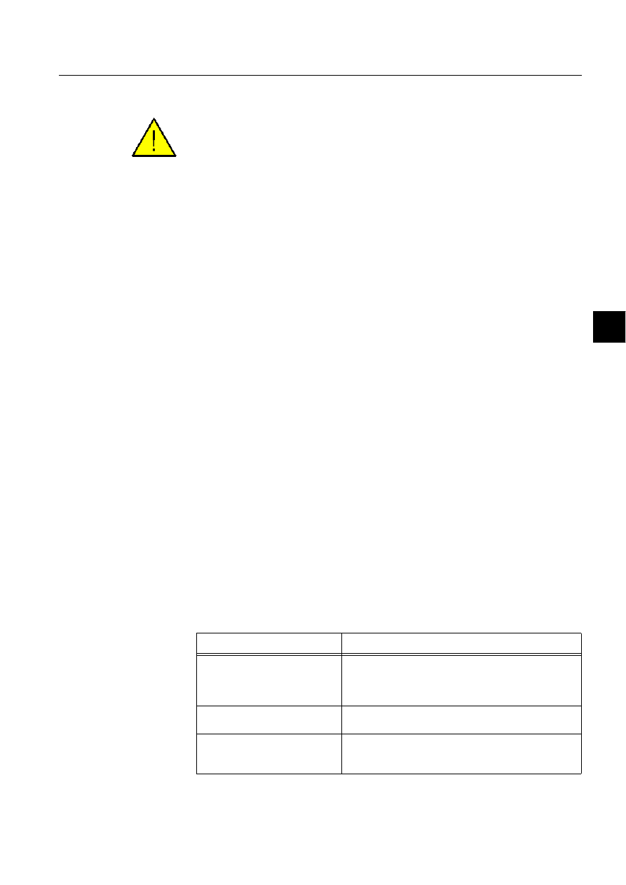
1MRS751880-MEN
LIB 500
249
LIB 500 Configuration Manual
Configuration Guide
8. System self supervision
8
8.14.2.2.
External alarms
The external alarms are not brought into the SCS system.
There are four alarm channels reserved to make redundant alarm functions for the
system. The channels can be direct wired to field contacts in the process. The alarm
presentation is similar to the process alarms activated via the SCS system.
8.14.2.3.
System alarm for the internal supervision
The internal supervision of the control system itself is almost as important as the
process alarms. Therefore, three system alarms are reserved for the internal
supervision; internal system fault for the MicroSCADA base system, front-end and
SPACOM module supervision.
8.14.2.4.
The watch dog function
The Watchdog function in the SWD program supervises the MicroSCADA base
system by sending a message to a pulse output relay in the SACO annunciator at
regular intervals. If the message does not come within the programmed interval, the
relay contact opens and this in turn activates the alarm channel 9.
8.14.2.5.
Front-end supervision
The SWD program supervises the front-end by asking for some data from the front-
end registers. If the SWD program does not get contact with the front-end then it
activates the alarm channel 10.
8.14.2.6.
SPACOM communication supervision
The front-end computer supervises the SPACOM modules continuously. The
information about missing SPACOM modules is sent through the MicroSCADA
base system to the alarm channel 11. The alarm activation for SPACOM devices are
based on system messages from the front-ends. The front-end is sending a message
to the application if a station is missing or does not answer. The message is sent to
the process database. Important attributes are SE, MS and MI, which must be set as
follows:
Table 8.14.2.6-1 The attributes SE, MS and MI
Attribute
Value
SE (System Messages Enabled)
1 (messages enabled, default value)
The SE attribute states whether system messages
related to a front-end are to be sent to the MicroSCADA
base system or not.
MS (Message System)
Number of the application to receive the system
message as seen by the front-end.
MI (Message Identification)
Same as the object address (OA) of the receiving
process object. Note that the unit number (UN) of the
process object should always be 0.

250
1MRS751880-MEN
LIB 500 Configuration Manual
LIB 500
8. System self supervision Configuration Guide
See also Section 8.9 Communication unit (System Configuration attributes).
8.14.2.7.
Group alarms from the annunciator
It is possible to connect the SACO alarms to group alarms on the annunciator. The
outputs can be used, e.g. for remote alarm.
There is 1 freely programmable relay output on SACO 16D1 and 15 on SACO
16D3.
127( Output relay 1 is reserved for the Watchdog function.
Table 8.14.2.7-1 SACO panel layout
8.14.3.
Local / Remote functions
The System Watchdog program sets the SACO annunciator in LOCAL or
REMOTE. If the station switch is in remote position there is no audible activation.
SACO activates the horn if the station switch is in local position and then
acknowledgement can be made manually.
8.14.4.
Functional description of the SWD program
Today the SWD program is an external application program. The SWD program
consists of two programs;
• A configuration procedure BSU_SWD_C1:C that configures the SACO
• A continuously running command procedure (BSU_SWD_C2:C) in the SCS
application which uses the COM port for the communication with the SACO
module.
The SWD command procedure consists of six main blocks.
7KHILUVW block named 'USER DEFINITIONS' contains four variables named
'LOCAL_LN', 'LOCAL_IX', 'STA_UN' and 'NET_SA'.
Where:
PROCESS
GROUP
ALARM 1
PROCESS
GROUP
ALARM 2
PROCESS
GROUP
ALARM 3
PROCESS
GROUP
ALARM 4
PROCESS
GROUP
ALARM 5
PROCESS
GROUP
ALARM 6
PROCESS
GROUP
ALARM 7
LOCAL
SCS
INTERNAL
MONITORING
COMMUNICATION
MONITORING
SPACOM
DEVICE
MONITORING
RESERVED
FOR
FUTURE USE
FIELD
CONTACT
ALARM 1
FIELD
CONTACT
ALARM 2
FIELD
CONTACT
ALARM 3
FIELD
CONTACT
ALARM 4

1MRS751880-MEN
LIB 500
251
LIB 500 Configuration Manual
Configuration Guide
8. System self supervision
8
’LOCAL_LN’
is the name of the local/remote object in the SCS application. If
you are naming the substation base function with the name
’BASE’ then you do not need to edit the ’LOCAL_LN’ variable.
Otherwise you have to fill in the base name in the variable
’LOCAL_LN’.
’LOCAL_IX’
is the index for the local remote object in the SCS application. If
you are using LIB 500 then you do not need to edit the
’LOCAL_IX’ variable.
The local/remote object is turned into auto state by the SWD procedure.
’STA_UN’
is a list over STA objects in the application. Give the STA
numbers as a vector (e.g., if you have the following STA objects
in your application (1,2,3,6,7,8,12,13,16) you simply write the
following line into the SWD procedure
@STA_UN=(1,2,3,6,7,8,12,13,16). If you get problems with the
program line length then extend the line with a minus sign (-).
Example:
@STA_UN= (1,2,3,4,5,6,7,8,9,10,11,12,13,14,15, -
16,17,18,19,20)
’NET_SA’is a list over the supervised front-ends. Give the front-end numbers as a
vector. The SWD procedure is supervising front-end number 1 as default.
Example:
@NET_SA=(1,0)
7KHVHFRQG block named ’SACO CONFIGURATION’ configures the SACO
annunciator. The SWD program is using ’factory settings’ for SACO plus some small
changes if your SACO still has the ’factory settings’ you only have to connect it to
the serial port on the main computer. Otherwise you have to restore the ’factory
settings’.
7KHWKLUG block is named ’SYS’ and it supervises the MicroSCADA base system by
sending a message to a pulse output relay in the SACO annunciator at regular
intervals. If the message does not come within the programmed interval, the relay
contact opens and this in turn activates the alarm channel 9.
7KHIRXUWK block named ’NET’ supervises the front-end by asking for some data
from the front-end registers. If the SWD program does not get contact with the front-
end then it activates the alarm channel 10. The front-end computer supervises the
stations (in this case SPACOM devices) continuously. The information about
missing stations is sent to the alarm channel 11.
7KHILIWK block named ’PROCESS ALARMS’ supervises the alarm situation in the
SCS process database. If there is an active process alarm then the SWD program
activates the corresponding alarm input on the SACO and then the alarm indicator
starts flashing. If there are no active alarms in a specific alarm class then the SWD
program deactivates the alarm input on the SACO.
7KHVL[WK block named ’LOCAL_REMOTE’ turns the SACO annunciator in
LOCAL or REMOTE depending on the station switch.

252
1MRS751880-MEN
LIB 500 Configuration Manual
LIB 500
8. System self supervision Configuration Guide
8.14.5.
Configuration
8.14.5.1.
Installation of command procedures
In order to create command procedures BSU_SWD_C1:C and BSU_SWD_C2:C
described in Section 8.14.4, the following command has to be executed e.g. from the
Test Dialog.
#DO READ_TEXT("/LIB4/BASE/SYSTEM/USE/BSU_SWD.SCL")
8.14.5.2.
Configuration of the SCS application configuration and serial
port
To get the system to work there are a need to make some small additions to the
SYS_BASCON.COM. Edit the SYS_BASCON.COM by using the SCIL Editor.
The following commands must be added to the SYS_BASCON.COM file to get the
COM-port to work.
;
initialize port 1: 9600-7-even-1
@a = OPS_CALL("mode com1: Baud=9600 Parity=E Data=7 Stop=1 DTR=ON RTS=OFF")
#CREATE SYS:B = LIST(-
.
.
SD = "COM1",-
;Port 1
SP = 1,-
;SPACOM protocol in use
.
The SWD command procedures uses the parallel queue 5 in the application as
default. Therefore 5 parallel queues must be created in the APL that holds the SWD
function.
#CREATE APL:B = LIST(-
.
PQ=5
;n = the SCS application number
.
Save the changes and exit the SCIL Editor.
8.14.5.3.
Activation of command procedures at system start-up
In order to activate the SWD command procedures at system start-up, the following
command line has to be added in APL_INIT_2:C
#EXEC BSU_SWD_C1:C
127( In addition to above, please make sure that:
• The SWD command procedures are in use (IU = 1)
• The SWD command procedures are set to memory only (MO = 1)
• The SWD command procedures uses the parallel queue number 5
• Parallel queue 5 is enabled and dedicated for the command procedures
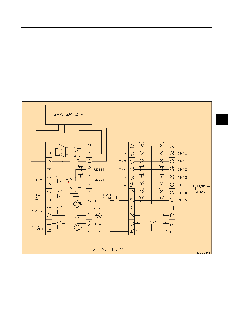
1MRS751880-MEN
LIB 500
253
LIB 500 Configuration Manual
Configuration Guide
8. System self supervision
8
• Other command procedures does not use the parallel queue 5
8.14.6.
Changes in version 2.0
• The program is ported to the NT platform
The procedure did not activate the group alarm when an new alarm appeared on a
channel if the channel already was acknowledged (read the led did not start flashing
again).
The procedure activated the SPACOM device alarm even if the status was OK. The
reason was that other status's than 0 is OK (13253,13258) in the SPA protocol (using
SPA protocol in NET).
8.14.7.
Connection diagram for SACO annunciator
)LJ &RQQHFWLRQGLDJUDP
8.14.8.
Reference documentation
SACO 16D1 and SACO 16D3 manuals.

254
1MRS751880-MEN
LIB 500 Configuration Manual
LIB 500
8. System self supervision Configuration Guide
8.15.
System Self Supervision and communication gateways
8.15.1.
Transferring supervision information from COM 500 to network
control center
Transferring of system supervision information from COM 500 to Network Control
Center (NCC) is also possible. The information, which is to be sent to the NCC is
the derived information from the original supervision information received from the
communication unit e.g. PC-NET to COM 500. If e.g. System Self Supervision has
received an event REXP_DEVICE_SUSPENDED to the COM 500, this leads to the
situation that e.g. alarm process object for System Self Supervision is updated in
COM 500. When this occurs, COM 500 can then be used for sending the updated
value to the NCC indicating that alarm has occurred in COM 500 related to that
station.
Information is transferred from COM 500 to the NCC by utilizing existing event and
alarm handling process objects stored in application, where COM 500 is running
together with System Self Supervision functionality. It is recommended to use IEC
60870-5-101 protocol between COM 500 and NCC, if applicable. The event and
alarm handling process objects created by the Supervision Base are routed from
COM 500 application to the NCC by using addresses defined into Signal Cross-
References Tool during COM 500 signal engineering. In the NCC there has to be the
corresponding process objects which receive the supervision information on the
same addresses. The naming and index conventions for event and alarm objects can
be found from the System Self Supervision Configuration Manual, Section 8.3.4.7.
In practise, either event and alarm process objects or indication process objects as
well can be routed from COM 500 application to the NCC. In case of LON Clock
Master (SLCM), whether the clock status information is to be transferred to the NCC
level also, the routing points for SLCM may be routed without event activation in
the NCC. Disabling of event activation in the NCC is applicable, if NCC is based on
MicroSCADA Technology. If RP 570 protocol is used between COM 500 and NCC,
only the event recording process objects should be routed for transferring alarm or
event handling information to the NCC.
Please note that the process objects for event and alarm handling are constructed into
the process database of COM 500 application according to received diagnostics
information from the communication unit, e.g PC-NET. Thus, the number of event
and alarm handling process objects in COM 500 is increased during continuous
communication between process devices and communication unit. Because of this,
it is not recommended to do the routing immediately for event and alarm handling
process objects in COM 500, when System Self Supervision functionality is
enabled.
If there is need to collect some events inside certain alarm group in COM 500, then
it is possible to route these alarm handling process objects related to that specific
alarm group only. It means that first some alarm group has to be defined in COM
500, e.g. with name "Station suspensions" together with its address information.
Then all the appropriate alarm handling process objects are cross-referenced to that
specific alarm group during COM 500 signal engineering. No address definition is
required, if only alarm group information is transferred to NCC. Note that it is also

1MRS751880-MEN
LIB 500
255
LIB 500 Configuration Manual
Configuration Guide
8. System self supervision
8
possible to route both the accurate event information and alarm group information
by defining both address and alarm group definitions. The group alarm state is sent
to the NCC from COM 500, when one of its alarm handling process objects receives
alarm state (alarm group becomes alarming in NCC) or all the alarm handling
process objects receives their normal state (alarm group is not alarming in NCC).
8.15.2.
Configuration of System Self Supervision in network control
center
When supervision information is sent to the Network Control Center, the
configuration of NCC has to include related process objects for receiving the
updated values through event and alarm handling mechanism from COM 500. For
each defined process object, the consistency between COM 500 and NCC signal lists
is required, otherwise the information is not received into NCC. The updated value
from COM 500 to NCC, can be then utilized in the NCC to define the state of this
appropriate process object to be shown in Event or Alarm Lists as an supervision
information event.
Please note that if the system supervision picture is required in the NCC, also the
directory of /SUPERV under COM 500 application should be copied under to the
NCC application. Copying is applicable, if NCC is based on MicroSCADA
Technology.


LIB 500
Index
Configuration Guide
Index
Page
$
Action
Activation in the report database
................................................................................... 43
Active
Active SLCM state
Active status, SLCM
Active status, SLCM 1
................................................................................................ 150
Active status, SLCM 2
................................................................................................ 150
Alarm
Alarm class
Alarm handling mechanism
........................................................................................... 55
Alarm limit
Alarm list menu
Alarm List started from the Reports menu
.................................................................... 55
Alarm text line
Alarm type color numbers
............................................................................................. 63
Alarm, acknowledged
Alarm, unacknowledged
.............................................................................................. 176
APL:BLA
APL:BSV45
APL_EVENT
...........................................135
APL_INFO
APL_INFO_POSITION
......................................................................................197
APL_NUMBER
APL_NUMBERS
................................................................................................189
APL_STATUS_CHECK_INTERVAL
........................................................................ 172
Application language
Application local memory pools state
.................................................................194
Application local queues state
.............................................................................194
Application object attribute
........................................................................................... 44
Application object presentation
...........................................................................196
Application picture
..................................................................................................11
Application shadowing phase
..............................................................................194
Application state
Attribute
Attribute Folder
Attribute settings
Authority group
Authority level
Authorization group
................................................................................................44
Authorization level
..................................................................................................59
AUTHORIZATION_
.................................................................................. 183
AUTHORIZATION_GROUP
Automatic printout
%
B_MONITOR
B_MONITOR index
B_MONITOR process objects
.................................................................................... 187
B_SSS_MECH_IN_USE
....................................................................................141
Bay name
1MRS751880-MEN
LIB 500 Configuration Manual

1MRS751880-MEN
LIB 500 Configuration Manual
LIB 500
Index
Configuration Guide
Binding output network variables
............................................................................... 146
Bounded network variable
.......................................................................................... 148
BSI_APL.DAT
BSI_APL.HLP
BSI_APLI.PIC
BSI_APLT
BSI_APLT.PIC
BSI_MON2.DAT
BSI_MON2.HLP
BSI_MONI.PIC
BSI_MONT
BSI_MONT.PIC
BSI_NET2.DAT
BSI_NET2.HLP
BSI_NETI_L.PIC
BSI_NETI_M.PIC
BSI_NETL.DAT
BSI_NETL.HLP
BSI_NETLI.PIC
BSI_NETLT
BSI_NETLT.PIC
BSI_NETT
BSI_NETT.PIC
BSI_PRINT2.DAT
BSI_PRINT2.HLP
BSI_PRINTI.PIC
BSI_PRINTT
BSI_PRINTT.PIC
BSI_SLCM.DAT
BSI_SLCM.HLP
BSI_SLCMI.PIC
BSI_SLCMT
BSI_SLCMT.PIC
BSI_STA2.DAT
BSI_STA2.HLP
BSI_STAI_L.PIC
BSI_STAI_M.PIC
BSI_STAI_S.PIC
BSI_STAT
BSI_STAT.PIC
BSI_SYS2.DAT
BSI_SYS2.HLP
BSI_SYSI_L.PIC
BSI_SYSI_M.PIC
BSI_SYST
BSI_SYSTT.PIC
BSU_APL.HLP
BSU_DLG2A.PIC
BSU_DLGA.PIC
....................................................... 186
BSU_DLGB.PIC
...............................................186
BSU_DLGC.PIC
BSU_MON2.HLP
BSU_NET2.HLP
BSU_NETL.HLP

1MRS751880-MEN
LIB 500
Index
LIB 500 Configuration Manual
Configuration Guide
BSU_PRINT2.HLP
BSU_SLCM.HLP
BSU_SLCM2.HLP
BSU_STA2.HLP
BSU_SWD_C1:C
BSU_SWD_C2:C
BSU_SYS2.HLP
BSWAPLIAPL
BSWNETILIN
BSWNETINET
BSWNETXNET
BSWPRIIPRI
BSWPRIXPRI
BSWSTAILCM
BSWSTAISTA
BSWSTAXSTA
BSWSYSISYS
&
Cascade items
Changing of menu item in template 1 and 2
................................................................. 58
Clock status object presentation
.................................................................................. 232
Color laser printer i.e. hardcopy printer object presentation
....................................... 240
Color matrix event printer object presentation
............................................................ 240
Color palette
Communication unit line object presentation
.............................................................. 218
Communication unit line state
..................................................................................... 222
Communication unit redundancy state
........................................................................ 214
Communication unit state
............................................................................................ 214
Configure Function button
......................................................................................27
Configuring Picture Functions
...................................................................................... 18
Configuring Representations
......................................................................................... 19
Connection to GPS object presentation
....................................................................... 232
Connections between network variables
..................................................................... 146
Consistency Check Time (CT) attribute
..............................................................148
Control (1)
Conversion
Copy the standard function
.......................................................................................... 119
'
DARK GREY
Data file
Database object
DCD supervision
.................................................................................................145
DCP-NET object presentation
..................................................................................... 204
Default settings
DESCRIPTIVE_TEXT
............................................................................................... 155
Desktop large size (3-D) object presentation
.............................................................. 188
Desktop large size object presentation
........................................................................ 188
Desktop medium size (3-D) object presentation
......................................................... 188
Desktop medium size object presentation
................................................................... 188
Device name
Device/apparatus name
........................................................................................139
Diagnostic Interval (DI) attribute
............................................................... 148

1MRS751880-MEN
LIB 500 Configuration Manual
LIB 500
Index
Configuration Guide
Diagnostic Interval attribute
................................................................................ 145
Directories
Directory structure
Double monitor object presentation
............................................................................ 183
(
Edit dialog
Edit Menu Item dialog
Edit OI dialog
Edit the standard function index file
........................................................................... 119
Element
Element STATUS
Element STATUS > 0
ENABLE_ALARM
ENABLE_EVENT
ENABLE_LOG
ENABLE_STATION_EVENTS
................................................................................. 171
ENABLE_STATION_MESSAGES
............................................................................ 171
Enabling a menu item
Engineering (2)
Engineering menu
Event activation
Event log
Event text line
EXT_WD_APL_NR
.......................................................................... 189
)
Faulty_Bit_Numbers
Faulty_Bit_Values
FILE_NAME_OF_CONF_INI
................................................................................... 169
FILE_NAME_OF_EVENT_INI
................................................................................. 169
FILE_NAME_OF_FILTER_INI
................................................................................. 169
FILE_NAME_OF_LANG_INI
................................................................................... 169
FILE_PATH
Filter configuration
................................................................................................. 57
Filter Preconfigurations dialog
................................................................................ 57
Filters
Filters dialog
FORM4BSAI.PIC
FORM4BSAI.TXT
FORM4BSBI.PIC
FORM4BSBI.TXT
*
General station object presentation
............................................................................. 227
Generator
Global memory pool state of a Base System
...................................................... 194
Global time-out value
GREEN
GREY
Ground Terminal
Grounded

1MRS751880-MEN
LIB 500
Index
LIB 500 Configuration Manual
Configuration Guide
+
HB
HDB files
Help Part
History buffer
History database
History log activation
History logging Policy
HL-attribute
Horizontal scroll bar
HOT_STAND_BY
.............................................................................189
HP
,
Index
INDEX4_B11.TXT
.......................................... 186
Infeeding lines
Installation of standard functions
.................................................................................. 12
Installation Wizard
Installing the Application Library functions
................................................................... 1
Installing the software
Invalid value
Item
Item action program
/
LABEL
.................................... 183
LABEL_POSITION
Language conversion
Language versions
Language-dependent logical paths
................................................................................ 23
Layout
Length of each text column
........................................................................................... 65
Line element
Line Indicator
Link Type (LK) –attribute
...................................................................................145
Link Type attribute
..............................................................................................146
LOCAL
LOCAL_IX
LOCAL_LN
LOCAL_REMOTE
LOG files
Log_Prefix_of_SLCM_Bit_
........................................................................................ 167
LOG_SEPARATOR
LON Clock Master card object presentation
.......................................................232
LON Star Coupler
0
M scope color definitions
.............................................................................................. 73
MAGENTA
Main voltage states
Matrix event printer object presentation
.............................................................240
Matrix event printer, old object presentation
............................................................... 240

1MRS751880-MEN
LIB 500 Configuration Manual
LIB 500
Index
Configuration Guide
MAX_LENGTH_OF_LOG
........................................................................................ 172
Maximum number of nodes
.......................................................................................... 92
Menu action definitions
.......................................................................................... 30
Menu configuration
Menu Configuration tool
............................................................................................... 60
Menu definitions
Menu items
MFL object presentation
............................................................................................. 204
MI
...............................................................................................221
MI (message Identification)
........................................................................................ 213
Modify the new standard function to the new size
..................................................... 119
Monitor language
MONITOR_ADDRESS
.............................................................................................. 184
MONITOR_HOST_NAME
........................................................................................ 184
MONITOR_TYPE
Motor, Capacitor, Reactance
......................................................................................... 81
MS
..............................................................................................221
MS (Message System)
................................................................................................ 213
M-scope colors
1
Name
NET
NET_LINE_NR
................................................217
NET_NODE_NR
.............................205
NET_SA
NET_STATUS_CHECK_INTERVAL
........................................................................ 172
NET_TYPE
NETP_SYSTEM_INITIALIZED
............................................................................... 161
No audible activation
NODE_NUMBER
............................................................................. 189
Nodes
Normal items
Normal state, in use
Not in use
Not sampled
Not updated
NV index 7 nv_invalid_ref
......................................................................................... 147
NV_CLOCK_STATUS_1
................................................. 148
NV_CLOCK_STATUS_2
...........................................................................148
2
Object
Object id
Object identification (OI) attribute
........................... 188
Object identification, OI
............................................................................................... 43
Object text
Object text, OX
OI-attribute
Old SYS_BASCON.COM
.......................................................................................... 142
Order of the alarms on the list
....................................................................................... 65
OS_EVENT
................................................................................................135
Output Synchronization (OS) -attribute
.............................................................. 145
Output Syncronization attribute
.......................................................................... 145

1MRS751880-MEN
LIB 500
Index
LIB 500 Configuration Manual
Configuration Guide
OX-attribute
3
Parameter
Passive
PATH4_B11.TXT
............................................. 187
PC_NETS.COM
PC-NET object presentation
................................................................................204
PEER_NODE_NR
...............................................................................................205
PF
Picture Editor
Picture element
Picture function
................................................................................................ 12
Picture function name
....................................... 183
Picture Functions button
..........................................................................................27
Position of each text column
......................................................................................... 65
Power flow
Preconfigured filter
Primary side
Printer state
PRINTER_CONN_TYPE
...................................................................................241
PRINTER_NR
PROCESS ALARMS
Process object
Process Object Tool
Programs Folder
Progress bar
Progress indicator
5
RED
RED, FLASHING
REDUNDANCY
.................................................................................................205
REDUNDANCY_INFO
......................................................................................206
REDUNDANCY_INFO_ POSITION
................................................................206
Redundant SLCM diagnostics
..................................................................................... 148
Redundant SLCM state
............................................................................................... 238
Redundant status, SLCM
............................................................................................. 148
Redundant status, SLCM 1
.......................................................................................... 150
Redundant status, SLCM 2
.......................................................................................... 150
Registration
REMOTE
Remote alarm
Representation Tool
RER 111
REx type of station object presentation
....................................................................... 223
REXP_DEVICE_SUSPENDED
................................................................................. 254
RTU terminal status
RTU type of station object presentation
...................................................................... 224
6
SACO CONFIGURATION
......................................................................................... 251
SACO type of station object presentation
................................................................... 224
SCIL files
.................................................................................................................... 128

1MRS751880-MEN
LIB 500 Configuration Manual
LIB 500
Index
Configuration Guide
SCIL method for disabling a menu item
....................................................................... 31
SE
...............................................................................................221
SE (System Messages Enabled)
.................................................................................. 213
Secondary side
Selecting Functions for Installing
................................................................................... 4
Separators
Setting dialog
Settings dialog
Settings dialogs
Settings for existing filters
............................................................................................ 57
Single line pictures
Single monitor (big) object presentation
..................................................................... 183
Single monitor (small) object presentation
................................................................. 183
SLCM_NR
SNVT_state
SRIO type of station object presentation
.................................................................... 224
SSS_APLINIT.SCL
SSS_APLOBJ.SCL
SSS_INIT.SCL
SSS_LOGINIT.SCL
SSS_MGR.MOD
SSS_MGR2.MOD
SSS_REV.SCL
SSS_SETUP.SCL
............................................................................... 152
SSS_UPDATE.SCL
SSSCONF.INI
SSSEVENT.INI
SSSFILTER.INI
SSSLVIEWER.INI
SSSLVIEWER.VSO
SSSTEXTS.INI
SSSTexts.ini
STA_UN
Standard Configuration Tool (SCT)
..................................................................15
Standard function
....................................................................................... 13
Standard Function Installation Tool (IT)
....................................................................... 96
Standard function picture
............................................................................................ 120
Standard Part
Starting Installation
Static
Station name
..................................................................................................55
Station state
Station, general object presentation
............................................................................ 223
STATION_NR
STATION_TYPE
................................................................................................ 225
Status
Status codes
Status_ added status code number
............................................................................... 161
String lengths
SYS
SYS:BTI attribute
SYS_AA
SYS_AE
SYS_AI

1MRS751880-MEN
LIB 500
Index
LIB 500 Configuration Manual
Configuration Guide
SYS_APLE
SYS_APLE1
SYS_APLE2
SYS_APLER
.............................................................................................. 159
SYS_APLH
SYS_APLH1
SYS_APLH2
SYS_BASCON.COM
...............................................128
SYS_CNTR
SYS_EVENT
SYS_MSG_DCP_NET
............................................................................................... 163
SYS_MSG_LINE_1
SYS_MSG_LINE_12
SYS_MSG_LINE_14
SYS_MSG_LINE_16
SYS_MSG_LINE_25
SYS_MSG_LINE_27
SYS_MSG_LINE_29
SYS_MSG_LINE_30
SYS_MSG_LINE_31
SYS_MSG_LINE_32
SYS_MSG_LINE_33
SYS_MSG_LINE_35
SYS_MSG_LINE_4
SYS_MSG_LINE_43
SYS_MSG_LINE_7
SYS_MSG_NET_MFL
............................................................................................... 163
SYS_MSG_NET_PCNET
........................................................................................... 161
SYS_MSG_PC_NET
SYS_MSG_PRINTERS
.............................................................................................. 164
SYS_MSG_SLCM
SYS_MSG_STA_DNP
................................................................................................ 164
SYS_MSG_STA_IEC
SYS_MSG_STA_LCU
................................................................................................ 164
SYS_MSG_STA_LMK
............................................................................................... 163
SYS_MSG_STA_PLC
................................................................................................ 164
SYS_MSG_STA_REX
................................................................................................ 163
SYS_MSG_STA_RTU
................................................................................................ 164
SYS_MSG_STA_SPA
SYS_MSG_STA_SPI
SYS_NA
SYS_NE
SYS_NETLMR
SYS_NETMR
............................................................................................. 159
SYS_NETSR
......................................................................................159
SYS_NI
SYS_OA
SYS_OE
SYS_OI
SYS_OSER
SYS_PA
SYS_PE
SYS_PI
......................................................................................159

1MRS751880-MEN
LIB 500 Configuration Manual
LIB 500
Index
Configuration Guide
SYS_SA
SYS_SE
SYS_SI
SYS_SLCMR
..............................................................................................159
SYS_SSSINI
SYS_SSSREV
SYS_SSSRT
SYS_STAMR
..................................................................................... 159
SYS_SYSER
...............................................................................................159
SYS_UPOER
System Information
System message receiving, Active SLCM state
.......................................................... 238
System message receiving, communication unit line state
......................................... 222
System message receiving, communication unit redundancy state
............................ 214
System message receiving, communication unit state
................................................ 214
System message receiving, printer state
..................................................................... 247
System message receiving, Redundant SLCM state
................................................... 238
System message receiving, RTU terminal status
........................................................ 230
System message receiving, station state
............................................................. 230
7
Template 1
Template 2
Templates
Test Dialog
Text column positions
Text columns
Text indicating the alarm status
..................................................................................... 54
Text settings limits
Time stamp
TIMEOUT_LENGTH
Tool Manager
Tools Folder
Topology Generator (TG)
............................................................................................. 69
Tower model (3-D) object presentation
...................................................................... 191
Tower model medium size (3-D) object presentation
................................................. 188
Tower model medium size object presentation
........................................................... 188
8
U_WRITE_DEVICE_INFO
....................................................................................... 206
UNDEF_PROC
Unknown
Updating monitor pictures
............................................................................................ 43
User authorization
USER DEFINITIONS
User Interface folder
User language
User Management picture
............................................................................................. 66
9
Value
Variables
Vertical scroll bar
........................................................................................................ 121
View(0)

1MRS751880-MEN
LIB 500
Index
LIB 500 Configuration Manual
Configuration Guide
Voltage source
:
Welcome! dialog
WHITE
WRITE_DEVICE_INFO

Document Outline
- Installation of LIB 500
- Introduction
- Backbone
- Event list
- General
- Events
- Application engineering information
- Alarm list
- Busbar Coloring
- Component library
- System self supervision
- General
- System Self Supervision overview
- Supervision base general
- Project specific engineering
- System monitoring general
- Monitor
- Base system
- Application
- Communication unit
- Communication unit line
- Station
- LON Clock Master (SLCM)
- Printer
- SACO watch dog function
- System Self Supervision and communication gateways
Wyszukiwarka
Podobne podstrony:
LIB 510 Configuration Manual
LIB 500 Operator s Manual
LIB 510 Operator s Manual
Inter MR 150 300 500 pwr Service Manual
Canon EF 500 4 0 L IS USM Repair Manual
LIB 510 MV Process Configuration
Manuale configurazione router ( Sitecom PPPoE ) (1)
Jvc XVS 500 BK Service Manual 3
LIB 510 MV Process Operator s Manual
Manual Nokia 500 Auto Navigation PL
GK 500 MANUAL
PANsound manual
als manual RZ5IUSXZX237ENPGWFIN Nieznany
hplj 5p 6p service manual vhnlwmi5rxab6ao6bivsrdhllvztpnnomgxi2ma vhnlwmi5rxab6ao6bivsrdhllvztpnnomg
BSAVA Manual of Rabbit Surgery Dentistry and Imaging
Okidata Okipage 14e Parts Manual
Bmw 01 94 Business Mid Radio Owners Manual
więcej podobnych podstron