w w w . r m s p l . c o m . a u
www.rmspl.com.au
rms
rms
4M400 | K | 15/08/2013
4M400
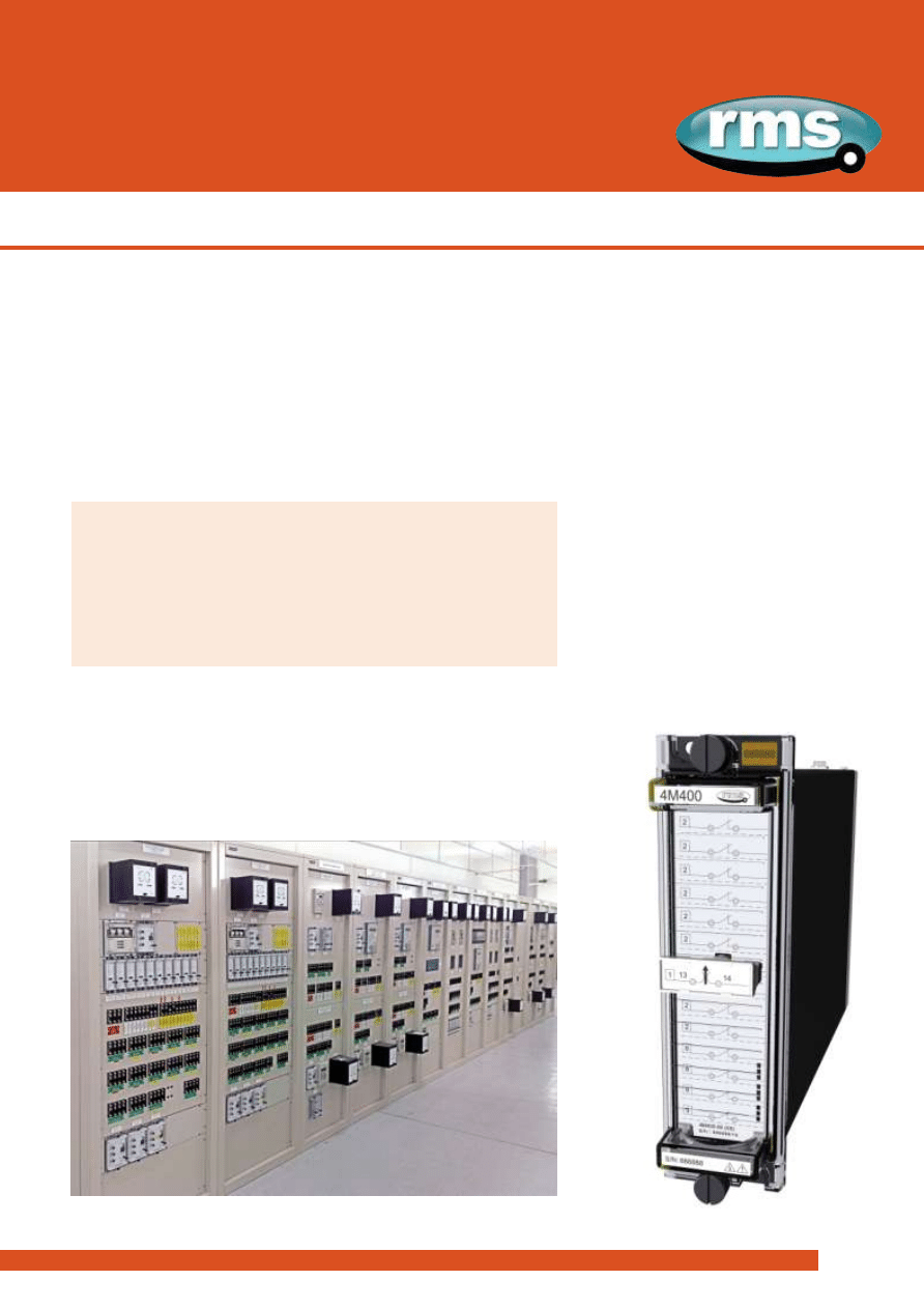
Test Block System
Flexible and high performance test block system with a focus on
operator safety. Suitable for application on a wide range of
protection relay panels.
>
Finger safe test sockets
>
Automatic CT shorting
>
14 independent test groups
>
Custom specified test circuits
>
Made in Australia
T E S T B L O C K S | T E S T P L U G S | T E S T L E A D S
AUXILIARY | TRIPPING | SUPERVISION
Introduction
Product name
4M400
2C73
rms
rms
2
3
w w w . r m s p l . c o m . a u
www.rmspl.com.au
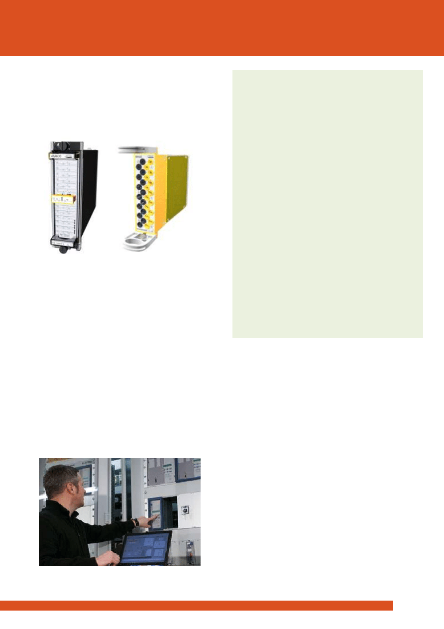
System Components
>
14 test circuits may be specified in any configuration
>
‘Finger safe’ test sockets
>
One standard model suits all 4M400 Test Block versions
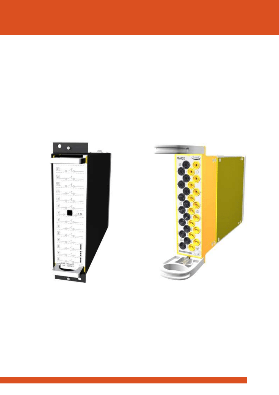
4M400 Test block
4M420 Multi finger test plug
Features
>
14 independent test groups may be specified
with any combination of circuit types
>
Automatic shorting of CT circuits completed in
the test block - No test links or operator
intervention required
>
Isolation plug provides sequential circuit
isolation timing in three (3) stages
>
‘Finger safe’ test sockets suit standard or
shrouded type 4mm banana plugs for direct
access to the protection or measurement
scheme
>
Clear and concise front panel circuit
identification
>
Test plug fitted with insertion handle and thumb
screw retention system to enhance operator
safety and system security
>
Side label instructions on test plug for changing
from normal service to the test condition
>
High current / voltage rating
>
Made in Australia
Application
Test blocks enable test technicians to quickly and safely isolate
protection relays so that test signals may be injected and
system performance verified.
There are a number of advantages in performing injection tests
at the protection relay panel:
>
Reduction in down time of the equipment under test
>
Testing does not cause disturbance to wiring, terminals or
equipment settings
>
Existing auxiliary supply to the equipment under test may
be isolated
The 4M400 Test Block is designed as a general-purpose
isolation and test signal injection point. ‘Finger safe’ sockets
are employed to improve operator safety and suit 4mm
shrouded ‘finger safe’ type banana plugs.
Equipment under test need only be removed for servicing if
problems are detected or for routine maintenance.
Where more than 14 test circuits are required refer to the
4M402 model that provides 28 test circuits.
rms
rms
3
3
Functional Description
Product name
4M400
2C73
w w w . r m s p l . c o m . a u
www.rmspl.com.au
Description
The 4M400 Test Block is an evolution of our popular 4M300
system. The main difference is that each of the fourteen (14)
test groups may be specified at time of order to provide
automatic CT shorting and sequential circuit to suit specific
protection schemes:
>
Stage 1 isolation
>
CT shorting
>
Stage 2 isolation
The main advantage of this approach is the improved level of
safety and security afforded to the CT circuits. This is because
the CT shorting function takes place within the 4M400 Test
Block irrespective of the CT circuit position. In many test block
systems the CT shorting is only accomplished when the Test
Plug is inserted which leaves open the possibility of a CT circuit
becoming open circuit due to the CT shorting links being
omitted or in the wrong position. This potential problem is
negated in the 4M400 and allows a single model 4M420 Test
Plug to be employed for all 4M400 Test Block configurations.
Each test circuit is connected to a separate pair of terminals at
the rear of the case. During normal operation of the associated
protection equipment, each terminal pair is connected via a
circuit-shorting link.
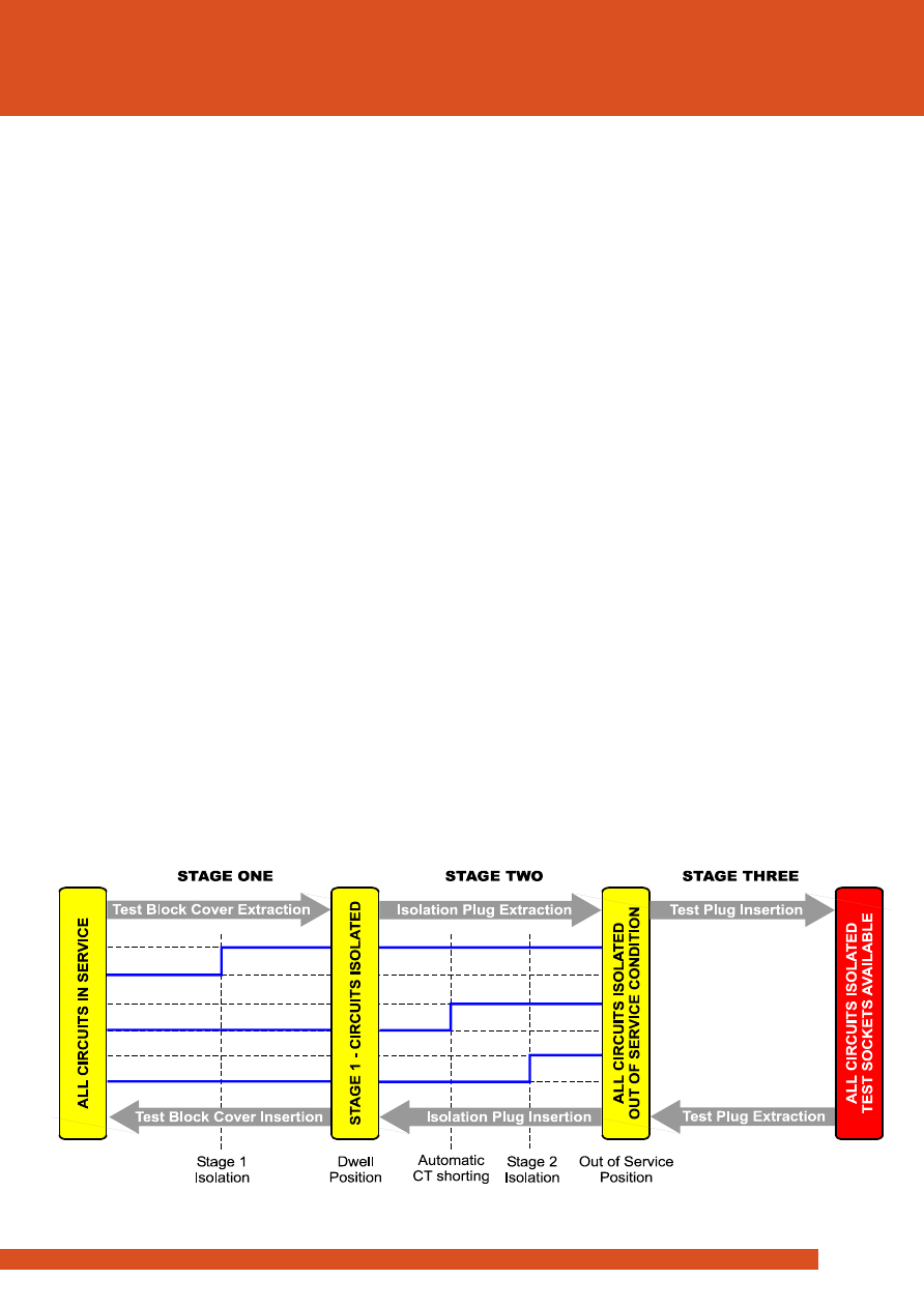
Changing the 4M400 Test Block from the normal service
condition occurs in three (3) stages as depicted in the timing
diagram figure 1.
Where more than 14 test circuits are required such as in EHV
transmission protection panels, the 4M402 Test Block with 28
test circuits may be employed.
Test Circuit Access
Access to the circuits, for testing purposes, is achieved in a
three stage process.
STAGE ONE
Test Block Cover Extraction
Isolation
Isolation of Stage 1 circuits
STAGE TWO
Isolation Plug Extraction
CT Shorting
Automatic shorting of all CT circuits
Isolation
Isolation of Stage 2
Isolation of CT circuits
STAGE THREE
Test Plug Insertion
Insertion 4mm Test Sockets available
The above procedure should be completed in the reverse order
to place the protection system back in service.
Insertion of the Test Plug type 4M420 connects the live side
circuits to the 4mm yellow test sockets. The equipment side
circuits are connected to the 4mm black test sockets. Each test
socket is identified by a number, which corresponds to the
numbered terminal on the rear of the case when the Test Plug
is inserted. Refer to figure 10.
Figure 1: Timing diagram of circuit isolation and CT shorting
rms
rms
4
3
Safety Features
Product name
4M400
2C73
w w w . r m s p l . c o m . a u
www.rmspl.com.au
Automatic CT Shorting
In traditional test block systems CT shorting is achieved by the
operator manually fitting shorting links to the appropriate
positions before inserting the test plug. This can lead to serious
errors due to incorrect or poorly interpreted wiring diagrams.
The 4M400 Test Block system employs a fool proof method of
CT shorting. When the 4M400 Isolation Plug is removed the CT
shorting is accomplished automatically within the test block
irrespective of the CT position or test block configuration. The
4M420 Test Plug does not require any special configuration
before insertion as the CT shorting positions have already been
specified at the time of order to suit a particular wiring
arrangement.
Test Block Polarization
Where conventional test block wiring schemes are employed in
a protection panel, sub-station or indeed across a power utility
network, there exists the possibility of a test plug being inserted
into the wrong test block. The 4M400 Test Block avoids the
potential for operator error as it incorporates a polarization pin
so that only the 4M400 Isolation Plug and 4M420 Test Plug may
be inserted.
Test Lead Insertion
Before use the insulation of the flying leads should be visibly
checked for damage.
Flexible banana test leads with shrouded plugs are
recommended for operator safety. 2.5mm2 multi-strand wire
with PVC insulation is recommended for adequate current
rating and flexibility.
Test Plug Insertion
To avoid high voltage shock hazard external CT circuits must
NOT be open circuited.
Insertion of the 4M420 connects the live side circuits to the
YELLOW test sockets on the front panel. The equipment side
circuits are connected to the BLACK test sockets on the front
panel. Each test socket is identified by a number, which
corresponds to the numbered terminal on the rear of the case
when the Test Plug is inserted.
Safety Overview
While providing considerable convenience and efficiencies to
system testing, test block systems must provide a high degree
of safety. This section describes the key design features
employed in the 4M400 test block system to enhance operator
safety.
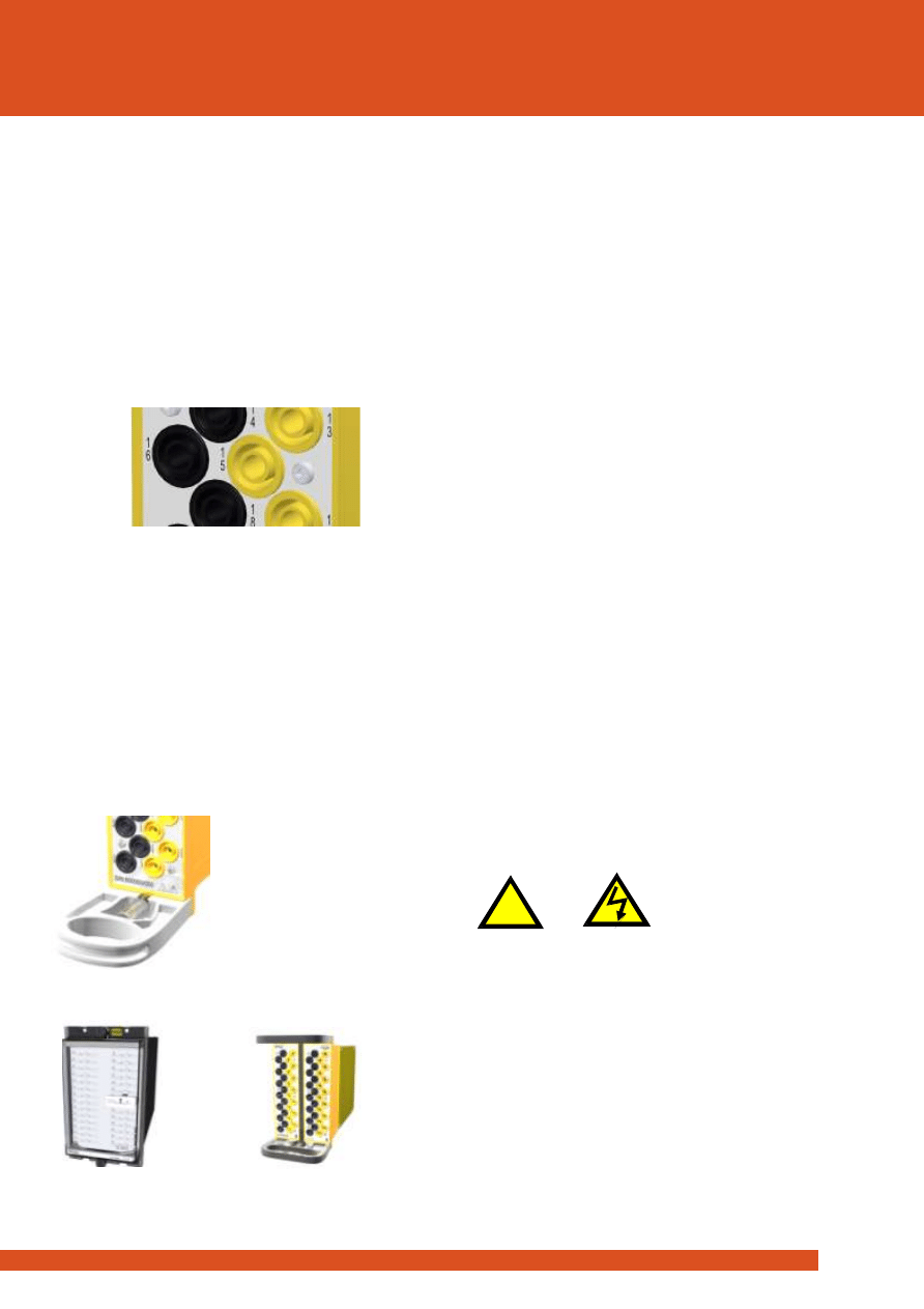
Finger Safe Test Sockets
BLACK
- even numbered equipment side sockets
YELLOW
- odd numbered live side sockets
Figure 2:
Close up view of the ‘finger safe’ test plug sockets
that accept standard 4mm shrouded test plugs
The 4M420 Test Plug employs ‘finger safe’ test sockets. This
allows the use of shrouded ‘finger safe’ banana plugs to greatly
reduce the possibility of an operator coming into contact with
any part of the test circuit.
Test Plug Handles
The 4M420 employs handles at the top and bottom of the plug
assembly to ensure the operators hand is well separated from
the test sockets during insertion. Retention thumb screws are
provided at the top and bottom of the test plug to avoid
inadvertent removal of the plug during testing.
28 Test Circuit Versions
4M402 Test block
4M422 Multi finger test plug
!
rms
rms
5
3
Functional Description
4M400
2C73
w w w . r m s p l . c o m . a u
www.rmspl.com.au
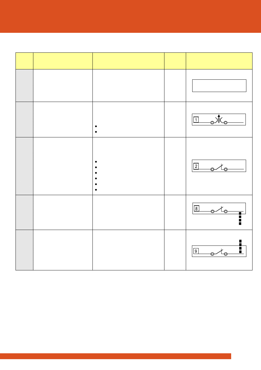
Type
Description
Function
Timing
Stage
Front Panel Labeling
0
Blank circuit
To allow additional space for labeling
on the front panel and isolation to
adjacent test circuits. May be
specified where less than 14 test
circuits are required.
N/A
1
Stage 1 isolation cassette
This circuit type is isolated at Stage 1
as the front cover is removed from
the Test Block. Use to provide:
Isolation of auxiliary supply
Isolation of trip circuits
1
2
Stage 2 isolation cassette
This circuit type is isolated at Stage 2
as the Isolation Plug is removed from
the Test Block. Use to provide:
Isolation of trip circuits
Remote ’Out of Service’ indication
Isolation of inter-tripping circuits
Isolation of watchdog alarms
Isolation of VT circuits
Isolation of I/O circuits
2
8
CT cassette with shorting bar
to the adjacent circuit below
Use for CT connections so that they
will be automatically shorted to the
adjacent CT circuit below.
After shorting, this circuit is isolated
at Stage 2.
Refer
Figure 2
9
Last CT cassette on a CT group
Use for the last CT connection in a
group so that it will be automatically
shorted to the adjacent CT circuit
above.
After shorting, this circuit is isolated
at Stage 2.
Refer
Figure 2
CUSTOM TEXT
(2 lines x 15 characters)
Table 1: Test circuit selection chart
Notes:
1.
Type 1 cassettes cannot be specified in adjacent positions.
2.
A maximum of four (4) CT cassettes may be specified in a single group.
3.
CT circuits must be specified with either cassette type 8 or 9.
rms
rms
6
3
Applications
Product name
4M400
2C73
w w w . r m s p l . c o m . a u
www.rmspl.com.au
CT Circuits
CT circuits must be specified with either cassette type 8 or 9.
CT circuits must not be wired to cassette types 0, 1 or 2 as this
will result in open circuit CT’s as the isolation plug is removed.
Figure 4: 4M420 Test Plug
Note ‘finger safe’ test sockets to accept
4mm shrouded test plugs
Recommended Wiring Layout
It is recommended that the Test Block is always wired with
connections to the protective relay or scheme made to the
EVEN numbered equipment side terminals. Connections to
other equipment, e.g. CT’s, VT’s and DC supplies, should be
made to the ODD numbered live side terminals on the Test
Block. This ensures that when the Test Plug is inserted, the black
sockets are connected to the isolated relay circuits and the
yellow sockets are connected to the potentially live supplies as
shown in figures 5 to 8.
Figure 3: Front Panel Layout
4M400-06 Test Block for a 3 Ph O/C and E/F application.
>
This image shows the 4M400 with the front cover
removed to isolate the Stage 1 circuits.
>
The Isolation Plug is in place so the CT’s and Stage 2
circuits are still connected.
>
The front label identifies each cassette type.
rms
rms
7
3
Applications
Product name
4M400
2C73
w w w . r m s p l . c o m . a u
www.rmspl.com.au
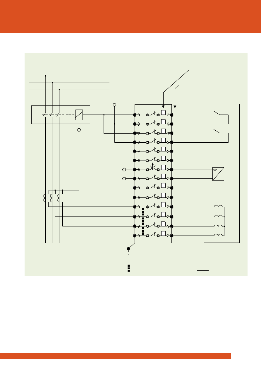
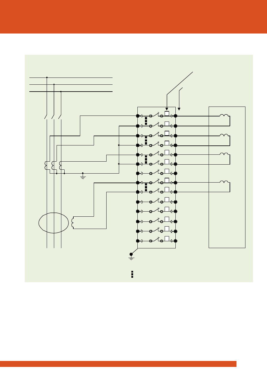
Figure 5: Application wiring example for a three phase overcurrent and EF protection scheme with auto CT shorting
Order code: 4M400-06- [22222212228889]
4M400-06 Test Block
(REAR VIEW)
CB
Protecti on scheme
Typical application for a three phase overcurrent & EF protection scheme
4M400-06
1
- Trip
+ Trip
Case e arth
Case terminal number
Test circuit type ( Order cod e per cir cuit)
V aux
27
2
6
5
4
3
8
7
1 0
9
1 2
11
1 4
13
1 6
15
1 8
17
2 0
19
22
21
2 4
23
26
25
28
A
B
C
Ia
Ib
Ic
E/F
DC
auxili ary
Trip
Trip
Automatic CT shorting bar engages
circuit is isolated
before
2
2
2
2
2
2
2
2
2
1
8
8
8
9
rms
rms
8
3
Applications
Product name
4M400
2C73
w w w . r m s p l . c o m . a u
www.rmspl.com.au
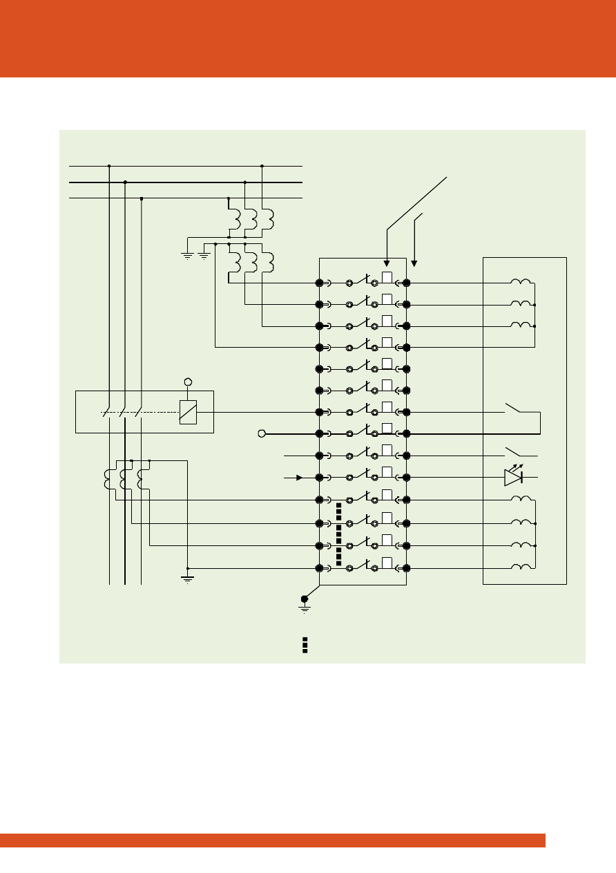
Figure 6: Application wiring example for a three phase directional O/C and E/F
or distance protection scheme with auto CT shorting
Order code: 4M400-07- [22222222228889]
Typical application for a three phase directional overcurrent & E/F or distance protection scheme
4M400-07 Test Block
(REAR VIEW)
CB
Protecti on scheme
- Trip
+ Trip
Case e arth
Case terminal number
Test circuit type ( Order cod e per cir cuit)
A
B
C
Ia
Ib
Ic
E/F
Trip
Out put
Input
Automatic CT shorting bar engages
circuit is isolated
before
Va
Vb
Vc
1
27
2
6
5
4
3
8
7
1 0
9
1 2
11
1 4
13
1 6
15
1 8
17
2 0
19
22
21
2 4
23
26
25
28
2
2
2
2
2
2
2
2
2
2
8
8
8
9
4M400-07
rms
rms
9
3
Applications
Product name
4M400
2C73
w w w . r m s p l . c o m . a u
www.rmspl.com.au
4M400-08 Test Bloc k
(REAR VIEW)
Protection scheme
Typical application for 3 Ph CT’s and core balance E/F CT
Case earth
Case term inal num ber
Test circuit type ( Order cod e per cir cuit)
Automatic CT shorting bar engages
circuit is isolated
before
1
27
2
6
5
4
3
8
7
1 0
9
1 2
11
1 4
13
1 6
15
1 8
17
2 0
19
22
21
2 4
23
26
25
28
8
9
2
8
9
2
2
8
2
9
2
8
2
9
4M400-08
A
B
C
E
I
I
I
(3Io)
b
a
c
Figure 7: Application wiring example for a three phase Cut’s and core balance E/F CT with auto CT shorting
Order code: 4M400-08- [89898928922222]
rms
rms
10
3
Applications
Product name
4M400
2C73
w w w . r m s p l . c o m . a u
www.rmspl.com.au
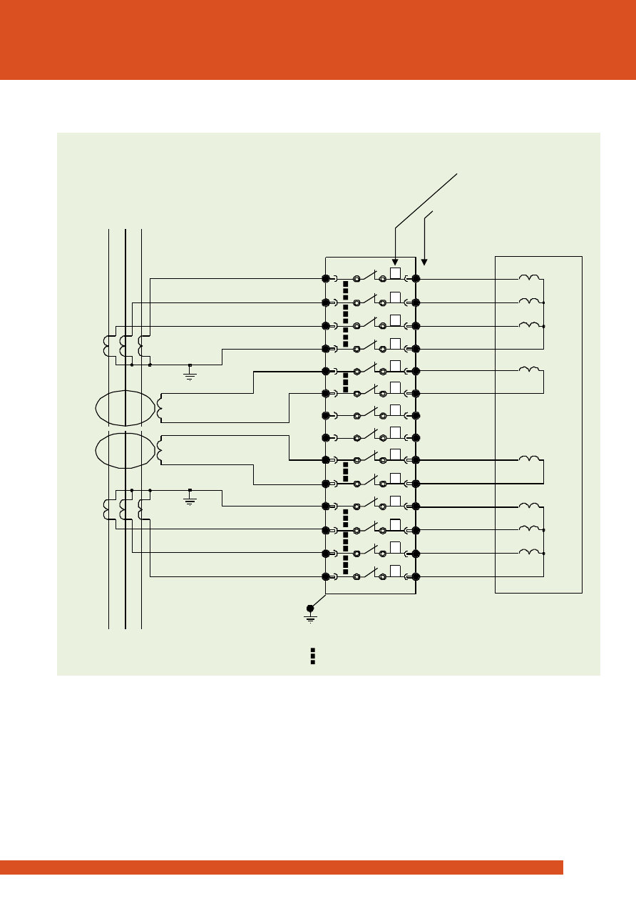
Figure 8: Application wiring example for differential protection of transformers with auto CT shorting
Order code: 4M400-09- [88898922898889]
4M400-09 Test Bloc k
(REAR VIEW)
Protection scheme
Typical application for differential protection of transformers
Case earth
Case term inal num ber
Test circuit type ( Order cod e per cir cuit)
A
A
B
B
C
C
Ia
Ia
N
N
E/F
E/F
Ib
Ib
Ic
Ic
Automatic CT shorting bar engages
circuit is isolated
before
1
27
2
6
5
4
3
8
7
1 0
9
1 2
11
1 4
13
1 6
15
1 8
17
2 0
19
22
21
2 4
23
26
25
28
8
9
2
2
8
9
8
8
8
8
8
8
9
9
4M400-09
rms
rms
11
3
Technical Data
Product name
4M400
2C73
w w w . r m s p l . c o m . a u
www.rmspl.com.au
4M400 Test Block
14 Equipment side terminals (Even terminal numbers).
14 Live side terminals (Odd terminal numbers).
14 Live sides to equipment side shorting links.
This arrangement provides for up to 14 independent circuits to
be connected.
4M420 Multi-Finger Test Plug
28 test sockets suitable for 4mm shrouded ‘finger safe’ type or
standard banana plugs.
Securing screws to retain the Test Plug during testing
operations.
Current Ratings
CT circuits and terminals
20A
continuous
400A
1s
Other circuits
10A
continuous
200A
1s
Case Type
2M28-S
Size 2continuous
28 terminals
Mounting
Flush
4U high rack mount
Individual Transport Packaging
1x 4M400 Test Block in a size 2 packing box
Size:
360 x 250 x 100mm
Weight: 1.7 Kg
Bulk Transport Packaging
10x 4M400 Test Blocks with inner packing in a shipping carton
Size:
470 x 430 x 350mm
Weight: 15 Kg
Typical pallet sizes (Add 15Kg for pallet)
2L x 3W x 2H
12 x shipping cartons per pallet
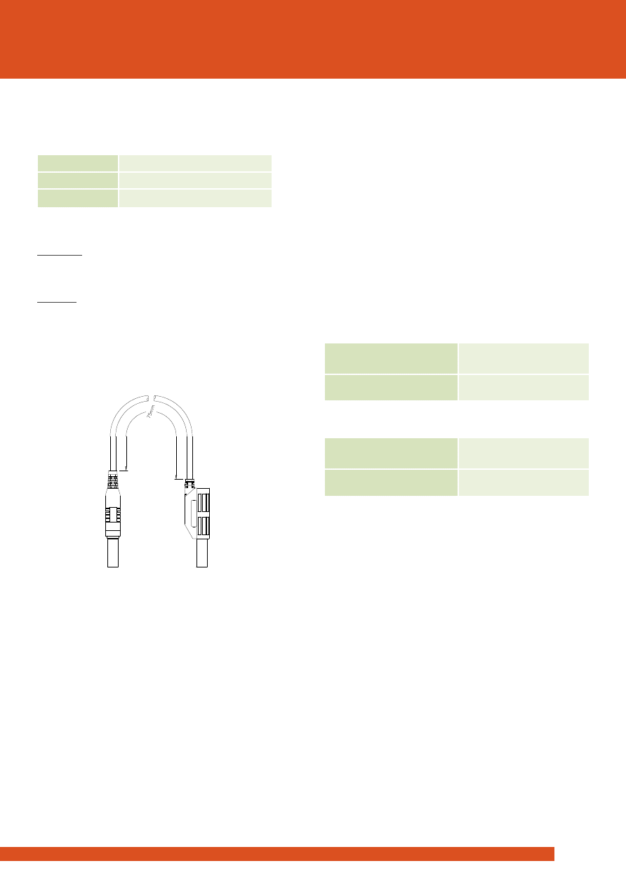
Shrouded Test Leads
Two types of shrouded ‘finger safe’ test leads are available:
Part Number
Description
310-230-075-1
Two ended test lead - 75mm
310-230-180-1
Two ended test lead - 180mm
Test Lead Plugs
Single Plug
The single plug is the most compact and may be plugged into
any test socket.
Dual Plug
The dual or ‘piggy back’ plug is larger and should be plugged
into the test sockets on the outside edge of the 4M420.
Figure 9:
Two ended test lead - short
P/N 310-230-075-1
75mm wire length version depicted

rms
rms
12
3
Compliance Data
Product name
4M400
2C73
w w w . r m s p l . c o m . a u
www.rmspl.com.au
Temperature
Standard
IEC 60068-2-1/2
Operating Range
-10 to +55 degrees Celsius
Storage Range
-25 to +70 degrees Celsius
Humidity
Standard
IEC 680068-2-78
Operating Range
40 degrees Celsius and 93% RH
non condensing
IP Rating
Standard
IEC 60529
Installed
IP5x
Vibration - Sinusoidal
Standard
IEC 60255-21-1 Class I
Vibration Response
0.5gn
≤5%
Vibration Endurance
1.0gn
≤5%
Shock and Bump
Standard
IEC 60255-21-2 Class I
Shock Response
5gn, 11ms
≤5%
Shock Withstand
15gn, 11ms
≤5%
Bump Test
10gn, 16ms
≤5%
Seismic
Standard
IEC 60255-21-3 Class I
Seismic Response
1gn
≤5%
Mechanical Classification
Durability
>105 operations at no load
Insulation – 4M400 - In Service
Standard
IEC 60255-5
Type
Level
Between any contact pair &
either adjacent contact pair.
2.0kV ac rms for 1 minute
Between all case terminals &
the case earth
5.0kV ac rms for 1 minute
Between any alternate
contact pair, provided that
the intermediate pair is not
used.
5.0kV ac rms for 1 minute
Insulation – 4M420
Standard
IEC 60255-5
Type
Level
Between any contact.
2.0kV ac rms for 1minute
Between any alternate
contact pair, provided that
the intermediate pair is not
used.
5.0kV ac rms for 1 minute
Insulation – 4M400 with 4M420 Fitted
Standard
IEC 60255-5
Type
Level
Between incoming &
outgoing contacts.
2.0kV ac rms for 1minute
Between all case terminals &
the case earth
5.0kV ac rms for 1 minute
rms
rms
13
3
Case Details
Product name
4M400
2C73
w w w . r m s p l . c o m . a u
www.rmspl.com.au
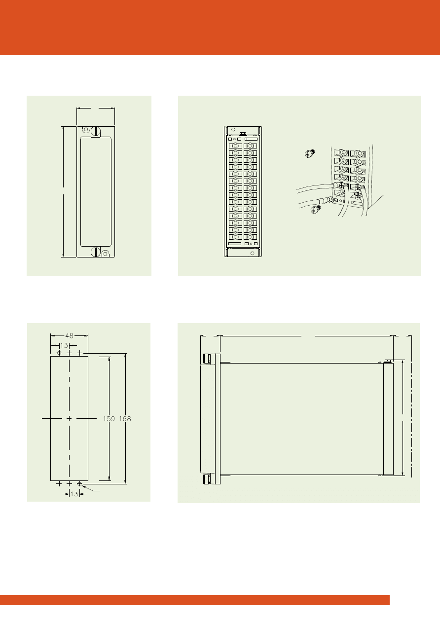
Rear View
Side View
Panel Cut-out
Front View
P/N 263-635-008
Screw lug 4mm (O/D 8.0mm MAX)
Wire 2.5mm MAX
2
1
2
27
28
51
177
217
27
25
157
4M400 Test Block
and draw out Isolation Plug
Drawing units: mm
Suits flush panel mounting &
4U high 19 inch rack frame
Figure 10: Case details
2 holes of 3.7
Order Codes
Product name
4M400
2C73
rms
rms
14
3
w w w . r m s p l . c o m . a u
www.rmspl.com.au
4M400 -
[ Equivalent cassette numbering details ]
Standard configuration 4M400-06 Figure 5
06
[2 2 2 2 2 2 1 2 2 2 8 8 8 9]
Standard configuration 4M400-07 Figure 6
07
[2 2 2 2 2 2 2 2 2 2 8 8 8 9]
Standard configuration 4M400-08 Figure 7
08
[8 9 8 9 8 9 2 8 9 2 2 2 2 2]
Standard configuration 4M400-09 Figure 8
09
[8 8 8 9 8 9 2 2 8 9 8 8 8 9]
4M400 - S -
Application specific version
S
Test Circuits Blank circuit
0 0 0 0 0 0 0 0 0 0 0 0 0 0
Stage 1 isolation circuit
1 1 1
1
1
1
1
1
1
1
1
1
1
1
Stage 2 isolation circuit
2 2 2 2 2 2 2 2 2 2 2 2 2 2
CT circuit with shorting bar to adjacent circuit below
8 8 8 8 8 8 8 8 8 8 8 8 8 8
The last CT circuit on a CT group
9 9
9
9
9
9
9
9
9
9
9
9
9
9
Order Code Limitations
1.
Type 1 cassettes cannot be specified in adjacent positions.
2.
A maximum of four (4) CT cassettes may be specified in a single group.
>
Test Plug
Only one version of the 4M420 Test Plug is required for use with all standard and special 4M400 Test Block versions:
4M420
Standard Test Blocks
Special Test Blocks
Compliance heading to go here
Cross Reference Chart
Shrouded Test Leads
RMS Codes *
MMLG-01
2RMLG-01
4M300-B **
MMLG-02
2RMLG-02
4M300-A **
-
4M400-06
MMLG-07
2RMLG-07
4M400-07
MMLG-08
2RMLG-08
4M400-08
-
2RMLG-09
4M400-09
-
4M400-S
Shrouded Test Leads
*
The 4M420 Test Plug is not compatible with the MMLG or the 2RMLG Test Blocks.
** Refer to the 4M300 Technical Bulleting for details on these versions where auto CT shorting is not required.
Part Number
Description
310-230-075-1
Two ended test lead - 75mm
310-230-180-1
Two ended test lead - 180mm
®
®
R e l a y M o n i t o r i n g S y s t e m s P t y L t d
6 Anzed Court
Mulgrave, Victoria 3170
AUSTRALIA
Ph: +61 3 8544 1200
Fax +61 3 8544 1201
Sales: rms@rmspl.com.au
www.rmspl.com.au
www.relays.com.au
Relay Monitoring Systems Pty Ltd
ISO9001 Quality Accreditation
RMS holds NCSI (NCS International Pty Limited) registration number
6869 for the certification of a quality system to AS/NZS ISO9001:2008.
Due to RMS continuous product improvement policy the information
contained in this document is subject to change without prior notice.
© 2013 Relay Monitoring Systems Pty Ltd ABN 76 052 484 483
Image of back of unit to go
here
Image of back of unit to go
here
R e l a y M o n i t o r i n g S y s t e m s P t y L t d d e s i g n ,
m a n u f a c t u r e a n d m a r k e t a w i d e r a n g e o f
e l e c t r i c a l p r o t e c t i o n a n d c o n t r o l p r o d u c t s
f o r a p p l i c a t i o n o n h i g h v o l t a g e p o w e r
s y s t e m s .
T h e
c o m p a n y ' s
d e p t h
o f
m a n u f a c t u r i n g a n d e n g i n e e r i n g e x p e r t i s e i s
b a c k e d u p b y m a n y y e a r s o f e x p e r i e n c e
s i n c e t h e f o r m a t i o n o f i t s p r e d e c e s s o r ,
R e l a y s
P t y
L t d
( R P L ) ,
i n
1 9 5 5 .
T h i s
e x p e r i e n c e c o m b i n e d w i t h a b r o a d b a s e o f
f i e l d p r o v e n p r o d u c t t y p e s e n a b l e s R M S t o
s e r v i c e
s p e c i f i c
c u s t o m e r
n e e d s
b y
p r o d u c i n g r e l a y s o n d e m a n d a n d w i t h
t y p i c a l l y s h o r t l e a d t i m e s .
www.rmspl.com.au
Wyszukiwarka
Podobne podstrony:
RMŚ w sprawie standardów jakości gleby oraz standardów jakości ziemi
MPD Gębala RMS RMS SPRAWOZDANIE
projekt 1 - okładka, BUDOWNICTWO, Mechanika, Mechanika Budowli, rms, Projekt 1 - Metoda Przemieszcze
Instrukcja RMS
250W RMS w samochodzie, Elektronika, Różne
RMŚ w sprawie szczegółowych warunków, jakim powinna odpowiadać prognoza oddziaływania na środowisko
przetwornica napiencia w raz ze zmacniaczem na TDA 7294. RMS, Elektronika, Różne
PRZYUCZENIE KLUCZYKA W RMS I, INSTRUKCJE
RMS y
Mierniki z przetwornikiem True RMS
Royal Sound 120W RMS Car Amplifier
Analysis And Reconstruction Of The 1974 Tornado Super Outbreak RMS Special Report
więcej podobnych podstron