
PAPER # 205
Pulsed power supply technology
(energy storage)
FIELD INITIATION DESIGN FUNDAMENTALS
FOR PULSED ALTERNATORS
J.R. Kitzmiller
1
and M.D. Driga
2
Keywords
pulsed alternator, compulsator, system, performance, excitation level,
acceleration ratio, and efficiency, self, excitation, boot, strapping
Abstract
Efficient
high
performance pulsed alternator (PA) systems have low impedance field
windings that rely on very fast current rise times in order to maintain attractive system
efficiencies. These systems rely on positive feed back self-excitation, or ‘boot-strapping’ action,
to energize the field winding. The self-excitation process is typically started by a small capacitor
based power supply which is discharged (or seeded) directly into the field winding. The design
of this power supply, often called the Field Initiation Module (FIM) is critically important to the
process of self-excitation.
Augmented by numerical simulations, this paper examines the important aspects to
consider when designing a proper FIM including:
•
Impact on system efficiency
•
Minimum rotor speed for proper FIM function
•
Control schemes for triggering the FIM
•
Proper operating voltage for the FIM
INTRODUCTION
Air-core pulsed alternators (PAs), with or without compensation, rely on self-excited,
very high MMF field windings to provide excitation. As PA designs mature toward higher
energy and power densities, the resulting power required to charge the field windings efficiently
has also increased. Field charging power levels exceeding 300 MW have been demonstrated [1]
1
Center for Electromechanics, The University of Texas, Austin, Texas, U.S.A.
2
Department of Electrical and Computer Engineering, The University of Texas, Austin, Texas, U.S.A.

EML 205 / CEM 413 Distribution authorized to U.S. Government Agencies and their contractors only
2
in the laboratory, and future designs far exceeding this level of charging power are expected. An
external dc power source is not practical, so PAs must rely on the self-excitation process to
energize the field windings.
The role of the FIM then becomes apparent. It energizes the field winding with some
minimal level of current in order to initiate the self-excitation process. The FIM is typically a
small, self-contained, capacitor-based power supply that is tied directly into the field winding.
When discharged, the current in the field winding rises, thus inducing armature voltage. The
discharge controller then begins to command the field coil converter switches in order to rectify
armature currents directly back into the field winding. This is a positive feedback process and
must be carefully controlled. This paper investigates the design requirements of the FIM for
efficient PA operation.
FIM MODEL
A railgun performance simulation based upon the use of PAs was constructed within the
MATLAB/Simulink
®
environment. The specific design of the PA used is tactically uninteresting
and based upon previous studies [2, 3, 4] conducted at the Center for Electromechanics of The
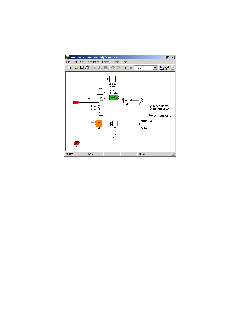
University of Texas at Austin (UT-CEM). The model block representing the FIM of a typical
PA is shown in figure 1. Because version 6 of MATLAB does not permit modeling a pre-
charged capacitor, the capacitor model is charged dynamically at the beginning of the simulation.
In practice, the FIM capacitor is typically pre-charged for the first shot (before or during rotor
motoring) and charged dynamically by the field winding for burst operation.
Referring to the circuit shown in figure 1, there is a current-limiting resistor (0.14
Ω) in
series with a 7 kV voltage source. The value of the dc voltage source was varied to provide in
this case 4.5 kV across the terminals of the field winding at FIM initiation (covered in detail in a
later section of this paper). An ideal SCR switch was gated at the start of the simulation to
charge the capacitor. Also, there will typically be a series impedance between the seed capacitor
EML 205 / CEM 413 Distribution authorized to U.S. Government Agencies and their contractors only
3
and the field winding. As discussed in this paper, the design of this impedance can be tailored
specifically to best suit the requirements of the system.
Figure 1. FIM block as it resides within Simulink
®
IMPACT ON SYSTEM EFFICIENCY
In order to expedite the study, a first order approximation for the charging current profile
was utilized. The field winding self-excitation process follows the exponential profile
approximated by [5];
( )
0
t
i t
I e
α
=
(1)
where
0
initial dc seed current starting point
time
= charging coefficient
α
=
=
I
t
The charging coefficient is a constant that depends on the magnetic coupling between the
field and armature windings, the dc field impedance values, and rotor speed. The calculated
EML 205 / CEM 413 Distribution authorized to U.S. Government Agencies and their contractors only
4
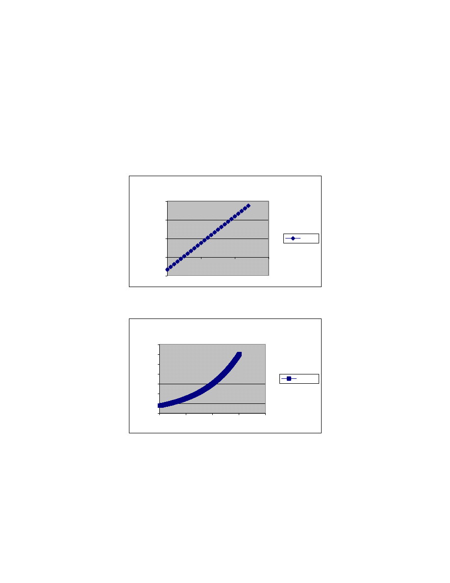
value for the charging coefficient for the study PA is plotted in figure 2. Changing the calculated
values to those produced in simulation resulted in the estimated current profile shown in figure 3.
The seed current value is 15 kA. This curve was compared to results from the Simulink
simulation and proved a close match to those results. Finally, the ohmic losses from this profile
were obtained by squaring and integrating the current profile times the field resistance. These
results are shown in figure 4.
alpha
-5.00E+01
0.00E+00
5.00E+01
1.00E+02
1.50E+02
0
5000
10000
15000
alpha
Figure 2. Charging coefficient vs. rpm for the study PA
current
0
20000
40000
60000
80000
100000
120000
140000
0
0.005
0.01
0.015
0.02
current
Figure 3. Charging current profile vs. time estimation
EML 205 / CEM 413 Distribution authorized to U.S. Government Agencies and their contractors only
5
losses (J)
0
50000
100000
150000
200000
250000
300000
350000
0
0.005
0.01
0.015
0.02
0.025
losses (J)
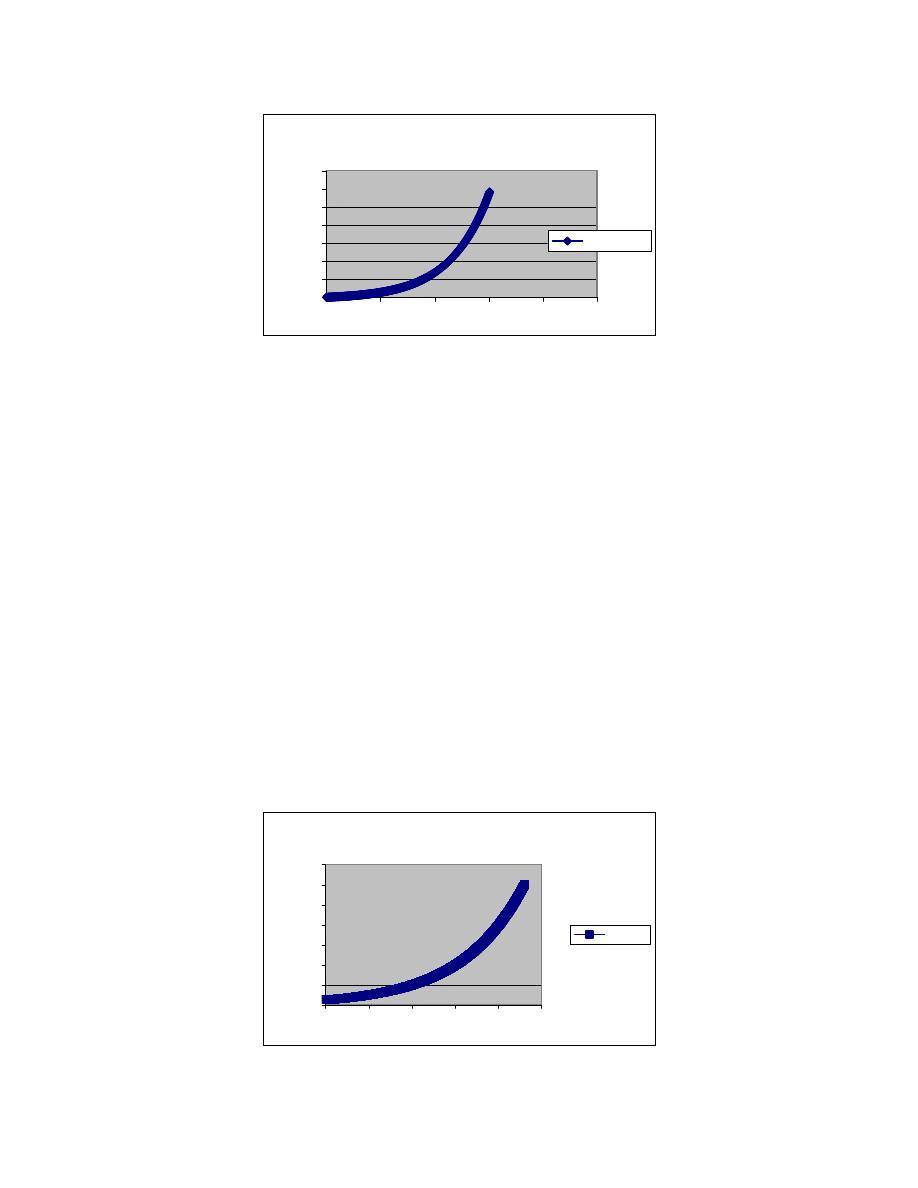
Figure 4. Calculated charging losses vs. time for the study PA field coil
The calculated charging losses detailed above are roughly 300 kJ for the study PA. Simulated
results indicated a value within 0.5% of the calculated losses. Meanwhile, the simulation
predicted a total of 1.13 MJ of total field energy losses, so that the charging cycle accounts for
about 25% of the total field losses.
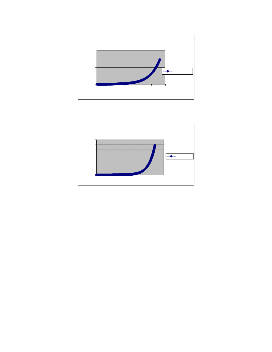
The seed current was reduced to 5 kA, and figures 5 and 6 show the results. Although the
charging time increased from 16 ms to 23 ms, the losses remained about the same. This is borne
out by the strong exponential in the cycle.
As figure 7 shows, at 1 kA seed current, the losses are
still about 300 kJ. What is happening is that the time to achieve the desired field is very much
extended. Ultimately, this could result in an undesirable feel for the gunner, and an undesirable
increase in brush drag, heating, and wear. The results from this are clear: the field efficiency is
not influenced strongly by the seed current.
current
0
20000
40000
60000
80000
100000
120000
140000
0
0.005
0.01
0.015
0.02
0.025
current
Figure 5. Charging current profile vs. time for 5 kA seed current
EML 205 / CEM 413 Distribution authorized to U.S. Government Agencies and their contractors only
6
losses (J)
0
100000
200000
300000
400000
0
0.005
0.01
0.015
0.02
0.025
losses (J)
Figure 6. Charging losses vs. time for 5 kA seed current
losses (J)
0
50000
100000
150000
200000
250000
300000
350000
0
0.01
0.02
0.03
0.04
losses (J)
Figure 7. Charging losses vs. time for 1 kA seed current
SEED CURRENT AND ROTOR SPEED (VOLTAGE) ISSUES
Rotor speed is another important aspect in selecting the proper seed current level. Once
again the main purpose of the FIM is to provide a seed current to the field winding so that the PA
can begin the self-excitation process. And as discussed above, it is a strong function of rotor
speed. In general, the PA can provide power to launch other lower-velocity rounds from
diminished speeds. In addition, for subsystem commissioning and maintenance mode purposes,
UT-CEM engineers routinely operate the PA at a much reduced speed. Based upon these
factors, a minimum operating speed of approximately 50% of the PA design full speed is
recommended.
The next issue is the minimum voltage required from the PA to initiate excitation. This
depends somewhat on the bus line impedances and field coil converter (FCC) characteristics.
EML 205 / CEM 413 Distribution authorized to U.S. Government Agencies and their contractors only
7
Again, experience with these systems has led UT-CEM engineers to conclude that there should
be at least 25 V across each thyristor in the FCC to commence the self-excitation. Voltages less
than 25 V, when combined with particular gate impulses, have resulted in faulty turn-on of SCRs
during testing.
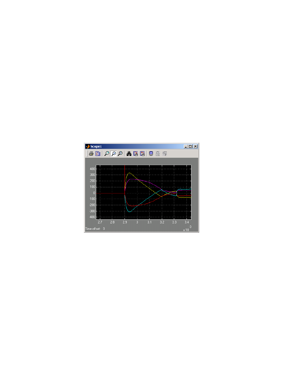
According to figure 2, at 6,000 rpm the study PA still has a strong positive charging
coefficient of 54. To study the effectiveness of this, a 200
µF capacitor charged to 5 kV was
used in the simulation. The resulting voltage profile and start of rectification is shown in figures
8 and 9. Note that the rectification was timed to occur very near the peak seed current location;
otherwise, this should be a valid seed current design point.
Figure 8. Voltage vs. time from 200
µ
F cap @ 5kV discharging into study PA at 6,000 rpm
EML 205 / CEM 413 Distribution authorized to U.S. Government Agencies and their contractors only
8
Figure 9. Field current vs. time from 299
µ
F FIM event of figure 8
SELF EXCITATION AND CONTROL SCHEME
In the simulation results, the FIM discharge was set so that the PA had a switch trigger
that occurred near the peak of the seed current cycle. This meant that for such a low seed current
impulse, the controller would have to consider the speed of the machine and the time of the FIM
discharge event, so that a phase trigger signal coincided at or just after the peak of the seed
current profile. While this is certainly possible, it does add a level of complexity into the
controller design and software.
In previous PA systems, the start of the self-excitation process was passive, i.e., the seed
current pulse was of long enough duration so that a phase trigger always occurred at or just after
peak current was observed. At 6,000 rpm, a phase is available to be triggered every 1.25 ms.
For reliable triggering, a random phase of the seed current impulse must last for more that 2.5
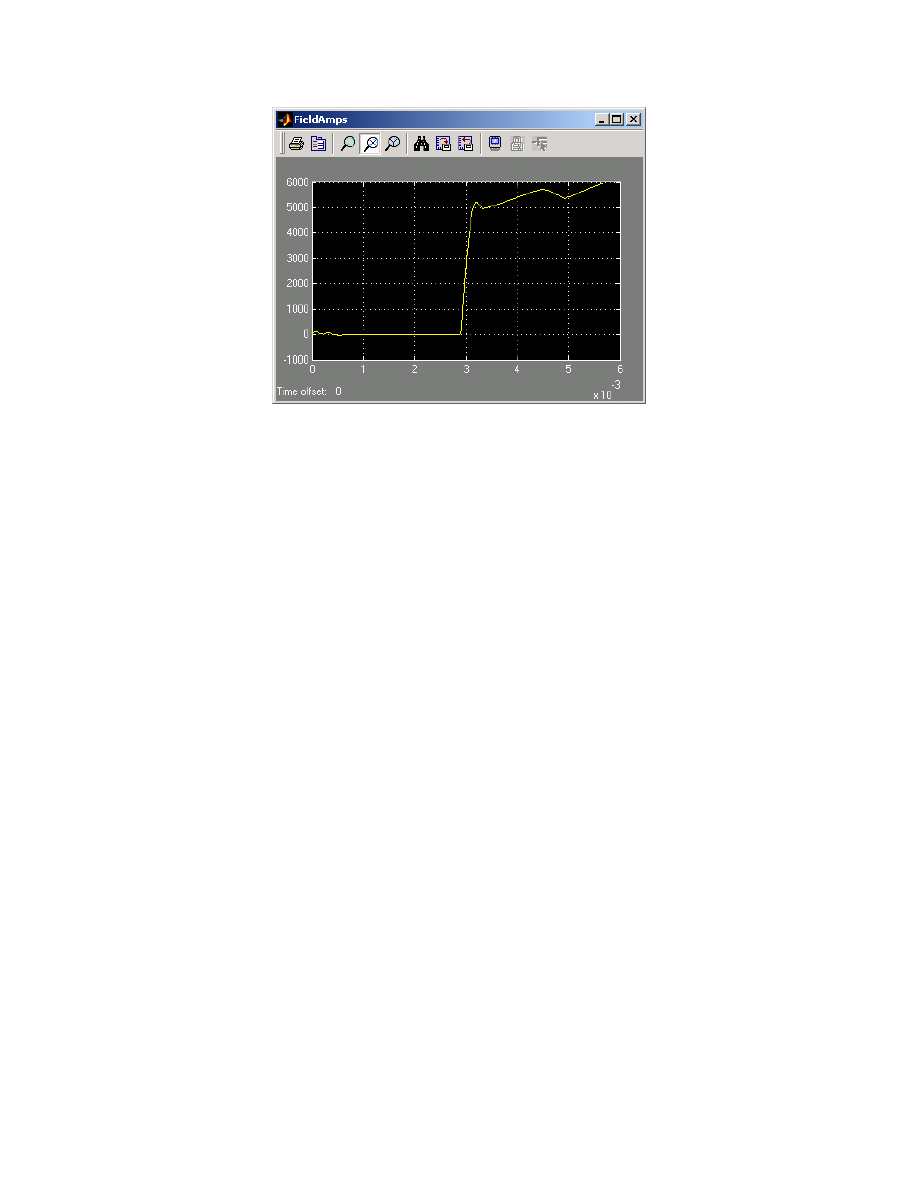
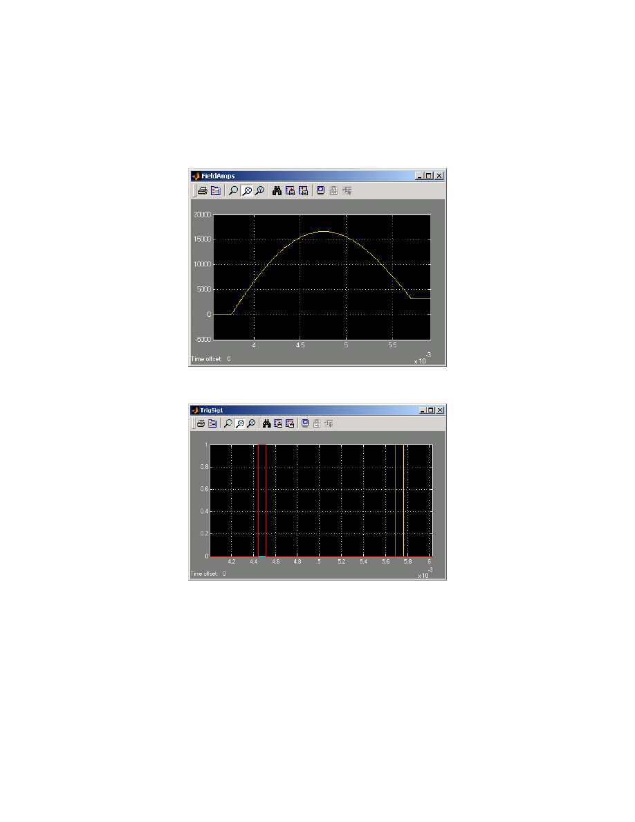
ms. For the simulation that produced figures 10 and 11, the capacitance was set at 2,500
µF at 5
kV charge. The phase 4 trigger sequence occurs just before peak current and phase 1 is then able
to initiate the boot-strapping sequence at the 3 kA field current level. As stated above, this value
is at the bottom range of the desired starting voltage.
It should also be mentioned that the circuit parameters of the FIM itself can be adjusted to
optimize the pulse width and current delivered to the field coil, in order to minimize the
EML 205 / CEM 413 Distribution authorized to U.S. Government Agencies and their contractors only
9
capacitance required. There are additional trade-offs to be considered if FIM adjustment is to be
implemented; however, if a very low capacitance is required (approaching 10% of the value
defined earlier),
a control modification would definitely be warranted.
Figure 10. Seed current for 2,500
µ
F and 5 kV
Figure 11. Phase 4 and 1 FCC trigger points
From the results of this simulation, it can be concluded that there is a strong dependence
on the size of the FIM with the control scheme selected. Minimizing seed capacitance would
seem to necessitate adapting a smart control algorithm to time the phase sequencing with the
FIM discharge.
EML 205 / CEM 413 Distribution authorized to U.S. Government Agencies and their contractors only
10
FIM CHARGE VOLTAGE LEVELS
UT-CEM engineers recommend a charge voltage commensurate with the maximum
charge voltage of the field winding. Capacitor-stored energy is a strong function of voltage, but
there is also an inherent operational fault protection advantage to be gained by using this voltage
level.
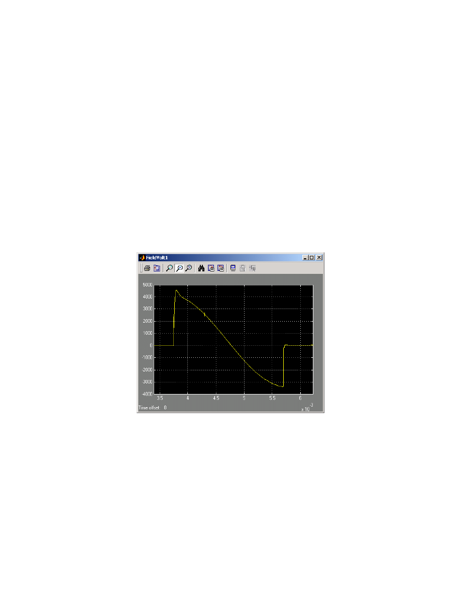
When the properly designed FIM is discharged into the field winding, the capacitor
voltage is seen instantly across the field winding. If there is a brush or insulation issue at this
stage, the fault can be detected early and the discharge terminated with minimal risk to the
generator and its subcomponents. The voltage seen across the field winding for the case of 2,500
µF FIM discharge is shown in figure 12.
Figure 12. Field Volts during 2,500
µ
F, 5kV FIM discharge
SIMULATION VERIFICATION
The
200
µF FIM case was loaded into the performance simulation for the study PA to
make sure the assumptions proved to be adequate. Figure 13 shows the difference between field
charging characteristics in the two cases (2,500 and 200
µF). The results verify that lower seed
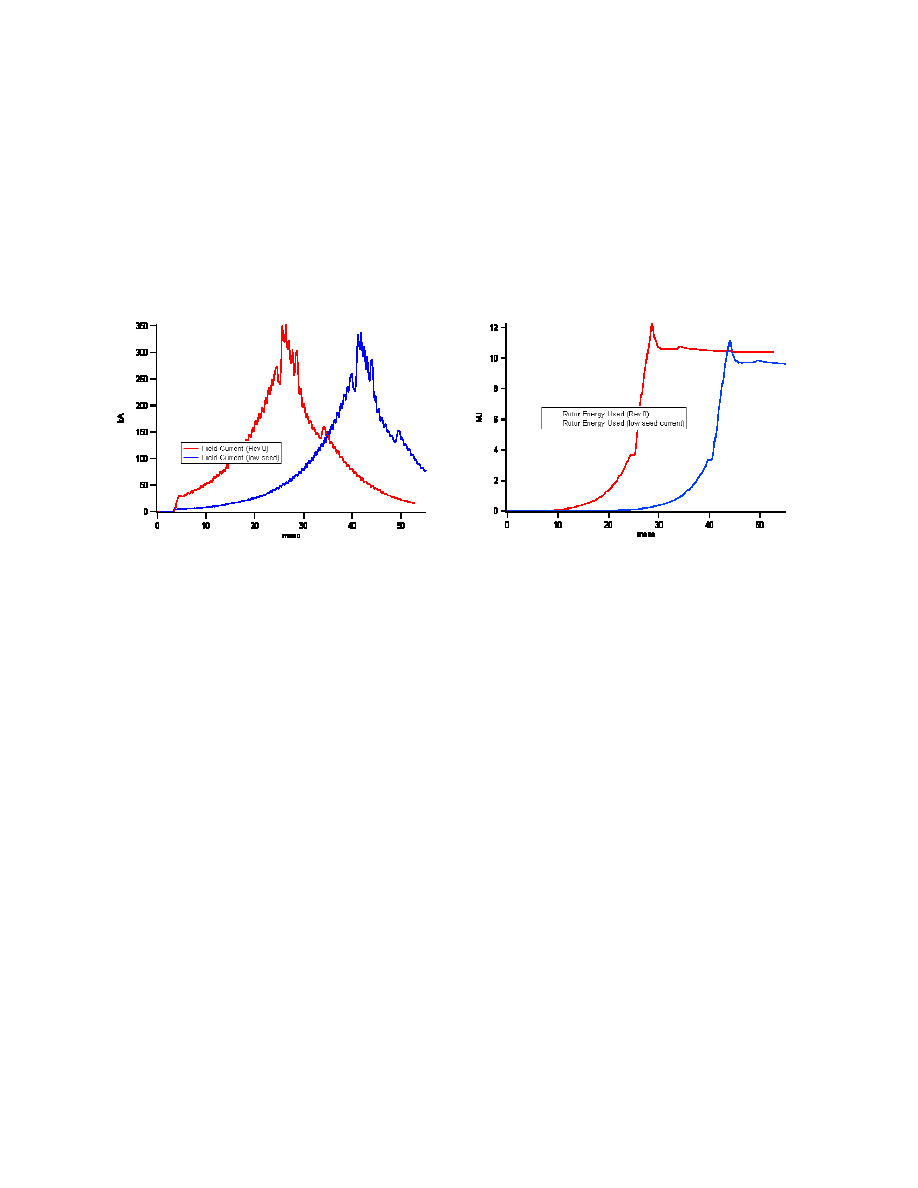
current will result in longer charging durations for the field winding. Figure 14 compares the
EML 205 / CEM 413 Distribution authorized to U.S. Government Agencies and their contractors only
11
two rotor energies extracted during discharge and demonstrates that there is little net difference
produced by using the lower seed current. In fact, the lower seed current case shows slightly less
net energy used because the initial shot phasing was slightly different, based on different seed
starting points. Time did not permit correcting this descrepancy for the purpose of the study, and
it was felt that identifying the general trend was more important.
Figure 13. Current comparisons from simulation
for 4,500
µ
F and 200
µ
F seed capacitors
Figure 14. Rotor energy comparison for
4,500
µ
F and 200
µ
F seed capacitors
CONCLUSIONS AND RECOMMENDATIONS
This paper addressed the general design guidelines of the FIM for any generic PA design.
The guidelines can be summarized as following, and were verified through simulation:
1.
The FIM should be designed so that the PAs can boot-strap from half of the rotor full
design speed.
2.
The FIM should be sized so that a minimum of 25 V appears across all SCRs located in
the FCC.
3.
The FIM seed capacitor size depends heavily on what control scheme is utilized; passive
or calculated (controlled) timed FIM discharge.
Items 2 and 3 are interdependent and must be considered jointly for a successful design.

EML 205 / CEM 413 Distribution authorized to U.S. Government Agencies and their contractors only
12
ACKNOWLEDGEMENT
This research was funded by the U.S. Army and managed by ARDEC, located at
Picatinny Arsenal in New Jersey.
REFERENCES
1.
J.R. Kitzmiller, et al., “Predicted vs. actual performance of a model scale compulsator
system,” IEEE Transactions on Magnetics, vol. 37, no. 1, January 2001, pp. 362-366.
2.
W.F. Weldon, et al., “Fundamental limitations and design considerations for
compensated pulsed alternators,” 2nd IEEE International Pulsed Power Conference,
Lubbock, Texas, U.S.A., June 12-14, 1979.
3.
S.B. Pratap, et al., “Operating modes for compulsator based electromagnetic launcher
systems,” Digest of Technical Papers, 10th IEEE International Pulsed Power Conference,
July 3-6, 1995, vol. 1, pp. 180-185.
4.
J.R. Kitzmiller, S.B. Pratap, and M.D. Driga, “An application guide for compulsators,”
IEEE Transactions on Magnetics, vol. 39, no. 1, January 2003, pp. 285-288.
5.
S.B. Pratap, “Limitations on the minimum charging time for the field coil of air core
compensated pulsed alternators,” IEEE Transactions on Magnetics, vol 27, no. 1, January
1991, pp. 365-368.
Wyszukiwarka
Podobne podstrony:
relacje Eu-Us, Politologia UMCS (2005 - 2010) specjalność samorząd i polityka lokalna, Międzynarodow
[US 2005] 6864611 Synchronous generator for service in wind power plants, as well as a wind power
Hydraulic Gear Pump 1900SRM1136 (05 2005) US EN
Calibrations 8000SRM1134 (05 2005) US EN
relacje Eu-Us, Politologia UMCS (2005 - 2010) specjalność samorząd i polityka lokalna, Międzynarodow
Gasoline Fuel System Mazda 0900SRM1127 (05 2005) US EN
2005 US Army Command & Control of Detainee Ops 20p
us vertigo uav 2005
Gasoline Fuel System GM 0900SRM1126 (05 2005) US EN
us scorpius engine 2005
us fort carlson reg 210 20 2005
us ny slippery slope bugs bioagent exercise 2005
więcej podobnych podstron