Development of the Scorpius
®
LOX/Kerosene Engine Family
Dr. Jeffrey A. Muss
Sierra Engineering Inc.
Dr. Shyama Chakroborty and Dr. Ivett A. Leyva
Microcosm Inc.
Abstract
Microcosm and Sierra Engineering have
been developing a series of low-cost
pressure fed LOX/kerosene engines to
power the Scorpius
®
family of launch
vehicles. This paper focuses on the design,
fabrication and testing of a 20K lb
f
O-F-O
triplet injector with a flight-type ablative
chamber. The test results indicated good
performance and stability. The ablation
rates were higher than desired. Minor
design modifications and additional testing
will complete the engine verification
process.
Introduction
Microcosm has been involved in the
development of low-cost ablative engines
since the inception of the Scorpius
®
program
in 1992.
Low-cost pressure-fed engines
constitute one of the three key technologies
used on the Scorpius
®
family of sub-orbital
and orbital launch vehicles. The other
technologies are all-composite propellant
tanks and High Performance Pressurization
Systems (HPPS). The Scorpius
®
family of
engines are low-cost, simple, pressure-fed
designs of thrust classes ranging from 5K to
320K lb
f
. The engines use LOX and Jet-A
kerosene to power all stages. For example,
the Sprite Mini-lift vehicle, shown in Figure
1, is capable of launching 800 lb
m
to LEO.
Microcosm’s 20K lb
f
engines and its
derivative larger engines are configured in
various launch vehicles within the Scorpius
®
family based on the payload requirements of
the respective launch vehicle. A single
20K lb
f
engine is used on the sub-orbital
SR-M vehicle as well as for the individual
pods of the Sprite booster and sustainer
stages.
Figure 1: Sprite Mini-lift Launch Vehicle.
Larger vehicles use a cluster of these
engines to meet the propulsion requirements.
For example, the Eagle vehicle, capable of
carrying two times the payload of the
baseline Sprite vehicle (~1600 lb
m
to LEO),
is configured with two 20K lb
f
engines in
each of the pods of the first and second
stages.
The Liberty vehicle, with roughly four times
the payload of the Sprite vehicle, would
require four 20K lb
f
engines per pod.
Instead, to minimize the complexity of the
Copyright © 2005 by Microcosm Inc. Published by the Chemical Propulsion Information Agency, with permission
Distribution C: Distribution authorized to US Government Agencies and their Contractors; Critical Technology; October 29 2005.
Other requests for this document shall be referred to DARPA, 3701 N. Fairfax Dr., Arlington, VA 22203-1714.
DESTRUCTION NOTICE - Destroy by any method that will prevent disclosure of contents or reconstruction of the document
2005-0356L
11 pages
system, Microcosm plans to use a single
80K lb
f
thrust engine in each pod of the
Liberty vehicle.
The upper stages of the various launch
vehicles in the Scorpius
®
family require
lower thrust than the booster and 2nd stages.
The upper stage weight also optimizes with
reduced tank pressures (200 psi for the
upper stage versus 550 psi for the booster).
The lower tank pressure mandates reduced
engine chamber pressure. The Eagle launch
vehicle requires an 8K lb
f
thrust class upper
stage engine. Design studies have shown
that the booster engine design can be
operated at the reduced thrust levels with
minor modifications. This not only
minimizes the development cost of the
engine, it keeps the production cost down as
the engine shares many parts with the
booster engine.
Engine Design
The engine technology started with the
design, development, and flight
demonstration of a 5K lb
f
thrust-class engine
(Figure 2). For expendable engines,
ablatively-cooled chambers provide good
performance at greatly reduced cost
compared to regeneratively-cooled chamber
designs. The flight engine utilized a like-on-
like doublet injector and an ablative
chamber, although an F-O-O-F split triplet
was also tested.
Microcosm began working with Sierra
Engineering (Sierra) to develop a low-cost
20K lb
f
injector in late 2002. Scorpius
®
requirements for the 20K lb
f
engine are
listed in Table 1. Sierra traded seven
different injection element concepts on a
variety of criteria including performance,
stability, compatibility, development cost
and recurring cost. The trade ranked an O-
F-O triplet, a like doublet and a pintle as the
top three injector concepts. The O-F-O
triplet injection element is ideally suited for
LOX/hydrocarbon propellant combinations,
where the injected O/F mixture ratio (MR)
for optimal performance is about 2.6.
Figure 2: 5K lb
f
Thrust Chambers.
Table 1: 20K lb
f
Scorpius
®
Launch
Vehicle Engine Requirements
•
P r op e ll an ts
– O x id i z e r
L O X p er M I L-P R F - 2 2 5 0 8 F
– F u e l
J e t- A p e r A S T M D 1 6 5 5 -0 4
•
N o m i n al M ix tu r e R a tio (M R )
2 .4
•
E n g in e i nl et pr es s ur e
( d ow n s tr ea m of va lv e s )
5 0 0 p s ia m ax i m um
•
V a c uu m T h ru st
2 0 ,00 0 lb
f
•
C u m u l ati v e B u rn D ur a tio n
2 0 0 s e co n ds
•
V a c uu m S p ec if ic Im p u ls e ( Is p)
2 8 0 l b
f
-s ec /l b
m
•
N o z z le Ex p an s io n R a ti o
6 .5 6: 1
•
M ax i m um w a ll te m p er at ur e
3 9 0 0 ° R
– C o m p a ti b le w it h S i li c a p h en o li c ch a m b e r li n er
Triplet injectors offer the potential for
higher performance than the doublet
injector, even with the coarse injector
pattern needed to achieve acceptable
stability characteristics.
compatibility can be an issue with O-F-O
triplet injectors. This injector is the baseline
for the current family of Scorpius
®
launch
vehicles.
The injector includes 63 O-F-O triplets, with
equal orifice diameters (0.116 inches).
Canted showerhead fuel film cooling (FFC)
orifices (66) are located around the
periphery. Adjustment of the FFC orifice
size and inclusion of a metering plate permit
the FFC to be varied between 2 and 12%.
The injector layout incorporates a flooded
LOX manifold for enhanced cooling of the
injector face (Figure 3). Detailed transient
thermal-structural of the injector assembly
showed very little plasticity and no
ratcheting. Cyclical Manson strain range is
below 0.0059, with life predicted to exceed
580 cycles with a safety factor of 10.
The injector was designed to reduce
production costs while enhancing reliability.
Interpropellant leak paths were eliminated.
Materials with excellent oxygen
compatibility were selected.
Welds were
reduced to two, with neither contributing to
a CRIT1 failure. Brazes were eliminated.
The component designs were iterated with
machine shops to optimize them for CNC
machining.
Pretest analysis suggested that the engine
would be at least spontaneously stable
without the use of stability aids. Testing
was planned in both a steel hardwall
chamber and a flight-type ablative chamber.
Provisions were made to include a ¼-wave
acoustic cavities if necessary – a cavity
spool was built for the hardwall chamber
and the ablative chamber could be cut to
create the necessary recess.
The ablative combustion chamber is made of
silica phenolic with a graphite-epoxy
filament overwrap. This is a scale-up of the
5K lb
f
chamber fabrication process (Figure
Ignition of the 1
st
stage booster engine will
utilize a ground ignition system, likely a
pyrotechnic or bipropellant torch. However,
the 2
nd
and 3
rd
stages rely on pyrophoric
ignition for high-altitude ignition and restart
capability. The injector incorporates three
ports that can be used for both chamber
pressure measurement and injection of the
pyrophoric ignitier fluid. Initial ground
testing utilized a pyrotechnic ignition
system.
Figure 3: 20K lb
f
Triplet Injector Before
(T) and After (B) Faceplate is Attached
The development of an 80K lb
f
thrust engine
for the Liberty vehicle, derived from the
20K lb
f
triplet engine, was initiated under a
Phase I SBIR from AFRL. Parallel
development is proceeding.
Figure 4: 20K lb
f
Ablative Chambers.
Engine Testing
A 2-week engine test campaign was
conducted in the North test cell of Test
Stand 2A at Edwards AFB during May
2005. Testing was performed using both the
hardwall steel chamber (Figure 5) and three
flight-type ablative chamber (Figure 6).
Two injectors were tested, S/N 001 with
3.8% FFC and S/N 002 with 7.1% FFC.
Figure 5:
20K lb
f
with Hardwall Chamber on
Test Stand 2A at Edwards AFB.
There were twelve successful hot fire tests
(Table 2), out of eighteen attempted tests.
Most failed tests were associated with
facility redline kills. Test chamber pressure
(PC) ranged from 243 to 392 psia and
covered a MR range from 2.18 to 2.36. The
maximum test duration was 30 seconds. Up
to 5 starts were performed on a single
ablative chamber.
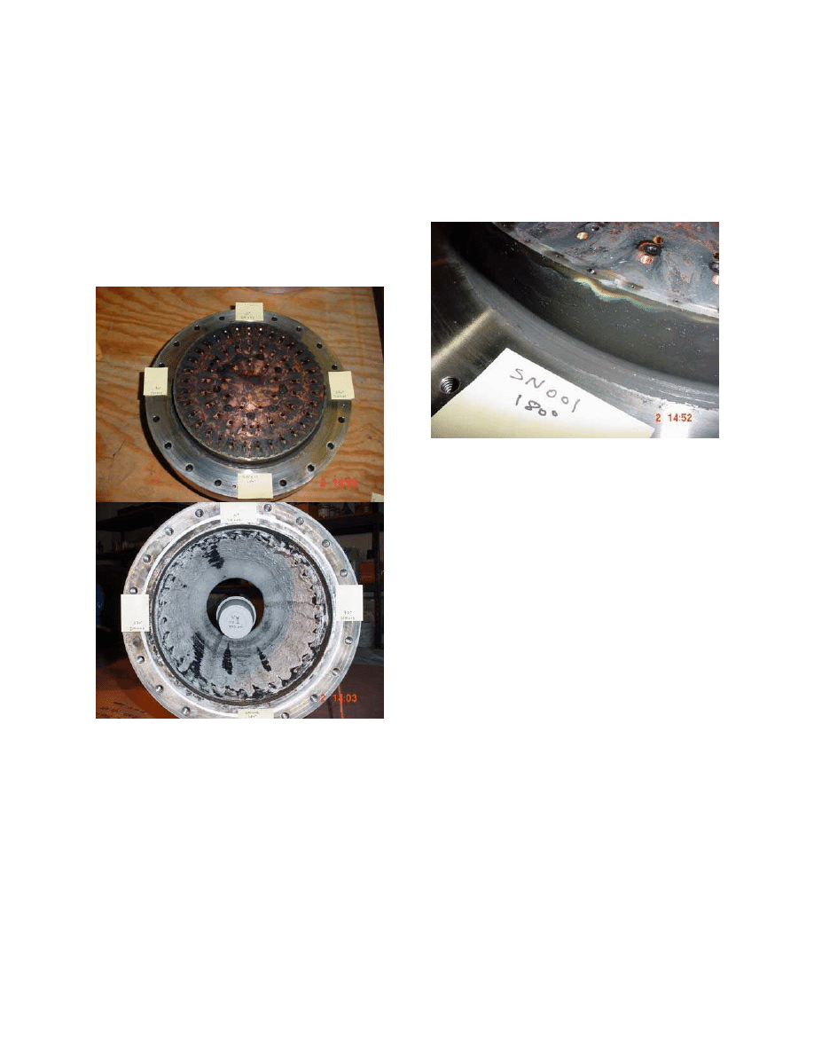
Post-test inspection of the injectors showed
good hardware durability. There was no
damage to the injector face (Figure 7). A
couple small pits were found on the injector
periphery; one was associated with a
remanufactured film cooling injection hole
(Figure 8). Throat erosion appeared to be
uniform (Figure 7).
Characteristic velocity (C*) was the primary
performance metric, as thrust was not
measured during this test series. Redundant
measurements included propellant flowrate
and injector face pressure. Delivered C*
calculations accounted for a throat C
D
and
total pressure loss between the injector face
and throat. The throat area was estimated
from pre- and post-test throat measurements
using conservative assumptions for throat
growth rate. A detailed uncertainty analysis
was performed on the calculated C*;
uncertainty was computed to be
±1.39%
(about 76 ft/s C*). Specific impulse (ISP)
values were estimated from delivered C*
and predicted nozzle efficiency. This
translates into an ISP uncertainty of
±4 lb
f
-s/lb
m
.
Figure 6: 20K lb
f
Engine Firing with
Flight-type Chamber.
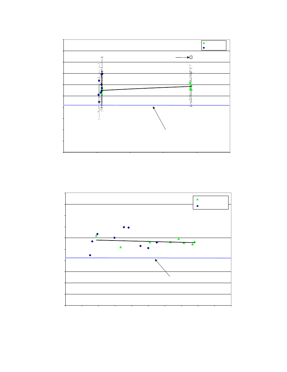
The delivered C* ranged from 5423 to 5547
ft/s during long duration tests. The
estimated vacuum ISP ranged from 281 to
288 lb
f
-s/lb
m
, in all cases exceeding the
required 280 lb
f
-s/lb
m
. There is a weak trend
of increasing engine performance with
increasing chamber pressure (Figure 9 and
Figure 10). The data also shows a weak
downward trend in C* with increasing MR
(Figure 10). There is no clear decrease in
performance as FFC percentage is increased
(Figure 9). Test 19 was very near the
nominal engine operating condition,
producing an average C* of 5387 ft/s
(93.4% efficiency) and a vacuum ISP of 285
lb
f
-s/lb
m
.
Figure 7: Post-test Images of Injector
s/n 001 (T) and Chamber s/n 002 (B).
Dynamic combustion stability was never
demonstrated per CPIA 655.
The injector
was initially tested in a steel hardwall
chamber that did not include acoustic
cavities. During the second bipropellant test
(Test 3), the injector transitioned from rough
combustion (8% peak-to-peak roughness) to
an organized limit-cycle 1T instability (2800
Hz). The instability resulted in only minor
damage to the injector (pitting of the face
bolts). However, errors in the engine
shutdown sequence resulted in damage of
the hardwall chamber, yielding it unusable
on subsequent tests.
Figure 8: Close-up of Pit on Injector Lip
Associated with Remanufactured FFC
Orifice.
Subsequent testing was performed using
ablative chambers. The chamber head-end
was modified to create a ¼-wave acoustic
cavity. The ablative chambers did not
include high-frequency chamber pressure
measurements. However, the injector
instrumentation included triaxial shock
accelerometers. Data from Test 3 showed
good frequency correlation between the
accelerometers and the chamber pressure
measurement, and it permitted the
accelerometer amplitude to be roughly
correlated with chamber pressure
oscillations (Figure 12). Data from Test 17
indicates a steady acceleration of
approximately 70 g peak-to-peak, which
corresponds to about 20 psi peak-to-peak
(about 7.5% of PC). The effectiveness of
the acoustic cavity was also demonstrated.
During the course of Test 17, there were
several large amplitude (about 80 psi or 35%
of PC) “pops” (Figure 13). These pops
damped quickly (approximately 4 msec.),

well below the CPIA 655 requirement damp
time of less than 21 msec.
The chamber ablation rate was slightly
higher than desired for the Scorpius
®
launch
vehicle family booster and sustainer engines.
In particular, there was too much erosion in
the barrel portion of the chamber. The
barrel ablation rate is high in part because
the film cooling injection orifices were not
configured for the inclusion of the acoustic
cavity. The inclusion of the acoustic cavity
forced the FFC to "jump" the cavity inlet
before creating a fuel film along the wall;
the location of the cavity lip should have
been considered when the FFC spray angle
was set. The barrel material density and fuel
film cooling injection features are being
adjusted to enhance compatibility between
the chamber and the triplet injector. This
should minimize the erosion rate. The barrel
wall could also be made thicker to increase
life.
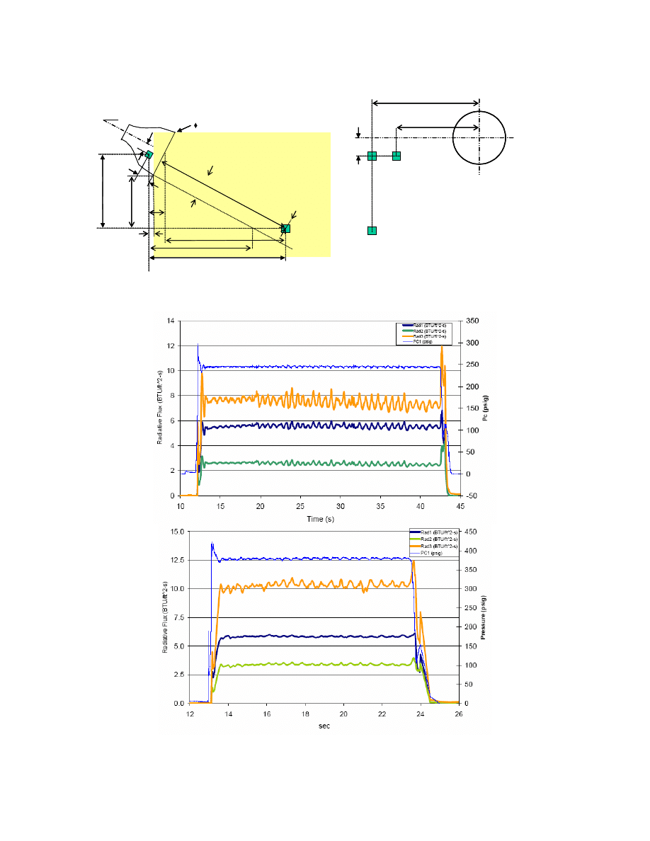
Three narrow field radiometers were
mounted to measure the exhaust plume
emission (Figure 14). Data comparisons
with model plume calculations showed good
agreement. The model plume calculations
are a critical part of the vehicle base heating
analyses.
Summary
The Scorpius
®
family of rocket engines has
achieved a development milestone. A 20K
lb
f
O-F-O triplet injector was tested with
flight-type silica phenolic ablative
chambers. The calculated ISP ranged from
281 to 288 lb
f
-s/lb
m
with an uncertainty of
±4 lb
f
-s/lb
m
. A total of 12 tests were run,
with a maximum run duration of 30 sec. A
1T instability (2800 Hz) occurred early in
the test series with the hardwall chamber.
Nine subsequently tests in an ablative
chamber incorporating a ¼-wave acoustic
cavity showed good stability characteristics.
The ablation rates were slightly higher than
desired. Minor design changes to the
injector and the ablative liners are being
performed to complete the 20K lb
f
engine
development.
References
1
Conger, R.E., Chakroborty, S., Wertz, J.R. and
Kulpa, J.; "The Scorpius Expendable Launch Vehicle
Family and the Status of the Sprite Mini-Lift", 20
th
AIAA International Communications Satellite
Systems Conference (ICSSC), Montreal Canada, 13-
15 May 2002
2
Chakroborty, S., Wertz, J.R. and Conger, R.E.; "The
Scorpius Expendable Launch Vehicle Family and the
Status of the Sprite Small Launch Vehicle", AIAA-
LA Section/SSTC Responsive Space Conference,
2003
3
Muss, J.A., “Advances in the Understanding of
Combustion Characteristics of LOX/Hydrocarbon
Rocket Engines”, Liquid Propellant Rocket
Combustion Instability, V. Yang and W. Anderson
Ed., AIAA Progress in Aeronautics and Astronautics
V 169, 1995
4
Safe Use of Oxygen and Oxygen Systems, H.D
Beeson, W.F. Stewart and S.S. Woods Editors,
ASTM Manual 36, 2000
5
Guidelines for Combustion Stability Specification
and Validation Procedures for Liquid Rocket
Engines, CPIA Publication 655, Jan 1997

Table 2: Summary of Test Data
Test Number
Injector
Chamber
PC (psia)
O/F MR
Steady-State
Duration (s)
C* (ft/s)
η
C* (%)
Estimated ISP
(lbf-s/lbm)
001
S/N 002
Hardwall
-
?
-
002C
S/N 002
Hardwall
235.5
2.772
0.2
003
S/N 002
Hardwall
243.1
2.310
1.8
5479
93.3%
285
010A
S/N 002
Ablative #1
265.7
2.626
0.7
5737
98.8%
301
011
S/N 002
Ablative #1
257.2
2.182
2.2
5472
93.1%
283
012
S/N 002
Ablative #1
257.7-258.3
2.23-2.27
5.2
5484
93.3%
284
5547
94.4%
288
013
S/N 002
Ablative #1
255.9-257.2
2.26-2.29
10.2
5464-5546
93.0-94.4%
284-288
014
S/N 002
Ablative #1
252.6-53.4
2.23-2.24
10
5432-5517
92.2-93.8%
281-286
016
S/N 001
Ablative #3
257.6
2.266
1
5459
92.9%
283
017
S/N 001
Ablative #3
257.2-258.0
2.33-2.26
30
5472-5482
93.3-93.4%
285-286
018A
S/N 001
Ablative #2
390.2
2.237
1
5510
93.7%
286
019
S/N 001
Ablative #2
390.6-392.4
2.30-2.34
10
5487-5497
93.3-93.6%
2845-286
5200
5250
5300
5350
5400
5450
5500
5550
5600
5650
5700
200
250
300
350
400
450
Pc (psia)
C*
(ft/s
)
S/N 001 (3.8%)
S/N 002 (7.1%)
Pretest
Prediction
280 ISP "Requirement"
Figure 9:
Trends of C* with Chamber Pressure and FFC Percentage, Uncertainty Included
5200
5250
5300
5350
5400
5450
5500
5550
5600
5650
5700
2.20
2.22
2.24
2.26
2.28
2.30
2.32
2.34
2.36
2.38
2.40
MR
C*
(ft/s
)
S/N 001 (3.8% FFC)
S/N 002 (7.1% FFC)
280 ISP "Requirement"
Figure 10: Trends of C* with Mixture Ratio and FFC Percentage
270
275
280
285
290
295
200
250
300
350
400
450
Pc (psia)
Es
tima
te
d
Va
c
u
u
m
ISP (lb
f-s
/lb
m)
S/N 001 (3.8% FFC)
S/N 002 (7.1% FFC)
Requirement
Pretest
Prediction
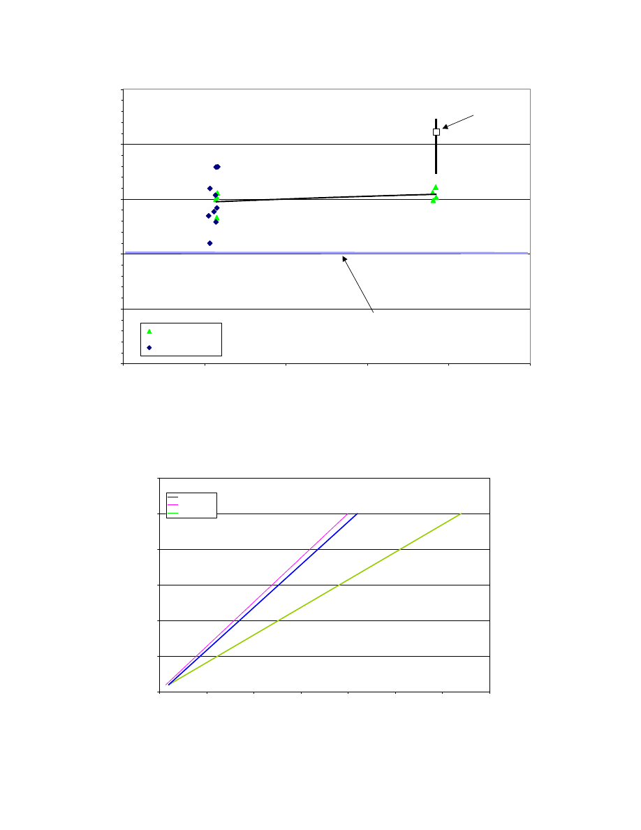
Figure 11:
Trends of Delivered ISP with Chamber Pressure and FFC Percentage
Pretest ISP Prediction with Dispersions and Requirement value (280 lb
f
-s/lb
m
) included for reference.
y = 0.1548x + 4.5161
y = 0.240x - 4.000
0
100
200
300
400
500
600
0
500
1000
1500
2000
2500
3000
3500
G's
psi
AccX (g's p-p)
AccY (g's p-p)
AccZ (g's p-p)
Figure 12: Amplitude Correlation of Vibration Level to Chamber Pressure
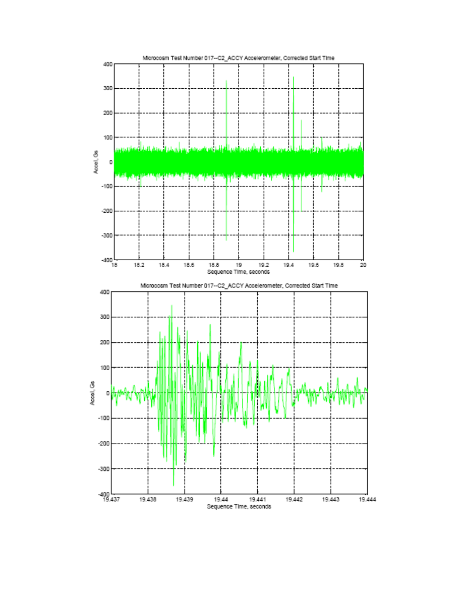
Figure 13: Test 17 Y-Accelerometer Output Showing Mean output (T) and Pop Detail (B).
Front View
looking up Exit
Rad1
Rad2
4.0”
71.69”
36.4”
32°
Rad2
11.312”
4.0”
φ17.225”
Rad3
Rad3
56.293”
40
.6
2
5
”
11.711”
53.289”
8.6125”
3.999”
65.0”
30
.7
1
0
”
Rad1 is 11.0” behind the nozzle exit
Rad2 is 11.312” behind the nozzle exit
7.147”
65.3
39”
Front View
looking up Exit
Rad1
Rad2
4.0”
71.69”
36.4”
32°
Rad2
11.312”
4.0”
φ17.225”
Rad3
Rad3
56.293”
40
.6
2
5
”
11.711”
53.289”
8.6125”
3.999”
65.0”
30
.7
1
0
”
Rad1 is 11.0” behind the nozzle exit
Rad2 is 11.312” behind the nozzle exit
7.147”
65.3
39”
Figure 14:Radiometer Setup (T) and Data for Tests 17 (M) and 19 (B)
Document Outline
Wyszukiwarka
Podobne podstrony:
relacje Eu-Us, Politologia UMCS (2005 - 2010) specjalność samorząd i polityka lokalna, Międzynarodow
Scorpio Engine Data 2.9, LOTUS 7 (locost)
relacje Eu-Us, Politologia UMCS (2005 - 2010) specjalność samorząd i polityka lokalna, Międzynarodow
us vertigo uav 2005
US Army Engineer course Plumbing VI Clear Waste System Stoppages (2004 edition) EN5115
[US 2005] 6864611 Synchronous generator for service in wind power plants, as well as a wind power
1283890431 Control Engineering 05 2005
Engineering Symbols, Prints and Drawings 01 US DOE
Engineering Symbols, Prints and Drawings 02 US DOE
Hydraulic Gear Pump 1900SRM1136 (05 2005) US EN
Calibrations 8000SRM1134 (05 2005) US EN
US Patent 517,900 Steam Engine
Gasoline Fuel System Mazda 0900SRM1127 (05 2005) US EN
2005 US Army Command & Control of Detainee Ops 20p
więcej podobnych podstron