SIMATIC NET
S7–CPs for PROFIBUS
Manual Part B2
CP 343-5
6GK7 343-5FA01-0XE0
version 2 and higher (firmware version V4.1 and higher)
for SIMATIC S7–300 / C7–300
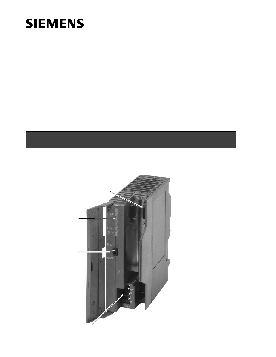
Mode selector
Status and
fault LEDs
Connection for power supply
and functional ground
(9-pin
sub-D female
connector)
CP 343-5

Notes on the Product
B2–2
CP 343-5 for PROFIBUS / Manual Part B2
Release 11/2002
C79000-G8976-C160-02
Notes on the Product
Note
All instructions in the product information bulletin supplied with this product are
valid and must be adhered to.
Compatibility with the Previous Version
Note
Due to the enhanced functionality and restrictions, pay particular attention to
the notes in Chapter 5 of this manual.

B2–3
CP 343-5 for PROFIBUS / Manual Part B2
Release 11/2002
C79000-G8976-C160-02
Contents
PROFIBUS–CPs – General Information
. . . . . . . . . . . . . . . . . . . . . . .
Note
Please remember that Part A of the manual also belongs to the description of the
CPs. Among other things, this includes an explanation of the safety, related
notices and other information that applies to all S7 CPs for Industrial Ethernet.
You can also obtain this general section from the Internet:
http://www4.ad.siemens.de/view/cs/de/8774037
Contents – Part B2
1
Features / Services
. . . . . . . . . . . . . . . . . . . . . . . . . . . . . . . . . . . . . . . . . . . . . . . . . . . . .
2
Installation and Commissioning
. . . . . . . . . . . . . . . . . . . . . . . . . . . . . . . . . . . . . . . . .
3
Displays and Mode Selector
. . . . . . . . . . . . . . . . . . . . . . . . . . . . . . . . . . . . . . . . . . . . .
4
Performance Data
. . . . . . . . . . . . . . . . . . . . . . . . . . . . . . . . . . . . . . . . . . . . . . . . . . . . . .
4.1
Supported Transmission Rates
. . . . . . . . . . . . . . . . . . . . . . . . . . . . . . . . . . . .
4.2
Characteristics of FMS Connections
. . . . . . . . . . . . . . . . . . . . . . . . . . . . . . .
4.3
Characteristics of S5-compatible Communication
(SEND/RECEIVE Interface) on FDL Connections
. . . . . . . . . . . . . . . . . . . .
4.4
Characteristics of S7 Communication
. . . . . . . . . . . . . . . . . . . . . . . . . . . . . .
4.5
Parallel Use of Communication Services (Multiprotocol Mode)
5
Compatibility with the Previous Product
. . . . . . . . . . . . . . . . . . . . . . . . . . . . . . . . .
5.1
Extended functionality Compared with Previous Product
5.2
Replacing Older Modules / Replacing Defective Modules
6
Technical Specifications
. . . . . . . . . . . . . . . . . . . . . . . . . . . . . . . . . . . . . . . . . . . . . . . .

Features / Services
B2–4
CP 343-5 for PROFIBUS / Manual Part B2
Release 11/2002
C79000-G8976-C160-02
Features / Services
Application
The CP 343-5 communications processor is designed for operation in a SIMATIC
S7-300 / C7-300 programmable logic controller. It allows the S7-300 / C7-300 to be
attached to a PROFIBUS fieldbus system.
Services
The current version of the CP 343-5 supports the following communication
services:
S
PROFIBUS–FMS (complying with EN 50170, FMS client and server
functionality)
as FMS master for the following types of connection:
– MMAC: Master–master acyclic
– MSAC: Master–slave acyclic
– MSAC_SI: Master–slave acyclic with slave initiative
– MSCY: Master slave cyclic
– BRCT (broadcast): Sending to all FMS stations
S
S7 communication and PG/OP communication
– PG functions with upload / download of FM modules, configuration /
diagnostics and routing
– operator control and monitoring functions (HMI)
– server for data exchange on one-sided configured connections without
communication blocks in the S7 station
S
S5–compatible communication (SEND/RECEIVE interface) over FDL
connections of the following type:
– specified FDL connections
– Free layer 2 connections (SDA, SDN)
– Broadcast
– Multicast
The CP 343-5 services mentioned above can be used at the same time
independently from one another.
Configuring
STEP 7 from version V5.1 SP3 and higher, and the installation of the NCM for
PROFIBUS optional package, delivered with STEP 7, are necessary for
configuration.
1

Features / Services
B2–5
CP 343-5 for PROFIBUS / Manual Part B2
Release 11/2002
C79000-G8976-C160-02
The module can be configured via the MPI or LAN/PROFIBUS.
Note
If you change the bus parameters in the configuration data, you can only download
these configuration data to the CP via the MPI.
Programming – Using Blocks
”Off–the–peg” blocks (FCs/FBs) form the interface in your STEP 7 user program to
some of the communication services available with the PROFIBUS CP. You will
find a detailed description of these blocks in the NCM S7 for PROFIBUS manuals.
Notice
We recommend that you always use the latest block versions for all module types.
You will find information on the latest block version and links to download the
current blocks in our Customer Support on the Internet:
http://www4.ad.siemens.de/view/cs/en/8797900
If you are using older block types, this recommendation only applies if you also
have the latest firmware version.
You will find further information and Internet addresses in the Preface of the
General Part of this manual.
Replacing a Module without a Programming Device
The CP supports the option of storing the configuration data of the CP in the CPU.
If you use this option, you can replace the module without having to reload the
configuration data from the programming device.
The configuration data are then stored in the load memory of the CPU. The stored
configuration data are protected from power outage by battery backup or by
plugging an EPROM card into the CPU.

Installation and Commissioning
B2–6
CP 343-5 for PROFIBUS / Manual Part B2
Release 11/2002
C79000-G8976-C160-02
Installation and Commissioning
Procedure / Steps
Table 2-1
Step
Comments
1. Install the CP on the S7 standard rail.
2. Establish the connection to the backplane bus
using the enclosed bus connector.
You can use slots 4 to 11 in racks 0 to 3 for the CP
(connected by IM 360/361).
Proceed as explained in the sections on installation
and wiring, described in detail in /1/ .
Note
The CP cannot be used in an expansion rack connected by an IM 365! Reason: The IM 365 does not
connect the required communication bus through to the expansion rack.
3. Connect the CP to the power supply.
To wire up the power supply and CPU, follow the
detailed instructions in /1/.
Notes
S
The CPU, CP and IM (if used) must be connected to the same power supply.
S
Only wire up the S7-300 / C7-300 with the power switched off!
S
When shipped, the CP has a jumper inserted between the M terminals and the functional ground. If
you want to ground the reference potential, do not remove the jumper between the M terminals and
functional ground (see also /1/ particularly the sections on installing an S7-300 with a grounded
reference potential and installing an S7-300 with an ungrounded reference potential).
4. Connect the CP to PROFIBUS.
5. Commissioning is completed by downloading
the configuration data.
For further details, especially regarding node
initialization, please refer to /2/.
2
Displays and Mode Selector
B2–7
CP 343-5 for PROFIBUS / Manual Part B2
Release 11/2002
C79000-G8976-C160-02
Displays and Mode Selector
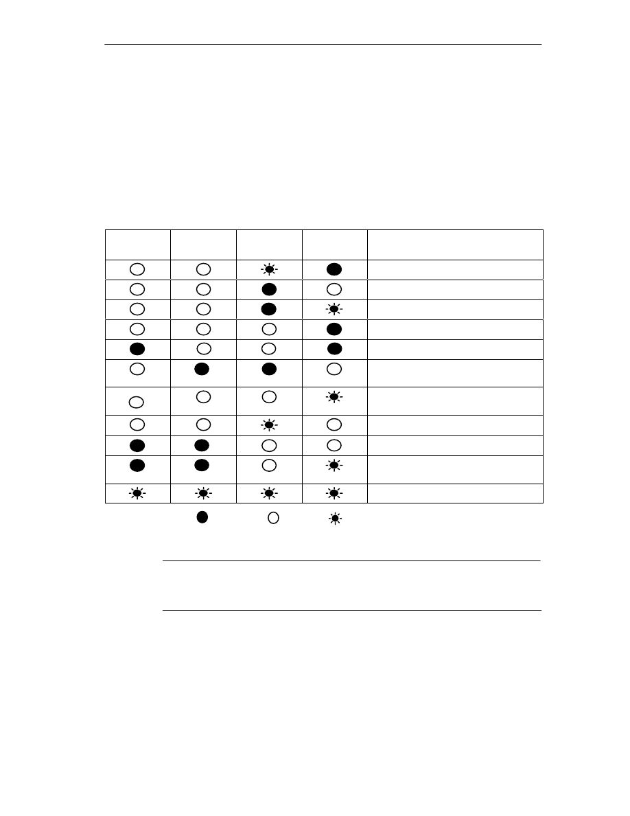
LEDs Displaying the Status of the CP
The different combinations of the four LEDs on the front panel indicate the status
of the CP:
Table 3-1
SF
(red)
BUSF
(red)
RUN
(green)
STOP
(yellow)
CP Operating Mode
Starting up (STOP->RUN)
Running (RUN)
Stopping (RUN->STOP)
Stopped (STOP)
Stopped (STOP)
with errors
Running (RUN) with disturbances on
PROFIBUS
Ready to begin firmware download
(mode active for 10 seconds)
Downloading firmware
Invalid firmware downloaded
Waiting for firmware update (CP
contains incomplete firmware)
Module fault / system error
Key: on off flashing
Note
Read the explanations of the modes of operation in the NCM S7 for PROFIBUS
Manual /2/.
3

Displays and Mode Selector
B2–8
CP 343-5 for PROFIBUS / Manual Part B2
Release 11/2002
C79000-G8976-C160-02
Controlling the Operating Mode
There are different ways in which you can control the mode of the CP 343-5, as
follows:
S
Mode selector
S
NCM S7 for PROFIBUS configuration software
S
SIMATIC Manager in STEP 7
To control the mode from STEP 7 / NCM S7 for PROFIBUS, the mode selector
must be set to RUN.
Mode Selector
With the mode selector, you can set the following modes:
S
Switch from STOP to RUN:
The CP reads the configured and/or modified data into the work memory and
then changes to the RUN mode.
S
Switch from RUN to STOP:
The CP changes to the STOP mode. Established connections (FDL, FMS and
S7 connections) are closed.
In the STOP mode, configuring and performing diagnostics on the CP 343-5 are
possible.
Note
Refer to the information on downloading the database to the CP in the manual /2/.

Performance Data
B2–9
CP 343-5 for PROFIBUS / Manual Part B2
Release 11/2002
C79000-G8976-C160-02
Performance Data
4.1
Supported Transmission Rates
The transmission rate is set with the SIMATIC STEP 7 configuration software. For
permitted values, see Table 6-1 in Section 6.
4.2
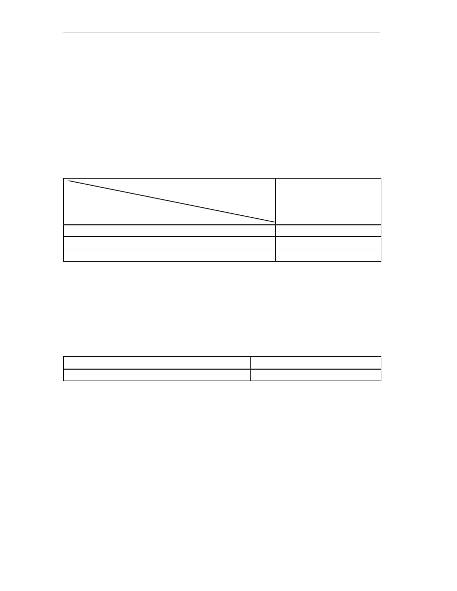
Characteristics of FMS Connections
The following data are important for operating FMS connections:
Table 4-1
Component
Explanation / Values
Number of FMS connections
Maximum of 16
User data length
237 bytes for READ
233 bytes for WRITE and REPORT
Configurable variables
256 server variables and 256 variable descriptions
that can be loaded from the partner. These can be
distributed as required on the maximum number of
configurable FMS connections. The value applies
to elementary data types or arrays of elementary
data types.
This value does not apply to complex data types
(STRUCT)! Note the information in the manual /2/
about using complex data types (STRUCT).
Cycle Load Caused by FMS Connections
When calculating the reaction times with FMS connections, the run time of the
function blocks (FBs) in the S7-300 CPU (314-1 see Table 4-2 ) is the decisive
factor.
The table below shows the cycle load resulting from the available FCs in ms. The
values were obtained using a data length of 230 bytes (array).
Table 4-2
Component /
FB
FB
Number
Job Trigger in ms
(first call)
Job Active in ms
(next call)
Job Complete without
Errors in ms (last call)
IDENT
FB 2
1.8
0.2
5.5
READ
FB 3
2.2
0.2
7.6
4

Performance Data
B2–10
CP 343-5 for PROFIBUS / Manual Part B2
Release 11/2002
C79000-G8976-C160-02
Table 4-2
, Fortsetzung
Component /
FB
Job Complete without
Errors in ms (last call)
Job Active in ms
(next call)
Job Trigger in ms
(first call)
FB
Number
REPORT
FB 4
8.0
0.2
1.8
STATUS
FB 5
1.8
0.2
2.2
WRITE
FB 6
7.6
0.2
2.0
Further Notes on FMS
Please note the following:
In FMS server mode, the CP occupies an unconfigured communication bus
connection on the S7 CPU.
Note that the S7 CPU 314 supports a maximum of 4 (newer CPU types a
maximum of 12) unconfigured K bus connections! If, for example, you operate a
PG and an OP with the S7 CPU, two unconfigured K bus connections are still free.
Note
To allow module replacement without a PG, settings on the CPU must be
modified. Open the Properties dialog of the CPU in HW Config; in the “Monitoring
time for...” box in the “Startup” tab, check and, if necessary, increase the following
values:
– “Transfer of parameters to modules”
Depending on your system (station configuration), you may need to increase the
following parameter:
– “Ready message from modules”

Performance Data
B2–11
CP 343-5 for PROFIBUS / Manual Part B2
Release 11/2002
C79000-G8976-C160-02
4.3
Characteristics of S5-compatible Communication
(SEND/RECEIVE Interface) on FDL Connections
The following information is important for operating FDL connections (specified,
free layer 2 (SDA and SDN), broadcast, multicast):
Table 4-3
Characteristics:
Explanation / Values
Total number of FDL connections that can be
operated
Maximum of 16
Size of the transferable data area on FDL
connections
1–240 bytes maximum per specified FDL
connection (for sending and receiving)
Free layer 2, broadcast and multicast:
1 to 236 bytes of user data can be transferred
per job. The job header requires an additional 4
bytes.
Reaction Times for FDL Connections
The reaction times for FDL connections are largely dependent on the time required
to execute the function blocks (AG-SEND, AG-RECV) on the S7-300 / C7–300
CPU.
Table 4-4
Component
Explanation / Values
Run time on the CPU 314-1
(6ES7 314-1AE04-0AB0)
per AG_SEND block call:
S
6.0 ms with 240 bytes
per block call AG_RECV:
S
7.5 ms with 240 bytes
Performance Data
B2–12
CP 343-5 for PROFIBUS / Manual Part B2
Release 11/2002
C79000-G8976-C160-02
Performance of the FDL Connections
Refer to the following table for transmission rates with FDL connections dependent
on
S
frame length (number of bytes)
S
the type of CPU
The values were measured while sending frames successively (at a transmission
rate of 1.5 Mbps; bus profile standard; 9 nodes).
Table 4-5
Number of FDL Frames per Second
CPU Type /
Transmission rate
Frame length
CPU 314 /
1.5 Mbps
8 bytes
129 / s
128 bytes
130 / s
240 bytes
122 / s
4.4
Characteristics of S7 Communication
The following data are important for operating S7 connections:
Table 4-6
Characteristics:
Explanation / Values
Number of S7 connections
Max.16
1)
1) The actual possible number of S7 connections that can be operated depends on the type of CPU being
used.

Performance Data
B2–13
CP 343-5 for PROFIBUS / Manual Part B2
Release 11/2002
C79000-G8976-C160-02
4.5
Parallel Use of Communication Services (Multiprotocol
Mode)
Performance
Using the various available communication services at the same time affects
communication performance:
S
With a large number of connections (16 FMS connections) and more than eight
S7 connections, FMS performance may drop.
S
With cyclic NCM diagnostics, the update time should be set to 3 seconds,
otherwise communication performance can drop.

Compatibility with the Previous Product
B2–14
CP 343-5 for PROFIBUS / Manual Part B2
Release 11/2002
C79000-G8976-C160-02
Compatibility with the Previous Product
5.1
Extended functionality Compared with Previous Product
The CP 343-5 Basic (6GK7 343-5FA01-0XE0) described here can be used as a
replacement for the previous product CP 343-5 Basic (6GK7 343-5FA00-0XE0).
Extended Functions with 6GK7 343-5FA01-0XE0
The CP 343-5 described here also supports transmission rates > 1.5 Mbps.
5

Compatibility with the Previous Product
B2–15
CP 343-5 for PROFIBUS / Manual Part B2
Release 11/2002
C79000-G8976-C160-02
5.2
Replacing Older Modules / Replacing Defective Modules
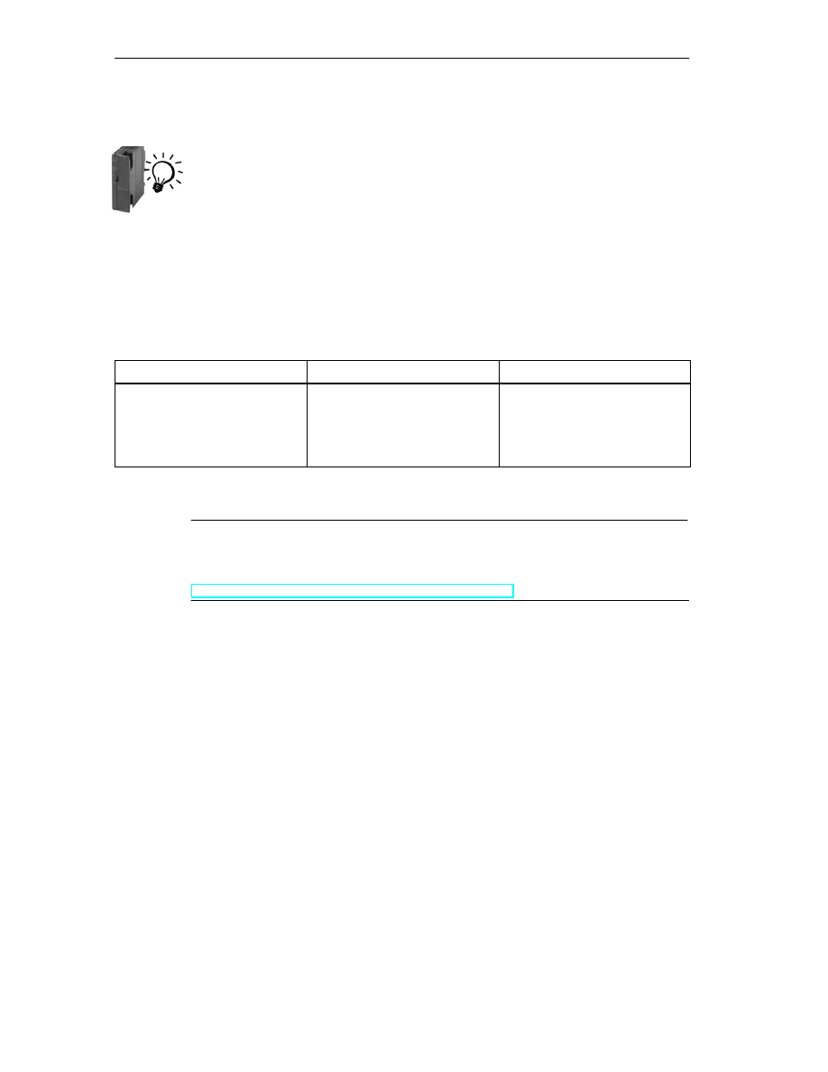
Replacing a Module
Use the following procedure when replacing an older module with one of those
described here:
Table 5-1
Module Used Until Now
Configuration Procedure
6GK7 343-5FA00-0XE0
Configuration unchanged (replacing a defective module)
If you do not require any extended functionality compared with the
functions provided by the old CP (for example transmission rate), no
changes to the configuration are necessary.
During commissioning, simply remember the following distinction:
S
If you selected the option of storing the configuration data of the
old CP on the CPU, this configuration data will be downloaded to
the CP automatically during start up.
S
Otherwise download the configuration data to the CP again from
your PG/PC.
Extending the Configuration (using new functions)
If you want to use the extra possibilities provided by the new CP,
follow the steps below:
1. Replace the previously configured CP 343-5 with the new module
with order number 6GK7 343-5FA01-0XE0 in STEP 7 / HW
Config. You will find the new module in the hardware catalog.
2. Complete your configuration according to your requirements, for
example using the Properties dialog of the PROFIBUS subnet.
3. Use the FBs (V1.5 or higher) shipped with STEP 7 V5.1 or higher
for FMS and regenerate the instance data blocks.
4. Save, compile, and download the configuration data and blocks
to the CPU or CP again.
Note
If you cannot fill the slot left empty after replacing the module by moving the other
modules back one slot, remember to insert a dummy module
(6ES7 370-0AA01-0AA0).
In this case, the address switch on the back of the module must be set to
“Non-Address-Mode” (NA).
Compatibility with the Previous Product
B2–16
CP 343-5 for PROFIBUS / Manual Part B2
Release 11/2002
C79000-G8976-C160-02
Information in the Online Help and the Documentation for NCM S7 for PROFIBUS
The additional information “for newer modules” in both the online help of STEP 7 /
NCM S7 and in the NCM S7 for PROFIBUS manual apply to the CP described
here. Look for the symbol shown here.
Compatibility
The CP 343-5 functions differently compared with the previous module. Make sure
you are aware of the effects in your user program. The following table provides you
with an overview.
Table 5-2
Changed Reaction
Situation
Until Now
Now
Receive buffer for AG_RECV is
too small
If the receive buffer is too small,
data are received up to the buffer
size.
The call is acknowledged with
error message 8185
H
.
If the receive buffer is too small,
no data are received.
The call is acknowledged with
error message 80B1
H
.
Notice
When writing new user programs, you should always use the latest versions of the blocks. You will find
Information on the current block versions and download links for the current blocks on the Internet at:

Technical Specifications
B2–17
CP 343-5 for PROFIBUS / Manual Part B2
Release 11/2002
C79000-G8976-C160-02
Technical Specifications
General Technical Specifications
Table 6-1
Technical Specifications
Value
Supported Transmission Rates
9.6 Kbps, 19.2 Kbps, 45.45 Kbps
93.75 Kbps, 187.5 Kbps, 500 Kbps
1.5 Mbps, 3 Mbps, 6 Mbps, 12 Mbps
Interfaces
Attachment to PROFIBUS
9-pin sub-D female connector
Maximum current consumption on the PROFIBUS
interface with network components attached (for
example, optical network components)
100 mA at 5V
Power supply
24 V DC
Current consumption
- from 24 V:
- from S7-300 / C7-300 backplane bus
0.25 A typical
150 mA typical
Cable cross section for 24V
0.25...2.5 mm
2
Power loss
6 W
S
Permissible ambient temperature according to
/1/, the following temperature ranges must not
be exceeded in S7-300 / C7-300 tiers
- horizontal installation
- vertical installation
S
Transportation/storage temperature
S
Relative humidity max.
S
Altitude
0 to 60
_
C
0 to 40
_
C
–40
°
C to +70
°
C
95% at +25
°
C
up to 2000 m above sea level
Dimensions W x H x D (mm)
40 x 125 x 120
Weight
approx. 300 g
All the information in the Section “General Technical Specifications” in /1/ on the
following topics also applies to the CP 343-5
S
Electromagnetic compatibility
S
Transportation and storage conditions
S
Mechanical and climatic ambient conditions
S
Specifications for insulation tests, protection class, and protection level
6
Document Outline
- S7-CPs Manual / Part B2 Description of the CP 343-5
- Notes on the Product
- Contents
- 1 Features / Services
- 2 Installation and Commissioning
- 3 Displays and Mode Selector
- 4 Performance Data
- 5 Compatibility with the Previous Product
- 6 Technical Specifications
Wyszukiwarka
Podobne podstrony:
S7 300 CP343 2 CP343 2P e
S7 300 CP343 1 Lean e
Podręcznik S7 300
Komunikacja PROFIBUS, S7 200, S7 300(1)
I1 Prototypowanie algorytmów sterowania pracą elastycznej linii w środowisku PLC S7 300
Komunikacja MPI, S7 200, S7 300
S7 300 FM351 e
SIEMENS S7 300
S7 300 w praktyce Część 3 Pierwszy program
Diagnostyka sterownika S7 – 300 Część 1 – wykrywanie błędów systemowych
S7 300 cp340 e
S7 300 SM338 e
mFAQ 3 4 Komunikacja PROFIBUS S7 200 S7 300
mFAQ 3 3 Komunikacja MPI S7 200 S7 300
więcej podobnych podstron