2008 Chevrolet Aveo
|
Aveo, Wave, G3, Barina (VIN S/T) Service Manual
|
Suspension
|
Rear Suspension
|
Specifications
| Document ID: 1294218
Fastener Tightening Specifications
Application
Specification
Metric
English
Rear Axle to Body Bracket Bolt
115 N·m
85 lb ft
Rear Axle Mounting Bracket Bolts
70 N·m
52 lb ft
Rear Hub Caulking Nut
190 N·m
140 lb ft
Shock Absorber-to-Axle Bolt - Lower
72 N·m
53 lb ft
Shock Absorber-to-Body Bolts - Upper
50 N·m
37 lb ft
© 2010 General Motors Corporation. All rights reserved.
Page 1 of 1
Document ID: 1294218
7/6/2010
http://localhost:9001/si/showDoc.do?docSyskey=1294218&pubCellSyskey=56023&pubObj...
2008 Chevrolet Aveo
|
Aveo, Wave, G3, Barina (VIN S/T) Service Manual
|
Suspension
|
Rear Suspension
|
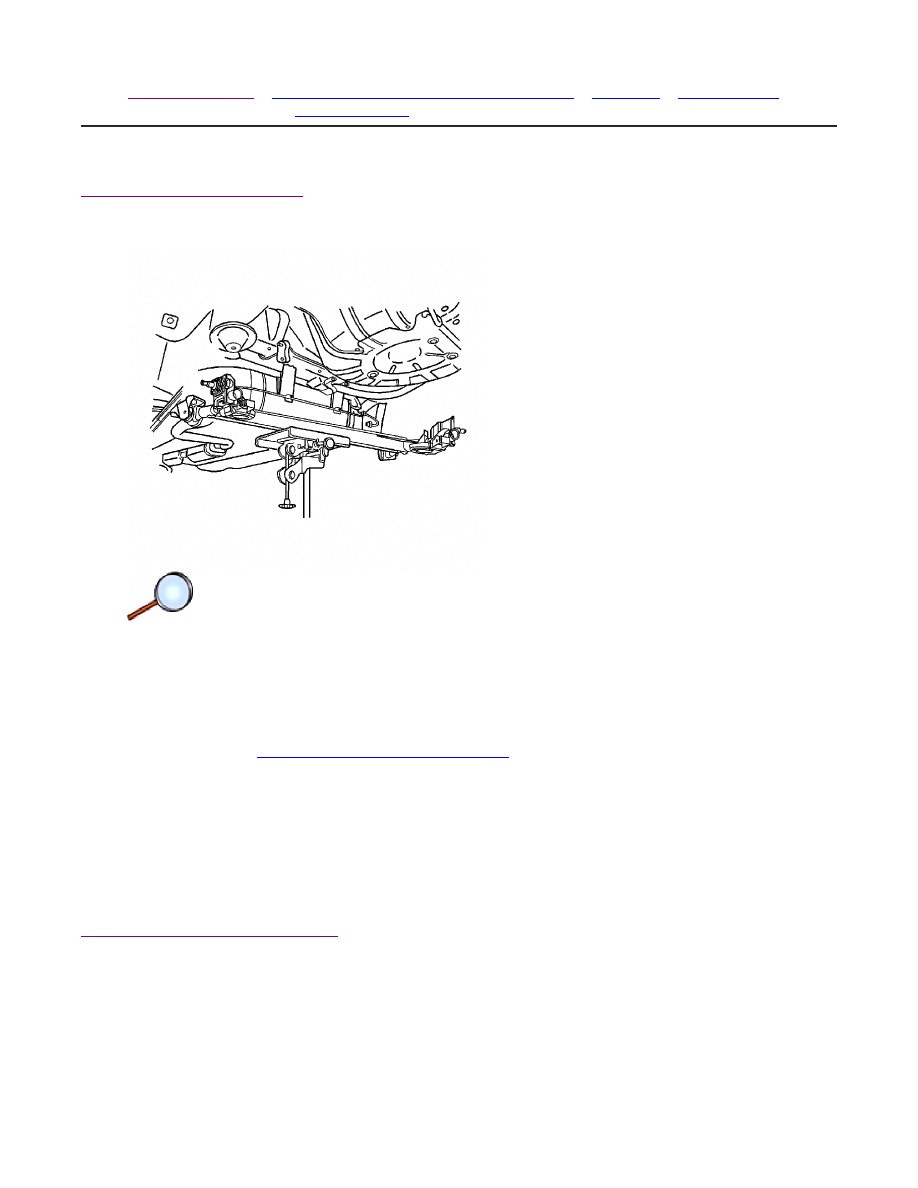
Component Locator
| Document ID: 1755600
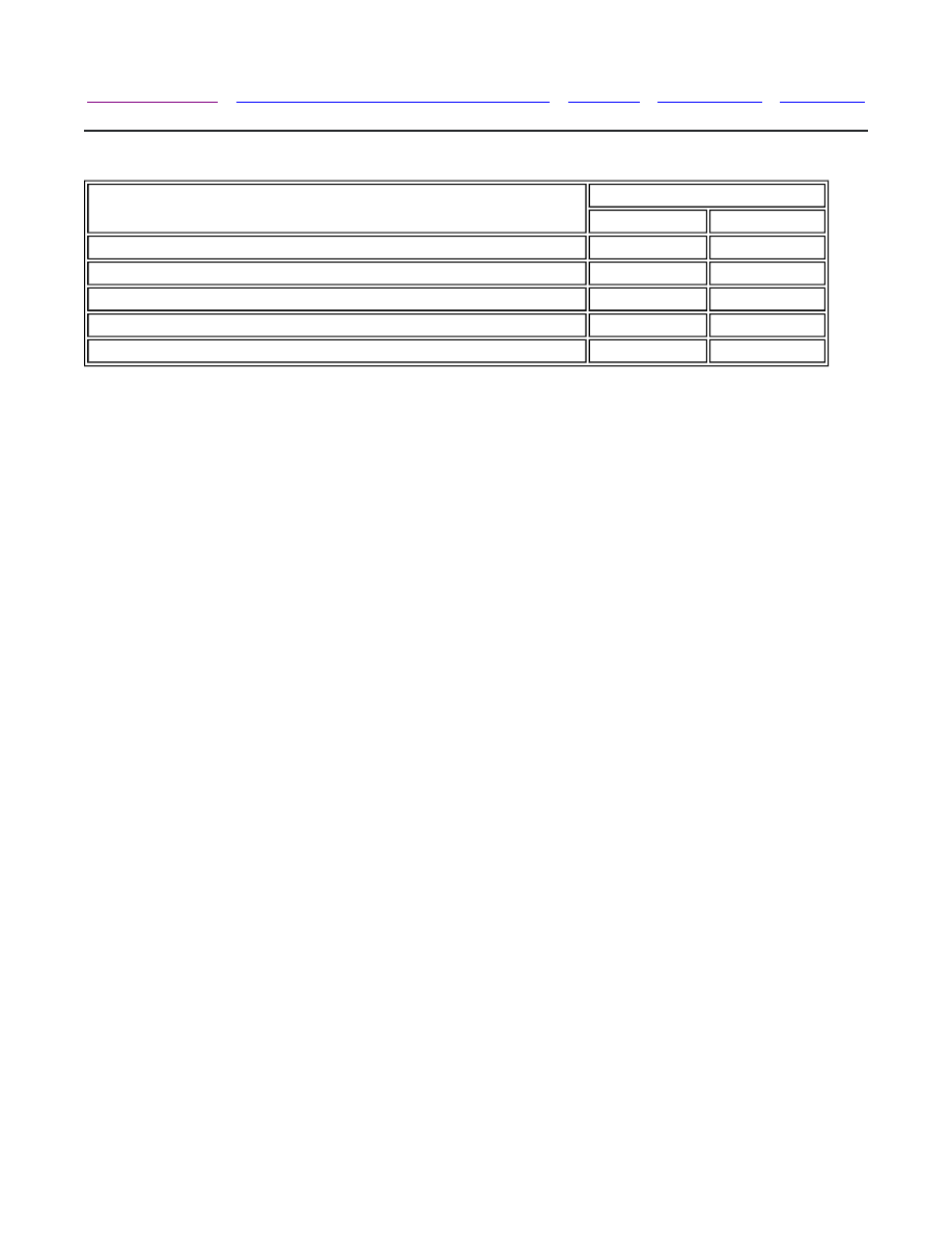
Rear Suspension Components
(1) Shock Absorber Upper Bolt
(2) Spring Upper Insulator
(3) Coil Spring
(4) Spring Lower Insulator
(5) Rear Wheel Bearing and Hub Assembly
(6) Brake Drum
(7) Caulking Nut
(8) Spindle Cap
(9) Spindle
(10) Rear Axle
(11) Shock Absorber Lower Bolt
(12) Shock Absorber
© 2010 General Motors Corporation. All rights reserved.
Page 1 of 1
Document ID: 1755600
7/6/2010
http://localhost:9001/si/showDoc.do?docSyskey=1755600&pubCellSyskey=56032&pubObj...
2008 Chevrolet Aveo
|
Aveo, Wave, G3, Barina (VIN S/T) Service Manual
|
Suspension
|
Rear Suspension
|
Repair Instructions
| Document ID: 1757007
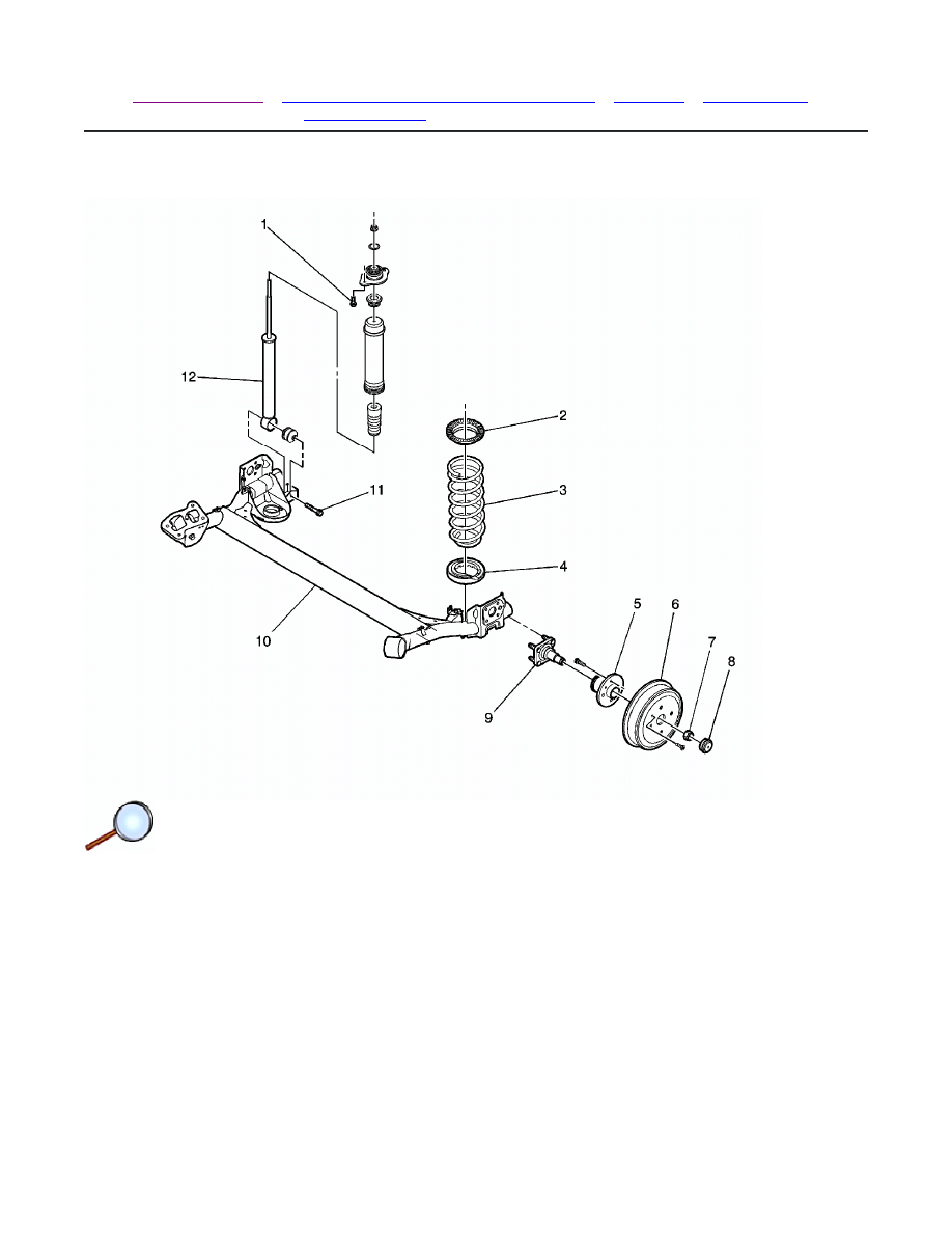
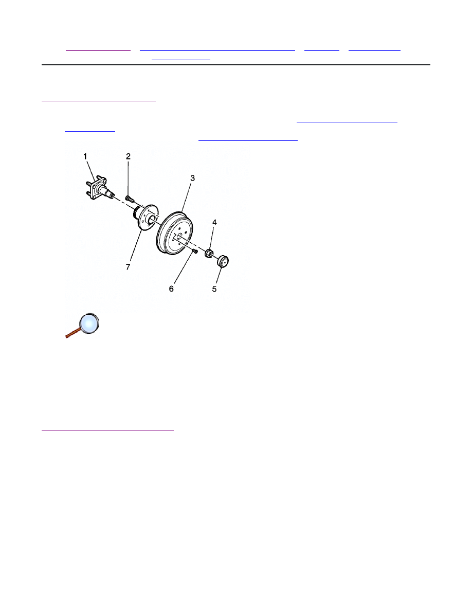
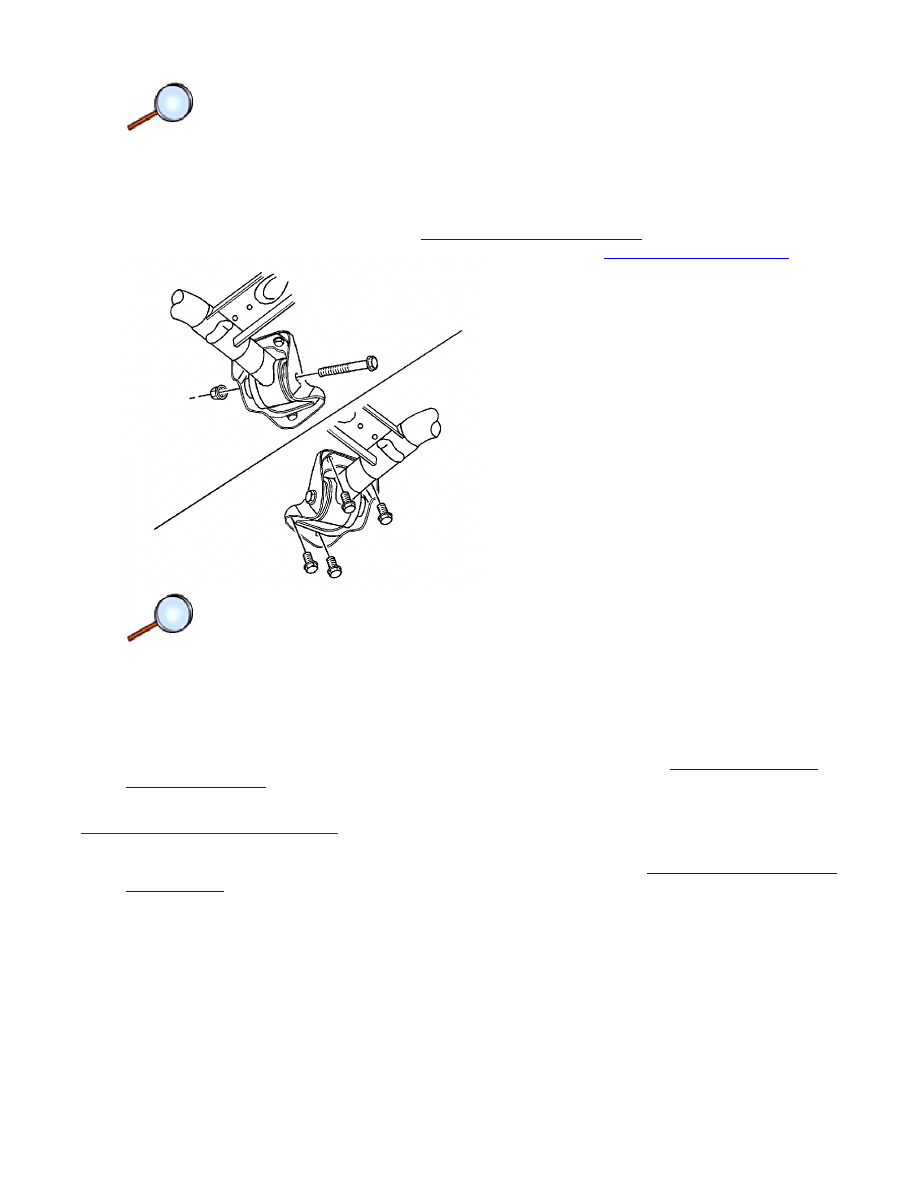
Rear Wheel Bearing and Hub Replacement
Removal Procedure
1. Remove the rear wheel speed sensor, if equipped. Refer to
Rear Wheel Speed Sensor
Replacement
.
2. Remove the brake drum. Refer to
Brake Drum Replacement
.
3. Unstake the caulking nut (4).
4. Remove the caulking nut.
Important: Pull the wheel bearing and hub assembly straight off the spindle. The 2 inner
wheel bearing races may not be secure.
5. Remove the wheel bearing and hub assembly (7) from the spindle (1).
Installation Procedure
© 2010 General Motors Corporation. All rights reserved.
Page 1 of 2
Document ID: 1757007
7/6/2010
http://localhost:9001/si/showDoc.do?docSyskey=1757007&pubCellSyskey=56121&pubObj...
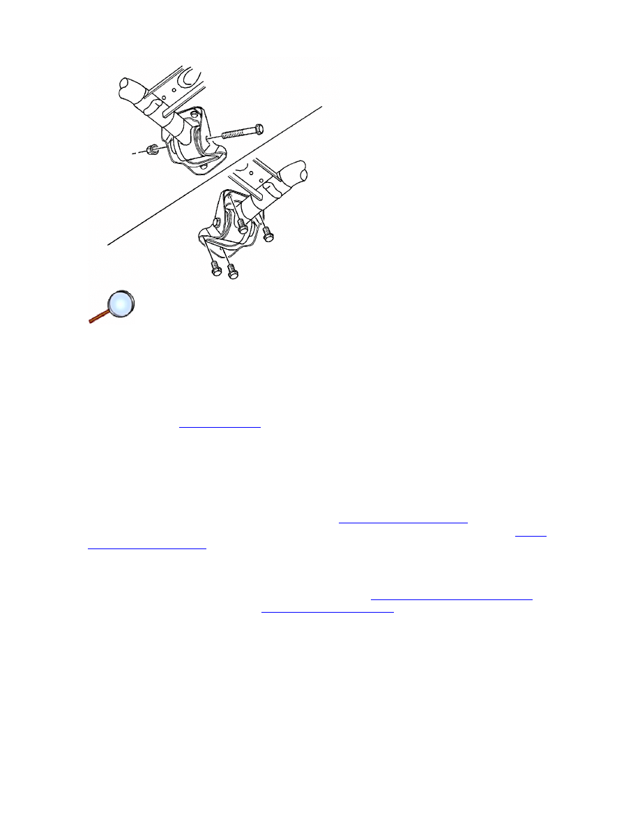
Important: Slide the wheel bearing and hub assembly straight onto the spindle. Use care in
order to properly position the wheel bearing races on the spindle.
1. Install the wheel bearing and hub assembly (7) to the spindle (1).
Notice:
Refer to
Fastener Notice
in the Preface section.
2. Install the caulking nut (4) to the spindle.
Tighten
Tighten the nut to 190 N·m (140 lb ft).
3. Stake the caulking nut.
4. Install the brake drum. Refer to
Brake Drum Replacement
.
5. Install the rear wheel speed sensor, if equipped. Refer to
Rear Wheel Speed Sensor
Replacement
.
Page 2 of 2
Document ID: 1757007
7/6/2010
http://localhost:9001/si/showDoc.do?docSyskey=1757007&pubCellSyskey=56121&pubObj...
2008 Chevrolet Aveo
|
Aveo, Wave, G3, Barina (VIN S/T) Service Manual
|
Suspension
|
Rear Suspension
|
Repair Instructions
| Document ID: 1294227
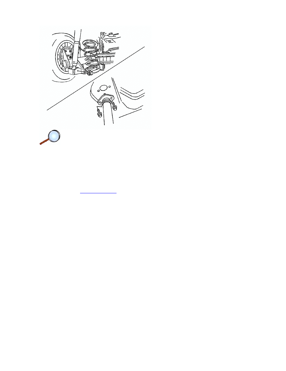
Shock Absorber Replacement
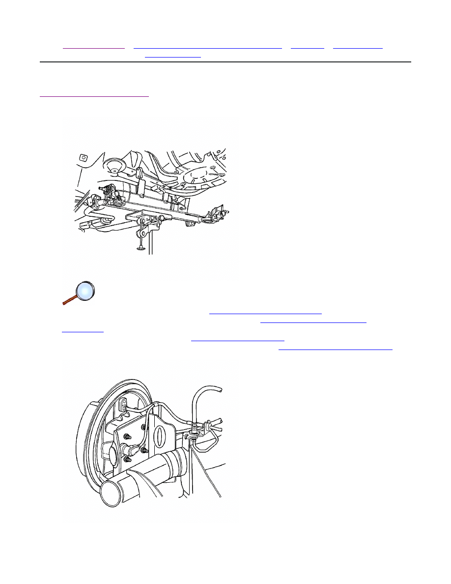
Removal Procedure
Notice: Remove only one shock at a time when both shocks are being replaced. Do not
suspend the rear axle by the brake hoses. Damage to the brake hoses may result.
1. Remove the shock absorber-to-body bolts - upper.
Notice:
Refer to
Vehicle Lifting and Jacking Notice
in the Preface section.
Important: When lifting the vehicle with a body hoist, it will be necessary to support the
rear axle with adjustable jack stands.
2. Raise the vehicle and support the rear axle assembly.
3. Remove the lower shock absorber-to-axle bolt.
4. Remove the shock absorber.
Installation Procedure
© 2010 General Motors Corporation. All rights reserved.
Page 1 of 2
Document ID: 1294227
7/6/2010
http://localhost:9001/si/showDoc.do?docSyskey=1294227&pubCellSyskey=56035&pubObj...
Important: It will be necessary to bring the axle assembly to trim height prior to tightening
the shock absorber attachment bolts.
1. Insert the lower shock absorber-to-axle bolt through the shock absorber lower attachment
bracket and into the axle.
Notice:
Refer to
Fastener Notice
in the Preface section.
2. Lower the vehicle enough to guide the upper shock stud on the body opening and loosely
install the attaching bolts.
Tighten
• Tighten the lower shock absorber-to-axle bolt to 72 N·m (53 lb ft).
• Tighten the upper shock absorber-to-body bolt to 50 N·m (37 lb ft).
Page 2 of 2
Document ID: 1294227
7/6/2010
http://localhost:9001/si/showDoc.do?docSyskey=1294227&pubCellSyskey=56035&pubObj...
2008 Chevrolet Aveo
|
Aveo, Wave, G3, Barina (VIN S/T) Service Manual
|
Suspension
|
Rear Suspension
|
Repair Instructions
| Document ID: 1294237
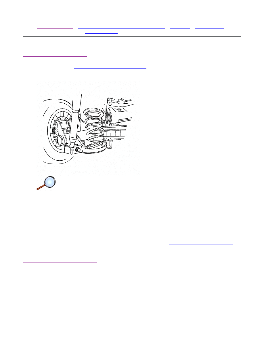
Coil Spring Replacement
Removal Procedure
Notice:
Refer to
Vehicle Lifting and Jacking Notice
in the Preface section.
Caution: When removing the rear springs, do not use a twin-post type hoist. The swing arch
tendency of the rear axle assembly when certain fasteners are removed may cause it to slip
from the hoist which may cause personal injury.
1. Raise and suitably support the vehicle. Use a frame contact hoist if possible and support the
rear control arms with jack stands. If it becomes necessary to lift the vehicle with a twin-post
hoist, lift the body and support the control arms with jack stands.
2. Remove the wheel. Refer to
Tire and Wheel Removal and Installation
.
3. Remove the right and the left shock absorber bolts. Refer to
Shock Absorber Replacement
.
4. Lower the rear axle and remove the springs and the top insulator.
Installation Procedure
© 2010 General Motors Corporation. All rights reserved.
Page 1 of 3
Document ID: 1294237
7/6/2010
http://localhost:9001/si/showDoc.do?docSyskey=1294237&pubCellSyskey=56019&pubObj...
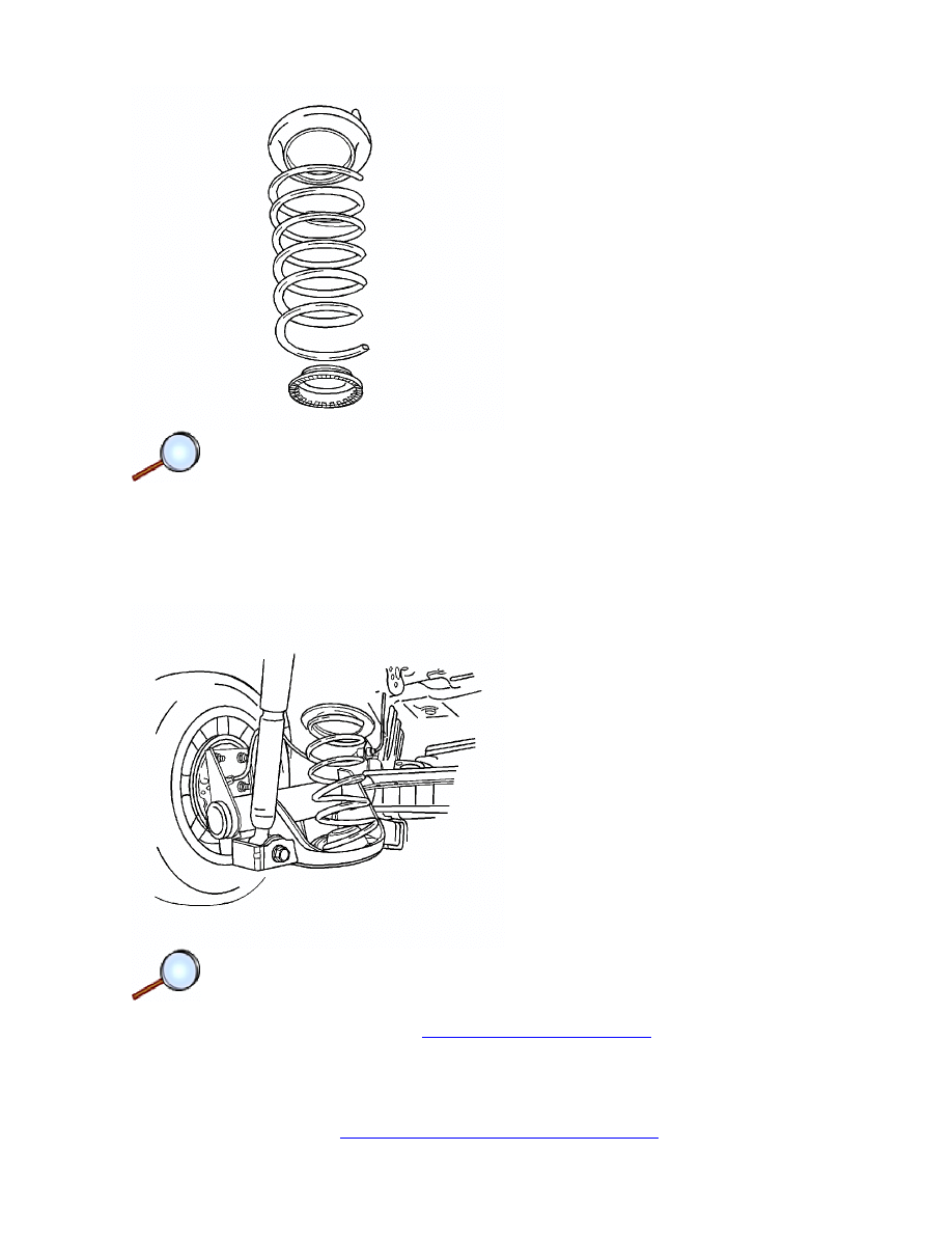
Important: Prior to installing the springs, it will be necessary to install the upper insulators
to the body and adhesive to keep them in position while raising the axle assembly and the
springs.
1. Install the upper insulator and seat the lower bumper.
2. Install the springs and raise the axle.
3. Install the shock absorbers. Refer to
Shock Absorber Replacement
.
Important: It will be necessary to bring the axle assembly to trim height prior to tightening
the shock absorber attachment bolts.
4. Install the wheel. Refer to
Tire and Wheel Removal and Installation
.
Page 2 of 3
Document ID: 1294237
7/6/2010
http://localhost:9001/si/showDoc.do?docSyskey=1294237&pubCellSyskey=56019&pubObj...

5. Remove the jack stands and lower the vehicle.
Page 3 of 3
Document ID: 1294237
7/6/2010
http://localhost:9001/si/showDoc.do?docSyskey=1294237&pubCellSyskey=56019&pubObj...
2008 Chevrolet Aveo
|
Aveo, Wave, G3, Barina (VIN S/T) Service Manual
|
Suspension
|
Rear Suspension
|
Repair Instructions
| Document ID: 1294241
Rear Axle Replacement
Removal Procedure
1. Raise and support the vehicle. Refer to
Lifting and Jacking the Vehicle
.
2. Remove the rear tire and wheel assemblies. Refer to
Tire and Wheel Removal and
Installation
.
3. Remove the brake shoes. Refer to
Brake Shoe Replacement
.
4. Remove the park brake cable from the rear axle. Refer to
Park Brake Cable Replacement
.
5. Disconnect the wheel speed sensor connector, if equipped.
© 2010 General Motors Corporation. All rights reserved.
Page 1 of 4
Document ID: 1294241
7/6/2010
http://localhost:9001/si/showDoc.do?docSyskey=1294241&pubCellSyskey=56031&pubObj...
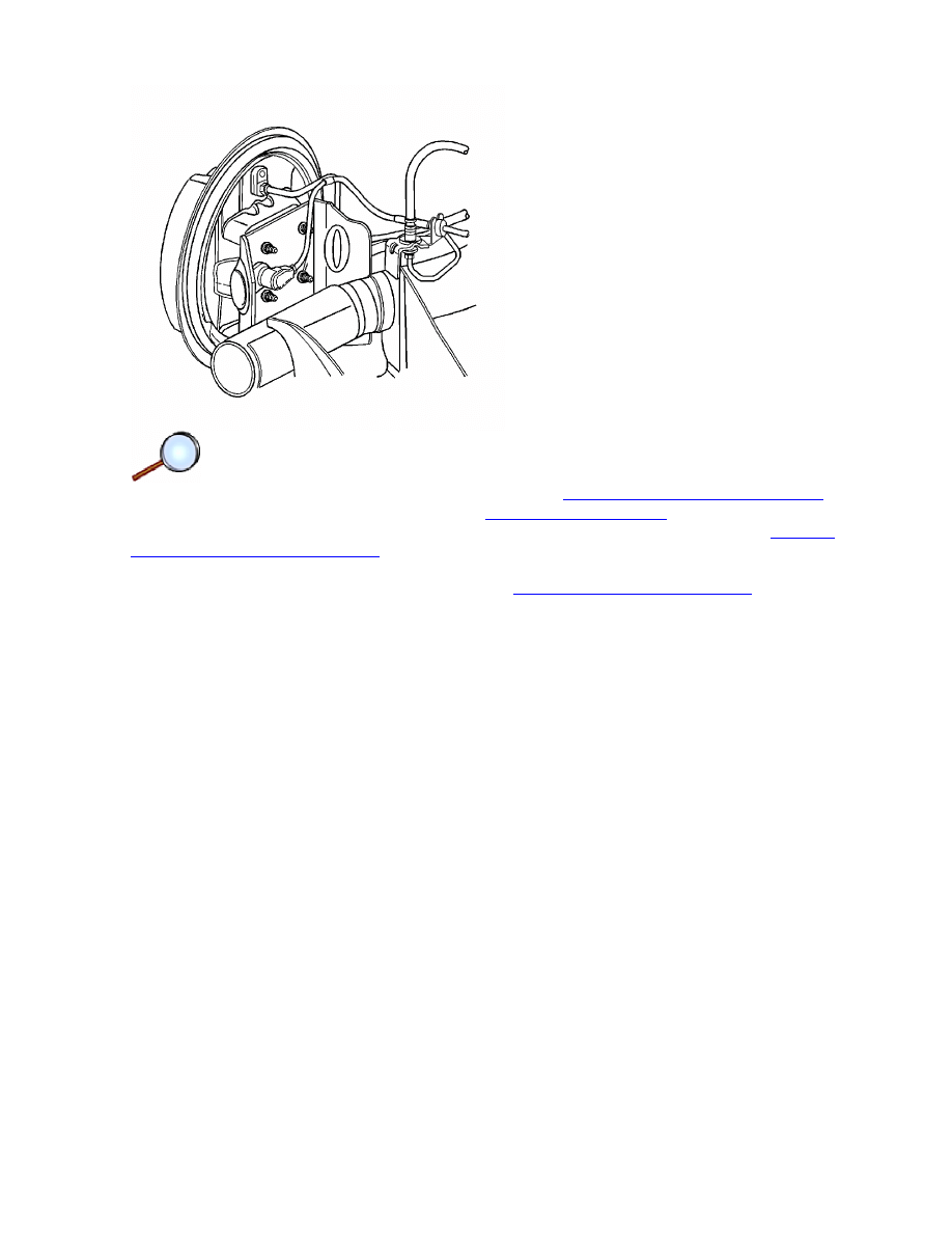
6. Remove the brake pipes from the brake hoses at the rear axle brackets. Cap or tape the
brake hose openings to prevent entry of foreign matter.
7. Remove the retaining clips from the brake hoses.
8. Unclip the brake hoses from the rear axle brackets.
9. Place support jacks under the arms of the rear axle and raise the rear axle arms slightly.
10. Remove the shock absorbers. Refer to
Shock Absorber Replacement
.
11. Lower the support jacks and remove the rear springs. Refer to
Coil Spring Replacement
.
12. Remove the left axle-to-bracket nut and bolt from the bracket. Pry the rear axle slightly, if
necessary.
13. Remove the right axle mounting bracket bolts from the underbody.
14. Remove the rear axle from the vehicle.
15. Remove the right axle-to-bracket nut and bolt from the bracket.
16. Remove the right axle bracket from the axle.
17. Remove the remaining drum brake components from the axle. Refer to
Rear Brake Backing
Plate Replacement
.
Installation Procedure
1. Install the backing plate and the wheel cylinder to the axle. Refer to
Rear Brake Backing Plate
Replacement
.
Page 2 of 4
Document ID: 1294241
7/6/2010
http://localhost:9001/si/showDoc.do?docSyskey=1294241&pubCellSyskey=56031&pubObj...
2. Install the right axle bracket to the axle.
3. Loosely install the right axle-to-bracket nut and bolt to the right axle bracket.
4. Raise and support the rear axle.
5. Loosely install the left axle-to-bracket nut and bolt to the left axle bracket.
6. Apply blue medium strength threadlocker, GM P/N 12345382, or equivalent, to the right axle
mounting bracket bolts.
Notice:
Refer to
Fastener Notice
in the Preface section.
7. Install the right axle mounting bracket bolts to the underbody.
Tighten
Tighten the axle mounting bracket bolts to 70 N·m (52 lb ft).
8. Install the rear springs and insulators. Refer to
Coil Spring Replacement
.
9. Install the shock absorbers to the axle with the lower attachment bolts. Refer to
Shock
Absorber Replacement
.
10. Install the brake hoses to the brackets on the rear axle.
11. Install the retaining clips to the brake hoses.
12. Install the brake pipes to the brake hoses.
13. Install the park brake cable to the rear axle. Refer to
Park Brake Cable Replacement
.
14. Install the brake shoes. Refer to
Brake Shoe Replacement
.
15. Connect the wheel speed sensor connector, if equipped.
Page 3 of 4
Document ID: 1294241
7/6/2010
http://localhost:9001/si/showDoc.do?docSyskey=1294241&pubCellSyskey=56031&pubObj...
16. Bleed the brake system and inspect for leaks. Refer to
Hydraulic Brake System Bleeding
.
17. If necessary, adjust the park brake. Refer to
Park Brake Adjustment
.
18. Lower the vehicle slightly and install the rear tire and wheel assemblies. Refer to
Tire and
Wheel Removal and Installation
.
19. Lower the vehicle.
20. Raise the vehicle on an alignment rack. Refer to
Lifting and Jacking the Vehicle
.
21. With the weight of the vehicle on the tires, tighten the lower shock absorber-to-axle bolts.
Tighten
Tighten the lower shock absorber-to-axle bolts to 72 N·m (53 lb ft).
22. Tighten the axle-to-bracket nuts and bolts.
Tighten
Tighten the axle-to-bracket nuts and bolts to 115 N·m (85 lb ft).
23. Lower the vehicle.
Page 4 of 4
Document ID: 1294241
7/6/2010
http://localhost:9001/si/showDoc.do?docSyskey=1294241&pubCellSyskey=56031&pubObj...
2008 Chevrolet Aveo
|
Aveo, Wave, G3, Barina (VIN S/T) Service Manual
|
Suspension
|
Rear Suspension
|
Repair Instructions
| Document ID: 1757779
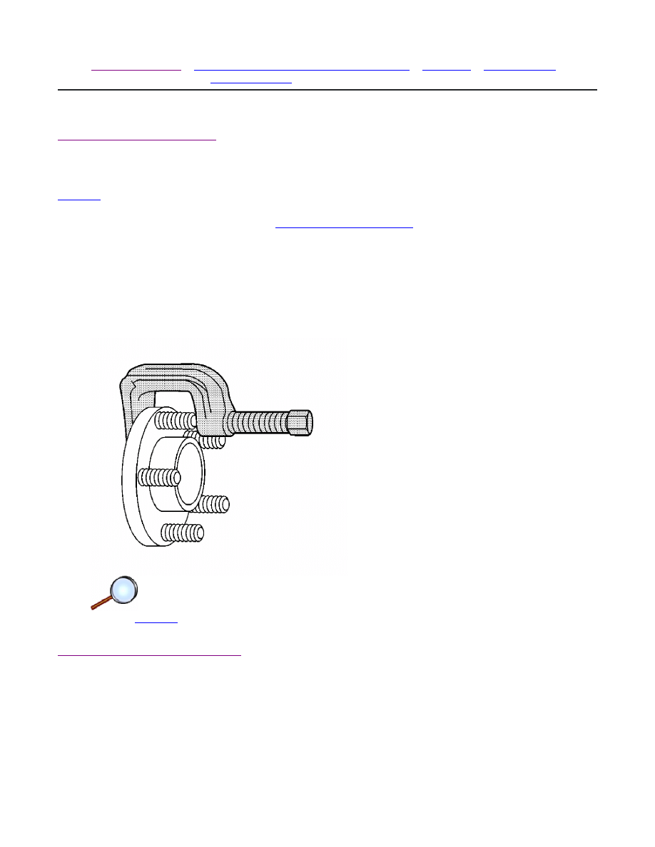
Wheel Stud Replacement
Removal Procedure
Tools Required
J 43631
Ball Joint Remover
1. Remove the brake drum. Refer to
Brake Drum Replacement
.
CAUTION:: If one stud is damaged, replace all the studs. A loose-running wheel may cause
only one stud to break, but the other studs could have internal fatigue. Replacing only the
broken stud and remounting the wheel may cause further damage and personal injury. If the
stud holes in the wheels have become enlarged or distorted, replace the wheel.
2. Install 2 wheel nuts onto 2 wheel studs.
3. Use a pry bar on the 2 nuts in order to prevent the hub from turning.
4. Use the
J 43631
in order to remove the stud.
Installation Procedure
© 2010 General Motors Corporation. All rights reserved.
Page 1 of 2
Document ID: 1757779
7/6/2010
http://localhost:9001/si/showDoc.do?docSyskey=1757779&pubCellSyskey=56045&pubObj...
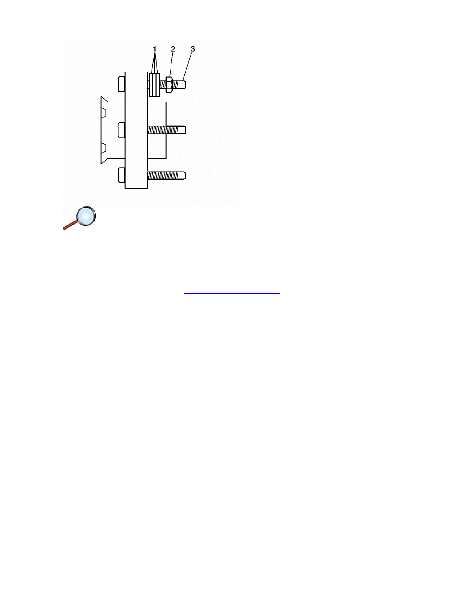
1. Install the wheel stud (3) into the stud hole.
2. Install 3 washers (1) and a wheel nut (2) onto the stud.
3. Install 2 wheel nuts onto 2 studs.
4. Use a pry bar on the 2 nuts in order to prevent the hub from turning.
5. Tighten the wheel nut in order to seat the stud.
6. Remove the 3 wheel nuts and the 3 washers.
7. Install the brake drum. Refer to
Brake Drum Replacement
.
Page 2 of 2
Document ID: 1757779
7/6/2010
http://localhost:9001/si/showDoc.do?docSyskey=1757779&pubCellSyskey=56045&pubObj...
Document Outline
Wyszukiwarka
Podobne podstrony:
M32d Rear Suspension
27 Rear Suspension
10 rear suspension
27 Rear Suspension
PIRVC Rear Suspension
M32d Rear Suspension
27 Rear Suspension
rear suspension 2
rear suspension
g3 rear suspension
27 Rear Suspension
Group 017 Rear Suspension
PIRVC Rear Suspension
ARTICLE SUSPENSION STABILIZER BAR REAR SERVICE
12 Rear Wheel Suspension
66 SUSPENSION REAR
ARTICLE SUSPENSION UPPER CONTROL ARM REAR SERVICE
więcej podobnych podstron