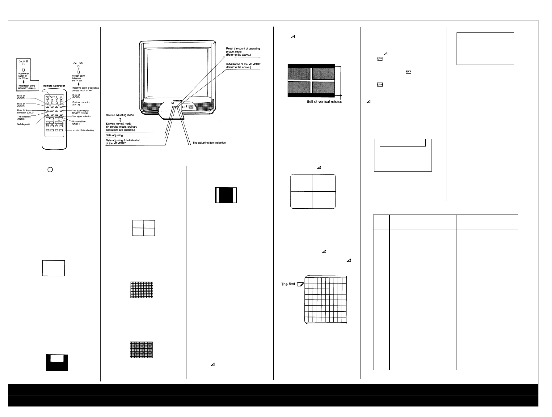
1. ENTERING TO SERVICE MODE
1) Press
button once on Remote Control.
2) Press
button again to keep pressing.
3) Keep pressing the
button, press MENU
button on TV set.
RCUT
S
32H
(Service mode dIsplay)
2. SELECTING THE ADJUSTING ITEMS
Every pressing of CHANNEL
▲
button changes
the adjustment items in the following order.
(
▼
button for reverse order.)
3. ADJUSTING THE DATA
Pressing of VOLUME
▲
or
▼
button will change
the value of data in the range from 00 to FF. The
variable range depends on the adjusting item.
4. NORMAL OPERATION ON THE SERVICE
MODE
Press MENU button on TV.
Adjustment mode
Service mode
RCUT
Address
S
32H
Data
5. EXIT FROM SERVICE MODE
Press POWER button on the remote control to
turn off the TV once.
General Information
Chassis: C5S
X-RAY RADIATION PRECAUTION
1. The E.H.T. must be checked every time the
receiver is serviced to ensure that the C.R.T.
does not emit X-ray radiation as result of
excessive E.H.T. voltage. The nominal E.H.T.
for this receiver is 27.8 kV at zero beam
current (minimum brightness) operating at
240V a.c. The maximum E.H.T. voltage
permissible in any operating circumstances
must not exceed 29.0 kV. When checking the
E.H.T., use the ‘High Voltage Check’ proce-
dure in this manual using an accurate E.H.T.
voltmeter.
2. The only source of X-RAY radiation in this
receiver is the C.R.T. To prevent X-ray
radiation, the replacement C.R.T. must be
identical to the original fitted as specified in
the Parts List.
3. Some components used in this receiver have
safety related characteristics preventing the
C.R.T. from emitting X-ray radiation. For
continued safety, replacement component
should only be made after referring the
Product Safety Notice below.
SAFETY PRECAUTION
1. This receiver has a nominal working E.H.T.
voltage of 24.5 kV. Extreme caution should be
exercised when working on the receiver with
the back removed. Do not attempt to service
this receiver if you are not conversant with the
precautions and procedures for working on
high voltage equipment. When handling or
working on the C.R.T., always discharge the
anode to the receiver chassis before removing
the anode cap. The C.R.T., if broken, will
violently expel glass fragments. Use shatter
proof goggles and take extreme care while
handling. Do not hold the C.R.T. by the neck
as this is a very dangerous practice.
Recommended Safety Parts
Item
Part No.
Description
2. It is essential that to maintain the safety of the
customer all cable forms be replaced exactly
as supplied from factory.
3. A small part of the chassis used in this
receiver is, when operating, at approximately
half mains potential at all times. It is therefore
essential in the interest of safety that when
serving or connecting any test equipment the
receiver should be supplied via a suitable
isolating transformer of adequate rating.
4. Replace blown fuses within the receiver with
the fuse specified in the parts list.
5. When replacing wires or components to
terminals or tags, wind the leads around the
terminal before soldering. When replacing
safety components identified by the interna-
tional hazard symbols on the circuit diagram
and parts list, it must be a Toshiba approved
type and must be mounted as the original.
6. Keep wires away from high temperature
components.
PRODUCT SAFETY NOTICE
Many electrical and mechanical components in
this chassis have special safety-related
characteristics. These characteristics are often
passed unnoticed by a visual inspection and the
X-ray radiation protection afforded by them
cannot necessarily be obtained by using
replacements rated at higher voltages or
wattage, etc. Components which have these
special safety characteristics in this manual and
its supplements are identified by the interna-
tional hazard symbols on the schematic diagram
and parts list. Before replacing any of these
components read the parts list in this manual
carefully. Substitute replacement components
which do not have the same safety characteris-
tics as specified in the parts list may create X-
ray radiation
Service Adjustments
GENERAL INFORMATION
All adjustments are thoroughly checked and
corrected when the receiver leaves the factory.
Therefore the receiver should operate normally
and produce proper colour and B/W pictures
upon installation. However, several minor
adjustments may be required depending on the
particular location in which the receiver is
operated.
This receiver is shipped completely in cardboard
carton. Carefully draw out the receiver from the
carton and remove all packing materials. Plug
the power cord into a convenient 240 volts 50
Hz AC two pin power outlet. Turn the receiver
ON. Check and adjust all the customer controls
such as BRIGHTNESS, CONTRAST and
COLOUR Controls to obtain natural colour or B/
W picture.
AUTOMATIC DEGAUSSING
A degaussing coil is mounted around the picture
tube so that external degaussing after moving
the receiver is normally unnecessary, providing
the receiver is properly degaussed upon
installation. The degaussing coil operates for
about 1 second after the power to the receiver is
switched ON. If the set is moved or faced in a
different direction, the power switch must be
switched off at least 30 minutes in order that the
automatic degaussing circuit operates properly.
Should the chassis or parts of the cabinet
become magnetized to cause poor colour purity,
use an external degaussing coil. Slowly move
the degaussing coil around the faceplate of the
picture tube, the sides and front of the receiver
and slowly withdraw the coil to a distance of
about 2 m before disconnecting it from AC
source. If colour shading still persists, perform
the COLOUR PURITY ADJUSTMENT and
CONVERGENCE ADJUSTMENTS procedures.
HIGH VOLTAGE CHECK
CAUTION: There is no HIGH VOLTAGE
ADJUSTMENT on this chassis.
1. Connect an accurate high voltage meter to
the second anode of the picture tube.
2. Turn on the receiver. Set the BRIGHTNESS
and CONTRAST Controls to minimum (zero
beam current).
3. High voltage will be measured below 29.0 kV
(2152DB), 32.0 kV (2857DB).
HEIGHT ADJUSTMENT
1. Receive the UK PHILIPS pattern, and set the
contrast to max, colour and brightness to
centre.
2. Adjust HEIGHT Control (R350) so that white
blocks at top and bottom of the picture are
just masked.
HORIZONTAL CENTRE ADJUSTMENT
1. Receive the UK PHILIPS pattern.
2. Adjust HPOS (Bus control) so the pattern
centre can be located at the screen centre.
FOCUS ADJUSTMENT
Adjust FOCUS Control on FLYBACK TRANS.
(T461) for well defined scanning lines in the
centre area on the screen.
SET-UP ADJUSTMENT
The following adjustments should be made
when a complete realignment is required or a
new picture tube is installed.
Perform the adjustments in order as follows:
1. Color Purity
2. Convergence
3. White Balance
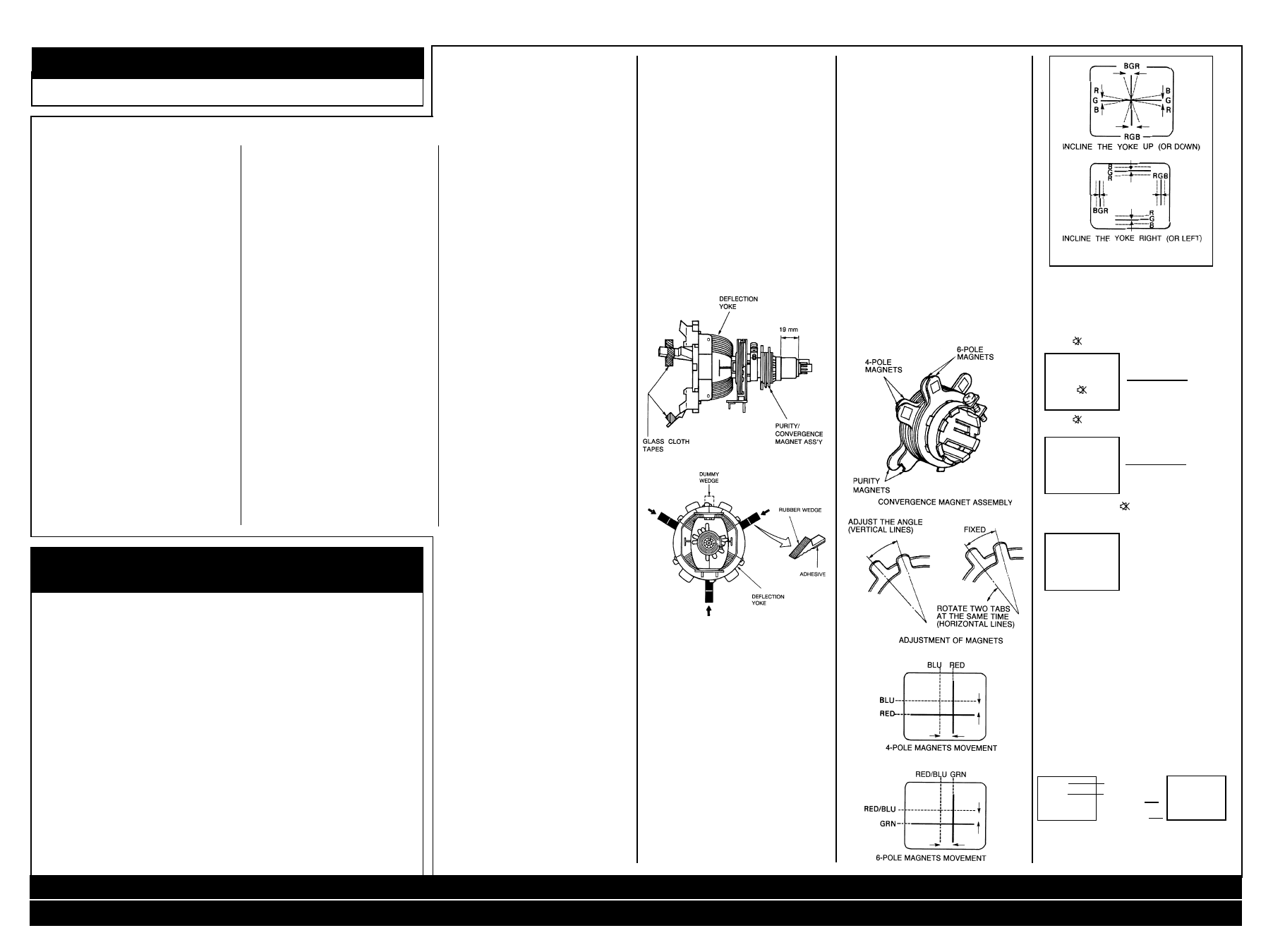
Note: The PURITY/CONVERGENCE MAGNET
assembly and rubber wedges need mechanical
positioning. Refer to figures
Safety Instructions
COLOR PURITY ADJUSTMENT
NOTE: Before attempting any purity adjust-
ments, the receiver should be operated for at
least fifteen minutes.
1. Demagnetize the picture tube and cabinet
using a degaussing coil.
2. Set the brightness and contrast to maximum.
3. Use a green raster from among the built-in
test signals.
4. Loosen the clamp screw holding the yoke and
slide the yoke backward or forward to provide
vertical green belt (zone) in the picture
screen.
5. Remove the Rubber Wedges.
6. Rotate and spread the tabs of the purity
magnet around the neck of the picture tube
until the green belt is in the center of the
screen. At the same time, enter the raster
vertically.
7. Slowly move the yoke forward or backward
until a uniform green screen is obtained.
Tighten the clamp screw of the yoke tempo-
rarily.
8. Check the purity of the red and blue raster.
CONVERGENCE ADJUSTMENTS
NOTE: Before attempting any convergence
adjustments, the receiver should be operated for
at least fifteen minutes.
CENTRE CONVERGENCE ADJUSTMENT
1. Use the cross-dot pattern from among the
built-in test signals.
2. Set the brightness and contrast for well
defined pattern.
3. Adjust two tabs of the 4-Pole Magnets to
change the angle between them and superim-
pose red and blue vertical lines in the center
area of the picture screen.
4. Turn the both tabs at the same time keeping
the angle constant to superimpose red and
blue horizontal lines at the center of the
screen.
5. Adjust two tabs of 6-Pole Magnets to superim-
pose red/blue line and green one. Adjusting
the angle affects the vertical lines and rotating
both magnets affects the horizontal lines.
6. Repeat adjustments 3, 4, 5 keeping in mind
red, green and blue movement, because 4-
Pole Magnets and 6-Pole Magnets have
mutual interaction and make dot movement
complex.
CIRCUMFERENCE CONVERGENCE
ADJUSTMENT
1. Loosen the clamping screw of deflection yoke
slightly to allow the yoke to tilt.
2. Temporarily put a wedge as shown. (Do not
remove cover paper on adhesive part of the
wedge.)
3. Tilt front of the deflection yoke up or down to
obtain better convergence in circumference.
Push the mounted wedge into the space
between picture tube and the yoke to fix the
yoke temporarily.
4. Put other wedge into bottom space and
remove the cover paper to stick.
5. Tilt front of the yoke right or left to obtain
better convergence in circumference.
6. Keep the yoke position and put another
wedge in either upper space. Remove cover
paper and stick the wedge on picture tube to
fix the yoke.
7. Detach the temporarily mounted wedge and
put it in another upper space. Stick it on
picture tube to fix the yoke.
8. After fixing three wedges, recheck overall
convergence. Tighten the screw firmly to fix
the yoke and check the yoke is firm.
9. Stick three adhesive tapes on wedges.
Service Mode General
Instructions
Dot Movement Pattern
Press
Press
➤
➤
➤
➤
➤
➤
C440
24082476
PF, 6600pF,
±
3%, 1500V
C463
24212152
CD, 1500pF,
±
10%
C801
24082363
PF, 0.22uF,
±
20%, AC250V
C813
24094656
CD,2200pF,
±
20%, AC400V
C814
24094656
CD,2200pF,
±
20%, AC400V
R327
24339569
MF, 5.6 ohm, 2W
R448
24338338
MF, 0.33 ohm, 1W
R801
24009954
Metal-Glazed Resistor, 2.2M ohm, 1/2W
R808
24019340
PTC Thermistor, 290V, 18 ohm
R890
24381333
OME, 33k ohm, 1/2W
R899
24005007
Metal-Glazed Resistor, 8.2M ohm, 1W
R920
24000940
FR, 2 ohm, 2W
R920
24000568
FR, 4.7 ohm, 1W
L462
-------------
DY, Supplied with V901
L901
23200205
Coil, Degaussing, TSB-2333AR
T401
23224983
Transformer, Horiz. Drive, TLN1039
T461
23236464
Transformer, Flyback, TFB41 23AR
T801
23211858
Line Filter, TRF3139
T862
23217287
Transformer, Converter, TPW3331AR
Q404
23314375
Transistor, ON4409(508D)
Q862
A8643108
Photo Coupler, TLP621(GR-LF
F470
23144875
Fuse, 0.63A
F801
23144507
Fuse, 3.15A
P801
23372012
Power Cord
S801
23145434
Switch, Power, 2C2P
V901A
23902067
Socket, CRT, 10P
V901
23312642
Picture Tube, A51EF543X69
V901
23312571
Picture Tube, A51EAL55X01
1
TOSHIBA 2152 DB
Safety Instructions / Safety Parts / Service Adjustments / Service Mode General Instructions / Service Mode Cont’d / Test Signal Selection
Adjustment of Video Chroma System / CRT Diagram / Text Diagram / AV Diagram / Main Diagram / Main Diagram Cont’d
Service Mode Cont’d
OTHER SERVICE FUNCTION
The following key entry during display of
adjustment menu provides special functions.
TEST SIGNAL SELECTION
Every pressing of button changes the test
patterns on screen as described below in
SERVICE MODE.
Signal off
➜
NTSC signals (14 patterns)
PAL signals (14 patterns)
About inside signal: The inside signal is output
at video input terminal from QA01, and is not
output with the pin inserted into terminal.
(Single color signal can be output.)
Signals
Red single colour
Green single colour
Blue single colour
Black single colour
White single colour
Picture
Using method
Purity and White uniformity of CRT
Red single colour.
Stopping G and B output of Q501
Green single colour.
Stopping R and B output of Q501
Blue single colour.
Stopping R and G output of Q501
Black single colour.
Making black signal of approx. 1Vp-p in QA01
White single colour.
Making white signal of approx. 1Vp-p in QA01
Signals
W/B adjustment
Picture
➜
➜
➜
Using method
White balance adjustment
White part.
White balance adjustment/check in light area.
Black part.
White balance adjustment/check in dark area.
Making. approx. 1Vp-p signal in QA01.
Signals
Black cross-bar
White cross-bar
Picture
Using method
Picture position (horizontal, vertical and slant) in
CRT adjustment.
Making approx. 1 Vp-p signal in QA01.
Signals
Black cross-hatch
White cross-hatch
Picture
Using method
Convergence and vertical amplitude adjustment
Making approx. 1 Vp-p signal in QA01.
Signals
Black cross-dot
White cross-dot
Picture
Using method
Convergence adjustment
Making approx. 1Vp-p signal in QA01.
Signals
H signal (Left, right, white)
H signal (Left, right, black)
Picture
Using method
For checking (of purity drift) of white uniformity
of CRT H signal (Left, right, white).
Check in light area.
H signal (Left, right, black).
Check in dark area.
The adjustment will be the best, if the time when
unevenness of colour in light area occurs, is a
little longer than that in dark area.
Making approx. 1Vp-p signal in QA01.
ITEM:
Initialisation of QA02 (Memory)
ADJUSTMENT PROCEDURE:
After replacing QA02, the following initialisation
is required.
1. Call up the adjustment mode display following
the steps 1 and 2.
2. Press the CALL button on the Remote Control
and CHANNEL
▲
buttons on the TV set
simultaneously. The initialisation of QA02 has
been completed.
3. Check the picture carefully. If necessary,
adjust any adjustment item.
Perform “AUTOMATIC SEARCH MEMORY”
ITEM: SUB-BRIGHTNESS (Address: BRTC)
ADJUSTMENT PROCEDURE:
1. Set CONTRAST to “00,, and BRIGHTNESS
to “50” by adjusting user controls.
2. Set the TV in service mode to get white cross-
bar of inside pattern.
3. Select BRTC (brightness correction), and
adjust the
- / + button to reduce the value
so that white portion of inside pattern slightly
light.
4. Rotate R350 to show the belt of vertical
retrace. See next figure.
5.Adjust
- / + button to increase the data
value of BRTC, and set it just before the
difference between the belt of vertical retrace
and the border of black portion of inside
pattern is visible. After that, return vertical
height and contrast.
ITEMS:
HORIZONTAL POSITION ADJUSTMENT
(HPOS)
VERTICAL POSITION ADJUSTMENT (VPOS)
ADJUSTMENT PROCEDURE:
1. Set the TV in service mode, and get black or
white cross-bar signal with VIDEO button on
remote hand unit.
2. Select either HPOS (Horizontal picture
phase) or VPOS (Vertical picture phase) with
CHANNEL
▲
,
▼
buttons, and adjust horizon-
tal or vertical picture position in the center of
screen with VOLUME
- / + buttons.
ITEM:
VERTICAL AMPLITUDE ADJUSTMENT (HIT)
ADJUSTMENT PROCEDURE:
1. Set the TV in service mode, and get black or
white cross-hatch signal with VIDEO button
on remote hand unit.
2. Select HIT (Vertical amplitude) with CHAN-
NEL
▲
,
▼
buttons, and adjust vertical
amplitude with VOLUME
- / + buttons so
that vertical amplitude lacks a little.
3. Adjust vertical amplitude with VOLUME
- /
+ buttons so that the first bar on cross-hatch
signal touches edge of screen.
WHITE BALANCE ADJUSTMENT
CUTOFF ADJUSTMENT
(RCUT)
(GCUT)
(BCUT)
DRIVE ADJUSTMENT
(GDRV)
(BDRV)
1. Set Contrast to 40, and brightness to +20 by
picture control.
2. Set the TV in service mode, and get the inside
W/B adjusting signal with VIDEO button.
3. Select RCUT, GCUT and BCUT with CHAN-
NEL
▲
,
▼
buttons, to set individual values to
32, and to set GDRV and BDRV to 20 with
VOLUME
- / + buttons.
4. Press
button on the remote control and
rotate Screen VR to get one slight horizontal
line on screen.
Note:Every pressing of
button provides
Horizontal line picture and Normal picture
alternately.
5. Press
button to release horizontal line
picture, and select the two other colours
which did not light in the above step with
CHANNEL
▲
,
▼
buttons. Then tap VOLUME
- / + buttons so that three colours slightly
light in the same level.
To correct white balance in light area, select
GDRV and BDRV with CHANNEL
▲
,
▼
buttons
to adjust.
To correct white balance in dark area, perform
fine adjustment of RCUT, GCUT and BCUT.
Light area check (to show white)
Dark area check (to show black)
SELF DIAGNOSTIC FUNCTION
1) Press “9” button on Remote Control during
display of adjustment menu. The diagnosis
will begin to check if interface among IC’s are
executed properly.
2) During diagnosis, the following displays are
MULTI BUS E2PROM ADDRESS, ADJUSTING ADDRESS TABLE
Adjusting
QAO2
Name
Value of initializing
method
memory
of
QAO2
Adjustments
address
item
(Hexa-decimal)
S
06B
OSD
60
OSD POSITION
06C
OPT
07
OPTION
F
06D
RCUT
32
R
CUT OFF
06E
GCUT
32
G
CUT OFF
06F
BCUT
32
B
CUT OFF
070
GDRV
20
G
DRIVE
F
071
BDRV
20
B
DRIVE
S
072
CNTX
39
SUB CONTRAST MAX
F
073
BRTC
40
SUB BRIGHT CEN
076
COLP
32
SUB COLOUR CEN PAL
F
077
COLS
32
SUB COLOUR CEN SECAM
S
078
CNTC
2D
SUB CONTRAST CEN
079
CNTN
20
SUB CONTRAST MIN
07A
BRTX
12
SUB BRIGHT MAX (DIFFERENCE)
07B
BRTN
10
SUB BRIGHT MIN (DIFFERENCE)
070
COLX
40
SUB COLOUR MAX
07D
COLN
10
SUB COLOUR MIN
082
5T4
19
SUB SHARP CEN OTHER (TV)
083
5V4
19
SUB SHARP CEN OTHER (VIDEO)
084
TXCL
4A
TEXT CONTRAST LEVEL
086
VM0
05
VCD MODE DATA
087
WCTL
00
APRO MODE DATA
08E
WON
2D
WOOFER AUTO LOUDNESS
097
EMX
FC
NICAM ON LEVEL
098
EMN
64
NICAM OFF LEVEL
099
FMA
00
FM ATTENUATOR LEVEL
S
09A
STS
00
STEREO SEPARATION
F
09B
HPOS
08
50Hz H-POSITION
S
09E
HPS
04
60Hz/50Hz H-POSITION (DIFFERENCE)
F
0AF
PID
11
PAL IDENT LEVEL
0B0
TRP
01
CROMA TRAP f0
S
0B1
DLY0
07
Y DELAY TV SECAM (BG)
0B2
DLY1
07
Y DELAY TV SECAM (OTHER)
0B3
DLY2
07
Y DELAY VIDEO SECAM
0B4
DLY3
04
Y DELAY TV OTHER (BG)
0B5
DLY4
04
Y DELAY TV OTHER (DK, I)
0B6
DLY5
05
Y DELAY TV OTHER (M,N)
0B7
DLY6
05
Y DELAY TV OTHER (VIDEO)
S ... semi-fixed data area which is fixed by model. (Do not adjust in field service.) F ... This item may require
adjustments by models after initialization, when QAO2 is replaced.
shown.
(SELF CHECK)
(1)
23904981
(2)
POWER
:
00
(3)
BUS LINE
:
OK
(4)
Bus CONT
:
OK
(5)
BLOCK
:
UV V1 V2
QV01
1) Part number of microcomputer (QA01)
2) Operation number of protecting circuit ----“00”
is normal. When indication is other than “00”,
overcurrent apts to flow, and circuit parts may
possibly be damaged.
3) BUS LINE CHECK ---- “OK” is normal.
“SDA1-GND” means that SDA line is shorted
to ground.
“SCL1-GND” means that SCL line is shorted
to ground.
“SCL1-SDA1” means that SDA line is shorted
to SCL line.
4) BUS CONT----“OK” is normal.
When indication shows “Q OOO NG”, the
device with the number may possibly be
damaged.
5) BLOCK
UV : TV reception mode
V1: VIDEO 1 input mode ( 1)
V2 :VIDEO 2 input mode ( 2)
Indicated color of mode now selected: Green
and Red
Indicated color of other modes: White
Green: Normal
Red: The microcomputer operates to provide
judgement of no video signal. The red color is
still indicated though the signal is input, failure
may exist in input signal line including QV01.
QV01: In case of indication green --- Normal
In case of indication red with input signal ----
Failure may exist in output line including QV01.
2
TOSHIBA 2152 DB
Safety Instructions / Safety Parts / Service Adjustments / Service Mode General Instructions / Service Mode Cont’d / Test Signal Selection
Adjustment of Video Chroma System / CRT Diagram / Text Diagram / AV Diagram / Main Diagram / Main Diagram Cont’d
Item
Name
Setting(User control)
Input signal
Measurement point
Adjustment procedure
Adjustment standard
Slave
SUB
Contrast: MAX
Sub-bright
Screen
1. This adjustment must be done
5
±
1.5
address 36
BRIGHT
Bright: CENTER
signal
adjustment
after [BRTC], screen VR and white balance adjustments
[BRTC]
CENTRE
Color: MIN
have been completed.
2. Adjust number of black collapse lines of sub-bright
signal.
Slave
SUB
Contrast: MAX
Sub-bright
IC501
1. Select slave address 39
1.4V(p-p)
address 39
COLOUR
Bright: CENTER
signal
#23...
[COLP].
±
0.2V(p-p)
[COLP]
PAL
Color: CENTER
(PAL)
(B-OUT)
2. When [COLP] is selected, Y-signal is muted
and only color signals are outputted.
3. Adjust amplitude of the upper half of the colour
bar output.
Slave
Screen
1. Set the controls as shown in
address
adjustment
the left column.
20[RCUT]
R cut-off
RCUT 32 Hexa-decimal
2. Gradually increase the screen
31[GCUT]
G cut-off
GCUT 32 Hexa-decimal
VR (T461) until one of R, G or B line begins
32[BCUT]
B cut-off
BCUT 32 Hexa-decimal
to brighten slightly.
Screen VR
Screen
GDRV 20 Hexa-decimal
3. Determine the position of the screen VR here.
BDRV 20 Hexa-decimal
4. Adjust RCUT, GCUT and BCUT, brighten other lines
Select horizontal line mode by
until they begin to light slightly.
pressing
-I- - button on the remote
(Adjust DATA so that the line becomes almost white.)
control in service mode.
5. Press
-I-- button on the remote control to escape from the
horizontal line mode.
30[RCUT]
R cut-off
Contrast: MAX
White, etc.
Screen
1. This adjustment must be done
HIGH LIGHT;
31[GCUT]
G cut-off
Bright : CENTER
adjustment
after adjustment of the above-
(103cd/m
3
)
32[BCUT]
B cut-off
Color : CENTER
mentioned cut-off and screen
7195K
33[GDRV]
G drive
VR’s have been completed.
-0.005uv [BDRV]
34[BDRV]
B drive
2. Adjust cut-off and drive DATA
DARK;
(White
alternately.
(17cd/m
3
)
balance)
3. Use a checker to adjust
7695K
±
0uv
brightness by changing modulation factor.
Slave
ID
VIDEO
Pin 52 of IC501
1. Connect a resistor 220k ohm
2.0V DC
address
ref
No input
across pin 52 of IC501 and
±
0.1V DC
F0 PID
GND and connect digital
voltmeter.
2.Select slave address F0 PID.
3.Adjust DC voltage.
Slave
Chroma
Contrast: MAX
PAL
Pin 23 of
1.Select slave address F1 TRP
Chroma level:
address
trap f
0
Bright : MIN
colour bar
IC501
2. Adjust chroma trap so that
MIN
F1 TRP
adjusting
Colour: MIN
(B-OUT)
chroma level at pin 23 of
IC501 becomes minimum.
ADJUSTMENT OF VIDEO-CHROMA SYSTEM
(Factory Adjustment)
Model Name: S5E
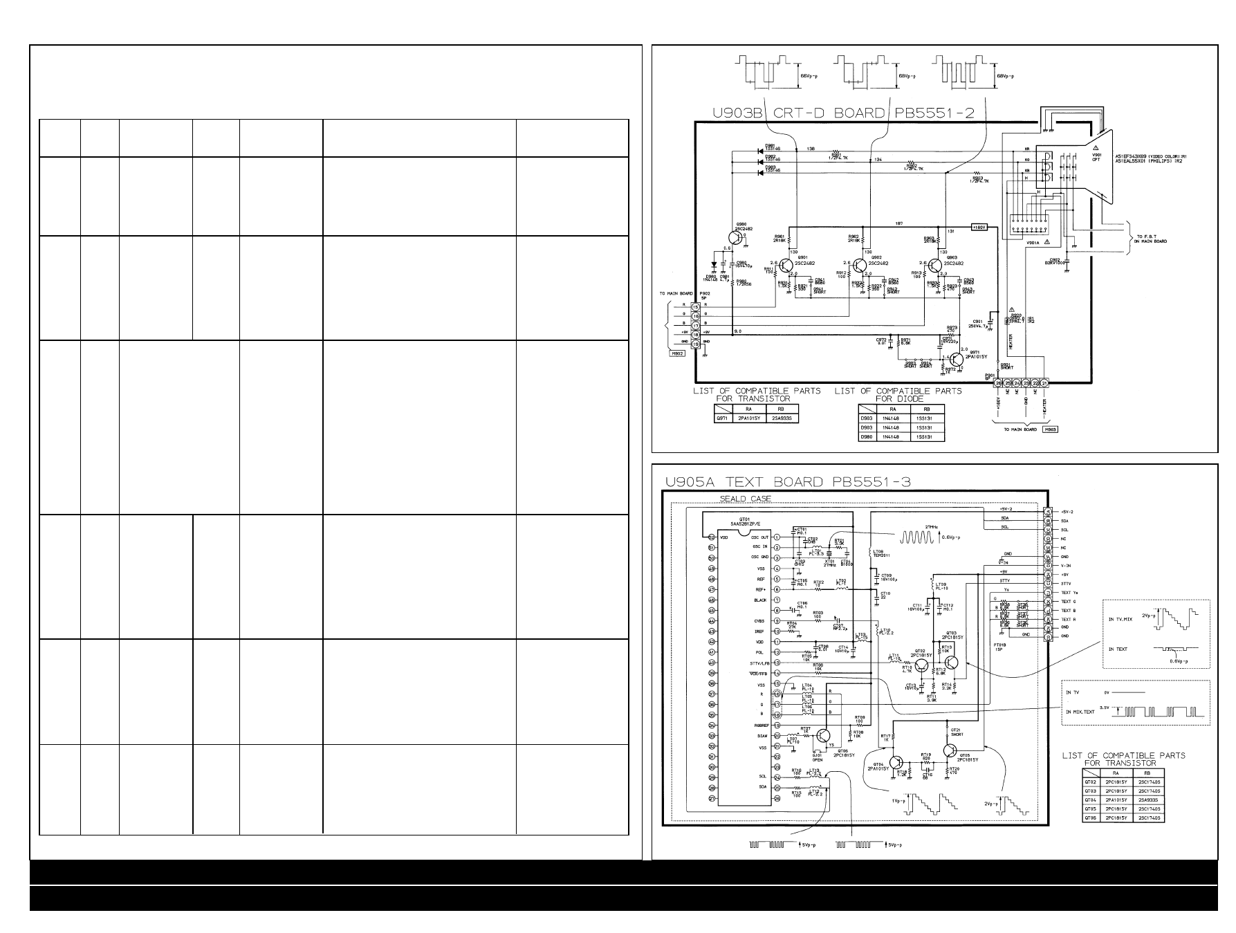
CRT Diagram
Text Diagram
3
TOSHIBA 2152 DB
Safety Instructions / Safety Parts / Service Adjustments / Service Mode General Instructions / Service Mode Cont’d / Test Signal Selection
Adjustment of Video Chroma System / CRT Diagram / Text Diagram / AV Diagram / Main Diagram / Main Diagram Cont’d
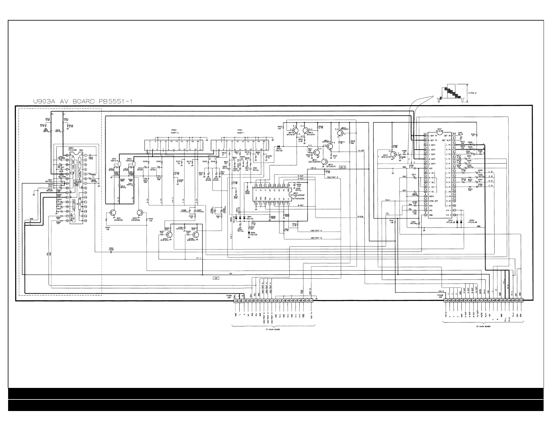
AV Diagram
Safety Instructions / Safety Parts / Service Adjustments / Service Mode General Instructions / Service Mode Cont’d / Test Signal Selection
Adjustment of Video Chroma System / CRT Diagram / Text Diagram / AV Diagram / Main Diagram / Main Diagram Cont’d
4
TOSHIBA 2152 DB
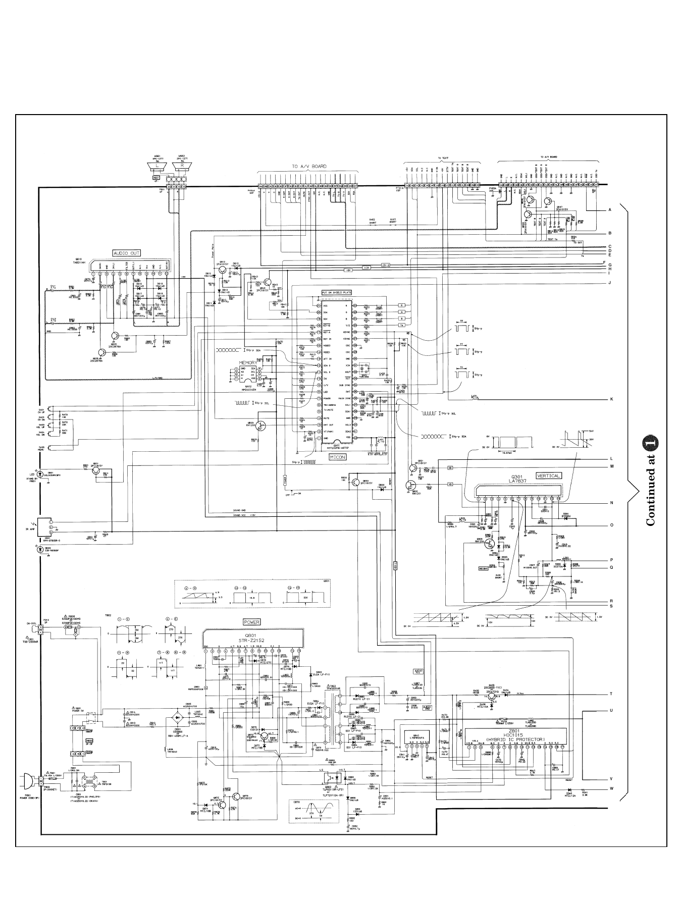
Main Diagram
5
TOSHIBA 2152 DB
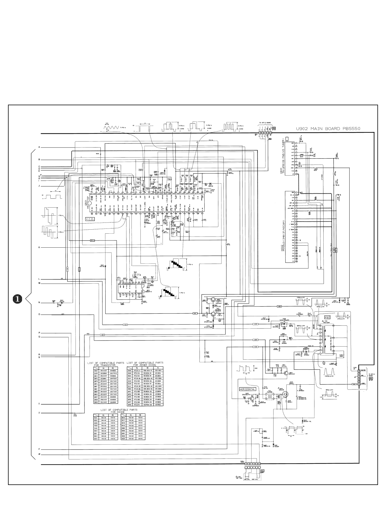
Main Diagram Cont’d
6
TOSHIBA 2152 DB
Wyszukiwarka
Podobne podstrony:
Grundig Tv Super Color 8613 FR Schematy
Philips 15GR2330 Color TV
Schematy instalacji TV naziemnej i satelitarnej w domku jedno
Schematy instalacji TV naziemnej i satelitarnej w domku jedno.. 3
Curso dicas tv LCD Toshiba
CHINA 32 LCD TV SCHEMATIC
Toshiba 2163Db Schematic
Hitachi Tv Cl2560,2860,2564,2864 Schematic
Color Schematics
6 China Mini LCD TV Schematic (MC802 LA7605N)
Hitachi Tv 1408Rx,1408Ty Schematic
Service Manual Sony TFT LCD Color Monitor CPD L133 Schematic
06 pamięć proceduralna schematy, skrypty, ramyid 6150 ppt
7 aglebra schematow bloczkowych
wZ 2 Budowa wiedzy społecznej teoria schematów
3 ogolny schemat replikacji i onkogeza DNA wirusowa
Schematy animacji
więcej podobnych podstron