
1
MZ250 Race Preparation
for the financially challenged
Introduction...............................................................................................................................................2
Engine .......................................................................................................................................................2
Bottom end............................................................................................................................................2
Top end .................................................................................................................................................3
Exhaust..................................................................................................................................................8
Ignition................................................................................................................................................10
Carburettor ..........................................................................................................................................10
Frame ......................................................................................................................................................11
Footrests..............................................................................................................................................11
Engine Mounts ....................................................................................................................................12
Fork yokes and headstock, Forks, Rear shocks ..................................................................................12
Wheels and tyres, Brakes ....................................................................................................................14
General preparation.................................................................................................................................15
Information .............................................................................................................................................16
Book References .................................................................................................................................16
Suppliers .............................................................................................................................................16
Table: Piston displacement .................................................................................................................17
An interesting discussion on tyres and handling.................................................................................18
Acknowledgements.............................................................................................................................19

2
Introduction
The aim of this guide is to give some practical advice on building an MZ250 for racing in
the BMCRC MZ250 class. The regulations for 2002 season are used as a guideline. It is
not intended as a tuning reference so the settings and timings are for example only, but
are mostly workable – I have to say that because mistakes can be very expensive in this
game! Some definitive theory books are listed at the end.
The MZ formula is simple - basically stock carburettor, stock exhaust header and diffuser
cone, max diameter of expansion chamber no more than stock, and clutch must be crank-
mounted as stock. Other standard parts specified, like barrel, head, cases, frame etc. but
some parts are ‘open’ eg wheels, brakes and tyres.
Engine
Bottom end
Crank stays more or less standard - some people lighten and rebalance the crank wheels
but it is lots of work for little gain in this class. The best place to spend the effort is
making sure it gets assembled properly, perfectly true and check it for out-of-round.
Bigend needs to be replaced with a silver plated cage type for racing (£20), to a conrod
that has been checked for damage. The standard (original MZ) rod has proved perfectly
reliable, but the crankwheels can be modified to accept a japanese rod and bearing kit
which some prefer. Fit new little end, main bearings and crankcase seals.
Most people take a lot of weight off the clutch which is crank-mounted and very heavy –
show it to a machinist or a tuner and ask them to shave it, which makes the engine more
responsive but it is optional, at least to start with. The clutch has a tendency to work
loose from the taper, and then ruin the taper in the boss (clutch centre) and the
lightening might help this. Best prevention is to make sure the taper is perfectly clean
and undamaged on assembly, and then tightened fully using a suitable locking tool to
prevent the crank turning (see suppliers list). If it is scored then replace it. It can be
modified to key the boss to the crankshaft which guarantees the thing stays put.
Gearbox should be refurbished while the cases are apart - simple enough, no real
modifications necessary except that 3
rd
gear suffers from a slight design defect that can
be rectified with some attention from a specialist – see Burwins or Holmshaw. Change
ALL the bearings (they really don't cost much), the oil seal, and check the thrust
washers, selector forks and gear teeth for condition. Replace anything less than perfect
because they get punishing stress in racing. The little layshaft bearing in the blind hole
can be removed easily by heating the case evenly to about 150 celsius, when it will
literally fall out: clean the case thoroughly, wait till the wife (or other likely objector) is
about 5 miles away and put it in the oven, face down on a tray. Open the windows, give it
15 minutes at gas 5, and you will hear it hit the tray. Drop the new one in while it is hot.
Gearchange action can be a bit fickle on these boxes, so pay attention to the condition of
the 'detent roller' which is the indexing roller on a sprung lever arm in the primary drive
case. It lives behind the driven primary gear. Replace it if it looks burred over.
3
Top end
The MZ piston goes in the bin. It is far too heavy, has too many rings and is made of
spat-out cardboard or something equally unsuitable for racing. The best piston material
and manufacturers are Japanese but there are a number of patterns to choose: the type
of piston depends on whether you go piston-ported or reed valve in your tune - whichever
you choose you need a 70mm nominal size (69.5 is the MZ standard) with an 18mm
gudgeon pin.
Get the barrel bored to match the new piston with a 0.08mm diametral clearance. Be
fussy and state you want a careful job, sparked off (honed) to exactly parallel in the bore,
exactly perpendicular to the cylinder bottom face (not the liner spigot).
The Suzuki TS250 piston has two rings, about 1.3mm thickness which is good for roughly
8000 rpm and has a long skirt for piston porting. The RM250E piston has a single 1mm
ring which is good for 9500 rpm, has a shorter crown height and skirt length which is OK
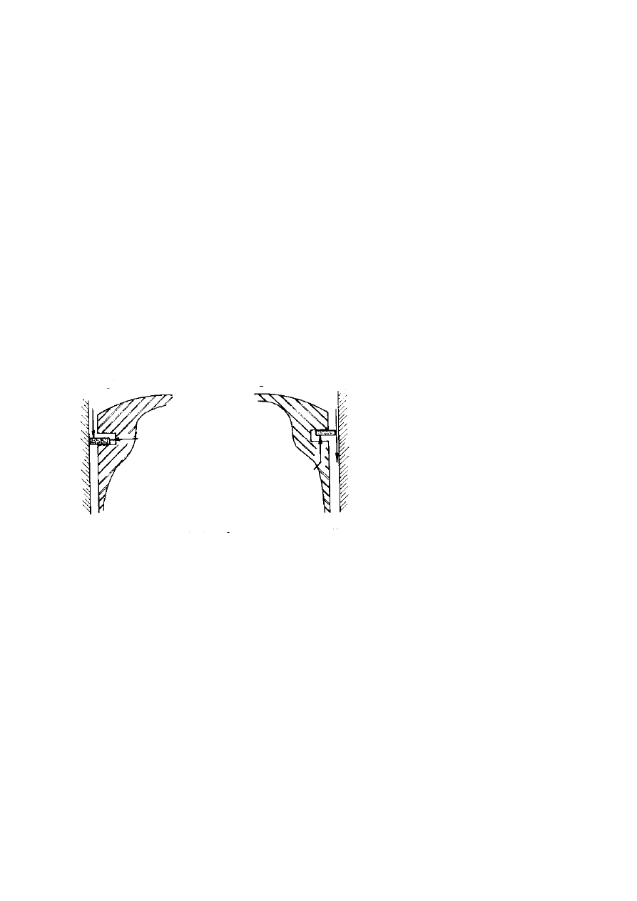
for reed valve use. One of the speed-limiting factors is ring thickness, which determines
what speed ‘ring flutter’ sets in but 8k is fine (see below).
pictured left, piston ring with proper gas
seal formed when ring is in contact with
lower land and combustion pressure can
reach behind it
pictured right, ‘flutter’ condition is when
acceleration forces at TDC exceed pressure
forces and ring leaves lower land. Sealing
thrust against bore is lost – pressure can
escape .
Both can be run with one ring to reduce friction, if 20:1 fuel/oil mixture is used to
maintain good compression seal (this mixture is the subject of great debate). But the pipe
and carb sizes allowed will not flow much more than 8500 rpm. I use the RM piston and
a reed valve from a RD350 and I can get it to rev on to over 9000, without useful power
up there but it makes the motor nice and flexible.
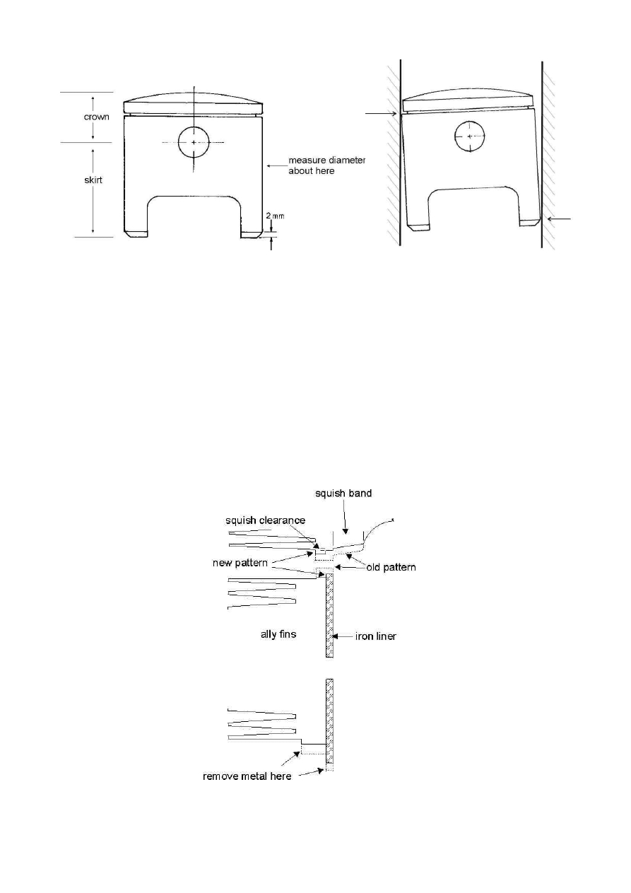
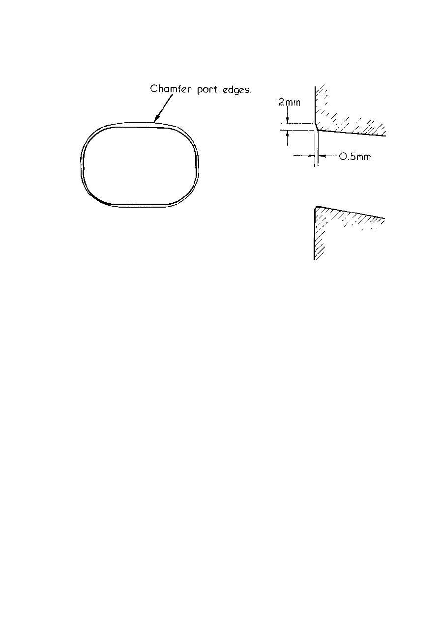
Prepare the piston by chamfering the edges of the skirt, 2mm deep (LH diagram, below).
Very carefully stress-relieve the whole outer edge of skirt and pin boss, by filing smooth
any nicks and sudden changes in section of the casting. Finish the worked areas with
1200 wet-or-dry using plenty of kerosene, white spirit or thin oil (WD40?) as a lubricant.
Relieve the top ring land slightly also, at least along the exhaust-facing edge as this
bears the thrust here (RH diagram) and can scuff up as the piston wears - the piston
rocks forwards on the power stroke, and you need to make sure the pressure (thrust) is
shared by the bottom of the skirt on the inlet side and the face just below the ring lands.
4
Pictured left, piston details. Pictured right, correct thrust points for a ‘rocking’ piston – crown must be
relieved to allow this
When the piston is chosen the barrel has now got to be shortened at both ends to make
up for the different piston skirt and crown height. The basic principle is to set the
exhaust port height by removing metal from the top of the barrel (do this after any
reshaping to the top of the port), and then set the piston to its correct TDC position ('deck
clearance') by shaving at the bottom. This bottom face has to be turned true to the bore
so be particular about it. The liner spigot (the part of the iron cylinder liner that locates
in the crankcases) must be shortened also to match the cases - decide whether to use a
gasket, and what type, and account for this in the measurement. Personally I don’t use
any gaskets at all, just a good quality sealant like Wellseal and carefully prepared
surfaces. These measurements have to be exact so spend a good deal of time over it,
using modelling clay to take moulds of clearances etc.
5
Then the inlet port needs to be modified - it will need moving upwards - using metal
epoxy (eg Devcon ‘F’ aluminium putty) to build up the floor to give your chosen port
timing, and a die grinder or a Dremel (a flexible shaft in a drill doesn’t really go fast
enough) to remove metal from the roof. There are arguments about whether to leave
some of the cylinder liner 'tongue' in place, which serves to improve the piston thrust-
face contact with the liner on the road machine as it passes the port which of course is on
the thrust side of the barrel for a forward-rotating engine but I am of the opinion that
the pistons wear too fast on a racing machine for this to be of much benefit. Make a
spigot at the top of the barrel for mating to the head by machining so the liner protrudes
by 1-2mm or so from the top face - see head preparation later.
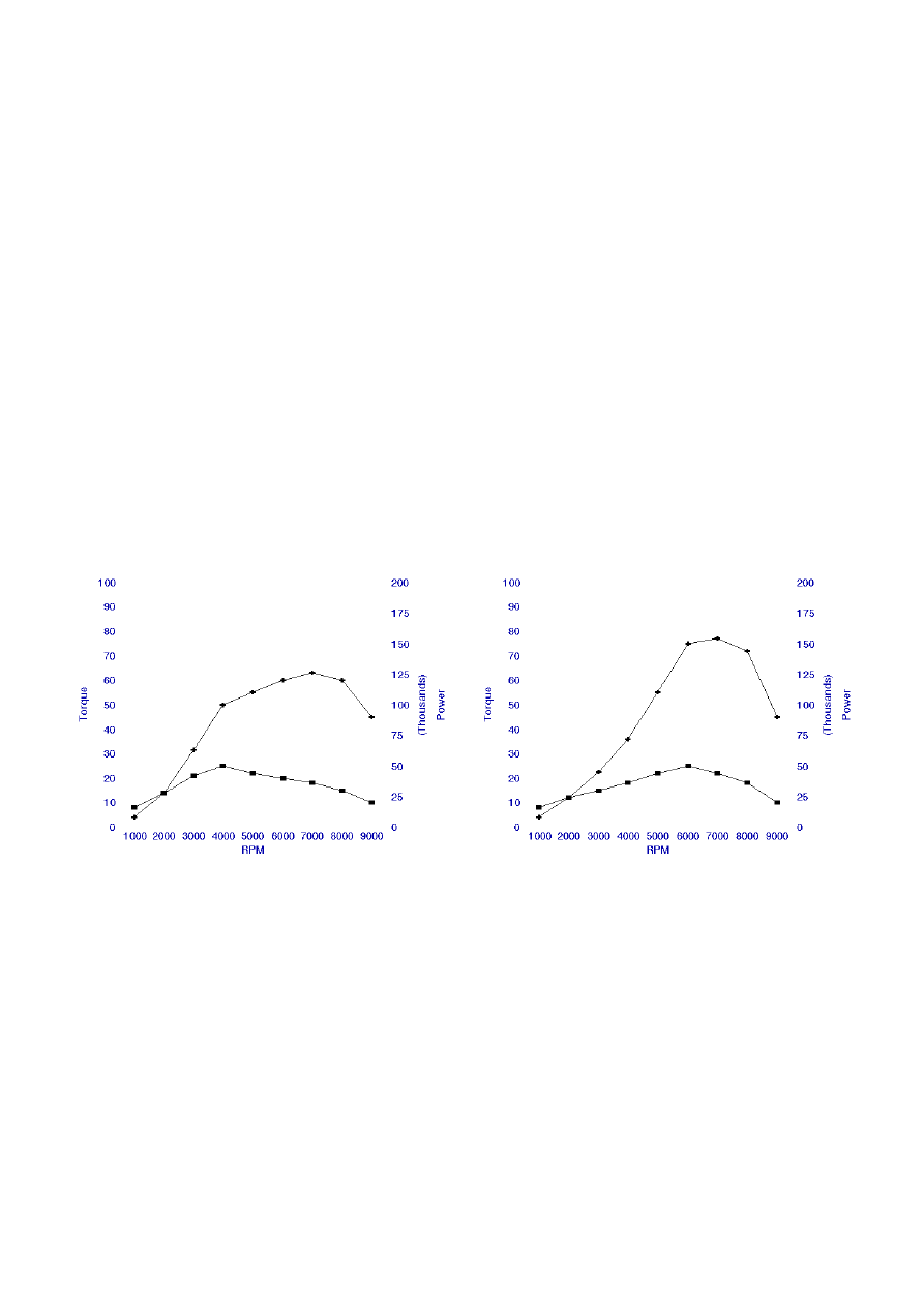
For a piston-controlled inlet port the usable range for timing is probably 155 to 175
degrees total ‘open’ duration.. There are many schools of thought, but the setting affects
the cylinder filling efficiency as a function of speed, and increasing the duration has the
effect of moving the torque peak up the speed scale. As power itself is the product of
torque and speed, the shape of the power peak (and thus the tractability of the engine) is
directly affected by the port timing. The diagrams below illustrates this (with kind
permission of John Wood and Rob Carrick, ‘Villiers Singles Improvements Handbook’) –
note the maximum torque has not changed in magnitude between the diagrams, but its
changed position has affected the power delivery markedly.
As with most tuning parameters, the relationship between torque and port timing is not
simple, and other factors need to be considered as the carburettor, inlet tract, port and
crankcase space act as a resonant cavity with the pulses of air movement in the system.
It really does warrant some extra reading. All this also affects the jetting requirement –
for example I use a 240 main in my reed-valve engine, but some of Tony Holmshaw's
piston-port tunes use 200 and some Burwin's use less than 150 - it is an effect in the
carburation that causes this, called 'loading-up' or 'triple-carbing' at low speeds .. reed
valves don't do it so the fuel delivery requirements are totally different.
The exact shape of the inlet port tract is down to how much work you can put in to it,
regarding the above, but as a guide it needs to point downwards for good flow, and the
port opening wants to be no less than 90% of the cross-sectional area of the carburettor,
but no more than 120%. Theoretically, if an air passage such as the inlet tract is 'necked'
slightly at a transition, like the opening at the cylinder wall, the velocity is increased and
the turbulence is less detrimental, which can give good flow but at the same time a
6
gradual taper outwards along the length increases the flow capacity (reduces the effect of
turbulence at the walls of the passage). Ideally the two should be combined but make
sure the passage does not have any sudden changes of shape, nor bulge out unnecessarily
as the stream velocity will drop at the wide spots causing fuel ‘drop-out’ (basically it
condenses onto the walls, coming out of the mixture) and further turbulence, which is
bad for the gas flow. Also, a slightly rough finish to the walls of the inlet tract will
improve flow by causing micro-turbulence along them, which actually reduces drag at the
boundary – it is a bit like a cushion of already-moving air – so don’t polish them finely,
just use emery paper in small circular movements.
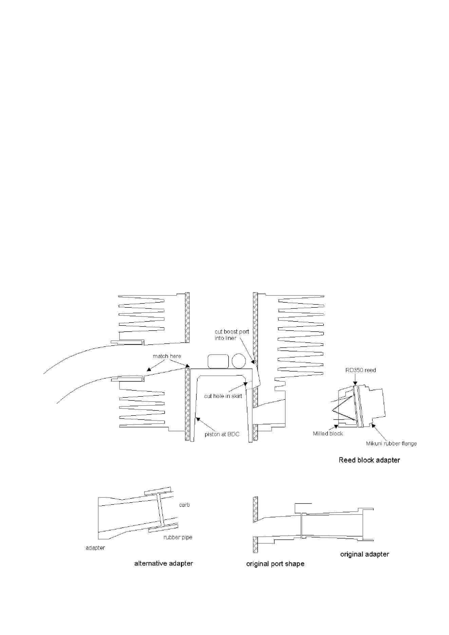
Now you need a means of attaching the carburettor. It needs a short pipe and some sort
of flange: some people use the original connector and chop it down, re-angling the carb at
the same time because now it won't clear the crankcases (the barrel has been shortened!)
or weld a pipe to a flat plate, bolt up and glue this to the barrel and use a hose to attach
the carb to the pipe. It needs to be bored out to match the bored-out carb (see later) and
carefully matched to the barrel opening.
This is where the reed block goes if you are using one - it needs to be mounted close up to
the barrel so as not to leave a large chamber behind the piston, so pick a reed cage that is
not too wide or you will end up breaking into the stud drillings when machining out the
cavity for it to fit into. Best of luck if you are doing this, it is not easy to get it to fit and
not leak!
7
The face of the barrel will need to be 'flattened' at the port opening to take your flange or
reed block (unless you are using the original connector). You can either get this milled
out in one hit (I have done this and it is pricey but neat), or cut off the fins at the back of
the barrel across the opening to give an open space to work in. This can be done by
carefully hacksawing down from the base of the barrel parallel to the port flange, but it
takes a bit of time and effort. Worthwhile in that it gives a lot of room to work the port.
My reed block is bolted to the barrel using M4 socket cap bolts (allen type) threaded into
the cut faces of the fins – they are conveniently wider towards the centre and can be
tapped into.
Exhaust Port timing is good at 190 - 195 degrees open duration (32 to 34 mm TDC-to-
opening) for these speeds with no mods to main transfers, except some cleaning of the
casting burrs, and the addition of a seventh ('boost') port at the back of the piston. This
gives extra transfer time-area needed for top speed, and helps piston crown cooling. It
has the form of a little trough in the back of the barrel, pointing upwards fairly steep - 15
or 20 degrees from vertical - and a matching hole or slot in the piston below the rings,
about 12 - 15mm wide. Make sure it stays a few millimetres clear of the ring ends or
there could be trouble. With a reed valve this can connect down to the reed chamber on
the cylinder side, and I have done this myself but for the sake of crankcase compression I
think it might be better not to.
Exhaust port shape is a matter of preference, depending on which tuning book you have
read (if any) but it should look vaguely like the sketch. It helps the smooth flow of gas if
the port floor is matched to the BDC position of the piston, or just below it, and will
increase ring life if the perimeter is well rounded at the corners to help 'ease' the ring
back into its groove as it passes the port.
Finally all the port edges need to be chamfered but the machinist should do this when it
is rebored – see diagram.
8
Compression needs to be raised to about 7:1 from exhaust closing (12.5:1 or so from BDC)
with the currently allowed fuel at max 97 octane. This raises the heat of combustion
considerably and the exact value is a matter for some experiment - be warned it changes
(i) jetting (ii) exhaust pipe tuned length and (iii) required spark plug heat range. NGK
number 9 plug is normal with these values but could be in range 8 to 10 (see later).
The head can be skimmed to shape on a lathe or a vertical mill: the squish band should
be retained and a recess made to match a spigot turned into the top of the barrel. This
spigot and its recess form the compression seal - don't bother with a gasket but make
sure the match is good i.e. lap them together with grinding paste. Squish clearance needs
to be set either in the head, or by leaving a 'deck clearance' at the top of the cylinder
liner when the barrel is machined (see previous diagram). Minimum squish 0.8mm (too
small and the piston will clout the head – the conrod stretches at high speed) and a
useful setting is 1.0 mm. Leaving it in the barrel can make machining the head a simpler
job but I find it easier to change if it is in the head - and the variation between pistons
means you might need to reset it after a new piston. It can be increased slightly using
different thickness paper base gaskets but don’t be tempted to use more than one to
make up a size – it won’t be a reliable seal and an air leak at the base is a disaster.
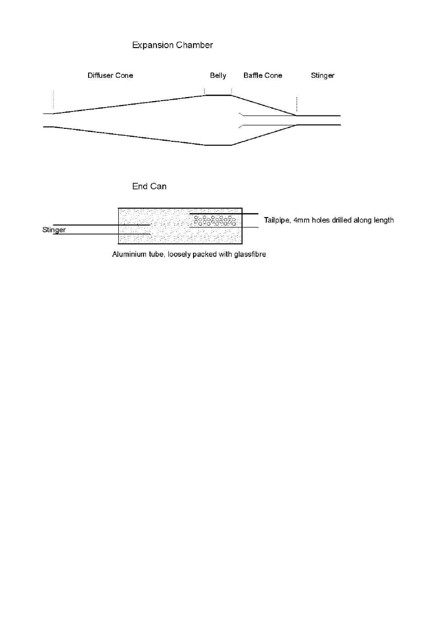
Exhaust
Exhaust header and diffuser cone have to be standard. To complete the expansion
chamber, forget the calculations. It is near impossible to correct for the small header
diameter, which coupled with the small chamber diameter (fixed by regulations),
variations in ignition timing and compression ratio all affect the exhaust gas
temperature and bugger up the calculations without an accurate measurement. Most of
the simple models use engine speed and port duration as a basis and some even have
9
BMEP correction, but these all make assumptions about the speed of sound in the gas
which is heavily temperature dependent, and the degree of taper in the header section is
critical (where the MZ pipe has zero).
Best to make up a few pipes (or borrow some) and dyno it - for a starting point roughly
you need about 2 to 4 inches of belly between the diffuser and baffle cone, with a 12
degree cone. There are as many variations in this as there are bikes - steeper cones,
shallower cones, shorter and much longer bellies ... you are heading for about 30 BHP at
8000 rpm with these class rules, but don’t aim for an absolute figure, find a pipe that
appears to give a good peak then dial in the jetting and timing to match it.
There is some good information in how to form cones in sheet steel in the A. Graham Bell
book (see refs) if you are any good at tin-bashing and welding. I have even tried hydro-
forming using a Karcher garden pressure washer – good for fancy shapes but not much
point with the restrictions we have in this class. The picture below shows my up-swept
pipe made in this manner.
Set the stinger (bleed tube from the expansion chamber) to start inside the chamber – up
to but no further than the start of the rear cone. This both improves the strength of the
return pulse and reduces the emitted sound level, by preserving pressure energy in the
chamber (courtesy 'Batwings' Hoyt McKagen). Flare the internal end of the stinger, and
you can drill a few 4mm holes down the side too, just to help the flow out of the chamber.
Then an end can is put on the outside end of the stinger to bring the noise level within
regulation. This can be home made or there are several off-the-shelf cans available.
10
Ignition
Ignition is best with a PVL Kart magneto - these are supplied anticlockwise for Kart
fitment so they need to be mounted with the stator plate reversed in this case, but check
when you buy it. The kit comprises a rotor and stator forming the generator, and a coil
containing some electronics – it produces a short, high energy spark. Just needs
mounting somewhere on the frame (the leads are not very long mind you) with an earth
connection to the engine.
I am working on an electronic timing variator for these, as they are fixed as standard,
normally set about 17 or 18 degrees BTDC (1.8 to 2.0 mm). Burwins and Holmshaw sell a
mounting plate for these to fit them to the cases, or one can be turned from a piece of ally
bar, or fabricated from plate cut to shape (tricky this way to get it to sit square and
central!) but there is a very small clearance rotor-to-stator and no margin for error.
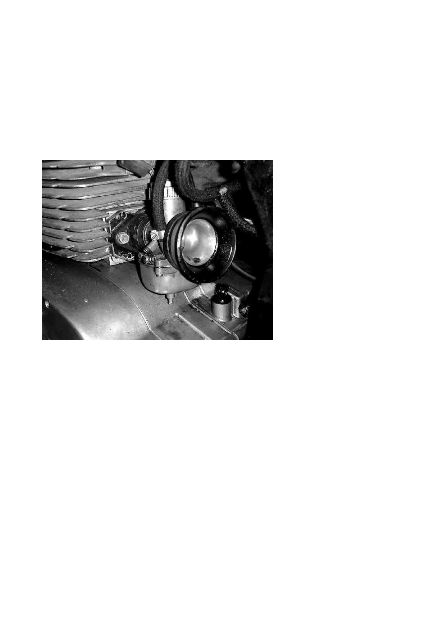
Carburettor
Carb gets bored out to max (normally 33mm without weakening the carb body). Some of
the older castings can be bored to 35mm, some of these show better power on the dyno
but not always as usable on the track. You need to drift out the brass spray baffle in the
carb throat in order to do the boring - remove the main jet and unscrew the needle jet
tube a couple of turns, tap it to start it moving, then unscrew the needle tube a bit more
and carry on gently tapping until you run out of thread on the needle tube. Then you
need a square ended drift to go in its place, that can be cocked slightly to one side against
the bottom of the baffle so you don’t damage the thread, and drift it the rest of the way
out.
Shape the baffle shoulder to give a smooth air path where it meets the floor of the throat,
because now you have machined into it and the shoulder will stick up. Put the baffle stub
11
back carefully, locating it pointing the right way in the splines and drift it back down
using a small tube that fits over and pushes on the shoulder.
The fuel passages to the float valve are a bit roughly made and fuel flow can be a
problem. The pipe connection needs opening up a little and the cross-drilling inside
might need aligning – you have to drill through the end of this passage and then plug it
up afterwards, but have a good close look and see if it needs it. The valve orifice itself
benefits from enlarging but be careful as the edge of the drilling forms the seat of the
valve and the seal needs to be checked afterwards.
I think there is work to be done on the fuel delivery/airflow curves on these carbs. There
is no air-bleed adjustment as they are 'primary choke' type carbs, and this means
adjustments have to be made to the height of the spray baffle and the root diameter of
the needle jet (top of the jet tube) which is complicated by the lack of different sizes
available, so the whole area of adjustment gets overlooked. Some good texts on this are
John Robinson, and A Graham Bell (see refs).
Dialling in the jetting ... no two ways about it, this takes time – read the books! The
carburation circuits are not ideal in the BVF and are even less suited to Reed Valve
modifications. There is no magic formula to determine the engine’s metering demads so
start with a big jet and work downwards for safety: if you run too lean ie with too small a
jet you may not even complete one lap! The only guide I can safely give is that 300 is very
big and 100 is very small. These sizes are the metering orifice diameter in hundredths of
a mm so 220 is 2.20mm, 195 is 1.95mm etc.
Frame
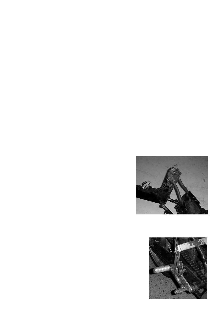
General aims: chop off anything that doesn't make it
go faster or stop quicker - the stand and footrest lugs
(saw through the main downtube section about 2
inches below the swingarm pivot – see photo), the
battery tray, the pump mounts etc. Chuck out the
airbox, sidepanels, oil tank, and mudguards (the
front might be useful if you keep the 18 inch wheels,
and the little plastic section of the rear is a useful
splash guard). Obviously the lights aren’t allowed,
and the horn is not much use so the entire wiring loom and all the bits & bobs can go.
Renew head race bearings (fit the sealed type) and swingarm bushes. Attend to engine
mounts (see below).
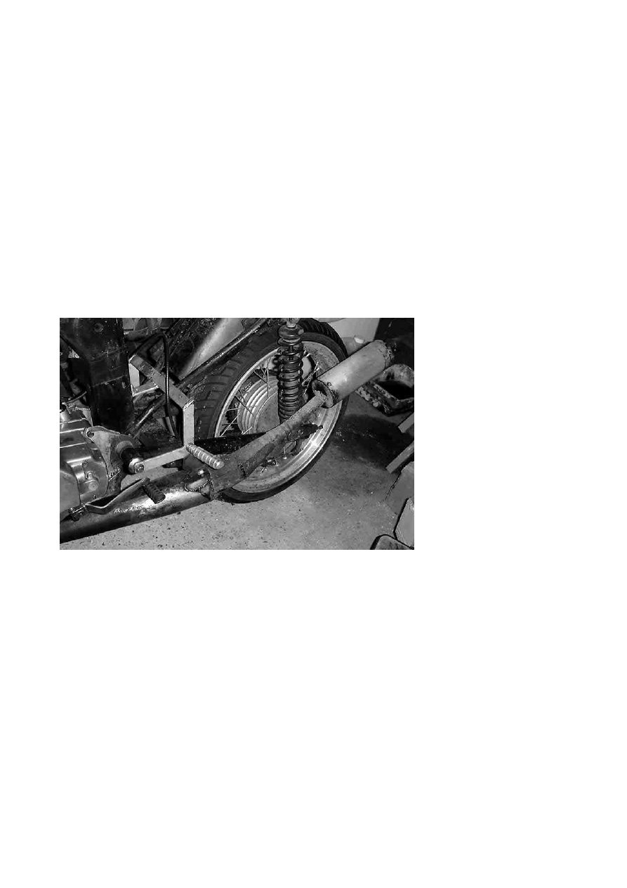
Footrests
Rearsets need making up or buying - Burwins and LeMoto
make a set which can be bought as individual parts, or a
complete kit with brackets and cable. Connecting the rear
brake appears to be the biggest problem but the TS rear
hub has an internal cable attachment which is very tidy. I
cheated and bought the Burwins footpegs and made my
own mounting bracket (photo, right) the advantage being
the cable is available as a spare part from them. Then all I
had to do was weld a threaded cable stop on to the torque
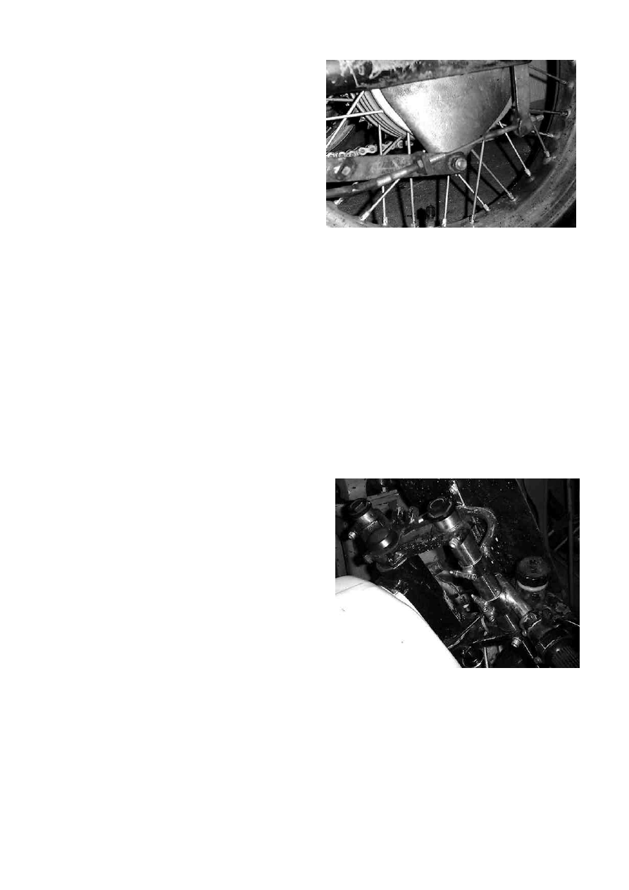
12
arm (photo,). The bracket can be made from
one-inch square tubing, or something
similar, just three pieces welded to form a
sort of 'C' section to mount across the rear
frame stays. This can be attached with
jubilee clips - remember that no welding is
allowed to the frame in current regulations
(2002). There is a 6mm stud in the main
downtube that can be used, where the
airbox used to go.
Engine Mounts
Replace rear engine mount inserts and check mount plates for cracks. These are a little
bit flimsy and tend to crack, so can be reinforced in a number of ways or stiffened ones
can be bought to fit.
Upper (cylinder head) mount needs modification to fit the shortened cylinder
arrangement: the original one works fine if one side is attached by a stout strap, and the
studs in the head are replaced by solid stand-offs. The position of the engine in the frame
(up or down) determined by this mount affects the drivetrain angle so pay attention to it!
Alternative arrangements for the upper mount include using a solid bar attached to the
frame stud, and rubber mounts in place of the cylinder head studs. Mine are Peugeot 505
exhaust mounts, which are cheap, quite hard and durable lasting most of a season.
Fork yokes and headstock, Forks, Rear shocks
Summary: shorten rear shocks by
unscrewing the top eye and threading down
the damper rod, then shorten the spring by
the same amount by cutting with an angle
grinder (make sure both springs are
identical); fit a bottom yoke in place of the
top yoke so the forks can be adjusted up and
down, as per photo below (drive out the
headstock tube and fit it upside down or it
will foul on the top bearing housing); rework
the fork damper valves as described (resize
rebound hole, clean up compression valve
housing).
Regarding steering geometry, you have to think carefully about what is going on here.
The MZ road settings are a bit spongy and unresponsive but can be sorted out with a
little work. Dropping the forks down the yokes (i) reduces rake angle and (ii) reduces
trail, both of which increase sensitivity, which is what you want but the reduction in trail
happens much faster than the rake change as the forks drop down which reduces
stability a lot. You need to find a balance that suits your riding style, body position,
weight etc by experiment, adjusting the position in the yokes by 5mm steps or so. A good
reference is John Bradley's 'The Racing Motorcycle' which looks in detail about chassis
tuning and other aspects of setting up a racing bike.

13
You will observe many different fork positions relative to yoke on other people's bikes,
but this is affected by (i) fork stanchion length if it has been modified and (ii) preload
spacers that some people use. Best measurement for comparison is the height to the
bottom of the headstock on a bike with exactly the same wheels and rear shocks as yours,
but if you measure their rears you can correct the front measurement for differences in
this.
Adjusting the rear shock length shifts the ride height, hence centre of gravity but also
alters rake & trail, so the front height has to be adjusted by a similar amount to give the
same geometry. It also affects the angle of the swingarm, and thus the angle in the drive
train between the front and rear sprockets which affects the 'anti-squat' action, ie
propensity to wheelie but it is not hugely sensitive to this because the power delivered is
not exactly massive. This is a big issue on Motocross bikes. When I shortened my MZ
rears by 25mm I noticed the difference at the start line (easier to keep the front down),
and some might argue the traction at the front is improved accelerating out of corners
but I don't think anyone would admit to noticing a reduction in rear traction, both of
which are theoretically happening when you change this drive angle.
Bear in mind that use of preload *only* shifts the ride height, it *does not* stiffen the
spring. You need to change the spring itself to change the spring rate. Preload spacers
can be used at the front to increase useful travel of the shock - the ride height changes
when these are used so the fork position in the yoke needs compensating for them to
correct the geometry. Different oil levels in the front changes the spring rate slightly due
to the pneumatic action of the air pocket in the fork - a higher oil level will give a
stronger spring action (pressure builds up quicker with compression).
I use 250ml per leg with standard length stanchions, no preload spacers, sidecar springs.
Works for my body weight. At the rear I have shortened the standard MZ shocks by
25mm and dropped the front from the standard position an additional 15mm to increase
sensitivity.
The fork damper design is a bit agricultural, to be polite. It works reasonably well with
SAE30 engine oil or EP80 gear oil (both of which are about the same viscosity) but it
tends to froth up. It can be improved if the 3mm bleed hole in the damper rod is welded
up and redrilled at 2mm – this stiffens the rebound damping to a level that works with
20 to 30 weight fork oil, preferable for its anti-froth properties. If the hole is much
smaller, I have found other problems with cavitation and poor oil flow.
The lower valve can stay standard with the above modification – again I have found
problems when the throttle plate holes are reduced. But the recess in the fork leg that
the valve lives in can be very roughly machined which makes the valve washer stick, so
take it apart and smooth out the ridges carefully with emery paper or a die-grinder. A
lathe would be the best way, but it only needs tidying, be careful not to make the throttle
plate a slack fit in the leg.
14
Wheels and tyres, Brakes
Summary: Braided steel brake
hose, racing pads, high spec fluid,
racing tyres, new wheel bearings.
Optional 17 inch wheels, giving
greater tyre choice inc. slicks &
wets, lighter handling & more
responsive.
Fitting front wheels: alignment of
the forks and headstock must be
carried out before the yoke and
wheel spindle pinch-bolts are
tightened, or mudguard and
forkbrace where fitted. It is
simple enough, but important to
do otherwise the fork action may
be slightly stiff: with the bottom
yoke pinch bolts tightened, and
the top yoke, headstock centre
nut, wheel spindle nut and
spindle pinch-bolt a little more than finger-tight, bounce the forks up and down a few
times to align the sliding parts. Tighten the top yoke pinch-bolts, headstock nut and
spindle nut in that order, and bounce it again. Then tighten the wheel spindle pinch bolt.
Check that all is sliding freely before tightening the mudguard or forkbrace. If not loosen
the spindle and yoke pinchbolts, bounce it a few more times and try again.
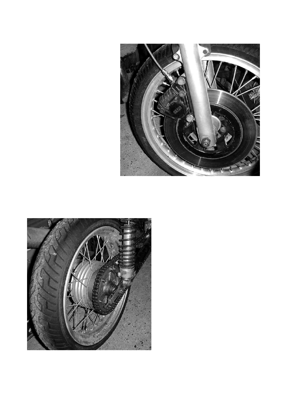
Rear sprocket carrier can be modified
for interchangeable sprockets, which is
useful for fine-tuning the gearing when
you are in close competition. The
standard 48 tooth rear is useable with 3
different fronts (say 17, 18 and 19 teeth
with 18 inch wheels) but the condition
needs to be checked carefully, the
original ones don’t tend to be very
round which makes the chain tension a
bit of a lottery. One of the best 100-
quids I spent was on the split sprocket
kit from Tony Holmshaw – see photo,
right – so you don’t need to remove the
rear wheel and carrier to dial-in the
gearing. Anything that contributes to a
hassle-free race meeting is good in my
book.
The recommended 17 inch rim sizes are
2.15 front (WM3) and 3.50 rear. These give the greatest range of tyre fitments, including
the ‘50’ profile slicks and wets. Alternately 1.85 front (WM2) and 3.00 rear work with
15
the Dunlop intermediates (KR364) but it is wise to check tyre availability and suitability
with a specialist. These low profile types are very sensitive to the rim width.
General preparation
Scrutineering is a bit like an MoT,
the bike is checked for compliance
with the regulations and for race-
worthiness – ie that the bike has
been carefully prepared for the
meeting. It helps alot if the
machine is clean as this is a good
sign that attention has been paid
to it since the last meeting and will
not raise doubt over your
commitment to the safety of
yourself and others.
Ensure after you have worked on
the bike all nuts and bolts etc are
secure. Do not over-tighten things
as you will strip the threads easily on the engine and wear them quickly elsewhere as on
a race bike they are undone and done up so often. Make sure NOTHING is touching the
wheels that shouldn’t be - ie the exhaust, caliper bolts etc. Especially in a "loaded
position".
Chain tension should be checked with weight on the suspension also. ACU regulation for
2002 requires a chainguard at the entry points to sprockets to prevent clothing etc
becoming entangled so a rear guard must be fabricated and fitted to the swingarm
covering the lower segment of the sprocket.
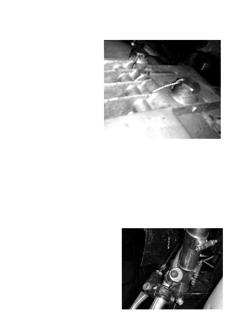
ACU regulations also require any oil-retaining plugs to be fixed with lockwire to prevent
spillage if they work loose. For the MZ this is the two plugs in the gearbox underside and
the filler bung (see photo). Breathers have to be routed to a catch-tank of a specified size
– technically this includes the hole in the gearbox oil filler bung and carburettor float
bowl breather on the MZ.
The throttle control must return to the
closed position when released, and an on/off
switch must be fitted to the handlebars
(not a ‘kill’ button with momentary action –
photo shows my left clipon, which has
both!).
Numbers must be displayed in the
designated colours, currently white
numbers on green backgrounds. One at the
front, one either side at the back. Burwins
do a nice matching set of clipons and front
number bracket, shown in these photos.

16
Information
Book References
A Graham Bell ‘Performance Tuning: Two Stroke’
John Robinson ‘Motorcycle Engine Tuning: Two Stroke’
Gordon Jennings: ‘Two Stroke Tuners Handbook’
G P Blair: ‘The Basic Design of Two Stroke Engines’
John Bradley: ‘The Racing Motorcycle’
Tony Foale: ‘Motorcycle Handling and Chassis Design – the Art and Science’
Suppliers
Dartford Karting - PVL Kart magneto, it is the 'Small Bore' model.
Tony Holmshaw motorcycles - full tuning range including pipes, reboring, crankshaft
rebuilds, port work, new and secondhand MZ parts, advice etc; specialities include
modified rear sprocket carrier and split sprockets
Burwins motorcycles - full range of tuning parts and services as above, new and
secondhand MZ parts, specialities inc clip-ons, rearsets, engine mounts
LeMoto - special chassis parts inc modified shocks, fork yokes, rearsets, seat units etc
Talon Engineering (Southampton) – alloy wheel rims, fancy stuff
Central Wheels (Birmingham) – all manner of wheel related stuff
Hagon (E London) – wheels, shock treatment.
Maxton – shock experts
Tony Hartlen: vintage and racing motorcycle engine machinist. 01483 202540 near
Guildford, Surrey
Alec Jay: wheel builder, vintage restoration. 01403 752774 near Horsham, W. Sussex

17
Table: Piston displacement
Crank degrees against mm ATDC
Angle Disp.
0
0.00
1
0.01
2
0.02
3
0.06
4
0.10
5
0.15
6
0.22
7
0.30
8
0.40
9
0.50
10
0.62
11
0.75
12
0.89
13
1.04
14
1.21
15
1.38
16
1.57
17
1.77
18
1.98
19
2.21
20
2.44
21
2.69
22
2.94
23
3.21
24
3.49
25
3.78
26
4.08
27
4.39
28
4.71
29
5.04
30
5.38
31
5.74
32
6.10
33
6.47
34
6.85
35
7.23
36
7.63
37
8.04
38
8.45
39
8.88
40
9.31
41
9.75
42
10.20
43
10.65
44
11.12
45
11.59
46
12.06
47
12.55
48
13.04
49
13.54
50
14.04
51
14.55
52
15.06
53
15.59
54
16.11
55
16.64
56
17.18
57
17.72
58
18.26
59
18.81
60
19.37
61
19.92
62
20.48
63
21.05
64
21.61
65
22.18
66
22.75
67
23.33
68
23.90
69
24.48
70
25.06
71
25.64
72
26.22
73
26.81
74
27.39
75
27.98
76
28.56
77
29.15
78
29.73
79
30.32
80
30.90
81
31.48
82
32.07
83
32.65
84
33.23
85
33.81
86
34.38
87
34.96
88
35.53
89
36.10
90
36.67
91
37.24
92
37.80
93
38.36
94
38.92
95
39.47
96
40.02
97
40.57
98
41.11
99
41.65
100
42.19
101
42.72
102
43.25
103
43.77
104
44.29
105
44.80
106
45.31
107
45.81
108
46.31
109
46.80
110
47.29
111
47.77
112
48.25
113
48.72
114
49.19
115
49.65
116
50.11
117
50.55
118
51.00
119
51.43
120
51.87
121
52.29
122
52.71
123
53.12
124
53.53
125
53.92
126
54.32
127
54.70
128
55.08
129
55.46
130
55.82
131
56.18
132
56.53
133
56.88
134
57.22
135
57.55
136
57.87
137
58.19
138
58.50
139
58.81
140
59.10
141
59.39
142
59.68
143
59.95
144
60.22
145
60.48
146
60.73
147
60.98
148
61.22
149
61.45
150
61.68
151
61.89
152
62.10
153
62.31
154
62.50
155
62.69
156
62.87
157
63.04
158
63.21
159
63.37
160
63.52
161
63.67
162
63.80
163
63.93
164
64.05
165
64.17
166
64.27
167
64.37
168
64.47
169
64.55
170
64.63
171
64.70
172
64.76
173
64.82
174
64.87
175
64.91
176
64.94
177
64.97
178
64.99
179
65.00
180
65.00

18
An interesting discussion on tyres and handling
A mailing-list posting (one of Michael Moore’s – see above):
Subject: MC-Chassis Re: Black rings
Dave w asked:
<<
a comparison to other cruisers whose equal front & rear sizes
made them "theoretically" unable to steer "on lean angle alone."
Is there anything to this, or is this a case of a motojournalist
knowing what he likes in a bike's handling but not why it handles
like that...
>>
The actual statement is far too general. There are all sorts of parameters
that determine both steering and tyre size effects on handling.
Cornering force on an upright tyre (as one tries for in a car) comes from
slip angle, i.e. we have to steer a little more than the path of a curve to
generate a force that pushes the vehicle towards the turn centre. So the
cornering force can be directly controlled by the driver, depending soley on
his steering input.
Bike steering is somewhat more complex. A tyre that is cambered in relation
to the road surface creates a cornering force due to what's known as
"camber-thrust" the mechanism for this is akin to a rolling cone which
tends to steer about it's apex. The cambered tyre is just like a slice of
a cone.
Now, obviously the cornering force so generated depends on lean angle and
tyre characteristics / sizes etc. At any given road speed this camber
thrust may be either
too little, too much or just right to provide the cornering force that the
rider wants. If it's just right then the rider need apply no steering angle
to the handlebars in order to corner as he wishes. However, if the camber
thrust is not exactly correct then he must apply either some negative or
positive steering angle to detract from or add to the cornering force. This
corrective steering angle generates this corrective force by slip angle as
with a car.
It is because much of the cornering force comes from camber thrust that
actual steering angles on a bike are much less than with a car.
Some bikes need little effort to go where we wish yet others seem to need
"holding down" to stay on line whereas some need "lifting up", this "feel"
is a direct result of how much and in which direction we need to apply
corrective slip angles to adjust for the difference between the camber
thrust generated and the cornering force required.
Just as with a car, we do not steer by the front wheels alone. Conventional
(non-RWS) cars must generate cornering force from the rear tyres also, thus
the rear must also have a slip angle, this is achieved by the car body
adopting a yaw attitude inward of the desired cornering path.
Likewise on a bike, if the camber thrust from the rear tyre doesn't balance
the required cornering force at the rear then the bike must adopt a yaw
attitude to correct the imbalance by adding or subtracting cornering force
by means of slip angle.
So to claim that equal size tyres are incapable of "steering by lean angle
alone" is quite obviously a gross over-simplification at best. There are
so many factors involved and NO BIKE steers by lean angle alone under ALL
cornering conditions. A wet road will affect camber thrust around the same

19
corner at a given speed, and so any corrective steering torque will also
depend on road conditions. This is just one reason, amongst others, that
gives a different "feel" to the bike when it's raining.
Tony Foale.
Acknowledgements
Tony Holmshaw: ‘what a nice man – and so reasonably priced’
Martin Baldwin & Mike Wright (Burwin Motorcycles) and of course Anne Baldwin
John Wood for the loan of pictures from his book ‘Villiers Singles Improvements
Handbook’, also some bright ideas in the making of my bikes and this booklet and an
interesting website
http://www.lortim.demon.co.uk
Michael Moore (Eurospares, San Francisco) fantastically interesting archive and contacts
website
http://www.eurospares.com
Some other interesting sites from interesting people:
http://www.22000rpm.com
http://home.mira.net/~iwd
http://www.freeyellow.com/members/batwings/best.html
http://www.ctv.es/USERS/softtech/motos/
Someone in Spain on
rec.motorcycles.racing
once helpfully pointed out that the MZ250
is locally known as ‘La Maceta’ which means Flower Pot. That makes us the Flower Pot
Men?
Wyszukiwarka
Podobne podstrony:
Katalog części MZ ES 250 0 250 1
MZ ETZ 250 Instrukcja Napraw PL
MZ ES 175 250 Instrukcja obsługi
Katalog części MZ ES 250 0 250 1
katalog czesci mz es 250 0 250 1
DANE TECHNICZNE MOTOCYKLA MZ ES 250
schemat silnika MZ ETZ 250 i 251
MZ ETZ 250 Instrukcja Napraw PL
MZ ES 175 250 Instrukcja obsługi
ARKUSZ PRZEGLĄDOWY MZ ETZ 250
MZ TZrokII cw1(1)
mz
Nowe prawo Praktyka z 23 grudnia 08 (nr 250)
250
250 751401 mlynarz
AP 250 Aerospatiale BAC Concorde
aerotrainI80 250
MZ IZ 3
więcej podobnych podstron