
Journal of ELECTRICAL ENGINEERING, VOL. 59, NO. 4, 2008, 195–202
A NEW TIME DOMAIN MODEL
FOR ELECTRIC ARC FURNACE
Rahmatollah Hooshmand
∗
— Mahdi Banejad
∗∗
— Mahdi Torabian Esfahani
∗
The electric arc furnace (EAF) behaves like a non-linear load that draws the attention of many researchers. At first in
this paper, the important time domain models of EAF are investigated. Then, an optimal time domain model for EAF is
proposed to describe the performance of the EAF for different operating situations. In this paper, after deriving a model
for EAF, its effects on the power system are studied by means of the PSCAD software. Several characteristics for different
operating conditions are then investigated to analyze the proposed method. In addition, for a time-variant and non-linear
load which generates voltage flicker and unbalanced voltage, the EAF are modelled. In order to study the effect of voltage
flicker on the systems with EAF, random and sinusoidal voltage flickers are considered. Also, in this paper, the effects of the
transformer of EAF and common inductance of the flexible cables are investigated. Finally, results of the simulation show
the validity of the proposed model of EAF model in this paper.
K e y w o r d s: electric arc furnace modelling, unbalanced voltage, flicker, electric arc
1 INTRODUCTION
The EAFs are time-variant and non-linear loads and
create the power quality problems such as unbalanced
voltages and currents, voltage flickers as well as odd and
even harmonics. These problems need to be rectified in
the EAF. Therefore, an optimal model is necessary to
tackle the problems. Also, the characteristic of the time
response of the EAF has an important role in the power
quality issues.
The dynamics characteristic of the electric furnace at
any instant is dependent on the conditions of the EAF at
that time and previous instants of time. Because, when
the arc is generated, a sudden change in electrons, ions
and temperature of gas due to a sudden change of the
electric current is not possible. As a result, the sudden
change of the current will not result in a sudden change of
the arc characteristic and this takes place slowly. In other
words, due to the effects of the current in the previous
instants of time on the present time, there is a hysteresis
phenomenon in the dynamic characteristic of the arc.
Thus, the time response of the EAF is influenced by the
length of arc, positions of electrodes and topology of the
external circuit.
The main issue is the modelling of the arc in the EAF
[1-14]. There are several methods used to describe the
electric arc. The balanced steady state equations are em-
ployed in [1, 2]. Some of the models are based on stochas-
tic characteristics of the EAF which are mainly suitable
for voltage flicker analysis [3, 4]. The differential equa-
tions based time domain methods are presented in [5, 6].
The methods described in [7, 8, 13, 14] to analyze the per-
formance of the EAF are based on the linerization meth-
ods and linearized approximation. Other methods such as
frequency response [7], V − I characteristic [7, 10] and
non-linear differential equations [11, 12] are employed to
analyze the behaviour of the EAF. In the following, the
advantages and disadvantages of the mentioned methods
are reviewed briefly.
The use of steady state equations is very useful in com-
putational work. Nevertheless, it considers only the bal-
anced situation of the three phase currents. In addition,
an approximated step model is used to model the wave-
form of the voltage-current characteristic (VIC) of the
EAF.
In the time domain analysis, the parameters are de-
termined based on the harmonic source voltages and the
unbalanced three phase currents. However, like the pre-
vious method, it uses an approximated step [5]. Another
method to analyze the arc model in the time domain is
based on the Cassi-Mayer equation [6]. In this method
Cassi and Mayer equations are employed for the low and
high current of the arc, respectively. In the method of lin-
earization and approximation of the arc voltage is deter-
mined based on the current of in the V −I characteristics
of the arc [2, 7].
Comparison the EAF model in the time domain and
frequency domain [9], shows that the modelling in the
time domain is more useful in studying the arc furnace
∗
Department of Electrical Engineering, University of Isfahan, Isfahan, Iran, hooshmand r@eng.ui.ac.ir, torabian m20@yahoo.com;
∗∗
Faculty of Electrical and Robotic Engineering, Shahrood University of Technology, Shahrood, Iran; m.banejad@shahroodut.ac.ir;
ISSN 1335-3632 c
° 2008 FEI STU

196
R. Hooshmand — M. Banejad — M. Torabian Esfahani: A NEW TIME DOMAIN MODEL FOR ELECTRIC ARC FURNACE
elements and EAF analysis. But, the frequency domain
models are more helpful for harmonic analysis of the ex-
ternal network. The external network is the model of a
linear system considered at each harmonic.
In the above explained methods, there are some re-
strictions such as initial conditions for the differential
equations, balanced situation of the three phase currents
and use of complicated mathematical equation for the
modelling of the arc model.
Regarding the mentioned limitations, this paper pro-
poses a new model for the EAF in the time domain. The
main feature of the proposed model is modelling of the ex-
plained method with a good approximation without need
of the initial conditions of the EAF. Also, the proposed
method can be used to describe different operating situa-
tion of the EAF and power system. Finally, the proposed
method presents an efficient model with a very good ap-
proximation for the VIC. In order to increase the accuracy
of the load model, random and sinusoidal noises are used
to establish a new model of the furnace load. Then, un-
balanced conditions of the currents and voltages and the
effects of the furnace load and voltage flicker are stud-
ied in the new model. Also, in this paper the effect of
voltage flicker on the voltage arc furnace is analyzed di-
rectly, in the forms of both random and sinusoidal noises
in the frequency range of human vision (between 4-14
Hz). In addition, regarding the effects of the transformer
of the EAF,and the resistance of the flexible cables, it
is necessary to find an actual model in the time domain
to describe adequately the EAF performance for different
operating conditions.
2 LOAD MODELLING OF EAF
In this section, the equations of EAF for three main
models are studied based on VIC of the arc. Then, the
proposed model is presented to describe the performance
of the EAF.
1 – Hyperbolic Model
In this model the VIC of the electric EAF is considered
in the form V = V (I) as
V (I) =
·
V
T
+
C
i,d
D
i,d
+ |I|
¸
signum(I)
(1)
where I and V are the arc current and voltage of a given
phase, respectively. In addition, V
T
is the magnitude of
the voltage threshold to which the voltage approaches as
the current increases. This voltage is dependent on the
arc length. Constants C
i,d
and D
i,d
are corresponding
to the arc power and arc current respectively, and re-
garding the sign of the derivative of the arc current, they
can take different values. Since (1) is similar to the hy-
perbolic function, it is named a hyperbolic model. There
are different paths to increase or reduce the current. The
first describes the increasing current I(t), and the sec-
ond the decreasing current (d). Thus, constants C
i,d
and
D
i,d
are distinguished. The constants for the first path
are C
i
and D
i
and constants of the second path are C
d
and D
d
.
2 – Complete Exponential Model
The VIC of the arc in this model, is approximated by
an exponential function as follows
V (I) = V
T
(1 − e
−|I|/I
0
)signum(I)
(2)
In the equation describing this model, a current constant
(I
0
) is employed to model the steepness of positive and
negative currents, and an exponential function is used to
describe the VIC of the arc. This model can be employed
in optimization issue and reliability of the EAF.
3 – Exponential-hyperbolic Model
(Proposed Model)
In the proposed model, the positive current branch of
an antisymmetric VIC of the electric arc is described as
V (I) =
V
T
+
C
D+I
dI
dt
> 0, I > 0
V
T
(1 − e
−I/I
0
)
dI
dt
< 0, I > 0
(3)
In (3), I
0
is a current steepness constant. As shown in
(3), regarding the hysteresis property of the arc, there
are two cases for the positive current. In order to increase
and decrease the current of the EAF, the hyperbolic equa-
tion and exponential-hyperbolic form of the equation are
utilized, respectively. The proposed method describes the
EAF behaviour in time domain using differential equa-
tion [6, 9]. In addition, it is able to analyze the behaviour
of the EAF in the frequency domain without solving com-
plicated differential equations. In addition, the proposed
method can describe different operating conditions of the
EAF such as initial melting (scrap stage), mild melting
(platting stage) and refinement of the EAF. The results
are in agreement with actual situations of the EAF in the
steel industries.
3 ANALYSIS OF DIFFERENT OPERATING
CONDITIONS USING PROPOSED
EXPONENTIAL–HYPERBOLIC
MODEL FOR ELECTRIC ARC
In this section, different operating conditions for the
EAG are investigated. In order to study the effect of un-
balanced situation on the proposed exponential-hyperbo-
lic model of load of the EAF, different values for the volt-
age V
T
in (3) for different phases are chosen. In addition,
different values of V
T
are considered for positive and neg-
ative parts of each phase current to study the effect of
even harmonics which are generated in the early stage of
charging the furnace.
Journal of ELECTRICAL ENGINEERING 59, NO. 4, 2008
197
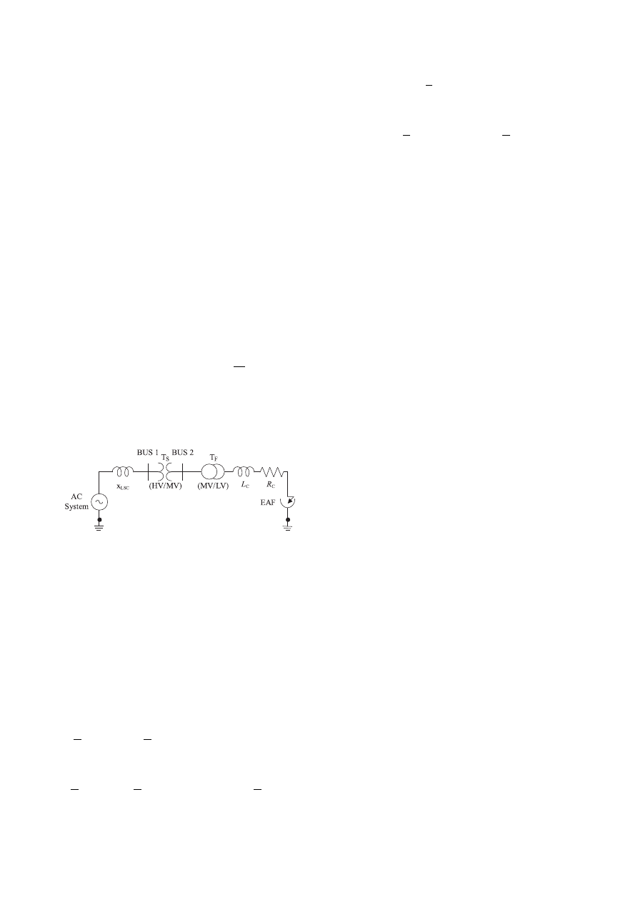
3.1 Power System with Actual Model of EAF
The electric diagram of a source supplying an elec-
tric EAF is illustrated in Fig. 1. In this figure, Bus 1
is the point of common coupling (PCC) which is the
supplying bus of the transformer of the EAF. In order
to change the active input power of the arc furnace, a
furnace transformer, T
F
, (MV/LV) is used. This trans-
former is equipped with a tap changer located at the sec-
ondary winding to change the voltage of the furnace. The
EAF is also connected to the point of common coupling,
PCC, through the substation. In this figure, X
C
and R
C
are the reactance and resistance of the connecting line and
between the furnace electrodes. Also, X
L,sc
is the short
circuit reactance at bus PCC. As can be seen in this fig-
ure, the resistance and inductance of the cables are also
considered in the modelling. This leads to the point that
the proposed method has very good agreement with the
real situation of the EAF of the steel industry. There-
fore, the actual model of electric arc is used in the power
system that can be described as
F (I) = V (I) + R
c
I + L
c
dI
dt
(4)
where F (I) stands for VIC of the arc in the actual sit-
uation of the power system and V (I) is related to (1).
Also, L
c
and R
c
shown in Fig. 1.
Fig. 1. Circuit diagram of an electric arc furnace connected to the
rest of power system
3.2 Reactive Power Analysis in a Power System
with EAF
As mentioned previously, the EAF’s are non-linear and
time-variant loads. In the EAF’s, the rate of variations
of the reactive power is high. Thus, it is necessary to
measure the value of the reactive power accurately. In
this paper, the reactive power at each buses of Fig.1 is
computed by an averaging method in the half period as
[10]
Q =
2
T
t
Z
t−T /2
V (τ −
T
4
) I(τ ) dτ
=
2
T
t
Z
◦
V (τ −
T
4
) I(τ ) dτ −
t−T /2
Z
◦
V (τ −
T
4
) I(τ ) dτ
(5)
If the value of V (t −
T
4
) · I(t) is replaced by F (t) in (5),
then we have:
Q =
2
T
t
Z
◦
µ
F (τ ) − F (τ −
T
2
)
dτ
(6)
This equation is used later to find the values of the reac-
tive power of the EAF.
4 EFFECT OF VOLTAGE
FLICKER IN PROPOSED MODEL
To study the effect of voltage flicker on the systems
with electric EAF, the time-variant form of V − t is con-
sidered. In this section, the effects of two types of flicker
on the dynamic characteristic of the EAF are studied. In
the first type, the voltage will be considered in the form of
a sinusoidal voltage flicker. In the second type, this volt-
age will be a random voltage flicker in the frequency range
of the human vision (between 4-14 Hz). In the following,
the two types of voltage flicker are considered.
4.1 V
T
with Sinusoidal Waveform
In this case the voltage V
at
is considered to be a
sinusoidal with the same frequency as the frequency of
flickering (in the range of 4-14 Hz).
V
T 1
= V
T 01
(1 + k
1
. sin ω
f
t)
V
T 2
= V
T 02
(1 + k
2
. sin ω
f
t)
V
T 3
= V
T 03
(1 + k
3
. sin ω
f
t)
(7)
Where V
T (j=1,2,3)
are three phase voltages of the furnace
load, V
T 0(j=1,2,3)
are constant values of the voltages if no
flickering would occur, ω
f
is the flicker angular frequency
and k
(j=1,2,3)
are the flickers ”amplitudes” for different
phases.
4.2 V
T
with Random Variations
In this part, the voltage V
T
is chosen such that it varies
randomly. In this regard, the voltage V
T
is modulated
with a random signal in the different phases. This signal
has the mean of zero with the frequency spectrum in the
range of 4-14 Hz. Thus, in this case the voltage V
T
for
different phases can be written as
V
T 1
= V
T 01
+ k
1
N
1
(t)
V
T 2
= V
T 02
+ k
2
N
2
(t)
V
T 3
= V
T 03
+ k
3
N
3
(t)
(8)
where N
(j=1,2,3)
(t) is a band limited white noise with zero
mean and a variance of 1. Also, the modulation index and
variance of the random signal are labelled by k
(j=1,2,3)
(t)
and k
j
N
j
(t), respectively. It should be noted that the
flicker intensity can be changed with k
j
.
198
R. Hooshmand — M. Banejad — M. Torabian Esfahani: A NEW TIME DOMAIN MODEL FOR ELECTRIC ARC FURNACE
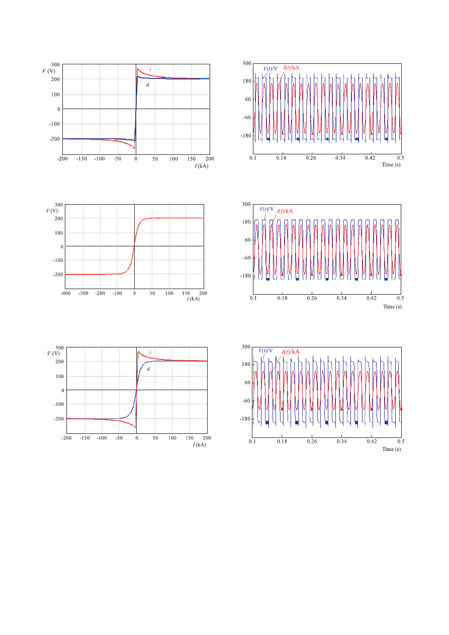
Fig. 2. The VIC of the arc the in hyperbolic model, increasing (i)
and decreasing (d) currents paths
Fig. 3. Waveforms of the arc voltage and current in the hyperbolic
model
Fig. 4. The VIC of the arc the in the exponential model increasing
and decreasing currents paths are identical
Fig. 5. Waveforms of the arc voltage and current in the exponential
model
Fig. 6. The VIC of the arc in the proposed exponential-hyperbolic
model, increasing (i) and decreasing (d) currents paths
Fig. 7. Waveforms of the arc voltage and current in the proposed
exponential-hyperbolic model
5 MODELLING AND SIMULATION OF EAF
5.1 Comparison of Different Models of Furnace
Load
In order to compare the proposed exponential-hyper-
bol-ic model with other models, firstly the results of sim-
ulations hyperbolic load model are presented. In Model
1, the parameters of arc characteristics are considered to
be: V
T
= 200 V, C
i
= 190000 W, C
d
= 39000 W and
D
i
= D
d
= 5000 A. The values in (9) are chosen with re-
gard to a specific EAF [11]. For particular values of these
parameters, the VIC of the EAF is shown in Fig. 2, and
the waveforms of the current and voltage of the arc are
shown in Fig. 3.
5.2 Analysis of Simulation Results for Proposed
Exponential-hyperbolic Method
In this part, the proposed exponential-hyperbolic
method is simulated based on the combination of (9) and
Journal of ELECTRICAL ENGINEERING 59, NO. 4, 2008
199
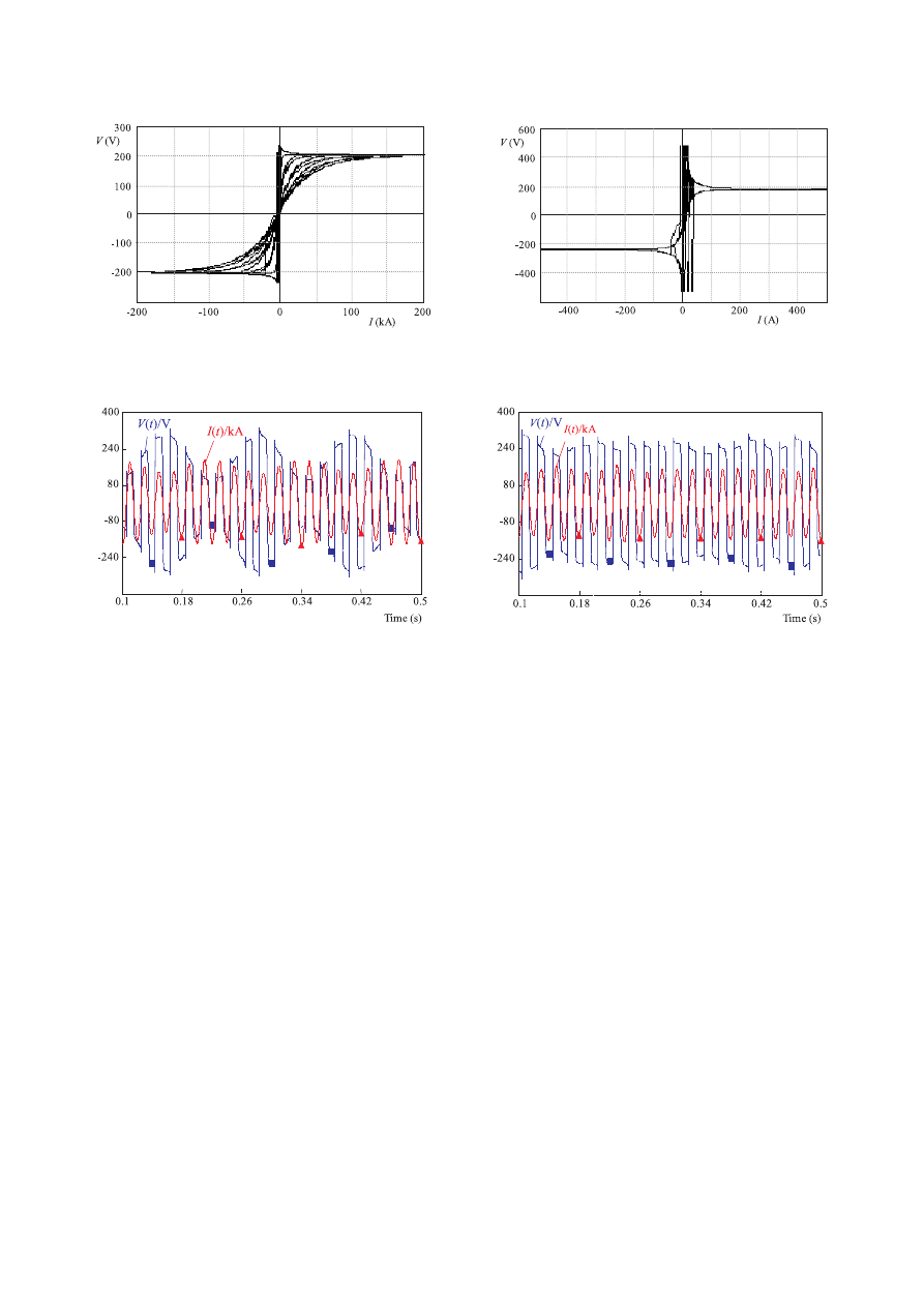
Fig. 8. The VIC of the arc in the refining stage (or melting down
process) stage in the proposed exponential-hyperbolic model
Fig. 9. The VIC of the arc in the scrap stage (or melting process)
in the proposed exponential-hyperbolic model
Fig. 10. Waveform of the arc voltage and current in the situation
of the sinusoidal flicker
Fig. 11. Waveform of the arc voltage and current in the situation
of random flicker
(10). The derived VIC of the arc is shown in Fig. 6. At the
points of this characteristic where the length of the arc is
not changed with time, it is assumed that this character-
istic constant (at the refining process). In this situation,
the EAF does not generate any flicker at PCC and it pro-
duces only odd harmonics in voltage and current; because
the VIC has a symmetric characteristics. This situation
explains the actual performance of the EAF at the plat-
ing period. In this period, the level of melting material is
nearly constant and the melting is distributed uniformly
in the furnace. Figure 7 shows the waveform of volt-
age and current for the proposed exponential-hyperbolic
model of the EAF. The results indicate that if the furnace
load does not produce any flicker, then the arc voltage,
current, and voltage and current of the primary side of
PCC oscillate similarly. When the EAF is in the melting
process (or scarp stage), the VIC of the arc is in the form
of Fig. 8. Finally, for the refining stage (melting down
stage) of the arc material, the VIC of the furnace is given
in Fig. 9. It should be noted that the parameters in this
section are obtained using curve fitting.
5.3. Analysis of Voltage Flicker
5.3.1 S i n u s o i d a l F l i c k e r
Regarding (7), the simulation of sinusoidal voltage
flicker is performed in this section and the used values
are: V
T 01
= V
T 02
= V
T 03
= 200 V, k
1
= k
2
= k
3
= 0.5
and ω
f
= 50 rad/s.
Results of simulation are obtained using the above val-
ues. The arc voltage and current as well as arc conduc-
tance are plotted in Fig. 10.
The results of the simulation show that if the furnace
load generates sinusoidal flicker, the arc voltage and cur-
rent, are varied sinusoidally with the flicker frequency.
5.3.2 Random Flicker
In this part, the simulation of the voltage flicker using
the random voltage is performed based on (8). The values
used in (8) are chosen as: V
T 01
= V
T 02
= V
T 03
= 200 V,
k
1
= k
2
= k
3
= 1.
Also,N
1
(t), N
2
(t) and N
3
(t) in this equation are three
white noise voltages with zero mean and variance of 1 in
the limited band (between 4-14Hz).
The waveforms of the voltage and current of the arc
are shown in Fig. 11. Similar to the previous part, when
the random flicker is applied, the load specifications of
EAF are varied randomly. Thus, voltage, current and the
three phase current of the primary side of the PCC bus
are changed randomly. In the other words, in this case,
furnace load flicker leads to a little variation in the voltage
of the bus supplying the EAF.
200
R. Hooshmand — M. Banejad — M. Torabian Esfahani: A NEW TIME DOMAIN MODEL FOR ELECTRIC ARC FURNACE
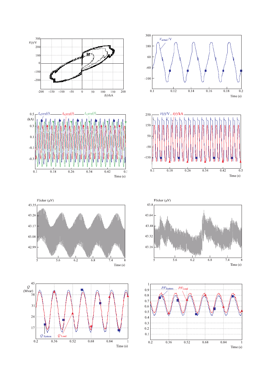
Fig. 12. The VIC of the arc in the actual situation
Fig. 13. Waveform of the voltage of the EAF in the actual situation
Fig. 14. Waveform of the three phase current at the primary side
of PCC bus in the unbalanced situation with the different three
phase voltages in the proposed exponential-hyperbolic model
Fig. 15. Waveforms of the arc voltage and current in the case
of even harmonics generation with different voltages V
T
of in the
proposed model of variations of the sinusoidal flicker
Fig. 16. The generated voltage flicker in the sinusoidal flicker
situation at bus PCC
Fig. 17. The generated voltage flicker in the sinusoidal flicker
situation at bus PCC
Fig. 18. The variation of the reactive power of the EAF and power
system the sinusoidal flicker situation
Fig. 19. The variation of the power factor of the EAF and power
system the sinusoidal flicker situation

Journal of ELECTRICAL ENGINEERING 59, NO. 4, 2008
201
Table 1. Harmonic magnitudes for different models of furnace load in the plate stage (in Volts)
Harmonic →
H
1
H
3
H
5
H
7
H
9
H
11
H
13
↓ Model
Hyperblic
256.38
87.39
54.25
40.58
33.48
29.46
26.28
Exponential
253.78
82.37
47.02
31.53
32.21
17.76
14.36
Proposed model
255.42
58.14
50.84
32.21
28.39
23.85
21.88
Table 2. Harmonic magnitude comparison between different operating conditions with proposed model (in Volt)
Harmonic →
H
1
H
2
H
3
H
4
H
5
H
6
H
7
H
8
H
9
H
10
H
11
H
12
H
13
↓ Model
Balanced
255.42
-
58.14
-
50.84
-
32.21
-
28.39
-
23.85
-
21.88
Unbalanced
223.29 13.723 73.63 13.65 42.90 13.38 29.43 13.35 21.93 13.09 17.38 13.11
14.18
Flicker:
Sinusoidal
149.23
14.1
53.62
6.40
28.08
0.82
24.64
4.82
15.82
3.03
16.59
2.92
13.623
Random
243.89
12.99
82.02
6.55
48.89
8.71
34.82
6.70
27.35
8.42
22.94
6.87
19.751
5.4 Results of Actual Model Analysis
Regarding Fig. 1, and considering the values of (4),
the VIC of the EAF is shown in Fig. 12. The voltage
waveform of the EFA is also shown in Fig. 13, which has
a good agreement with the actual case: X
lsc
= 9.4245 Ω,
X
c
= 2.356 mΩ, R
c
= 0.4 mΩ, f
sys
= 50 Hz.
5.5 Analysis of Simulation Results for Unbal-
anced Three Phase Furnace Load
One of the operating conditions of the EAF is perfor-
mance of the EAF in the unbalance load condition which
in most cases happens in the initial working condition
(scrap melting) of the EAF. In order to study the unbal-
anced situation in the proposed exponential-hyperbolic
model, the voltage V
at
in different phases are chosen as:
V
T a
= 200 V, V
T b
= 350 V and V
T c
= 450 V.
The waveforms of the three phase currents at the pri-
mary side are determined using the values given in (10).
These currents are shown in Fig. 14. Also in order to show
the even harmonics and asymmetry of the arc, the volt-
age V
T
for positive and negative current respectively was
considered as: V
T 1
= 200 V, V
T 2
= 175 V. With these
values, the waveform of the arc voltage and current are
shown in Fig. 15.
Results of Electric Power Analysis: The sinusoidal
voltage flicker and the proposed method in reactive power
measurement are employed to determine the reactive
power and power factor of the EAF. The, the variation
of the reactive power and power factor of the EAF are
shown in Fig. 18 and 19.
5.6. Harmonic Analysis for Different Models
In this part, the harmonic analysis for the different
models of the EAF is performed. In addition, the effects of
furnace load on voltage harmonics are investigated based
on the proposed exponential-hyperbolic model. In this re-
gard, Table (1) shows the generated voltage harmonics
in the situation of plating stage for the different mod-
els: hyperbolic, exponential and proposed exponential-
hyperbolic model. Since the odd symmetry is present in
the models, there are no even harmonics in the arc volt-
age.
Also, the voltage harmonics of the EAF for different
operating situation are shown in Table (2). As can be
seen in this table, because of lack of odd symmetry in
the electric arc, the even harmonics are present in the arc
voltage. As a result, these even harmonics are injected
to the power system. Moreover, when there is a voltage
flicker, the harmonics of the electric arc voltage can be
seen in this table. It should be noted that the magnitude
amount of harmonics depends on the intensity and type
of the flicker.
6 CONCLUSIONS
In this paper, at first, the existing hyperbolic and
exponential models for EAF are studied. Then, a new
model named exponential-hyperbolic model is proposed.
The new model has no limitation of the previous models.
The new model also, does not require any initial condi-
tions or special requirement for modelling. The model is
also able to describe the most of the specifications of the
EAF.
In this paper, a three phase structure of the electric
EAF is also proposed which includes the power quality
aspects such as: voltage and current unbalanced situation,
voltage flicker. Also, to analyze the effect of voltage flicker
on the voltage arc furnace, the voltage flicker is considered
in two forms of the random and sinusoidal noises in the
frequency range of the human vision (between 4-14 Hz).

202
R. Hooshmand — M. Banejad — M. Torabian Esfahani: A NEW TIME DOMAIN MODEL FOR ELECTRIC ARC FURNACE
The results of the simulation and comparing with existing
models show the advantages of the proposed method in
modelling of the EAF.
References
[1] MAYORDOMO—J. G.—BEITES, L. F.—ASENSI—R.—IZZ-
EDDINE, M. : A New Frequency Domain Arc Furnace Model
for Iterative Harmonic Analysis, IEEE Transactions on Power
Delivery 12 No. 4 (1997), 1771–1778.
[2] BEITES, L. F.—MAYORDOMO, J. G.—HERNANDES, A.—
ASENSI, R. : Harmonics, Inter Harmonic, Unbalances of Arc
Furnaces: A New Frequency Domain Approach, IEEE Transac-
tions on Power Delivery 16 No. 4 (2001), 661–668.
[3] FENGHUA, W.—ZHIJIAN, J. : Application of Extended Kal-
man Filter to the modelling of Electric Arc Furnace for Power
Quality Issues, IEEE Transactions on Power Delivery 10 No. 4
(2005), 991–996.
[4] PAK, L. F.—DINAVAHI, V. : Real-Time Digital Time-Varying
Harmonic modelling and Simulation Techniques, IEEE Transac-
tions on Power Delivery 22 No. 2 (2007), 1218-1227.
[5] BELLIDO, R. C.—GOMEZ, T. : Identification and modelling of
a Three Phase Arc Furnace for voltage Disturbance Simulation,
IEEE Transactions on Power Delivery 12 No. 4 (Sept 1997),
8885-8977.
[6] MOKHTARI—H.—HEJRI, M. : A New Three Phase Time-Do-
main Model for Electric Arc Furnaces Using MATLAB, Trans-
mission and Distribution Conference and Exhibition 2002: Asia
Pacific. IEEE/PES 3 (6-10 October 2002), 2078-2083.
[7] ZHENG, T.—MAKRAM, E. B.—GIRGIS, A. : Effect of Differ-
ent Arc furnace Model on Voltage Distortion, IEEE Conference
on Harmonics and Quality of power, 1079–1085. 14-18 Oct 1998.
[8] ANXO, M.—ALONSO, P. O.—PEREZ, M. :
An Improved
Time Domain Arc Furnace Model for Harmonic Analysis, IEEE
Transactions on Power Delivery 9 No. 1 (2004), 367–373.
[9] TING, W.—WENNAM, S.—YAO, Z. : A New Frequency Do-
main for the Harmonic Analysis of Power System with Arc Fur-
nace, IEEE, Conference, APSCOM-97, Hong Kong, 552–555,
1997.
[10] MONTANARI, G. C.—LOGGINI, M.—CAVALLINI, A. : Arc
Furnace Model for the Study of Flicker Compensation in Elec-
trical Network, IEEE Transactions on Power Delivery 9 No. 4
(1994), 2026–206.
[11] SCHAU, H.—STADE, D. : Mathematical modelling of Three
Phase Arc Furnacess, Proc. IEEE International Conference
Harmonics Power System, Bologna (21-23 September, 1994),
422-428.
[12] PETERSEN, H. M.—KOCH, R. G.—SWART, P. H.—HEER-
DEN, R. : modelling Arc Furnace Flicker Investigating Compen-
sation Techniques, International Conference on Industry Appli-
cations Conference, 1995. Thirtieth IAS Annual Meeting, IAS
’95, pp. 1733-1740, 8-12 October 1995.
[13] VARADAN, S.—MAKRAM, E. B.—GIRGIS, A. A. : A New
Time-Domain Model Voltage source for An Arc Furnace Us-
ing EMTP, IEEE Transactions on Power Delivery 11 No. 3,
1685–1996.
[14] ZHENG, T.—MAKRAM, E. B. :
An Adaptive Arc Furnace
Model, IEEE Transactions on Power Delivery 15 No. 3 (2000),
931-939.
[15] VAS, P. : The UIE Flickermeter Demystified, Hewlett-Packard’s
Power Products Division,
http://www.ce-mag.com/archive/1999/mayjune/McKim.html,
1997.
Received 20 March 2007
Rahmatollah Hooshmand was born in Isfahan, Iran in
1966. He received the BEng degree from Ferdowsi Mashhad
University, Iran in 1989, the MSc degree from Tehran Univer-
sity, Iran in 1990 and the PhD degree from Tarbiat Modarres
University, Iran in 1995 all in Electrical Engineering. His main
research interests are modelling of power systems and distri-
bution electricity Networks He is now the associate professor
of Department of Electrical Engineering at University of Isfa-
han.
Mahdi Banejad was born in Mashhad, Iran in 1966. He
received the BEng degree from Ferdowsi Mashhad University,
Iran in 1989, the MSc degree from Tarbiat Modarres Univer-
sity, Iran in 1994 and the PhD degree from Queensland Uni-
versity of Technology, Australia in 2004 all in Electrical En-
gineering. He was the manager of the Section of the Relation
between University and Industry of Shahrood University of
Technology in 2006-2008. His main research interests are load
modelling, power system dynamics and distributed generation.
He is now the assistant professor in Faculty of Electrical and
Robotic Engineering at Shahrood University of Technology.
Mahdi Torabian Esfahani was born in Isfahan, Iran in
1982. He received the BEng degree from Islamic Azad Uni-
versity Branch Najaf-abad, Iran in 2005 and the MSc degrees
from Islamic Azad University Branch Najaf-abad, Iran in 2007
all in Electrical Engineering.
E X P O R T
-
I M P O R T
of periodical s and of non-periodic ally
printed matters
, book s and CD - ROM s
Krupinská 4 PO BOX 152, 852 99 Bratislava 5,Slovakia
tel.: ++ 421 2 638 39 472-3, fax.: ++ 421 2 63 839 485
e-
mail: gtg@internet.sk, http://www.slovart-gtg.sk
s.r.o.
GmbH
E X P O R T - I M P O R T
G.T.G.
SLOVART
s.r.o.
GmbH
E X P O R T - I M P O R T
G.T.G.
SLOVART
Wyszukiwarka
Podobne podstrony:
Noise propagation path identification of variable speed drive in time domain via common mode test mo
Jacob Benesty, Jingdong Chen Optimal Time Domain Noise Reduction Filters
58 829 845 A New Model for Fatique Failure due to Carbide Clusters
Model du Ponta new, studia, finanse przedsiębiorstwa
Michael McMullen Astrology as a New Model of Reality
Network Virus Propagation Model Based on Effects of Removing Time and User Vigilance
Shan A Model of Wavefunction Collapse in Discrete Space Time
A Model for Detecting the Existence of Unknown Computer Viruses in Real Time
extrema ratio new Model (1)
1999 Taking Time A Tale of The Very New Superboy
Heron, Shapira (2003) Time to log of New diagnostic criteria for problematic Internet use
Comments on a paper by Voas, Payne & Cohen%3A �%80%9CA model for detecting the existence of software
R 6 1 Obiektowy model zapytan
model relacyjny
Prezentacja KST 2007 new
więcej podobnych podstron