
Initial Print Date: 01/09
Table of Contents
Subject
Page
Inputs/outputs, ULF- SBX High Interface Box . . . . . . . . . . . . . . . . . . . . . .4
ULF- SBX High Interface Box Circuit Diagram . . . . . . . . . . . . . . . . . . .6
Smartphone Integration Option Circuit Diagram . . . . . . . . . . . . . . . . .8
Input/outputs, Telematics Control Unit . . . . . . . . . . . . . . . . . . . . . . . . . . .10
Telematics Control Unit (TCU) Circuit Diagram . . . . . . . . . . . . . . . . .12
Bluetooth Pairing (pairing wizard) . . . . . . . . . . . . . . . . . . . . . . . . . . . . . . . .15
Phonebook Contacts . . . . . . . . . . . . . . . . . . . . . . . . . . . . . . . . . . . . . . . .17
Call Register (Dialled numbers, missed calls) . . . . . . . . . . . . . . . . . . .18
Convenience Plan (Optional) . . . . . . . . . . . . . . . . . . . . . . . . . . . . . .21
Smartphone Integration . . . . . . . . . . . . . . . . . . . . . . . . . . . . . . . . . . . . . .22
Components and Installation Locations . . . . . . . . . . . . . . . . . . . . . . . . . .23
ULF-SBX-H Interface Box . . . . . . . . . . . . . . . . . . . . . . . . . . . . . . . . . . . .24
Telematics Control Unit (TCU) . . . . . . . . . . . . . . . . . . . . . . . . . . . . . . .25
Location of ULF-SBX/ULF-SBX-H and TCU . . . . . . . . . . . . . . . .26
Location of USB Hub . . . . . . . . . . . . . . . . . . . . . . . . . . . . . . . . . . . . .28
USB Base Plate/snap-in Adapter . . . . . . . . . . . . . . . . . . . . . . . . . . . . .28
Telephone Antenna System . . . . . . . . . . . . . . . . . . . . . . . . . . . . . . . . . . . .29
Emergency-call GSM antenna . . . . . . . . . . . . . . . . . . . . . . . . . . . . . . . .29
F01 Telephone System
Revision Date:

2
F01 Telephone System
Telephone System
Model: F01/F02
Production: From Start of Production
After completion of this module you will be able to:
• Describe the telephone system of the F01/F02
• Describe the new functions of the telephone system of the F01/F02
• Identify the components of the telephone system of the F01/F02
The Telematics Control Unit (TCU) and the interface box ‘High’ (ULF-SBX-H) control
units are connected to the MOST bus. TCU and interface box ‘High’ may both be fitted
in the vehicle for certain equipment options. In this case, the telephone function is always
implemented in the TCU.
The head unit transmits the audio signal in analog form to the HiFi amplifier and the
amplifier distributes the audio output to the loudspeakers in the car.
The HiFi system is fitted as standard in the F01/F02.
If the “Top HiFi system” is installed in the car, the audio signal is transmitted digitally on
the MOST bus to the HiFi amplifier and the amplifier distributes this signal to all the
loudspeakers.
Audio playback of the call recipient is via the front right, front left and center loudspeak-
ers.
For the sake of clarity the various individual loudspeakers are not shown in the schematic
circuit diagrams.
The Telematics Control Unit (TCU) used in the F01/F02 is similar to one used in the
E70.
The pairing wizard is again integrated in the F01/F02 to assist the customer in pairing
the mobile phone.
Note: The specified range of functions will only be achieved with Bluetooth-
enabled mobile phones recommended by BMW. See a list of compatible
phones at www.wireless4bmw.com.
3
F01 Telephone System
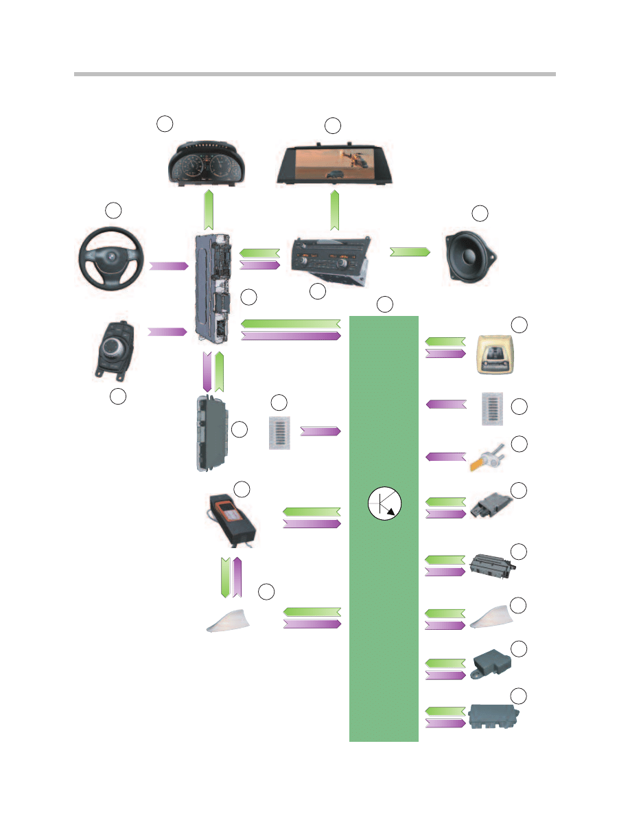
System Overview
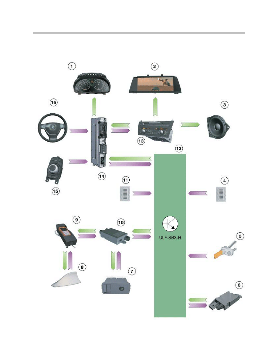
Inputs/outputs, ULF- SBX High Interface Box
4
F01 Telephone System

Optional extras “USB/Audio interface” and “Smartphone Integration” require the installa-
tion of the ULF-SBX-High Interface box.
The USB hub is installed only if the car is ordered with the “Smartphone Integration”
optional extra.
The mobile phone and the interface communicate via the Bluetooth antenna.
Voice output by the telephone system is via the vehicle’s front right, front left and center
loudspeakers. Volume can be adjusted by means of the multifunction steering wheel and
the CIC. Speed-related volume control is also active.
Although both the ULF-SBX-H and the TCU may be fitted in a vehicle at the same time,
the TCU always provides the telephone functions. In this case the telephone functions
are not available in the ULF-SBX High and the module is only installed to provide the
"USB audio interface" option.
5
F01 Telephone System
Index
Explanation
Index
Explanation
1
Instrument cluster
9
Snap-in adapter with mobile phone or
Smartphone Integration
2
Central Information
Display (CID)
10
USB hub
3
Speaker
11
Microphone (driver's side)
4
Microphone (passenger's side)
12
Interface box 'High' (ULF-SBX-H)
5
Wheel speed sensor
13
Car Information Computer (CIC)
6
Bluetooth antenna
(Connects to TCU in US cars)
14
Central gateway module (ZGM)
7
USB audio interface; if no USB hub is
installed the connection
is to the ULF-SBX-H
15
Controller (CON)
8
Roof antenna
(for snap-in adapters
mobile phone
16
Multifunction steering wheel
(MFL)
ULF- SBX High Interface Box Circuit Diagram
6
F01 Telephone System

7
F01 Telephone System
Index
Explanation
Index
Explanation
1
Central gateway module (ZGM)
9
Not for US
2
Instrument cluster
10
Not for US
3
Central Information Display (CID)
11
Roof antenna
4
Car Information Computer (CIC)
12
Base plate with snap-in adapter
5
Fuse in the junction box
13
Bluetooth antenna
6
Microphone (passenger's side)
14
Controller (CON)
7
Power distributor, rear
15
Microphone (driver's side)
8
Interface box 'High' (ULF-SBX-H)
16
Steering column switch cluster (SZL)
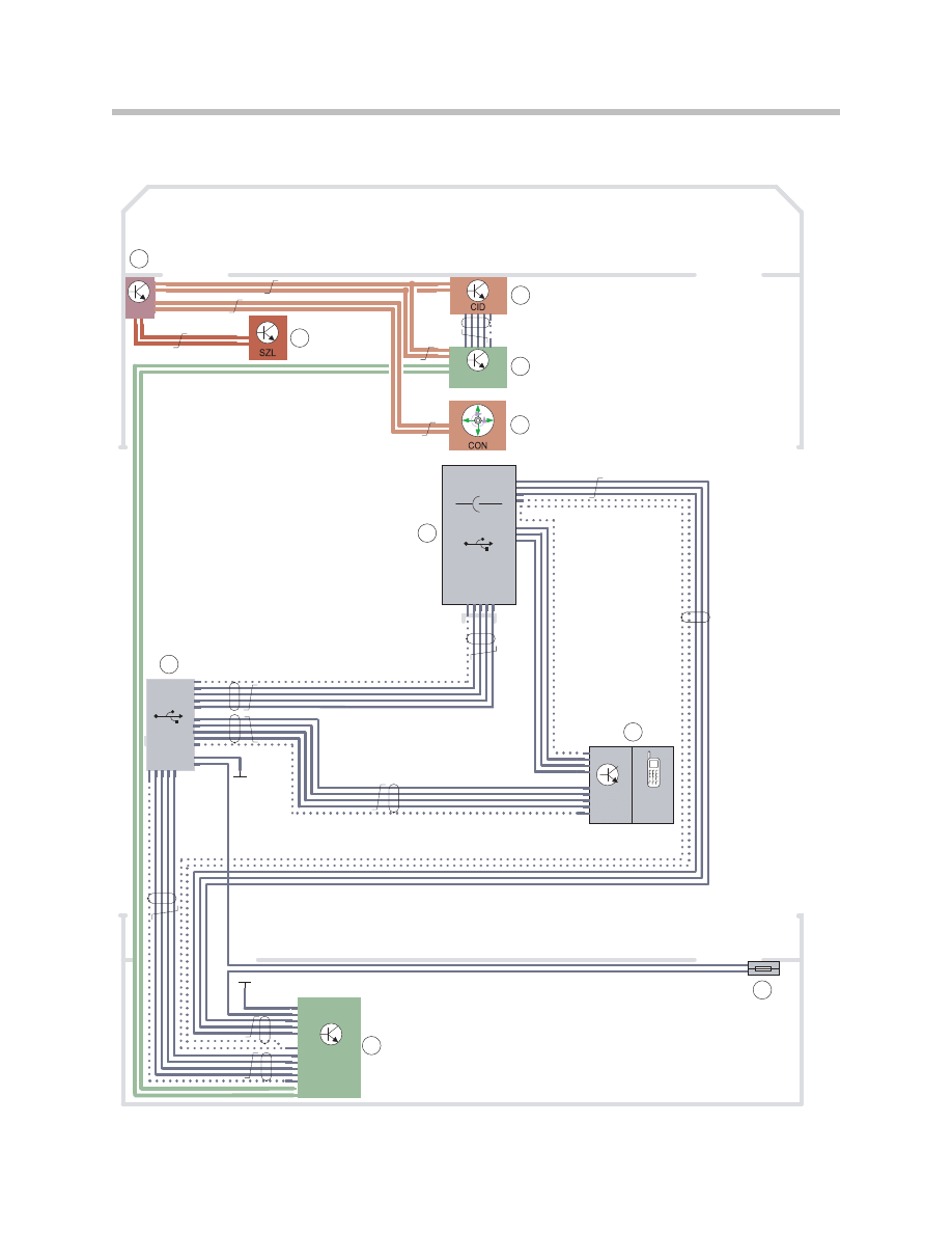
Smartphone Integration Option Circuit Diagram
8
F01 Telephone System
CIC
ZGM
USB Hub
AUX-Buchse
Grund-
platte
Snap-
In
ULF-SBX-H /
TCU
K-CAN
K-CAN
FlexRay
MOST
MOST
USB
USB
1
2
3
4
5
6
10
7
8
9

MOST signals to the ULF-SBX/ULF-SBX-H control units
Note: For detailed information on the Smartphone Integration optional extra
(option 6NF), refer to the F01/F02 Audio systems training material.
9
F01 Telephone System
Index
Explanation
Index
Explanation
1
Central gateway module (ZGM)
6
USB audio interface (AUX)
2
Steering column switch
cluster (SZL)
7
Base plate with snap-in adapter
3
Central Information Display (CID)
8
Fuse in fuse carrier at rear right
4
Car Information Computer (CIC)
9
Interface box (ULF-SBX-H)
5
Controller (CON)
10
USB hub
In/out
Signal
Source/sink
Function
In
Control signals
CIC
Phone book connection set-up,
incoming-call acceptance
In
Control signals
CAS
Terminal control
Out
Control signals
CIC
Audio signals, call recipient,
mobile phone
Input/outputs, Telematics Control Unit
10
F01 Telephone System
TCU
19
1
12
13
18
4
5
7
8
9
6
2
3
15
14
17
20
16
10
11

Voice output by the telephone system is via the vehicle’s front right, front left and center
speakers.
Volume can be adjusted by means of the multifunction steering wheel and the IHKA/
audio control unit.
11
F01 Telephone System
Index
Explanation
Index
Explanation
1
Instrument cluster
11
Car Access System (CAS)
2
Central Information
Display (CID)
12
Roof antennal for TCU and
snap-in cradle adapter and internal
telephone module of the TCU
3
Speaker
13
Snap-in adapter cradle with
mobile phone
4
Roof function module (FZD)
14
Footwell module (FRM) for
remote door unlocking and
remote door locking
5
Microphone (passenger's side)
15
Microphone (driver's side)
6
Wheel speed sensor
16
Telematics Control Unit (TCU)
7
Bluetooth antenna
17
Car Information Computer (CIC)
8
Crash safety module (ACSM)
18
Central gateway module (ZGM)
9
GPS antenna
19
Controller (CON)
10
Emergency-call GSM
antenna (back-up)
20
Multifunction steering
wheel (MFL)
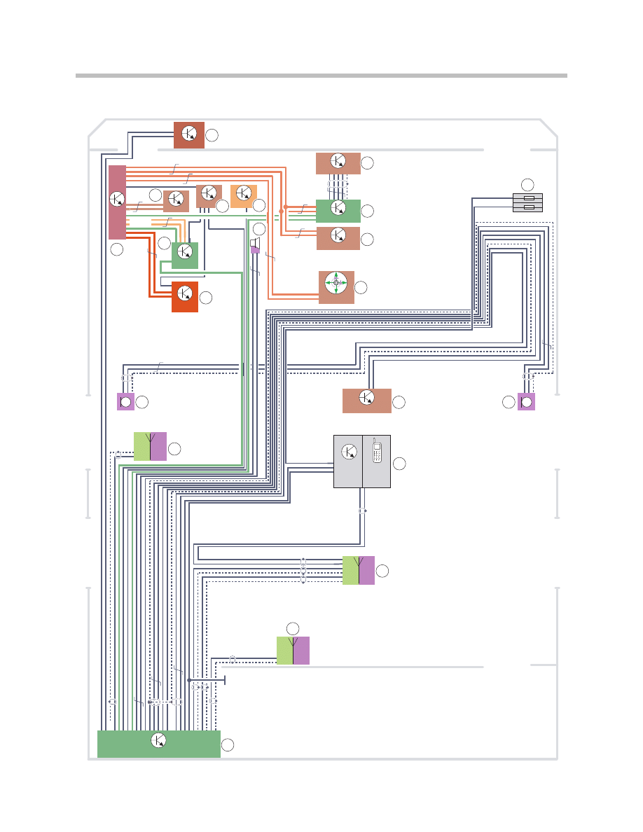
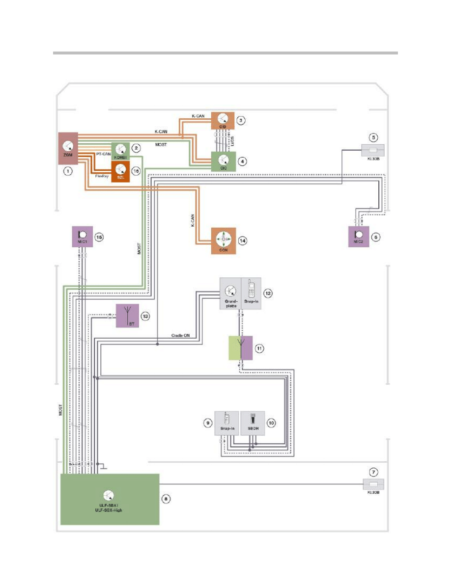
Telematics Control Unit (TCU) Circuit Diagram
12
F01 Telephone System
BT
Grund-
platte
Snap-In
TCU
FZD
CIC
IHKA
CON
B-CAN
K-CAN
K-CAN
MOST
FRM
DSC
KOMBI
SZL
CAS
ACSM
ZGM
LVDS
Fle
xR
ay
MOS
T
PT-CAN
6
1
2
3
4
5
8
9
20
21
15
14
13
10
11
12
16
18
17
19
7

13
F01 Telephone System
Index
Explanation
Index
Explanation
1
Dynamic Stability Control (DSC)
12
Telematics Control Unit (TCU)
2
Central Information Display (CID)
13
Bluetooth antenna
3
Head unit (CIC)
14
Microphone (driver's side)
4
Integrated automatic heater
and A/C control (IHKA)
15
Steering column switch cluster (SZL)
5
Controller (CON)
16
Instrument cluster
6
Fuse in the junction box
17
SOS speaker
7
Microphone (passenger's side)
18
Crash safety module (ACSM)
8
Roof function module (FZD)
19
Car Access System (CAS)
9
Base plate phone snap-in adapter
20
Footwell module (FRM)
10
Roof antenna
21
Central gateway module (ZGM)
11
Emergency-call GSM
antennal (back-up)

MOST signals on the control unit TCU
The TCU receives its power supply via terminal 30F. The power supply via terminal 30F is
necessary for the provision of the BMW ASSIST services, including for example:
• Remote Door Unlock
• Vehicle Finder/Stolen Vehicle Recovery
• Remote Climate Control.
These services are implemented via the MOST bus. The TCU reacts to a call from the
provider, placed at the customer’s request. The TCU sends a signal via the MOST bus to
the Car Access System (CAS). The CAS then wakes up the vehicle.
14
F01 Telephone System
In/out
Signal
Source/sink
Function
In
GPS signals
GPS antenna
to CIC
Position data
In
Control signals
CIC
Phone book, connection set-up,
incoming-call acceptance,
terminal control, etc.
Out
Audio signals
CIC
Audio signals, call recipient BMW ASSIST
Out
Audio signals
CIC
Audio signals, call recipient mobile phone

15
F01 Telephone System
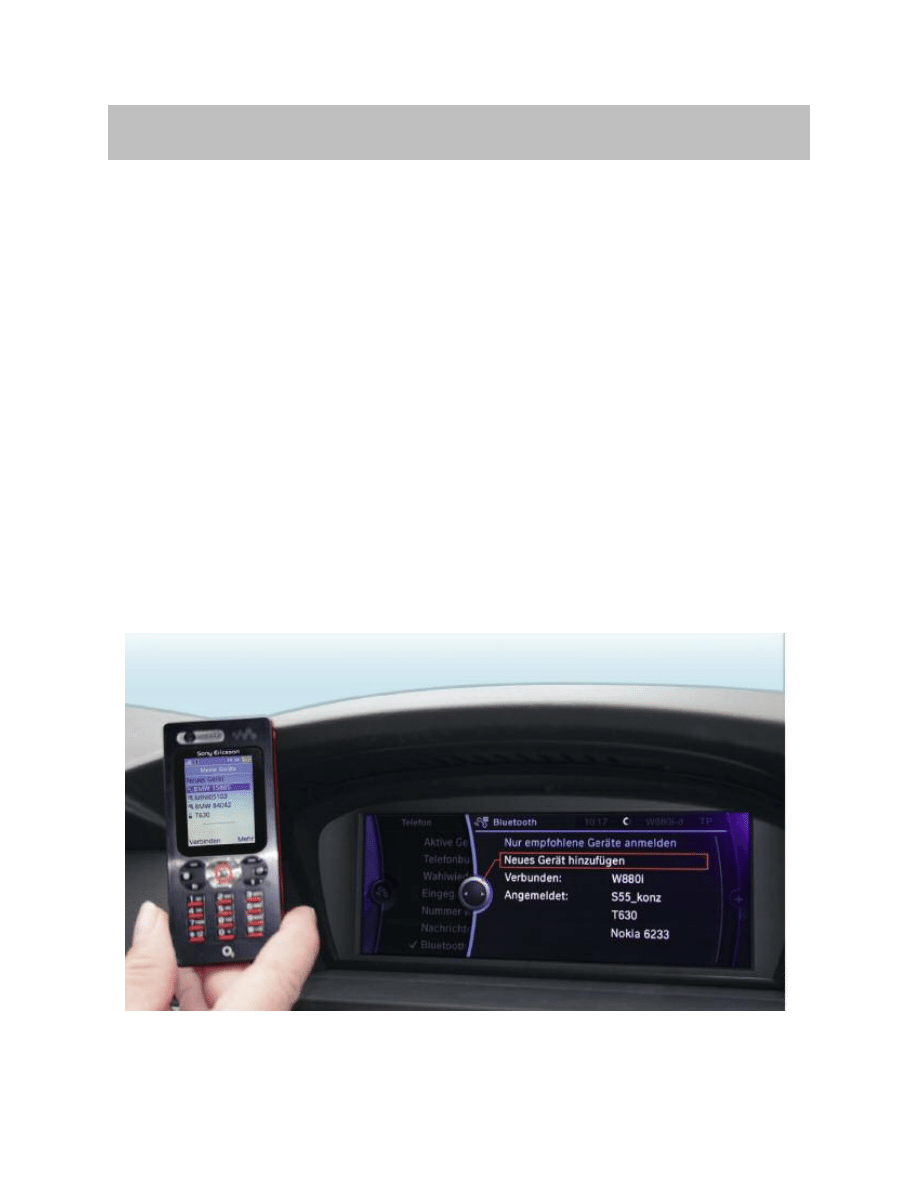
Bluetooth Pairing (pairing wizard)
The pairing wizard presents the step-by-step instructions for the entire pairing process
via the Central Information Display (CID). Detailed help texts and instructions for further
assistance are available in case pairing is not successful.
This pairing wizard for Bluetooth is found by selecting the “Telephone” menu and then
selecting “Bluetooth”.
Pairing process:
• Once “Add new device” has been selected, the in-car display shows the Vehicle
Identification Number (VIN). At the same time, the pairing wizard issues a message
to the effect that from this point on the mobile phone has to be used in the process.
• The mobile phone should now be used to search for new Bluetooth devices.
• If the search is successful, the VIN appears in the display of the mobile phone.
• The next step is to key a freely selectable PIN code into the mobile phone, and then
key the same PIN code into the vehicle.
• If pairing is successful the data of the newly paired mobile wireless device appear in
the vehicle’s phonebook.
• This can take from a few seconds to several minutes to complete, depending on
how many entries there are in the phonebook.
• The telephone entries for the entries from the “Contacts” menu are also shown.
Up to four mobile phones can be paired with the car. Before a fifth mobile phone can be
paired, one of the other four entries must be removed from the list.
Note: Not all system compatible phones are capable of these features.
For more information see a list of compatible phones at
www.wireless4bmw.com
Functions
Calls with Multiple Users
This function can be used to conduct two phone conversations at the same time.
Services such as call waiting, toggle calls and teleconferencing are possible in this way.
Call Waiting
If a second call is incoming while a call is in progress this is indicated by a call waiting
tone and also by an accept/reject prompt in the display. The user can now reject the
second call and continue the active call or accept the second call. In which case the first
caller will hear a call waiting melody and is placed on hold.
Toggle Calls
When calls with multiple users are in progress, one call can be “active” and one “on
hold”.
The “toggle calls” function can be used to toggle these calls between the “active” status
and the “on hold” status.
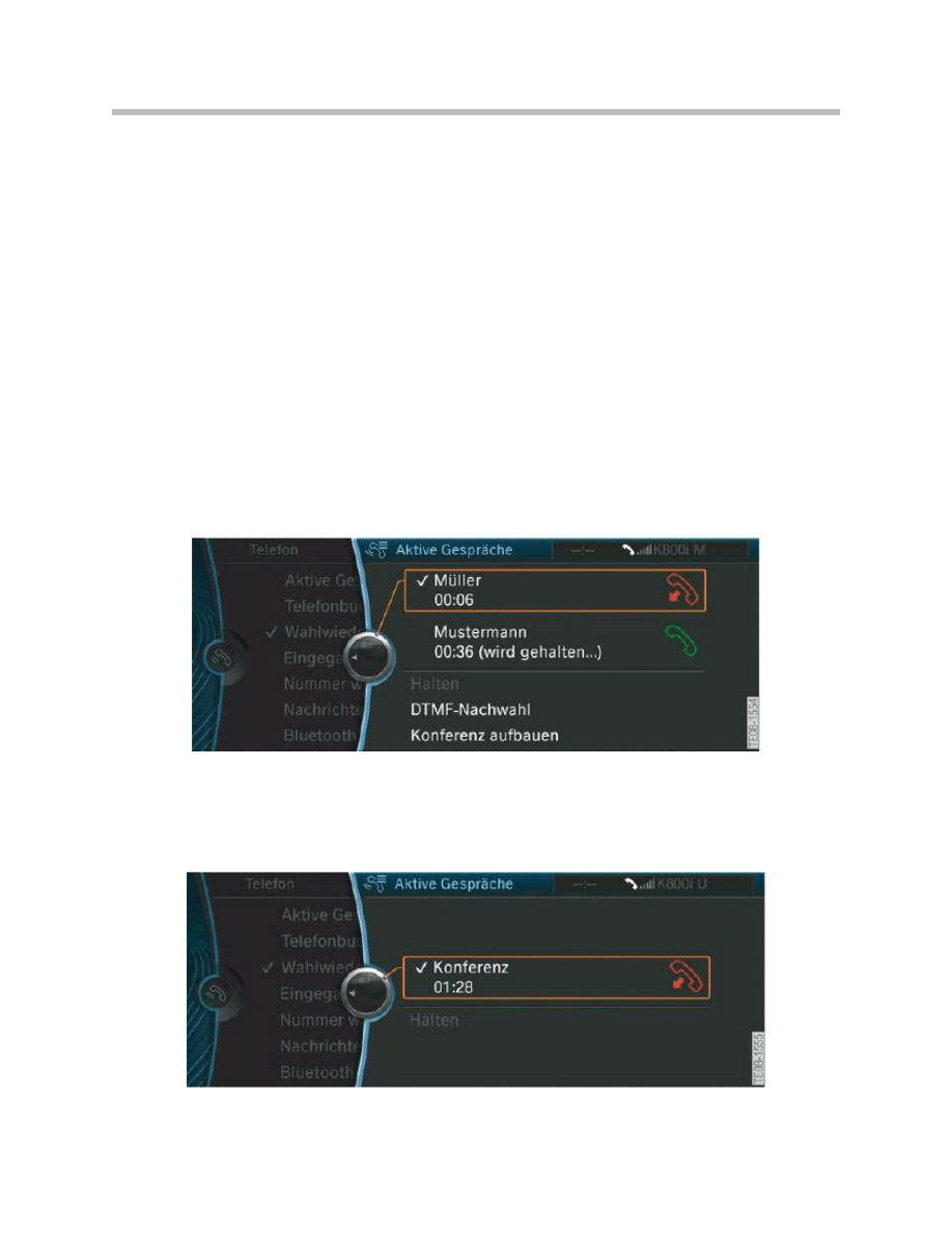
Teleconference
If the user has an active call and a call on hold, the "Conference" menu item can be
selected to place all phone users in a shared conference call.
16
F01 Telephone System
Display showing a teleconference
Display showing active calls
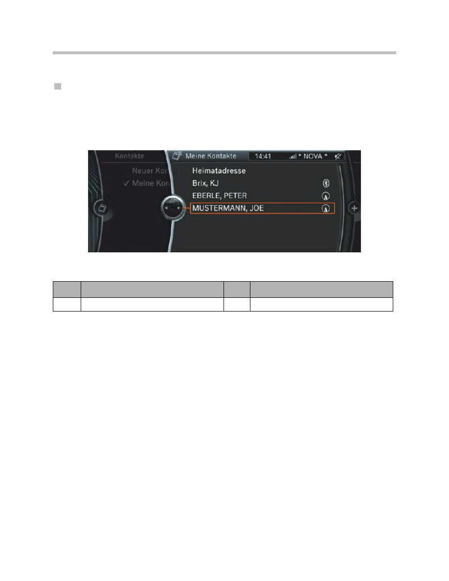
Phonebook Contacts
Contacts
All contact information can be viewed and saved under ‘Contacts’. Contacts transferred
from the user’s mobile phone to the car are also listed here. A symbol after the contact
shows where the information for this contact is saved. When the mobile phone is
removed from the car the contacts from the phone/ Bluetooth pairing can no longer be
selected in the vehicle.
Other information, including e-mail addresses and postal addresses can be saved and
administrated along with the phone numbers on the CIC contacts. This information can
only be transferred from the mobile phone to the car if the former supports the PBAP
(Phone Book Access Profile) function.
Note: Not all system compatible phones are capable of these features.
For more information see a list of compatible phones at
www.wireless4bmw.com.
17
F01 Telephone System
Display showing ‘My contacts’
Index
Explanation
Index
Explanation
1
Contacts from phone/Bluetooth pairing
4
Contact on the hard disc of the CIC
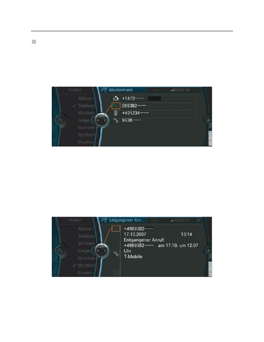
Phonebook
The entries in the phonebook show only contacts for which a phone number has been
saved. These can be either entries from mobile phones or contacts saved in the car. Up
to four telephone numbers can be saved for each contact and the individual numbers
retrieved using the phonebook functionality.
Call Register (Dialled numbers, missed calls)
All dialled numbers and missed calls in the car are listed clearly in the call register under
“Dialled numbers” and “Missed calls”. The entries are sorted by date and time.
The driver uses the controls on the multifunction steering wheel to select from the dialled
numbers list shown in the instrument panel.
18
F01 Telephone System
Display showing the phone numbers for a contact
Displaying showing a missed call
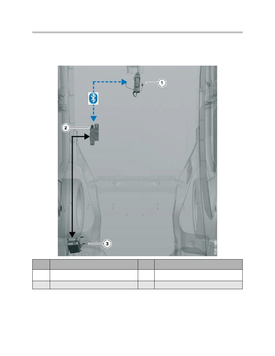
The graphic below shows Bluetooth connections between the Mobile phone in the
center console and TCU are through the Bluetooth antenna.
Note: Although up to four phone may be paired to the vehicle, only one device
can be active at any given time.
19
F01 Telephone System
Index
Explanation
Index
Explanation
1
Front center console with mobile phone
3
Telematics Control Unit (TCU)
2
Bluetooth antenna
Bluetooth connections in the vehicle

BMW Services
These services are offered to customers under the generic term “BMW Assist”.
From the customer’s point of view, “BMW Assist” is a convenient service guaranteeing
more safety, more mobility and comprehensive information.
In an emergency or a breakdown, “BMW Assist” helps save crucial time in might well be
a life-or-death situation, and it also helps the driver in day-to-day situations, such as
searching for a parking space in congested urban areas.
“BMW Assist” is split into two services:
• Safety Plan (Standard)
• Convenience Plan (Optional)
Safety Plan
• Automatic Collision Notification:
Is an emergency calling Service which, in the event of an accident, forwards the rele-
vant GPS data to a rescue-services command post to ensure optimum deployment
of rescue and recovery facilities. If airbags deploy this is fully automatic.
• Emergency Request (SOS):
Pushing the SOS button in an emergency will transmit the vehicle location and infor-
mation. A response specialist will contact the driver to aid in the situation.
• Enhanced Roadside Assistance:
Is used when stranded on the road, to request a tow truck, fuel or a flat tire replace-
ment.
• Stolen Vehicle Recovery:
This service makes it simple to track a stolen vehicle via GPS. The GPS data are for-
warded to the police.
• Remote Door Unlock:
New service enabling the customer to have the doors of the car opened by remote
control in the event of the identification transmitter being locked inside.
• TeleService:
With TeleService the vehicle’s operating status and upcoming service needs are
transmitted to the BMW center automatically or manually with the push of the
“Service Request” menu option in the iDrive display.
20
F01 Telephone System

• Customer Relations:
This service can be used to request day-to-day information about the locality.
Pressing the SOS button or the Customer Relations menu option will contact the
Customer Relations staff.
• My Info:
This enables the customer search Google Maps from a home PC and to send busi-
ness listings, street addresses and phone numbers as well as messages to the vehi-
cle. This information appears on the “My Info” menu and can be exported to the
Navigation system as a new destination.
Convenience Plan (Optional)
• Critical Calling:
This service allows up to four operator assisted calls per year just by pressing the
SOS button. This is useful when the customer is with out a working mobile phone
and need the assistance of a relative or colleague.
• Concierge:
This service accessed through the “Concierge” option in the iDrive. It can be used
to request day-today information about the locality, for example locations of restau-
rants, hotels (including reservation service), addresses, etc.
• Directions:
To receive the shortest route or directions to the nearest gas station, ATM or a point
of interest. Select “Concierge” from the iDrive menu or press the SOS button to
speak to a response specialist
• Traffic Information:
To receive up to date traffic reports along a traveled route, select “Concierge” from
the iDrive menu or press the SOS button to speak to a response specialist.
• Weather Information:
Select “Concierge” from the iDrive menu or press the SOS button to speak to a
response specialist to receive the latest weather forecast, locally or at your destina-
tion.
• BMW Search:
Available only with the Navigation option, BMW Search allows online access to the
Google Maps database from the iDrive. The desired business information (address
and phone number) can then be sent to the navigation system or to the phone
system.
21
F01 Telephone System
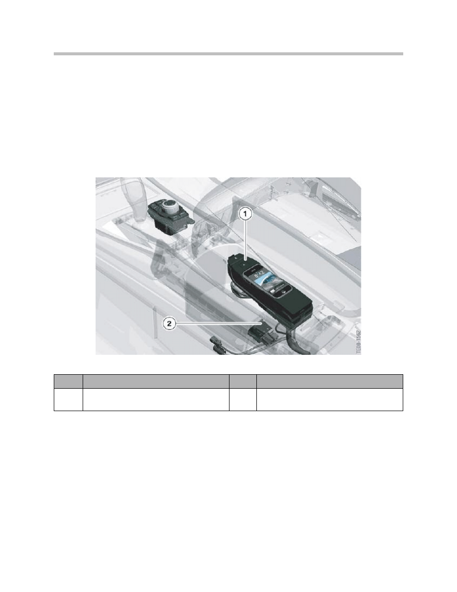
Smartphone Integration
The “Smartphone Integration” optional extra enables the customer to play back audio
files saved on a mobile phone. The option adds a USB port to the telephone base plate
snap in cradle. The mobile phone can be connected to the car with a compatible snap-in
cradle adapter, with all telephone functions remaining fully available.
Simultaneous use of the mobile phone in the snap-in adapter and the USB port in the
center console is possible. However, the audio files on the mobile phone cannot be
accessed while a device is connected to the USB port.
The audio files can be selected in the 'CD/Multimedia' menu, where they are in the
"External devices" submenu.
Smartphone Integration is offered only in combination with "USB audio interface"
option and is currently only available with the iPhone.
Note: For detailed information about these systems, see the F01/F02
“Audio Systems” training material.
22
F01 Telephone System
Smartphone Integrated audio player function
Index
Explanation
Index
Explanation
1
Base plate with snap-in adapter
and mobile phone
2
USB audio interface

Components and Installation Locations
The following control units act as the interface between the mobile phone
and the vehicle:
• ULF-SBX-High Interface box (Only for USB/Audio Interface)
• Telematics Control Unit (TCU)
The preconditions under which TCU or TCU and interface box together
are installed are listed below:
Note: Although both the ULF-SBX-H and the TCU may be fitted in a vehicle at
the same time, the TCU always provides the telephone functions. The
ULF-SBX High is only installed to provide the “USB audio interface”.
23
F01 Telephone System
System Components
Optional extra
Telephone control units installed
Option 639 "BMW Assist"
TCU
Option 639 "BMW Assist" + option 6FL "USB
audio interface"
TCU
ULF-SBX-H
Option 639 "BMW Assist" + option 6NF "Smartphone
Integration"+ option 6FL "USB audio interface"
TCU,
ULF-SBX-H
base plate/cradle adapter
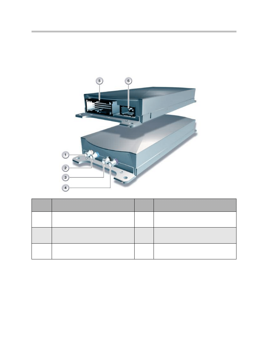
ULF-SBX-H Interface Box
The ULF-SBX High interface box has been used in BMW vehicles since the introduction
of E93.
The (SBX High) interface box is capable of performing the following tasks:
• USB connection for USB/audio interface
• Bluetooth interface with hands-free mode and phone book
• Basic voice input and activation system through the telephone
Interface box and interface box ‘High’ support various techniques for downloading phone
book entries from Bluetooth-enabled mobile phones. One of these techniques is
Phonebook Access Profile (PBAP). The number of compatible mobile phones increases
with the support of several downloading techniques. In addition, it is possible to download
all the phone numbers attached to a name entry.
Although both the ULF-SBX-H and the TCU may be fitted in a vehicle at the same time,
the TCU always provides the telephone functions. In this case the telephone functions
are not available in the ULF-SBX High and the module is only installed to provide the
"USB audio interface" option.
24
F01 Telephone System
Index
Explanation
Index
Explanation
1
Bluetooth connection (Not for US)
3
MOST connection
2
54-pin connector
4
USB connection
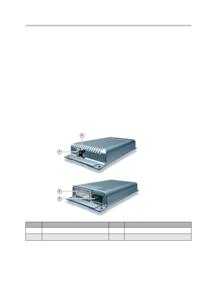
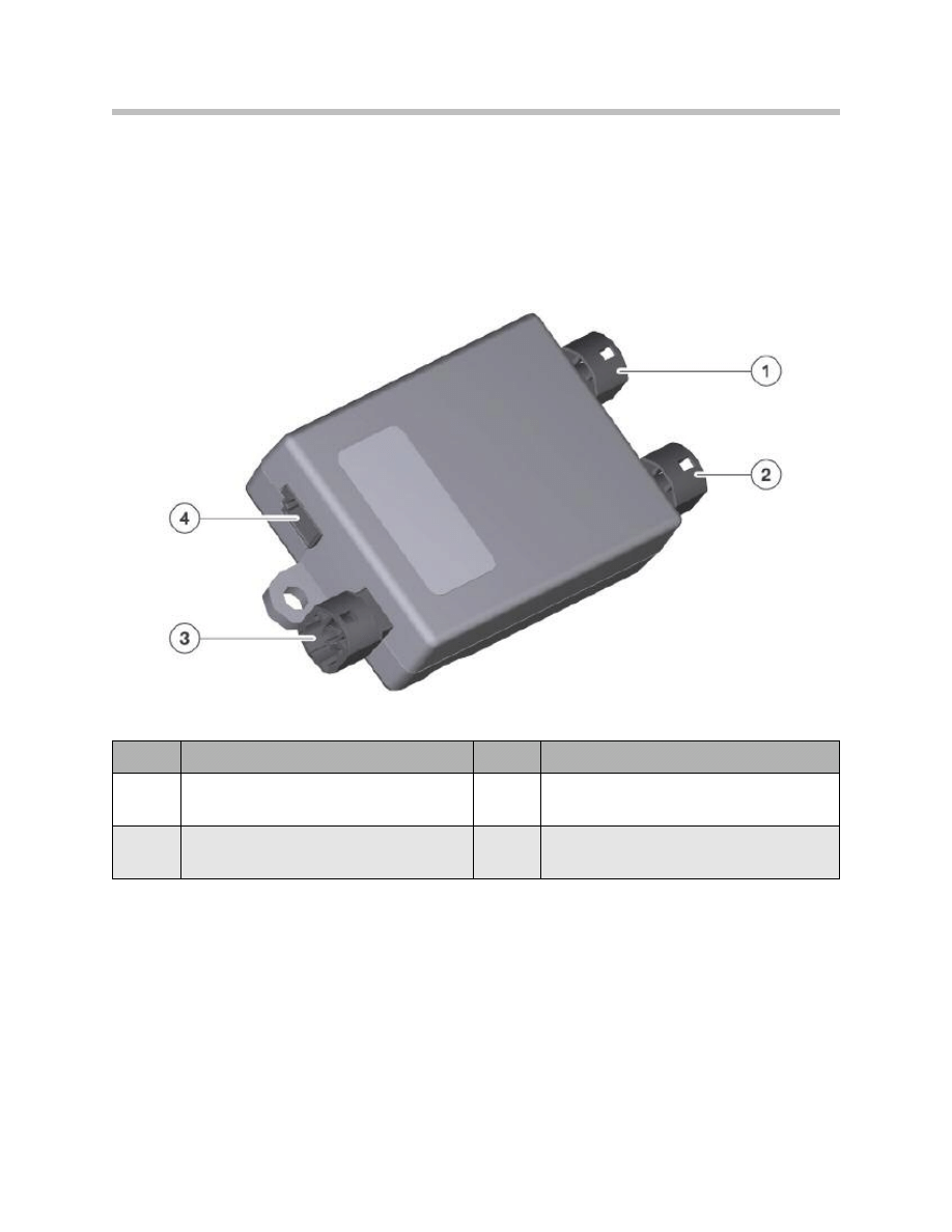
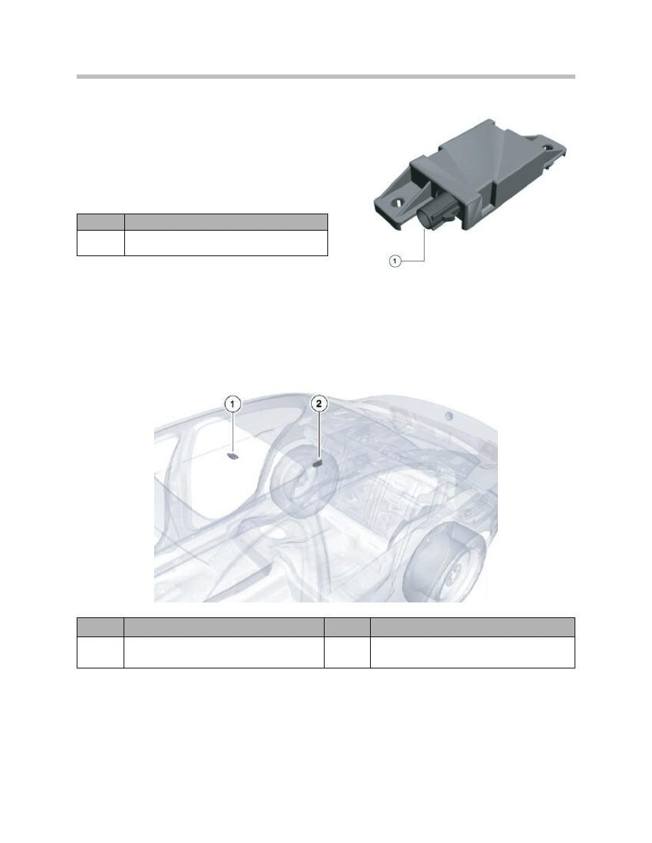
Telematics Control Unit (TCU)
The Telematics Control Unit used on the F01/F02 evolved from the E70 TCU.
The TCU always incorporates a GPS receiver and a GPS connection. In the F01/F02,
however, this connection is not used because the GPS signals are processed by the CIC.
25
F01 Telephone System
Index
Explanation
Index
Explanation
1
Bluetooth antenna connection,
transparent connector
4
Emergency antenna connection
purple connector
2
GPS antenna connection
blue connector
5
54-pin connector
3
Roof antenna connection
black connector
6
MOST connection
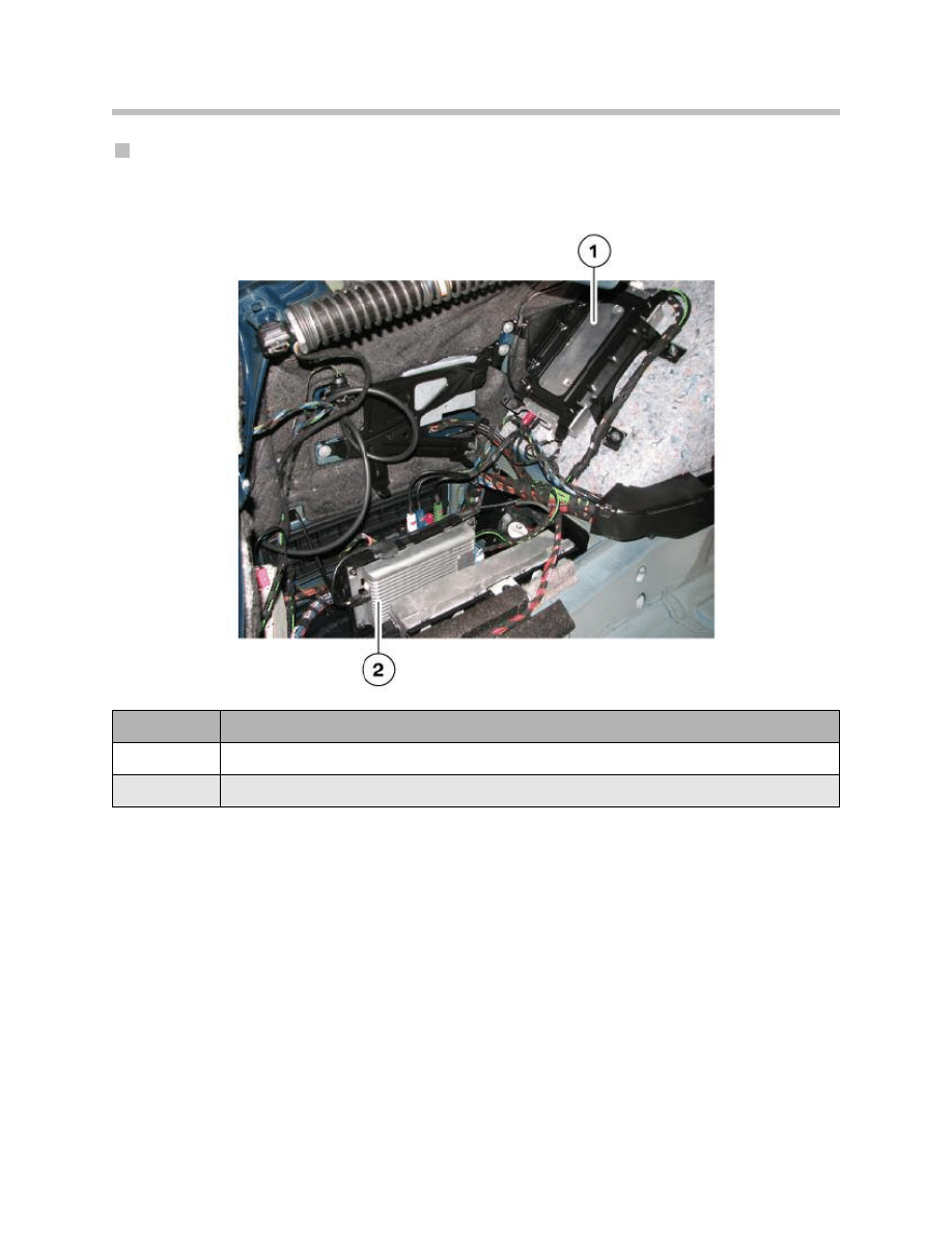
Location of ULF-SBX/ULF-SBX-H and TCU
Interface box or interface box ‘High’ and the TCU are seated in the luggage compartment
on the left.
26
F01 Telephone System
Index
Explanation
1
Telematics control unit (TCU)
2
Interface box (ULF-SBX-High)
USB Hub
The USB hub is for connecting multiple USB interfaces to the interface box 'High'. The
USB hub incorporates an active USB signal amplifier and has two USB inputs and one
USB output.
The USB hub is installed only if the car is ordered with the "Smartphone Integration".
27
F01 Telephone System
Index
Explanation
Index
Explanation
1
USB connection to AUX-in
connection (blue connector)
3
USB connection to
(ULF-SBX-High) interface
box (black connector)
2
USB connection for base plate of the
Smartphone audio link
(neutral color connector)
4
Power supply for the USB hub
(black connector)

Location of USB Hub
The USB hub is installed at the left B pillar. This applies to both RHD and LHD cars.
USB Base Plate/snap-in Adapter
The base plate with snap-in adapter and USB AUX-IN connection are installed in the front
center console, underneath the armrest.
28
F01 Telephone System
Index
Explanation
Index
Explanation
1
Button for removal of the
snap-in adapter
3
Snap-in adapter
2
Button for removal of the
mobile phone
4
USB connection and AUX-IN
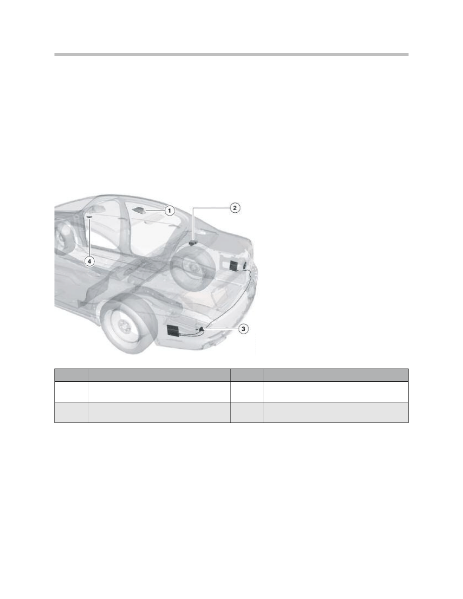
Telephone Antenna System
In order to meet the high quality requirements that apply to the telephone system of the
F01/ F02, several antennas are installed in the vehicle, with the configuration depending
on equipment trim level.
The following antennas are used for this purpose:
• Roof antenna
• Bluetooth antenna
• Emergency-call GSM antenna
Emergency-call GSM antenna
The emergency-call GSM antenna is needed for the ASSIST service so it is installed
in combination with the Telematics Control Unit. “Preparation for mobile phone with
Bluetooth interface”.
29
F01 Telephone System
Index
Explanation
Index
Explanation
1
Roof Antenna
3
Not for US
2
Emergency-call GSM (back-up) antenna
4
Bluetooth antenna
Bluetooth antenna
The Bluetooth antenna is a newly designed
component. It is smaller than the predecessor
model, which means that it can be accommo-
dated in the roof.
There are two different locations for the Bluetooth antenna. The position actually
occupied depends on whether or not the car is fitted with the slide/tilt sunroof option.
30
F01 Telephone System
Index
Explanation
1
Connection to the TCU
Location of the Bluetooth Antenna
Index
Explanation
Index
Explanation
1
Bluetooth antenna without slide/tilt
sunroof (in middle of roof)
2
Bluetooth antenna with slide/tilt
sunroof (on B pillar)

Roof antenna
The roof antenna is in the middle of the roof, toward the trailing edge. Depending on the
equipment installed, the car might have two GSM antennas (roof 1 and roof 2). Both are
inside the housing of the roof antenna.
Overview of the GSM antennas installed and relationship to optional extras:
31
F01 Telephone System
Optional extra
GSM 1
(roof antenna)
GSM 2
(roof antenna)
Emergency-call
GSM antenna
Bumper antenna
BMW Assist
X
X
X
O
Document Outline
- Main Menu
- 01_F01 Introduction
- 02_F01 Powertrain
- 03_F01 Voltage Supply & Bus Systems
- 03.1_F01 Bus Systems
- 03.2_F01 Voltage Supply
- 03.3_F01 Energy Management
- 03.4_F01 Car Access System 4
- 04_F01 Chassis Dynamics
- 04.1_F01 Chassis and Suspension
- 04.2_F01 Dynamic Driving Systems
- 04.3_F01 Longitudinal Dynamics Systems
- 04.4_F01 Lateral Dynamics Systems
- 04.5_F01 Vertical Dynamics Systems
- 04.6_F01 Cruise Control Systems
- 05_F01 General Vehicle Electronics
- 05.1_F01 Comfort Access
- 05.2_F01 Central Locking System
- 05.3_F01 Automatic Soft Close
- 05.4_F01 Power Windows
- 05.5_F01 Sliding Tilting Sunroof
- 05.6_F01 Anti-theft System
- 05.7_F01 Automatic Luggage Compartment Lid
- 05.8_F01 Exterior Lighting
- 05.9_F01 Interior Lighting
- 05.10_F01 Wiper-Washer System
- 05.11_F01 Exterior Rear View Mirrors
- 05.12_F01 Seats
- 05.13_F01 Steering Column Switch Cluster
- 06_F01 Driver Information Systems
- 06.1_F01 Displays Indicators and Controls
- 06.2_F01 Head-up Display
- 06.3_F01 BMW Night Vision 2
- 06.4_F01 Active Blind Spot Detection System
- 06.5_F01 KAFAS
- 06.6_F01 PDC-TRSVC
- 07_F01 Information and Communication Technology
- 07.1_F01 Rear Seat Entertainment Systems
- 07.2_F01 Telephone System
- 07.3_F01 Voice Activation System
- 07.4_F01 Audio Systems
- 08_F01 Climate Control
- 09_F01 Passive Safety Systems
- 10_F01 Service Information
- 10.1_F01 System Functions
- 10.2_ISTA-Programming
Wyszukiwarka
Podobne podstrony:
07 1 F01 Rear Seat Entertainment Systems
07 3 F01 Voice Activation System
07 emission control system
wykład 07 zeszły rok systemy szkolne - Malta, studia, andragogika
PBO G 07 F01 Qualified Suppliers list
HONDA Handsfree Telephone System Operating Instructions
07 Teoria prawa SYSTEM PRAWA
07 Metodyka wdrożenia systemu hurtowni danych
The Telephone System
07 emission control system
07 E70 Audio Systems WB
03 1 F01 Bus Systems
ACURA Handsfree Telephone System Operating Instructions
07.10.12r. - Wykład -Taktyka i
więcej podobnych podstron