
The
Verilog
®
Golden
Reference
Guide
DOULOS

DOULOS
Church Hatch,
22 Market Place,
Ringwood.
Hampshire.
BH24 1AW
England.
Tel (+44) (0)1425 471223
Fax (+44) (0)1425 471573
Email info@doulos.co.uk
URL http://www.doulos.co.uk
© Copyright 1996, Doulos, All Rights Reserved.
No part of this publication may be reproduced, stored in a retrieval
system, or transmitted, in any form or by any means, electronic,
mechanical, photocopying, recording or otherwise, without the
prior written permission of DOULOS. Printed in the United
Kingdom of Great Britain and Northern Ireland.
Version 1.0, August 1996
Verilog-XL
TM
is a trademark and Verilog
®
a registered trademark of
Cadence Design Systems Inc.

The Verilog Golden Reference Guide is a compact quick reference
guide to the Verilog hardware description language, its syntax,
semantics, synthesis and application to hardware design.
The Verilog Golden Reference Guide is not intended as a
replacement for the IEEE Standard Verilog Language Reference
Manual. Unlike that document, the Golden Reference guide does not
offer a complete, formal description of Verilog. Rather, it offers
answers to the questions most often asked during the practical
application of Verilog, in a convenient reference format.
Nor is The Verilog Golden Reference Guide intended to be an
introductory tutorial. Information is presented here in a terse
reference format, not in the progressive and sympathetic manner
necessary to learn a subject as complex as Verilog. However,
acknowledging that those already familiar with computer languages
may wish to use this guide as a Verilog text book, a brief informal
introduction to the subject is given at the start.
The main feature of The Verilog Golden Reference Guide is that it
embodies much practical wisdom gathered over many Verilog
projects. It does not only provide a handy syntax reference; there are
many similar books which perform that task adequately. It also
warns you of the most common language errors, gives clues where
to look when your code will not compile, alerts you to synthesis
issues, and gives advice on improving your coding style.
The Verilog Golden Reference Guide was developed to add value to
the Doulos range of Verilog training courses, and also to complement
HDL PaceMaker, the Verilog Computer Based Training package
from Doulos.
3
Preface

The main body of this guide is divided into three main parts, each of
which is organised alphabetically. Each section is indexed by a key
term which appears prominently at the top of each page. Often you
can find the information you want by flicking through the guide
looking for the appropriate key term. If that fails, there is a full index
at the back.
Most of the information in this guide is organised around the Verilog
syntax headings, but there are additional special sections on Coding
Standards, Design Flow, Errors, Reserved Words and, after the main
alphabetical reference section, Compiler Directives, System Tasks
and Functions and Command Line Options.
If you are new to Verilog, you should start by reading A Brief
Introduction to Verilog, which follows overleaf.
The Index
Bold index entries have corresponding pages in the main body of the
guide. The remaining index entries are followed by a list of
appropriate page references in the alphabetical reference sections,
given in order of importance.
Key To Notation Used To Define Verilog Syntax
The syntax definitions are written to look like examples wherever
possible, but it has been necessary to introduce some extra notation.
In brief, square brackets [] enclose optional items, three dots ... means
repetition, and curly brackets {} enclose comments. ItalicNames
represent parts of the syntax defined elsewhere. A full description of
the notation follows:
Curly brackets {} enclose comments that are not part of the Verilog
syntax being defined, but give you further information about the
syntax definition. Bold curly brackets {} are part of the Verilog syntax
(concatenation operator).
Syntax enclosed in square brackets [] is optional. Bold square
brackets [] are part of the Verilog syntax (vector range, bit and part
select, memory element).
...
means zero or more repetitions of the preceding item or line, or
means a list, as follows:
Item ... means zero or more repetitions of the Item.
, ...
means repeat in a comma separated list (e.g. A, B, C).
4
Using This Guide

There must be at least one item in the list. There is no , at the end of
the list.
Words in lower-case letters are reserved words, built into the Verilog
language (e.g. module)
Capitalised Words (not in italics) are Verilog identifiers, i.e. user
defined names that are not reserved identifiers (e.g. InstanceName).
Italic Words are syntactic categories, i.e. the name of a syntax
definition given in full elsewhere. A syntactic category can be either
defined on the same page, defined on a separate page, or one of the
special categories defined below.
Italics = indicates a syntactic category which is defined and used on
the same page.
Special syntactic categories:
MinTypMaxExpression is defined with Expression.
UnsignedNumber is defined with Number.
SomethingExpression = Expression, where the Something gives
information about the meaning of the expression (e.g.
ConstantExpression, ConstantMinTypMaxExpression).
5

The following paragraphs give a brief technical introduction to
Verilog suitable for the reader with no prior knowledge of the
language.
Background
The Verilog Hardware Description Language (HDL) is a language for
describing the behaviour and structure of electronic circuits, and is
an IEEE standard (IEEE Std. 1364-1995).
Verilog is used to simulate the functionality of digital electronic
circuits at levels of abstraction ranging from stochastic and pure
behaviour down to gate and switch level, and is also used to
synthesize (i.e. automatically generate) gate level descriptions from
more abstract (Register Transfer Level) descriptions. Verilog is
commonly used to support the high level design (or language based
design) process, in which an electronic design is verified by means of
thorough simulation at a high level of abstraction before proceeding
to detailed design using automatic synthesis tools. Verilog is also
widely used for gate level verification of ICs, including simulation,
fault simulation and timing verification.
The Verilog HDL was originally developed together with the
Verilog-XL simulator by Gateway Design Automation, and
introduced in 1984. In 1989 Cadence Design Systems acquired
Gateway, and with it the rights to the Verilog language and the
Verilog-XL simulator. In 1990 Cadence placed the Verilog language
(but not Verilog-XL) into the public domain. A non profit making
organisation, Open Verilog International (OVI) was formed with the
task of taking the language through the IEEE standardization
procedure, and Verilog became an IEEE standard in 1995. OVI will
continue to maintain and develop the language.
The Language
In this section as in the rest of the guide, words given in Capitalised
Italics are technical terms whose definitions may be found in the
main body of this guide.
An hierarchical portion of a hardware design is described in Verilog
by a Module. The Module defines both the interface to the block of
hardware (i.e. the inputs and outputs) and its internal structure or
behaviour.
A number of primitives, or Gates, are built into the Verilog language.
They represent basic logic gates (e.g. and, or). In addition User
Defined Primitives (UDPs) may be defined.
6
A Brief Introduction To Verilog

The structure of an electronic circuit is described by making Instances
of Modules and Primitives (UDPs and Gates) within a higher level
Module, and connecting the Instances together using Nets. A Net
represents an electrical connection, a wire or a bus. A list of Port
connections is used to connect Nets to the Ports of a Module or
Primitive Instance, where a Port represents a pin. Registers (see below)
may also be connected to the input Ports (only) of an Instance.
Nets (and Registers) have values formed from the logic values 0, 1, X
(unknown or uninitialised) and Z (high impedance or floating). In
addition to logic values, Nets also have a Strength value. Strengths are
used extensively in switch level models, and to resolve situations
where a net has more than one driver.
The behaviour of an electronic circuit is described using Initial and
Always constructs and Continuous Assignments. Along with UDPs and
Gates these represent the leaves in the hierarchy tree of the design.
Each Initial, Always, Continuous Assignment, UDP and Gate Instance
executes concurrently with respect to all others, but the Statements
inside an Initial or Always are in many ways similar to the statements
in a software programming language. They are executed at times
dictated by Timing Controls, such as delays, and (simulation) event
controls. Statements execute in sequence in a Begin-End block, or in
parallel in a Fork-Join block. A Continuous Assignment modifies the
values of Nets. An Initial or Always modifies the values of Registers.
An Initial or Always can be decomposed into named Tasks and
Functions, which can be given arguments. There are also a number of
built in System Tasks and Functions. The Programming Language
Interface (PLI) is an integral part of the Verilog language, and
provides a means of calling functions written in C in the same way as
System Tasks and Functions.
Compilation
Verilog source code is usually typed into one or more text files on a
computer. Those text files are then submitted to a Verilog compiler
or interpreter which builds the data files necessary for simulation or
synthesis. Sometimes simulation immediately follows compilation
with no intermediate data files being created.
7

Module Structure
module M (P1, P2, P3, P4);
input P1, P2;
output [7:0] P3;
inout P4;
reg [7:0] R1, M1[1:1024];
wire W1, W2, W3, W4;
parameter C1 = "This is a string";
initial
begin : BlockName
//
Statements
end
always
begin
//
Statements
end
//
Continuous assignments...
assign W1 = Expression;
wire (Strong1, Weak0) [3:0] #(2,3) W2 = Expression;
//
Module instances...
COMP U1 (W3, W4);
COMP U2 (.P1(W3), .P2(W4));
task T1;
input A1;
inout A2;
output A3;
begin
//
Statements
end
endtask
function [7:0] F1;
input A1;
begin
//
Statements
F1 = Expression;
end
endfunction
endmodule
8
Syntax Summary

Statements
#delay
wait (Expression)
@(A or B or C)
@(posedge Clk)
Reg = Expression;
Reg <= Expression;
VectorReg[Bit] = Expression;
VectorReg[MSB:LSB] = Expression;
Memory[Address] = Expression;
assign Reg = Expression
deassign Reg;
TaskEnable(...);
disable TaskOrBlock;
-> EventName;
if (Condition)
...
else if (Condition)
...
else
...
case (Selection)
Choice1 :
...
Choice2, Choice3 :
...
default :
...
endcase
for (I=0; I<MAX; I=I+1)
...
repeat (8)
...
while (Condition)
...
forever
...
This quick reference syntax summary does not follow the notational conventions
used in the rest of the Guide.
9

10

The
Verilog
Golden
Reference
Guide
Alphabetical Reference Section
11

Contains one or more statements (procedural assignments, task enables, if,
case and loop statements), which are executed repeatedly throughout a
simulation run, as directed by their timing controls.
Syntax
always
Statement
Where
module-<HERE>-endmodule
Rules
Only registers (reg, integer, real, time, realtime) may be assigned in an
always.
Every always starts executing at the start of simulation, and continues
executing throughout simulation; when the last statement in the always is
reached, execution continues from the top of the always.
Gotchas!
An always containing more than one statement must enclose the statements
in a begin-end or fork-join block.
An always with no timing controls will loop forever.
Synthesis
always is one of the most useful Verilog statements for synthesis, yet an
always is often unsynthesizable. For best results, code should be restricted
to one of the following templates:
always @(Inputs)
//
All the inputs
begin
...
//
Combinational logic
end
always @(Inputs)
//
All the inputs
if (Enable)
begin
...
//
Latched actions
end
12
Always

always @(posedge Clock) //
Clock only
begin
...
//
Synchronous actions
end
always @(posedge Clock or negedge Reset)
//
Clock and Reset only
begin
if (!Reset)
//
Test active level of asynchronous reset
...
//
Asynchronous actions
else
...
//
Synchronous actions
end
//
Gives flipflops + logic
Example
The following example shows a Register Transfer Level always:
always @(posedge Clock or negedge Reset)
begin
if (!Reset)
//
Asynchronous reset
Count <= 0;
else
if (!Load)
//
Synchronous load
Count <= Data;
else
Count <= Count + 1;
end
The following example shows an always which describes combinational logic:
always @(A or B or C or D)
begin
R = {A, B, C, D}
F = 0;
begin : Loop
integer I;
for (I = 0; I < 4; I = I + 1)
if (R[I])
begin
F = I;
disable Loop;
end
end //
Loop
end
See Also
Begin, Fork, Initial, Statement, Timing Control
13

Used to group statements, so that they execute in sequence. The Verilog
syntax often requires exactly one statement, for example in an always. If
more than one statement is needed, the statements may be included in a
begin-end block.
Syntax
begin [:
Label
[
Declarations...
]]
Statements...
end
Declaration =
{either}
Register Parameter Event
Where
See Statement.
Rules
A begin-end block must contain at least one statement.
Statements in a begin-end block are executed in sequence. Timing controls
are relative to the previous statement. The begin-end block completes when
the bottom-most statement has completed.
Begin-end and fork-join blocks may be nested within themselves and each
other.
If a begin-end block is to contain local declarations, it must be named (i.e. it
must have a label).
If a begin-end block is to be disabled, it must be named.
Gotchas!
The Verilog LRM allows begin-end blocks to be interleaved during simulation.
This means that even where a begin-end block contains two adjacent
statements with no timing control between them, a simulator may choose to
execute part of another process (E.g. statements in another always) between
the two statements. This is a source of non-determinism in the language.
Tips
Begin-end blocks can be labelled to improve readability, even if there are no
local declarations, and the block is not to be disabled.
Use local declarations for registers that will not be used elsewhere. This
makes the intent of the declaration explicit.
14
Begin

Example
initial
begin : GenerateInputs
integer I;
for (I = 0; I < 8; I = I + 1)
#Period {A, B, C} = I;
end
initial
begin
Load = 0;
//
Time 0
Enable = 0;
Reset = 0;
#10 Reset = 1;
//
Time 10
#25 Enable = 1;
//
Time 35
#100 Load = 1;
//
Time 135
end
See Also
Fork, Disable, Statement.
15

A statement which conditionally executes at most one branch, depending on
the value of the case expression.
Syntax
CaseKeyword
(
Expression
)
Expression,...
:
Statement
{Expression may be variable}
Expression,...
:
Statement
...
{Any number of cases}
[default [:]
Statement
]
{Need not be at the end}
endcase
CaseKeyword =
{either}
case casex casez
Where
See Statement.
Rules
Xs and Zs in a casex statement, and Zs in a casez statement mean “don’t
care”.
One default statement at most may be included. It is executed if no label
expressions match the case expression. (A ‘label’ is an expression or a
comma-separated list of expressions on the left of a colon, or the reserved
word default, which may or may not be followed by a colon.)
Where a label is a comma-separated list of two or more expressions, the label
is matched if the case expression matches any one of the label expressions.
If no label expressions match the case expression and there is no default
statement, the case statement has no effect.
Gotchas!
If more than one statement is to be executed for a particular label, the
statements must be enclosed in a begin-end or fork-join block.
A branch is only executed if the corresponding label is the first one to match
the case expression. Case labels need not be mutually exclusive, so a
Verilog compiler will not report an error where the same label has erroneously
been repeated.
The syntax of a casex or casez statement ends with the reserved word
endcase, not endcasex or endcasez.
An X or Z in the casex expression or a Z in a casez expression is matched
with any value in a case label. This may give confusing simulation results.
Synthesis
Assignments within case statements generally synthesize to multiplexers. If
variables (i.e. registers or nets) are used for case labels, priority encoders
may be synthesized.
16
Case

Incomplete assignments (i.e. where outputs remain unassigned for certain
input conditions) in an unclocked always synthesize to transparent latches.
Incomplete assignments in a clocked always synthesize to recirculation
around registers.
Tips
For simulation, always use default as the last case statement, to trap illegal
conditions.
casez is usually preferable to casex, because the presence of Xs in
simulation may give misleading or confusing results.
Use the alternative character ? for Z in casex and casez labels. This makes it
clear that a “don’t care” value and not a high impedance value is intended.
Example
case (Address)
0 : A <= 1;
//
Select a single Address value
1 : begin
//
Execute more than one statement
A <= 1;
B <= 1;
end
2, 3, 4 : C <= 1;
//
Pick out several Address values
default :
//
Mop up the rest
$display("Illegal Address value %h in %m at %t",
Address, $realtime);
endcase
casex (Instruction)
8'b000xxxxx : Valid <= 1;
8'b1xxxxxxx : Neg <= 1;
default
begin
Valid <= 0;
Neg <= 0;
end
endcase
casez ({A, B, C, D, E[3:0]})
8'b1??????? : Op <= 2'b00;
8'b010????? : Op <= 2'b01;
8'b001???00 : Op <= 2'b10;
default : Op <= 2'bxx;
endcase
See Also
If
17

Coding standards are divided into two categories. Lexical coding standards,
which control text layout, naming conventions and commenting, are intended
to improve readability and ease of maintenance. Synthesis coding standards,
which control Verilog style, are intended to avoid common synthesis pitfalls
and find synthesis errors early in the design flow.
The following lists of coding standards will need to be modified according to
the choice of tools and personal preferences.
Lexical Coding Standards
Limit the contents of each Verilog source file to one module, and do not split
modules across files.
Source file names should relate to the file contents (e.g. ModuleName.v).
Write only one declaration or statement per line.
Use indentation as shown in the examples.
Be consistent about the case of user defined names (e.g. first letter a capital).
User defined names should be meaningful and informative, although local
names (e.g. loop variables) may be terse.
Write comments to explain (not duplicate) the Verilog code. It is particularly
important to comment interfaces (e.g. module parameters, ports, task and
function arguments).
Use parameters or `define macros wherever possible, instead of directly
embedding literal numbers and strings in declarations and statements.
Synthesis Coding Standards
Partition the design into small functional blocks, and use a behavioural style
for each block. Avoid gate level descriptions except for critical parts of the
design.
Have a well defined clocking strategy, and implement that strategy explicitly in
Verilog (e.g. single clock, multi-phase clocks, gated clocks, multiple clock
domains). Ensure that clock and reset signals in Verilog are clean (i.e. not
generated from combinational logic or unintentionally gated).
Have a well defined (manufacturing) testing strategy, and code up the Verilog
appropriately (e.g. all flipflops resettable, test access from external pins, no
functional redundancy).
Every Verilog always should conform to one of the standard synthesizable
process templates (see
Always
).
An always describing combinational and latched logic must have all of the
inputs in the event control list at the top of the always.
A combinational always must not contain incomplete assignments, i.e. all
outputs must be assigned for all combinations of input values.
An always describing combinational and latched logic must not contain
feedback, i.e. registers assigned as outputs from the always must not be
read as inputs to the always.
18
Coding Standards

A clocked always must have only the clock and any asynchronous control
inputs (usually reset or set) in the event control list.
Avoid unwanted latches. Unwanted latches are caused by incomplete
assignments in an unclocked always.
Avoid unwanted flipflops. Flipflops are synthesized when registers are
assigned in a clocked always using a non-blocking assignment, or when
registers retain their value between successive iterations of a clocked always
and thus between clock cycles).
All internal state registers must be resettable, in order that the Register
Transfer Level and gate level descriptions can be reset into the same known
state for verification. (This does not apply to pipeline or synchronization
registers.)
For finite state machines and other sequential circuits with unreachable states
(e.g. a 4 bit decade counter has 6 unreachable states), if the behaviour of the
hardware in such states is to be controlled, then the behaviour in all 2
N
possible states must be described explicitly in Verilog, including the behaviour
in unreachable states. This allows safe state machines to be synthesized.
Avoid delays in assignments, except where necessary to solve the problem of
zero delay clock skew at Register Transfer Level.
Do not use registers of type integer or time, otherwise they will synthesize to
32 bit busses and 64 bit busses respectively.
Check carefully any Verilog code which uses dynamic indexing (i.e. a bit
select or memory element using a variable index or address), loop
statements, or arithmetic operators, because such code can synthesize to
large numbers of gates which can be hard to optimize.
19

Comments may be (should be!) included to document the Verilog source
code.
Syntax
{single line comment}
//
{multi-line comment}
/* ... */
Where
Nearly anywhere, but not so as to split operators, numbers, strings, names
and keywords.
Rules
A single line comment starts with the two slash characters and ends at the
end of the line.
A multi-line comment starts with /* and continues, possibly across multiple
lines, until the next */
Multi-line comments may not be nested. However, there may be single line
comments inside a multi-line comment, where they have no special meaning.
Gotchas!
/* ... /* ... */ ... */ - the comment ends at the first */, and the second /* is
ignored. This would almost certainly give syntax errors.
Tips
Use single line comments throughout. Only use multi-line comments where it
is necessary to comment out a large section of code, for example during
development and debugging of the code.
Example
// This is a comment
/*
So is this - across three lines
*/
module ALU /* 8-bit ALU */ (A, B, Opcode, F);
See Also
Coding Standards
20
Comment

A continuous assignment creates events on one or more nets whenever a net
or register in an expression changes value.
Syntax
{either}
assign [
Strength
] [
Delay
]
NetLValue = Expression,
NetLValue = Expression,
...
;
NetType
[
Expansion
]
[
Strength
]
[
Range
] [
Delay
]
NetName =
Expression,
NetName =
Expression,
...
;
{See Net}
NetLValue
=
{either}
NetName
NetName[
ConstantExpression
]
NetName[
ConstantExpression
:
ConstantExpression
]
{
NetLValue
,...}
Where
module-<HERE>-endmodule
Rules
The two forms of continuous assignment have the same effect.
The nets on the left hand side of an assign must have been declared
explicitly in the source code before the continuous assignment statement.
Gotchas!
Continuous assignments are not the same as procedural continuous
assignments, although they are similar. Make sure that you place assign in
the correct place. A continuous assignment goes outside any initial or
always. A procedural continuous assignment goes where statements are
allowed (inside initial, always, task, function etc.).
Synthesis
Delays and strengths are ignored by synthesis tools; use tool specific timing
constraints instead.
Continuous assignments are synthesized as combinational logic.
Tips
Use continuous assignments to describe combinational logic that can easily
be described using a straightforward expression. Functions can be used to
structure expressions. An always is usually better for describing more
complex combinational logic, and may simulate more quickly than a number
of separate continuous assignment statements.
21
Continuous Assignment

Continuous assignments are useful for transferring register values to nets,
when Verilog requires nets to be used. For example, to apply test stimulus
described in an initial to an inout port of a module instance.
Example
wire cout, cin;
wire [31:0] sum, a, b;
assign {cout, sum} = a + b + cin;
wire enable;
reg [7:0] data;
wire [7:0] #(3,4) f = enable ? data : 8'bz;
See Also
Net, Force, Procedural Continuous Assignment
22

Overrides parameter values at compile time. Using hierarchical names,
parameter values can be overridden from anywhere inside or outside a
design’s hierarchy.
Syntax
defparam ParameterName =
ConstantExpression,
ParameterName =
ConstantExpression,
...
;
Where
module-<HERE>-endmodule
Synthesis
Not generally synthesizable.
Tips
Do not use defparam! It used to provide a useful way of back-annotating
layout delays, but this is now normally done using specify blocks and the
Programming Language Interface. To override the values of parameters, use
the # syntax in a module instantiation.
Example
`timescale 1ns / 1ps
module LayoutDelays;
defparam Design.U1.T_f = 2.7;
defparam Design.U2.T_f = 3.1;
...
endmodule
module Design (...);
...
and_gate U1 (f, a, b);
and_gate U2 (f, a, b);
...
endmodule
module and_gate (f, a, b);
output f;
input a, b;
parameter T_f = 2;
and #(T_f) (f,a,b);
endmodule
See Also
Name, Instantiation, Parameter
23
Defparam

Delays may be specified for instances of UDPs and gates, for continuous
assignments, and for nets. These delays model the propagation delay of
components and connections in a netlist.
Syntax
{either}
#
DelayValue
#(
DelayValue
[,
DelayValue
[,
DelayValue
]])
{Rise,Fall,Turn-Off}
DelayValue
=
{either}
UnsignedNumber
ParameterName
ConstantMinTypMaxExpression
Where
See Continuous Assignment, Instantiation, Net.
Rules
Where only one delay value is given, it represents both the rising and falling
propagation delays (i.e. transition to 1 or 0 respectively), and the turn off delay
(if applicable).
Where two delay values are given, the first is the rise delay and the second is
the fall delay, except for tranif0, tranif1, rtranif0 and rtranif1, where the first
value is the turn on delay, and the second is the turn off delay.
Where three delay values are given, the third delay is the turn off delay
(transition to Z), except for trireg nets, where the third delay is the charge
decay time.
Delay to X is the smallest of the specified delays.
For vectors, a transition from non-zero to zero is considered to be a ‘fall’, a
transition to Z is considered to be a ‘turn-off’, and any other transitions are
considered to be a ‘rise’.
Gotchas
Many tools insist that MinTypMax expressions in delays must always be
bracketed. For example #(1:2:3) is allowed, but #1:2:3 is not.
Synthesis
Delays are ignored by synthesis tools. Delays in synthesized netlists are
constrained by synthesis tool commands, such as setting the maximum clock
period.
Tips
Specify block delays (path delays) are usually a more accurate way of
modelling delays, and provide a mechanism for delay calculation and
backannotation of layout information.
24
Delay

See Also
Net, Instantiation, Continuous Assignment, Specify, Timing Control
25

The basic flow for using Verilog and synthesis to design an ASIC or complex
FPGA is shown below. Iteration around the design flow is necessary, but is
not shown here. Also, the design flow must be modified according to the kind
of device being designed and the specific application.
1
System analysis and specification
2
System partitioning
2.1
Top level block capture
2.2
Block size estimation
2.3
Initial floorplanning
3
Block level design. For each block:
3.1
Write Register Transfer Level Verilog
3.2
Synthesis coding checks
3.3
Write Verilog test fixture
3.4
Verilog simulation
3.5
Write synthesis scripts - constraints, boundary conditions, hierarchy
3.6
Initial synthesis - analysis of gate count and timing
4
Chip integration. For complete chip:
4.1
Write Verilog test fixture
4.2
Verilog simulation
4.3
Synthesis
4.4
Gate level simulation
5
Test generation
5.1
Modify gate level netlist for test
5.2
Generate test vectors
5.3
Simulate testable netlist
6
Place and route (or fit) chip
7
Post layout simulation, fault simulation and timing analysis
26
Design Flow

Causes the execution of an active task or named block to terminate before all
its statements have been executed.
Syntax
disable BlockOrTaskName;
Where
See Statement.
Rules
Disabling a named block (begin-end or fork-join) or a task disables all tasks
enabled from that block or task, and downwards through the hierarchy of
enabled tasks. Execution continues with the statement following the disabled
task enable statement or named block.
A named block or task may be self-disabled by a disable statement inside
that named block or task.
The following are not specified when a task is disabled: the values of any
outputs or inouts; events scheduled by non-blocking assignments that have
not yet taken effect; assign and force statements.
Functions cannot be disabled.
Gotchas!
If a task disables itself, this is not the same as returning from the task, as the
outputs will not be defined.
Synthesis
disable is only synthesizable when a named block or task disables itself.
Tips
Use disable as a means of exiting early from tasks, and for exiting loops or
continuing with the next iteration of a loop.
Example
begin : Break
forever
begin : Continue
...
disable Continue;
//
Continue with next iteration
...
disable Break;
//
Exit the forever loop
...
end //
Continue
end //
Break
27
Disable

This is a list of the most common Verilog errors. The top five account for
about 50% of all errors.
The Top 5 Verilog Errors
The left hand side of a procedural assignment not declared as a register.
Missing or mismatched begin-end statements.
Missing base ('b) for binary numbers (this means the compiler considers them
to be decimal numbers).
Using the wrong apostrophe in compiler directives (should be the backwards
apostrophe, or grave accent, `) and number bases (should be the normal
apostrophe, or inverted comma, ').
Missing semicolon at the end of a statement.
Other Common Errors
Trying to define task and function arguments in brackets after the name of the
task or function.
Forgetting to instance the module under test in a test fixture.
Using a procedural continuous assignment instead of a continuous
assignment (i.e. ‘assign’ in the wrong place).
Trying to use reserved words as identifiers (e.g. xor).
No timing controls in an always (causes it to loop indefinitely).
Using a logical or operator ( || ) instead of the reserved word or in an event
control (E.g. @(a or b) ).
Using implicit wires for connections to vector ports.
Connecting ports in the wrong order in a module instance.
Incorrect bracketing (placement of begin-end) in nested if-else statements.
Using the wrong form of ‘equals’. ‘=’ is used in assignments; ‘==’ is used
when comparing numerical values; ‘===’ is used to match an exact sequence
of 0s, 1s, Xs and Zs.
28
Errors

Events can be used to describe communication and synchronization in
behavioural models.
Syntax
event Name
,...
;
{Declare the event}
-> EventName;
{Trigger the event}
Where
See Statement for ->.
Event declarations are allowed in the following places:
module-<HERE>-endmodule
begin : Label-<HERE>-end
fork : Label-<HERE>-join
task-<HERE>-endtask
function-<HERE>-endfunction
Rules
Events have no value or delay; they are simply triggered by event trigger
statements, and tested in edge sensitive timing controls.
Synthesis
Not generally synthesizable.
Tips
Named events are useful in test fixtures and system level models for
communicating between always’s in the same module, or in different modules
(using hierarchical names).
Example
event StartClock, StopClock;
always
fork
begin : ClockGenerator
Clock = 0;
@StartClock
forever
#HalfPeriod Clock = !Clock;
end
@StopClock disable ClockGenerator;
join
29
Event

initial
begin : stimulus
...
-> StartClock;
...
-> StopClock;
...
-> StartClock;
...
-> StopClock;
end
See Also
Timing Control
30

An expression calculates a value from a set of operators, names, literal
values and sub-expressions. A constant expression is an expression whose
value can be calculated during compilation. A scalar expression evaluates to
a one bit value. Delays may be expressed using a MinTypMax expression.
Syntax
Expression =
{either}
Primary
Operator Primary
{unary operator}
Expression Operator Expression
{binary operator}
Expression
?
Expression
:
Expression
String
Primary
=
{either}
Number
Name
{of parameter, net, or register}
Name[
Expression
]
{bit select}
Name[
Expression
:
Expression
]
{part select}
MemoryName[
Expression
]
{
Expression,...
}
{concatenation}
{
Expression
{
Expression,...
}}
{replication}
FunctionCall
(
MinTypMaxExpression
)
{MinTypMax expressions are used for delays}
MinTypMaxExpression
=
{either}
Expression
Expression
:
Expression
:
Expression
Rules
Bit and part selects are only allowed for vector nets and regs, and for
integers, and times.
Part selects must address a more significant bit on the left of the colon than
on the right. (The most significant bit is the value of the left hand range
expression in a net or register declaration.)
Bit and part selects that are X or Z or out of range may or may not be trapped
as compiler errors. They give an expression result of X.
There is no mechanism for a bit or part select of a memory.
When an integer constant is used as an operand in an expression, a signed
integer with no base (E.g. -5) is treated differently from a signed integer with a
base (E.g. -'d5). The former is treated as a signed number; the latter as an
unsigned number.
31
Expression

Gotchas
Many tools require the minimum, typical and maximum delay values in a
constant MinTypMaxExpression to be ordered (E.g. min <= typ <= max).
Example
A + B
!A
(A && B) || C
A[7:0]
B[1]
-4'd12/3
//
A large positive number
"Hello" != "Goodbye"
//
This is true (1)
$realtobits(r);
//
System function call
{A, B, C[1:6]}
//
Concatenation (8 bits)
1:2:3
//
MinTypMax
See Also
Delay, Function Call, Name, Number, Operator
32

General purpose loop statement. Allows one or more statements to be
executed iteratively.
Syntax
for (
RegAssignment
;
{initial assignment}
Expression
;
{loop condition}
RegAssignment
)
{iteration assignment}
Statement
RegAssignment
=
RegisterLValue
=
Expression
RegisterLValue
=
{either}
RegisterName
RegisterName[
Expression
]
RegisterName[
ConstantExpression
:
ConstantExpression
]
Memory[
Expression
]
{
RegisterLValue
,...}
Where
See Statement.
Rules
When the for loop is executed, the initial assignment is made. Before each
iteration, including the first, the expression is tested: if it is false (i.e. zero, X or
Z) the loop terminates. After each loop iteration, the iteration assignment is
made.
Gotchas!
Beware of using a reg with a small width as a loop variable. Beware also of
testing for a reg having a negative value. Addition and subtraction operations
roll round and reg values are treated as unsigned, so the loop expression
may never become false.
reg [2:0] i;
//
i is always between 0 and 7
...
for ( i=0; i<8; i=i+1 )
//
Never stops looping
...
for ( i=-4; i<0; i=i+1 )
//
Does not execute
...
In situations like these, use an integer for the loop variable i.
Synthesis
For loops are synthesized to repeated hardware structures, provided the loop
bounds are fixed.
33
For

Example
V = 0;
for ( I = 0; I < 4; I = I + 1 )
begin
F[I] = A[I] & B[3-I];
//
4 separate and gates
V = V ^ A[I];
//
4 cascaded xor gates
end
See Also
Forever, Repeat, While
34

Similar to a procedural continuous assignment, force overrides the behaviour
of both nets and registers. It is used to aid debugging.
Syntax
{either}
force
NetLValue
=
Expression
;
force
RegisterLValue
=
Expression
;
{either}
release
NetLValue
;
release
RegisterLValue
;
NetLValue
=
{either}
NetName
{NetName,...}
RegisterLValue
=
{either}
RegisterName
{RegisterName,...}
Where
See Statement.
Rules
Bit or part selects of nets or registers cannot be forced or released.
force takes precedence over a procedural continuous assignment (assign as
a procedural statement)
A force stays in effect until another force is executed on the same nets or
registers, or until the nets or registers are released.
When a force on a register is released, the register does not necessarily
change value at once. The forced value is maintained until the next
procedural assignment takes place, unless a procedural continuous
assignment is active for the register.
When a force is released on a net, the value of the net is determined by the
drivers of that net, and the value may be updated immediately.
Synthesis
Not synthesizable.
Tips
Use in test fixtures to override behaviour for the purposes of debugging. Do
not use to model behaviour (use continuous assignments instead).
35
Force

Example
force f = a && b;
...
release f;
See Also
Procedural Continuous Assignment
36

Causes one or more statements to be executed in an indefinite loop.
Syntax
forever
Statement
Where
See Statement.
Gotchas!
A forever loop should include timing controls or be able to disable itself,
otherwise it may loop infinitely.
Synthesis
Not generally synthesizable. Can be synthesized if successive iterations are
‘broken’ by timing controls of the form @(posedge Clock).
Tips
Useful for describing clocks in test fixtures.
Use disable to jump out of the loop.
Example
initial
begin : Clocking
Clock = 0;
forever
#10 Clock = !Clock;
end
initial
begin : Stimulus
...
disable Clocking;
//
Stops the clock
end
See Also
For, Repeat, While, Disable.
37
Forever

Groups statements into a parallel block, so that they are executed
concurrently.
Syntax
fork [ :
Label
[
Declarations
...]]
Statements...
join
Declaration =
{either}
Register Parameter Event
Where
See Statement.
Rules
A fork-join block must contain at least one statement.
Statements in a fork-join block are executed concurrently. The order of
statements within a fork-join block does not matter. Timing controls are
relative to the time at which the block was entered. A fork-join block
completes when all included statements have been completed.
Begin-end and fork-join blocks may be nested within themselves and each
other.
If a fork-join block is to contain local declarations, it must be named (i.e. it
must have a label).
If a fork-join block is to be disabled, it must be named.
Synthesis
Not synthesizable.
Tips
Fork-join statements are useful for describing stimulus in a concurrent
fashion.
Example
initial
fork : stimulus
#20 Data = 8'hae;
#40 Data = 8'hxx;
//
This is executed last
Reset = 0;
//
This is executed first
#10 Reset = 1;
join
//
Completes at time 40
See Also
Begin, Disable, Statement
38
Fork

Used to group together statements to define new mathematical or logical
functions. A function is declared inside a module, and is usually called only
from that module, although it may be called from elsewhere using a
hierarchical name.
Syntax
function [
RangeOrType
] FunctionName;
Declarations...
Statement
endfunction
RangeOrType
=
{either}
Range
integer time real realtime
Range
= [
ConstantExpression
:
ConstantExpression
]
Declaration =
{either}
input [
Range
] Name,...;
Register
Parameter
Event
Where
module-<HERE>-endmodule
Rules
A function must have at least one input argument. It may not have any
outputs or inouts.
Functions may not contain timing controls (delays, event controls or waits).
A function returns a value by assigning the function name, as if it were a
register.
Functions may not enable tasks.
Functions may not be disabled.
Gotchas!
The inputs of a function are not listed in brackets after the function name like
the ports of a module; they are simply declared in input declarations.
If a function contains more than one statement, the statements must be
enclosed in a begin-end or fork-join block.
Synthesis
Each call to a function is synthesized as a separate block of combinational
logic.
39
Function

Example
function [7:0] ReverseBits;
input [7:0] Byte;
integer i;
begin
for (i = 0; i < 8; i = i + 1)
ReverseBits[7-i] = Byte[i];
end
endfunction
See Also
Function Call, Task
40

Calls a function, which returns a value for use in an expression.
Syntax
FunctionName (
Expression
,... );
Where
See Expression
Rules
Functions must have at least one input argument, so function calls always
have at least one expression.
Synthesis
Each call to a function is synthesized as a separate block of combinational
logic.
Example
Byte = ReverseBits(Byte);
See Also
Function, Expression, Task Enable
41
Function Call

Verilog has a number of built in logic gate and switch models. These gates
and switches can be instanced in modules to create a structural description of
the module’s behaviour.
Logic Gates
and (Output, Input,...)
nand (Output, Input,...)
or (Output, Input,...)
nor (Output, Input,...)
xor (Output, Input,...)
xnor (Output, Input,...)
Buffer and Inverter Gates
buf (Output,..., Input)
not (Output,..., Input)
Tristate Logic Gates
bufif0 (Output, Input, Enable)
bufif1 (Output, Input, Enable)
notif0 (Output, Input, Enable)
notif1 (Output, Input, Enable)
MOS Switches
nmos (Output, Input, Enable)
pmos (Output, Input, Enable)
rnmos (Output, Input, Enable)
rpmos (Output, Input, Enable)
CMOS Switches
cmos (Output, Input, NEnable, PEnable)
rcmos (Output, Input, NEnable, PEnable)
Bidirectional Pass Switches
tran (Inout1, Inout2)
rtran (Inout1, Inout2)
Bidirectional Pass Switches with Control
tranif0 (Inout1, Inout2, Control)
tranif1 (Inout1, Inout2, Control)
rtarnif0 (Inout1, Inout2, Control)
rtranif1 (Inout1, Inout2, Control)
Pullup and Pulldown Sources
pullup (Output)
pulldown (Output)
42
Gate
Truth Tables
The logic values L and H in these tables represent results which have a
partially unknown value. L is either 0 or Z, and H is either 1 or Z.
and
0
1
X
Z
nand
0
1
X
Z
0
0
0
0
0
0
1
1
1
1
1
0
1
X
X
1
1
0
X
X
X
0
X
X
X
X
1
X
X
X
Z
0
X
X
X
Z
1
X
X
X
or
0
1
X
Z
nor
0
1
X
Z
0
0
1
X
X
0
1
0
X
X
1
1
1
1
1
1
0
0
0
0
X
X
1
X
X
X
X
0
X
X
Z
X
1
X
X
Z
X
0
X
X
xor
0
1
X
Z
xnor
0
1
X
Z
0
0
1
X
X
0
1
0
X
X
1
1
0
X
X
1
0
1
X
X
X
X
X
X
X
X
X
X
X
X
Z
X
X
X
X
Z
X
X
X
X
buf
not
Input
Output Input
Output
0
0
0
1
1
0
1
1
X
0
X
1
Z
0
Z
1
For buf and not gates with more output, the outputs all have the same value.
43
bufif0
Enable
bufif1
Enable
0
1
X
Z
0
1
X
Z
D
a
t
a
0
0
Z
L
L
D
a
t
a
0
Z
0
L
L
1
1
Z
H
H
1
Z
1
H
H
X
X
Z
X
X
X
Z
X
X
X
Z
X
Z
X
X
Z
Z
X
X
X
notfif0
Enable
notif1
Enable
0
1
X
Z
0
1
X
Z
D
a
t
a
0
1
Z
H
H
D
a
t
a
0
Z
1
H
H
1
0
Z
L
L
1
Z
0
L
L
X
X
Z
X
X
X
Z
X
X
X
Z
X
Z
X
X
Z
Z
X
X
X
pmos
rpmos
Control
nmos
rnmos
Control
0
1
X
Z
0
1
X
Z
D
a
t
a
0
0
Z
L
L
D
a
t
a
0
Z
0
L
L
1
1
Z
H
H
1
Z
1
H
H
X
X
Z
X
X
X
Z
X
X
X
Z
Z
Z
Z
Z
Z
Z
Z
Z
Z
cmos (W, Datain, NControl, PControl);
is equivalent to
nmos (W, Datain, NControl);
pmos (W, Datain, PControl);
44

Rules
The switches nmos, pmos, cmos, tran, tranif0 and tranif1, when open, do
not change the strength of the input when it is propagated to the output. The
resistive switches rnmos, rpmos, rcmos, rtran, rtranif0 and rtranif1 reduce
the strength of the propagated value as follows:
Strength
Reduces to
supply
pull
strong
pull
pull
weak
large
medium
weak
medium
medium
small
small
small
highz
highz
See Also
User Defined Primitive, Instantiation
45

The Verilog HDL is defined by the IEEE standard Verilog Hardware
Description Language Reference Manual 1364-1995. This document was
derived from the OVI Verilog reference manuals 1.0 and 2.0, which in turn
were based on the Cadence Verilog LRM, version 1.6. Prior to the
standardisation process, the Cadence Verilog-XL simulator had provided a de
facto language standard. Many third part simulators attempted to conform to
this de facto standard.
Whilst the aim of the standardisation process was to standardize the existing
Verilog language, as implemented by Verilog-XL, there are a few differences
between the IEEE standard language and the de facto standard. As a result,
simulators may or may not support some or all the following features.
Arrays of primitive and module instances (See Instantiation).
Macro definitions with arguments (See `define).
`undef.
Numeric strength values are not supported by the IEEE standard (See
Compiler Directives)
Many system tasks and functions and compiler directives supported by
Verilog-XL are not in the IEEE standard.
The destination of path delays in a specify block is allowed by the IEEE
standard to be a register or a net, provided the net or register has only one
driver inside the module. Previously, the destination was much more
restricted. (See Specify)
Specify path delay expressions may have up to 12 delay expressions
separated by commas. Previously, a maximum of 6 expressions was allowed.
(See Specify)
The position of the reserved words scalared and vectored in net declarations
has changed. Previously, the reserved word always came immediately in
front of the vector range. In the IEEE standard it comes immediately after the
net type. (See Net)
There are no restrictions on the relative sizes of the minimum, typical and
maximum values in constant MinTypMax expressions. Previously the
minimum delay had to be less than or equal to the typical delay, and this had
to be less than or equal to the maximum delay.
The IEEE standard implies that MinTypMax expressions do not need to be
enclosed in brackets when used for delays. Previously, brackets were
required.
46
IEEE 1364

A statement which executes one of two statements or blocks of statements
dependent on a condition expression.
Syntax
if (
Expression
)
Statement
[else
Statement
]
Where
See Statement.
Rules
The Expression is considered to be true if it is non-zero, and false if it is zero,
X or Z.
Gotchas!
If more than one statement is required to be executed in either the if or the
else branch, the statements must be enclosed in a begin-end or fork-join
block.
Take care with nested if-else statements when the else part is omitted. An
else is associated with the immediately preceding if, unless an appropriate
begin-end is present. Verilog compilers do not understand indentation in the
source code!
Synthesis
Assignments within if statements generally synthesize to multiplexers.
Incomplete assignments, where outputs remain unchanged for certain input
conditions, synthesize to transparent latches in an unclocked always, and to
recirculation in a clocked always.
In some circumstances, nested if statements synthesize to multiple logic
levels. This can be avoided by using a case statement instead.
Tips
A set of nested if-else statements can be used to give priority to the
conditions tested first. To decode a value without giving priority to certain
conditions, use a case statement instead.
47
If

Example
if (C1 && C2)
begin
V = !V;
W = 0;
if (!C3)
X = A;
else if (!C4)
X = B;
else
X = C;
end
See Also
Case, Operators
48

Contains a statement or block of statements which is executed only once,
starting at the beginning of simulation.
Syntax
initial
Statement
Where
module-<HERE>-endmodule
Synthesis
Not synthesizable.
Gotchas!
An initial with more than one statement needs a begin-end or fork-join block
to enclose the statements.
Tips
Use initials in test fixtures to describe stimulus.
Example
The following example shows the use of initial to generate vectors in a test
fixture:
reg Clock, Enable, Load, Reset;
reg [7:0] Data;
parameter HalfPeriod = 5;
initial
begin : ClockGenerator
Clock = 0;
forever
#(HalfPeriod) Clock = !Clock;
end
initial
begin
Load = 0;
Enable = 0;
Reset = 0;
#20 Reset = 1;
#100 Enable = 1;
#100 Data = 8'haa;
Load = 1;
#10 Load = 0;
#500 disable ClockGenerator;
//
Stops clock generator
end
49
Initial

See Also
Always
50

An instance is a unique copy of a module, UDP or gate. Hierarchy in a design
is created by instancing modules; the behaviour of a design can be described
structurally, by making instances of UDPs, gates and other modules,
connecting them together with nets.
Syntax
{either}
ModuleName [#(
Expression
,...)]
ModuleInstance
,...;
UDPOrGateName [
Strength
] [
Delay
]
PrimitiveInstance,...
;
ModuleInstance
=
InstanceName [
Range
] ([
PortConnections
])
PrimitiveInstance
=
[InstanceName [
Range
]] (
Expression,...
)
Range
= [
ConstantExpression
:
ConstantExpression
]
PortConnections
=
{either}
[
Expression
]
,...
{ordered connection}
.PortName([
Expression
])
,...
{named connection}
Where
module-<HERE>-endmodule
Rules
Named port connections are only allowed for module instances.
Where an ordered port connection list is given, the first element connects to
the first port of the module or gate, the second element to the second port etc.
Where a named port connection list is given, the names must correspond to
the module’s ports, but the order of connections is irrelevant.
Module ports may be left unconnected in an ordered port connection list by
omitting an expression, leaving two adjacent commas. Ports may be left
unconnected in a named port connection list either by omitting the name
altogether, or by leaving the bracketed expression blank.
Arbitrary expressions may be used to connect to input ports, but output ports
may only be connected to nets, bit or part selects of nets or concatenations of
these. Input expressions create implicit continuous assignments.
Where a range is given as part of an instance name, this indicates an array of
instances. When the bit length of a port expression is the same as the bit
length of the corresponding port of the module, UDP or gate being instanced,
the entire expression is connected to that port of each instance. If the bit
lengths are different, each instance gets a part select of the expression, as
specified in the range, starting with the right-hand index. It is an error if there
are too many or two few bits to connect to all instances.
The # notation is used in two different ways. It is used both to override the
values of one or more parameters in a module instance, and to specify delays
for a UDP or gate instance. For a module instance, the first expression
51
Instantiation

replaces the value of the first parameter declared in the module; the second
expression replaces the value of the second parameter etc.
Instances of the gates pullup, pulldown, tran and rtran are not allowed to
have a delay.
Strengths may not be specified for switches (nmos, pmos, cmos, rnmos,
rpmos, rcmos, tran, rtran, tranif0, tranif1, rtranif0 and rtranif1).
Gotchas!
It is easy to swap two ports accidently in an ordered list. If the ports are both
the same width and direction, the first indication that anything is amiss may be
when incorrect results are seen in simulation. Such errors can be difficult to
debug. Use named port connections to avoid this problem for module
instances.
Arrays of module, UDP or gate instances are a recent addition to the Verilog
language, and are not supported by all tools.
Synthesis
Instances of UDPs and switches are not generally synthesizable.
Tips
Use named connections for module ports to improve readability and reduce
the likelihood of errors (See above).
Do not use port expressions, other than bit or part selects and
concatenations. Use a separate continuous assignment instead.
Example
UDP instance
Nand2 (weak1,pull0) #(3,4) (F, A, B);
Module instance
Counter U123 (.Clock(Clk), .Reset(Rst), .Count(Q));
In the two following examples, the port QB is unconnected
DFF Ff1 (.Clk(Clk), .D(D), .Q(Q), .QB());
DFF Ff2 (Q,, Clk, D);
The following is an and-nor, showing an expression in port connection list
nor (F, A&&B, C)
//
Not recommended
52

The following example shows an array of instances
module Tristate8 (out, in, ena);
output [7:0] out;
input [7:0] in;
input ena;
bufif1 U1[7:0] (out, in, ena);
/*
Equivalent (except the instance names) to ...
bufif1 U1_7 (out[7], in[7], ena);
bufif1 U1_6 (out[6], in[6], ena);
bufif1 U1_5 (out[5], in[5], ena);
bufif1 U1_4 (out[4], in[4], ena);
bufif1 U1_3 (out[3], in[3], ena);
bufif1 U1_2 (out[2], in[2], ena);
bufif1 U1_1 (out[1], in[1], ena);
bufif1 U1_0 (out[0], in[0], ena);
*/
endmodule
See Also
Module, User Defined Primitive, Gate, Port
53

The module is the basic unit of hierarchy in Verilog. Modules contain
declarations and functional descriptions and represent hardware components.
Modules can also be used to declare parameters, tasks and functions that are
used elsewhere. Such modules do not represent actual hardware
components, because they do not need to include any initials, always’s,
continuous assignments or instances.
Syntax
{either}
module ModuleName [(
Port
,...)];
ModuleItems
...
endmodule
macromodule ModuleName [(
Port
,...)];
ModuleItems
...
endmodule
ModuleItem
=
{either}
Declaration
Defparam
ContinuousAssignment
Instance
Specify
Initial
Always
Declaration
=
{either}
Port
Net
Register
Parameter
Event
Task
Function
Where
Modules are declared outside any other modules or UDPs.
Rules
Several modules or UDPs (or both) may be described in one file. (In fact, a
single module can be split across two or more files, but this is not
recommended.)
Modules may be defined using the keyword macromodule. The syntax is
otherwise exactly the same as for modules. A Verilog compiler may compile
macromodules differently from modules, for example by not creating a level of
hierarchy for a macromodule instance. This might make simulation more
54
Module

efficient in terms of speed or memory. In order to achieve this, macromodules
may be subject to certain implementation specific restrictions. If these are not
met, macromodules are treated as if they were ordinary modules.
Gotchas!
The same keyword, endmodule, is used at the end of both modules and
macromodules.
Synthesis
Each module is synthesized as a separate hierarchical block, allowing you to
control the hierarchy of the synthesized netlist, although some tools flatten the
hierarchy by default.
Not all tools support macromodules.
Tips
Have only one module per file. This eases source code maintenance for a
large design.
Example
macromodule nand2 (f, a, b);
output f;
input a, b;
nand (f, a, b);
endmodule
module PYTHAGORAS (X, Y, Z);
input [63:0] X, Y;
output [63:0] Z;
parameter Epsilon = 1.0E-6;
real RX, RY, X2Y2, A, B;
always @(X or Y)
begin
RX = $bitstoreal(X);
RY = $bitstoreal(Y);
X2Y2 = (RX * RX) + (RY * RY);
B = X2Y2;
A = 0.0;
while ((A - B) > Epsilon || (A - B) < -Epsilon)
begin
A = B;
B = (A + X2Y2 / A) / 2.0;
end
end
assign Z = $realtobits(A);
endmodule
55

See Also
User Defined Primitive, Instantiation, Name
56

Any Verilog “thing” is identified by its name.
Syntax
Identifier
\EscapedIdentifier
{terminates with white space}
Rules
An identifier consists of letters, digits, underscores and dollars. The first
character must be a letter or an underscore, and not a digit or a dollar.
An escaped identifier is introduced by a backslash, ends with white space (a
space, tab, form feed or new line), and consists of any printable characters,
except white space. The backslash and white space do not form part of the
identifier; so, for example, the identifier Fred is identical to the escaped
identifier \Fred .
Names in Verilog are case sensitive.
One name cannot have more than one meaning at any particular point in the
Verilog text. Inner declarations of names (e.g. names in named begin-end
blocks) hide outer declarations (e.g. names in the module of which the named
begin-end block is part).
Hierarchical Names
Every identifier in a Verilog HDL description has a unique hierarchical name.
This means that all nets, registers, events, parameters, tasks and functions
can be accessed from outside the block in which they are declared, by using
the hierarchical name.
At the top of the name hierarchy are the names of modules which are not
instanced. The top level test fixture is one example, although there may be
more than one top-level module in a single simulation run.
A new level of the name hierarchy is defined by every module instance,
named block, task or function definition.
The unique hierarchical name of a Verilog object is formed from the name of
the top-level module at the root of the hierarchy, and the names of the module
instances, named blocks, tasks or functions that contain the object, separated
by periods (.).
Upwards Name Referencing
A name in the form of a hierarchical name consisting of two identifiers
separated by a period may reference one of the following:
An item in a module instanced in the current module. (This is a downward
reference.)
An item in a top level module. (This is a hierarchical name.)
An item in a module instanced in a parent module of the current module.
(This is an upwards name reference.)
The first identifier in an upwards name reference may be either a module
name or the name of a module instance.
57
Name

Synthesis
Hierarchical names and upwards name references are not generally
supported by synthesis tools.
Tips
Generally, choose names which are meaningful to the reader. However, this
is more important for global names than for local names. For example, G0123
is a bad name for a global reset, but I is an acceptable name for a loop
variable.
Do not use escaped names. These are intended to be used by EDA tools,
such as netlisters or synthesis tools, which may have different name rules to
Verilog.
Only use hierarchical names in a test fixture, or in high level system models
where there is no suitable alternative.
Avoid upwards name references, as they can make the code very hard to
understand, and hence to debug and maintain.
Example
The following are examples of legal names
A_99_Z
Reset
_54MHz_Clock$
Module
//
Not the same as 'module'
\$%^&*()
//
Escaped identifier
The following names are illegal, for the reasons given.
123a
//
Starts with a number
$data
//
Starts with a dollar
module
//
A reserved word
58

The following example illustrates the use of hierarchical names, and an
upwards name reference.
module Separate;
parameter P = 5;
//
Separate.P
endmodule
module Top;
reg R;
//
Top.R
Bottom U1();
endmodule
module Bottom;
reg R;
//
Top.U1.R
task T;
//
Top.U1.T
reg R;
//
Top.U1.T.R;
...
endtask
initial
begin : InitialBlock
reg R;
//
Top.U1.InitialBlock.R;
$display(Bottom.R); //
Upwards name reference to Top.U1.R
$display(U1.R);
//
Upwards name reference to Top.U1.R
...
end
endmodule
59

Nets are used to model connections (wires and busses) in structural
descriptions. The value of a net is determined by the values of the net’s
drivers. The drivers may be outputs of gate, UDP or module instances, or
continuous assignments.
Syntax
{either}
NetType
[
Expansion
] [
Range
] [
Delay
] NetName,...;
trireg [
Expansion
] [
Strength
] [
Range
] [
Delay
]
NetName,...;
{Net declaration with continuous assignment}
NetType
[
Expansion
]
[
Strength
]
[
Range
] [
Delay
]
NetAssign,...
;
NetAssign =
NetName =
Expression
NetType =
{either}
wire tri
{equivalent}
wor trior
{equivalent}
wand triand
{equivalent}
tri0
tri1
supply0
supply1
Expansion
=
{either}
vectored scalared
Range
= [
ConstantExpression
:
ConstantExpression
]
Where
module-<HERE>-endmodule
Rules
supply0 and supply1 nets have the values 0 and 1 respectively, and Supply
strength.
When they are not being driven, tri0 and tri1 nets have the values 0 and 1
respectively, and Pull strength.
If the keyword vectored is used, bit and part selects and strength
specifications may not be permitted, and the PLI may consider the net
‘unexpanded’. If the keyword scalared is used, bit and part selects and
strength specifications are permitted, and the PLI should consider the net
‘expanded’. These keywords are advisory.
Nets must be declared before being used, except for ports and scalar wires in
structural descriptions.
60
Net
Truth Tables
These tables show how conflicts are resolved, when a net has two or more
drivers, assuming the strength values are the same for each driver. If not, the
driving value with the highest strength drives the net.
wire
tri
0
1
X
Z
0
0
X
X
0
1
X
1
X
1
X
X
X
X
X
Z
0
1
X
Z
wand
triand
0
1
X
Z
wor
trior
0
1
X
Z
0
0
0
0
0
0
0
1
X
0
1
0
1
X
1
1
1
1
1
1
X
0
X
X
X
X
X
1
X
X
Z
0
1
X
Z
Z
0
1
X
Z
tri0
0
1
X
Z
tri1
0
1
X
Z
0
0
X
X
0
0
0
X
X
0
1
X
1
X
1
1
X
1
X
1
X
X
X
X
X
X
X
X
X
X
Z
0
1
X
0
Z
0
1
X
1
Gotchas
The strength of a continuous assignment to a tri0 or tri1 net does not affect
the value and strength of the net when it is not being driven. This is always
strength Pull, and logic value 0 (tri0) or 1 (tri1).
The position of the optional expansion reserved word scalared or vectored is
different between the IEEE standard and the Cadence de facto standard. In
the latter the reserved word comes immediately in front of the range.
Synthesis
Nets are synthesized to connections, but these may be optimized away.
Net types other than wire are not supported by all synthesis tools.
61

Tips
Declare all nets explicitly at the top of each module, even when an implicit
declaration would be made. This improves the readability and maintainability
of the Verilog code, by making the intent clear.
Use supply0 and supply1 to declare ground and power nets only.
Example
wire Clock;
wire [7:0] Address;
tri1 [31:0] Data, Bus;
trireg (large) C1, C2;
wire f = a && b,
g = a || b;
//
Continuous assignments
See Also
Continuous Assignment, Register
62

An integer or real mathematical number. Integers in Verilog are represented
by bits, some of which may be unknown (X) or high impedance (Z).
Syntax
{either}
BinaryNumber OctalNumber DecimalNumber
HexNumber RealNumber
BinaryNumber =
[
Size
]
BinaryBase BinaryDigit...
OctalNumber =
[
Size
]
OctalBase OctalDigit...
DecimalNumber
=
{either}
[
Sign
]
Digit...
{signed number}
[
Size
]
DecimalBase Digit...
HexNumber =
[
Size
]
HexBase HexDigit...
RealNumber
=
{either}
[
Sign
]
Digit... .Digit...
[
Sign
]
Digit...
[.
Digit...
]e[
Sign
]
Digit...
[
Sign
]
Digit...
[.
Digit...
]E[
Sign
]
Digit...
BinaryBase
=
{either}
'b 'B
OctalBase
=
{either}
'o 'O
DecimalBase
=
{either}
'd 'D
HexBase
=
{either}
'h 'H
Size
=
Digit...
Sign
=
{either}
+ -
Digit
=
{either}
_ 0 1 2 3 4 5 6 7 8 9
BinaryDigit
=
{either}
_ x X z Z ? 0 1
OctalDigit
=
{either}
_ x X z Z ? 0 1 2 3 4 5 6 7
HexDigit
=
{either}
_ x X z Z ? 0 1 2 3 4 5 6 7 8 9 a A
b B c C d D e E f F
UnsignedNumber = Digit...
Where
See Expression.
Rules
Base letters, hex digits, X and Z are not case sensitive in numbers.
The characters Z and ? are equivalent in numbers.
Numbers may not contain embedded spaces. However spaces are allowed
either side of the base.
Negative numbers are represented in two’s complement.
An underscore is not allowed as the first character of a number. (This would
be a valid identifier.) Otherwise, underscores may be included for readability,
and are ignored.
The size indicates the exact number of bits.
The size of an unsized number may default to 32 or more bits, depending on
the implementation.
63
Number

If the size is greater than the number of bits specified, the number is padded
on the left with 0s, unless the leftmost bit is X or Z, in which case the X or Z is
used to pad to the left.
If the size is less than the number of bits specified, the number is truncated
from the left.
Gotchas!
A sized negative number is not sign extended when assigned to a register.
reg [7:0] byte;
reg [3:0] nibble;
initial
begin
nibble = -1;
//
i.e. 4'b1111
byte = nibble;
//
byte becomes 8'b0000_1111
end
When a register or a sized number is used in an expression, its value is
always treated as an unsigned number.
integer i;
initial
i = -8'd12 / 3;
//
i becomes 81 (i.e. 8'b11110100 / 3)
Synthesis
0s and 1s are synthesized as connections to ground and power respectively.
Assignment to X is treated as “don’t care”. Comparison with X is treated as
FALSE, except in casex statements. (The case equality operators === and
!== are not generally synthesizable.)
Z is used to infer tristate drivers, except in casex and casez statements,
where it means “don’t care”.
Tips
Use ? in preference to Z in case statement labels. Do not use ? in other
contexts, because it might be confusing.
Use underscores to make long numbers more readable.
Example
-253
//
A signed decimal number
'Haf
//
An unsized hex number
6'o67
//
A 6 bit octal number
8'bx
//
An 8 bit unknown number (8'bxxxx_xxxx)
4'bz1
//
All but the lsb are Z (4'bzzz1)
64

The following numbers are illegal for the reasons given
_23
//
Begins with _
8' HF F
//
Contains two illegal spaces
0ae
//
Decimal number with hex digits
x
//
A name, not a number (use 1'bx)
.17
//
Should be 0.17
See Also
Expression, String
65

Operators are used in expressions to produce values from operands such as
numbers, parameters and other sub-expressions. The operators in Verilog
are similar to those in the C programming language.
Unary operators
+ -
sign
!
logical negation
~
bitwise negation
& ~& | ~| ^ ~^ ^~
reduction (~^ and ^~ are equivalent)
Binary operators
+ - * /
arithmetic
%
modulus
> >= < <=
comparison
&& ||
logical
== !=
logical equality
=== !==
case equality
& | ^ ^~ ~^
bitwise (^~ and ~^ are equivalent)
<< >>
shift
Other operators
A ? B : C
conditional
{ A, B, C }
concatenation
{ N{A} }
replication
Where
See Expression.
Rules
The logical operators treat their operands as Boolean quantities, as follows. A
non-zero operand is considered True (1'b1), and zero is considered False
(1'b0). An ambiguous value (i.e. one that could be True or False, such as
4'bXX00) is unknown (1'bX).
The bitwise operators (~ & | ^ ^~ ~^) and case equality operators (===
!==) treat the individual bits of their operands separately.
A logic comparison with == or != is unknown (1'bX) if any of the bits in either
operand is X or Z. (But see Gotchas!)
A comparison with (< > <= >=) is unknown (1'bX) if the comparison is
ambiguous. For example,
2'b10 > 1'b0X
//
is TRUE (1'b1)
2'b11 > 1'b1X
//
is Unknown (1'bX)
(But see Gotchas!)
The reduction operators (& ~& | ~| ^ ~^ ^~) reduce a vector to a scalar
value.
Arithmetic operations on sized expressions ‘roll-round’, so that, for example,
4'b1111 + 4'b0001 gives 4'b0000.
Integer division truncates any fractional part towards zero.
66
Operators

Modulus (%) gives the remainder when the first operand is divided by the
second, the result taking the sign of the first operand.
Only certain operators are allowed in real number expressions: unary + and -,
and the arithmetic, relational, logical, equality and conditional operators. The
result of using logical or relational operators on real numbers is a single bit
value.
Operator Precedence
+ - ! ~ (unary) - highest precedence
* / %
+ - (binary)
<< >>
< <= > >=
== != === !==
& ~&
^ ^~
| ~|
&&
||
?: - lowest precedence
Gotchas!
The rules about unknown and ambiguous comparisons using == != < > <=
>= are not followed closely by all simulators. Take care!
Note the distinction between the unary reduction operators and the bitwise
logic operators, which look the same. The meaning depends on the context,
and brackets may be needed to force a particular interpretation.
Synthesis
The logical, bitwise and shift operators are synthesizable as logic operations.
The conditional operator is synthesizable as a multiplexer or tristate enable.
The operators + - * < <= > >= == != are synthesizable as adders,
subtractors, multipliers, and comparators respectively.
The operators / and % are only synthesizable as shifts, or in constant
expressions (E.g. /2 means shift right).
Other operators are not synthesizable by all tools.
Tips
Use brackets rather than operator precedence to form expressions. This will
prevent mistakes, and make it easier for those with less knowledge of the
Verilog language to understand your expressions!
67

Example
-16'd10
//
An expression, not a signed number!
a + b
x % y
Reset && !Enable
//
Same as Reset && (!Enable)
a && b || c && d
//
Same as (a && b) || (c && d)
~4'b1101
//
Gives 4'b0010
&8'hff
//
Gives 1'b1 (all bits are 1)
See Also
Expression
68

Parameters are a means of giving names to constant values. The values of
parameters can be overridden when a design is compiled (but not during
simulation), thus enabling parameterization of bus widths etc.
Syntax
parameter Name =
ConstantExpression
,
Name =
ConstantExpression
,
... ;
{Some tools support the following non-standard syntax}
parameter [
Range
] Name =
ConstantExpression
,
Name =
ConstantExpression
,
... ;
Range
= [
ConstantExpression
:
ConstantExpression
]
Where
module-<HERE>-endmodule
begin : Label-<HERE>-end
fork : Label-<HERE>-join
task-<HERE>-endtask
function-<HERE>-endfunction
Rules
Parameters are constants: it is illegal to modify their values during simulation.
But parameter values can be changed at compile time using defparam, or
when a module containing parameters is instanced.
Synthesis
Some synthesis tools are able to treat a parameterized module as a
‘template’, which, once it has been read in, can be synthesized several times
using different parameter values. All synthesis tools are able to synthesize
instances of modules that include parameters that are not overridden.
Tips
Use parameters extensively to give meaningful names to literal values.
69
Parameter

Example
This is an example of an N bit parameterizable shift register. Different
instances of Shifter can have different widths.
module Shifter (Clock, In, Out, Load, Data);
parameter NBits = 8;
input Clock, In, Load;
input [NBits-1:0] Data;
output Out;
always @(posedge Clock)
if (Load)
ShiftReg <= Data;
else
ShiftReg <= {ShiftReg[NBits-2:0], In}
assign Out = ShiftReg[NBits-1];
endmodule
module TestShifter;
...
defparam U2.NBits = 10;
Shifter #(16) U1 (...);
//
16-bit shift register
Shifter U2 (...)
//
10-bit shift register
endmodule
See Also
`define, Defparam, Instantiation, Specparam
70

A specparam used in a specify block to control pulse propagation. A
pulse
is
two scheduled transitions on the output of a module that occur in a shorter
period than the delay through the module to the output.
By default, pulses are rejected by the simulator; this means that only
transitions which are longer than the delay through the module are
propagated. This effect is called “inertial delay”. The PATHPULSE$
specparam allows this default behaviour to be modified.
Syntax
{either}
PATHPULSE$ = (
Limit
[,
Limit
]);
{(Reject,Error)}
PATHPULSE$Input$Output = (
Limit
[,
Limit
]);
Limit
=
ConstantMinTypMaxExpression
Where
specify-<HERE>-endspecify
Rules
If the error limit is not given, it is the same as the reject limit.
A pulse that is shorter than the reject limit will not propagate to the output.
A pulse that is longer than the reject limit, but shorter than the error limit will
propagate as 1'bX.
A pulse that is longer than the error limit will propagate normally.
A PATHPULSE$input$output specparam overrides the general
PATHPULSE$ specparam in the same module, for delays from ‘input’ to
‘output’.
Synthesis
Delay constructs, including specify blocks, are ignored by synthesis tools.
Example
specify
(clk => q) = 1.2;
(rst => q) = 0.8;
specparam PATHPULSE$clk$q = (0.5,1),
PATHPULSE = (0.5);
endspecify
See Also
Specify, Specparam
71
PATHPULSE$

The ports of modules model the pins or edge connectors of hardware
components.
Syntax
{definition}
{either}
PortExpression
{ordered list}
.PortName([
PortExpression
])
{named list}
PortExpression
=
{either}
PortReference
{
PortReference
,...}
PortReference
=
{either}
Name
Name[
ConstantExpression
]
Name[
ConstantExpression
:
ConstantExpression
]
{declaration}
{either}
input
[
Range
]
Name,...;
{of port reference}
output
[
Range
]
Name,...;
{of port reference}
inout [
Range
]
Name,...;
{of port reference}
Range
= [
ConstantExpression
:
ConstantExpression
]
{In a part-select or range, the left-hand expression is the MSB and the right-hand
expression is the LSB
}
Where
module (<HERE>);
{definition}
<HERE>
{declaration}
...
endmodule
Rules
All the ports in a list of port definitions must be specified by order, or by name.
The two cannot be mixed.
A name with no port expression (E.g. .A()) defines a port which does not
connect to anything in the module.
As well as being defined in a port list, each port must be declared as an input,
output or inout (bidirectional).
As well as being declared as an input, output, or inout, a port may also be
declared as a net or register; if not, it is implicitly declared as a wire with the
same range as the corresponding input, output or inout. If a port is declared
as a vector, the ranges of the two declarations must be identical.
72
Port

Inputs and inouts may not be declared as registers.
(Output) ports may not be declared with type real or realtime.
Tips
Do not put ports in text fixture modules.
Named port lists are rarely used, and as a result are not widely understood.
They are not recommended.
Example
module (A, B[1], C[1:2]);
input A;
input [1:1] B;
output [1:2] C;
module (.A(X), .B(Y[1]), .C(Z[1:2]);
input X;
input [1:1] Y;
output [1:2] Z;
See Also
Module, User Defined Primitive, Instantiation
73

Changes the value of registers, or schedules a change for the future.
Syntax
{Blocking assignment}
RegisterLValue =
[
TimingControl
]
Expression
;
{Non-blocking assignment}
RegisterLValue
<= [
TimingControl
]
Expression
;
RegisterLValue
=
{either}
RegisterName
RegisterName[
Expression
]
RegisterName[
ConstantExpression
:
ConstantExpression
]
Memory[
Expression
]
{
RegisterLValue
,...}
Where
See Statement.
Rules
Assignments to regs do not sign extend.
Bit and part selects are not allowed for registers of type real and realtime.
The expression on the right hand side is evaluated when the assignment
statement is executed, but the left hand side is not updated until the timing
control event or delay (called the “intra-assignment delay”) has occurred.
A blocking assignment does not complete until the left hand side has been
updated (i.e. after the intra-assignment delay has elapsed). The next
statement in a begin-end block is not executed until this happens. A fork-join
block does not complete until all the included blocking assignments have
completed.
Events scheduled by non-blocking assignments do not take effect until after
all blocking assignment events at the same simulation time have been
processed.
A <= #5 0;
A = #5 1;
{A will be 0 at the end of time 5}
Gotchas!
A register may be assigned in more than one initial or always. The value of
the register at any time is determined by the most recent event, irrespective of
the source of the event. This is different from what happens with nets. A net
may be driven from two or more different sources, the resulting value
depending on the type of the net (wire, wand etc.)
74
Procedural Assignment

Synthesis
Delays are ignored for synthesis.
Intra-assignment event controls are not synthesizable.
The same register may not be assigned from more than one always.
The same register may not be assigned with both non-blocking and blocking
assignments.
The right hand side expression is synthesized to combinational logic. In a
combinational always, the left hand side is synthesized to wires, or latches
for incomplete assignments. In a clocked always, the left hand side of a
non-blocking assignment is synthesized as flip-flops, and the left hand side of
a blocking assignment is synthesized as a connection, unless it is used
outside the always, or the value is read before it is assigned.
Tips
Use non-blocking assignments to infer flip-flops, and blocking assignments
otherwise. This prevents races between clocked always’s. It also makes the
intention clear, and should help to avoid unwanted flip-flops.
Use a simple intra-assignment delay to avoid RTL clock skew problems, in
the case where a clock tree is modelled.
Example
always @(Inputs)
begin : CountOnes
integer I;
f = 0;
for (I=0; I<8; I=I+1)
if (Inputs[I])
f = f + 1;
end
always @Swap
fork
//
Swap the values of a and b
a = #5 b;
b = #5 a;
join
//
Completes after a delay of 5
always @(posedge Clock)
begin
c <= b;
b <= a;
//
Uses the 'old' value of 'b'
end
Delay a non-blocking assignment to overcome clock skew.
always @(posedge Clock)
Count <= #1 Count + 1;
75

Assert Reset for one clock period on the fifth negative edge of Clock.
initial
begin
Reset = repeat(5) @(negedge Clock) 1;
Reset = @(negedge Clock) 0;
end
See Also
Timing Control, Continuous Assignment
76

A procedural continuous assignment, when active, assigns values to one or
more registers, and prevents ordinary procedural assignments from affecting
the values of the assigned registers.
Syntax
assign
RegisterLValue = Expression
;
deassign
RegisterLValue
;
RegisterLValue
=
{either}
RegisterName
RegisterName[
Expression
]
RegisterName[
ConstantExpression
:
ConstantExpression
]
MemoryName[
Expression
]
{
RegisterLValue
,...}
Where
See Statement.
Rules
After it is executed, a procedural continuous assignment remains in force on
the assigned register(s) until it is deassigned, or until another procedural
continuous assignment is made to the same register.
A force on a register overrides a continuous assignment on that register, until
it is released, when the continuous assignment again takes effect.
Gotchas!
Continuous assignments are not the same as procedural continuous
assignments, although they are similar. Make sure that you place assign in
the correct place. A procedural continuous assignment goes where
statements are allowed (inside initial, always, task, function etc.). A
continuous assignment goes outside any initial or always.
Synthesis
Procedural continuous assignments are not synthesizable by all tools.
Tips
Procedural continuous assignments can be used to model asynchronous
resets and interrupts.
77
Procedural Continuous Assignment

Example
always @(posedge Clock)
Count = Count + 1;
always @(Reset)
//
Asynchronous Reset
if (Reset)
assign Count = 0;
//
Prevents counting, until Reset goes low
else
deassign Count;
//
Resume counting on next posedge Clock
See Also
Continuous Assignment, Force
78

The Verilog Programming Language Interface (PLI) provides a means for
users to call functions written in the C programming language from a Verilog
module. Such functions may dynamically access and modify data in an
instantiated Verilog data structure, and the PLI provides a library of C
language functions to facilitate this.
The PLI is invoked via user defined system tasks and functions, which the
user writes to augment the built in system tasks and functions. Like the built in
ones, user defined system tasks and functions have names that start with a $
character. A user defined system task or function hides a built in system task
or function having the same name.
The following are possible applications for the PLI:
Delay calculators
Test vector readers
Graphical waveform displays
Source code debuggers
Interfacing models written in C or another language, such as VHDL, or a
hardware modeller.
A full discussion of the Programming Language Interface is outside the scope
of this reference guide.
79
Programming Language Interface

Registers store values assigned in initials always’s, tasks and functions.
They are used extensively in behavioural modelling.
Syntax
{either}
reg [
Range
]
RegisterOrMemory
,...;
integer
RegisterOrMemory
,...;
time
RegisterOrMemory
,...;
real RegisterName,...;
realtime RegisterName,...;
RegisterOrMemory
=
{either}
RegisterName
MemoryName
Range
Range
= [
ConstantExpression
:
ConstantExpression
]
Where
module-<HERE>-endmodule
begin : Label-<HERE>-end
fork : Label-<HERE>-join
task-<HERE>-endtask
function-<HERE>-endfunction
Rules
Registers may only be assigned using procedural assignments.
In a given implementation, integers may have a maximum size, but it will be
at least 32 bits. The length of a time register is similarly guaranteed to be at
least 64 bits.
A register of type integer or time generally behaves like a reg with the same
number of bits. Individual bits and part selects of integers and times can be
made in the same way as they can for regs. However, in an expression, the
value of an integer is treated as a signed value, whereas the value of a reg
or time is treated as unsigned.
Memory arrays may only be accessed (read or written) one whole element at
a time. To access individual bits of an element in a memory array, the
contents of the element must first be copied to an appropriate register.
Gotchas!
Whilst the term ‘register’ implies a hardware register (i.e. a flip-flop), the name
is supposed to indicate a software register (i.e. a variable). Verilog registers
can be and are used to describe and synthesize both combinational logic,
latches, flip-flops and connections.
Type realtime is a recent addition to the Verilog language, and is not yet
supported by all tools.
80
Register

The concept of signed and unsigned values is not fully consistent between
the LRM and in the way different simulators work. Be careful when using
signed numbers and vectors having a width of more than 32 bits.
Synthesis
Real, time and realtime are not synthesizable.
In a combinational always, registers are synthesized to wires, or, if
incompletely assigned, to latches. In a clocked always, registers are
synthesized to wires or flip-flops, depending on the context.
An integer synthesizes to 32 bits with current tools. The value is represented
as a binary number. Negative numbers are represented in two’s complement
format.
Memory arrays will synthesize to flip-flops or wires, depending on the context
in which they are used. They do not synthesize to RAM or ROM components.
Tips
Use reg for describing logic, integer for loop variables and calculations, real
in system models, and time and realtime for storing simulation times in test
fixtures.
Example
reg a, b, c;
reg [7:0] mem[1:1024], byte;
//
‘byte’ is not a memory array
integer i, j, k;
time now;
real r;
realtime t;
The following fragment shows how regs and integers are commonly used.
integer i;
reg [15:0] V;
reg Parity;
always @(V)
for ( i = 0; i <= 15; i = i + 1 )
Parity = Parity ^ V[i];
See Also
Net
81

Repeats one or more statements a specified number of times.
Syntax
repeat (
Expression
)
Statement
Where
See Statement.
Rules
The number of loop iterations is determined by the numerical value of the
expression. If this is 0, X or Z, no loop iterations are made.
Synthesis
Only synthesizable with some tools, and only then if the loop is ‘broken’ by a
clock event (E.g. @(posedge Clock) ) in each executable branch of the loop.
Example
initial
begin
Clock = 0;
repeat (MaxClockCycles)
begin
#10 Clock = 1;
#10 Clock = 0;
end
end
See Also
For, Forever, While, Timing Control
82
Repeat

This is a complete list of reserved identifiers in Verilog. These reserved
identifiers must not be used as user defined identifiers, unless they are
escaped or are not lower-case.
and
always
assign
begin
buf
bufif0
bufif1
case
casex
casez
cmos
deassign
default
defparam
disable
edge
else
end
endcase
endfunction
endprimitive
endmodule
endspecify
endtable
endtask
event
for
force
forever
fork
function
highz0
highz1
if
ifnone
initial
inout
input
integer
join
large
macromodule
medium
module
nand
negedge
nor
not
notif0
notif1
nmos
or
output
parameter
pmos
posedge
primitive
pulldown
pullup
pull0
pull1
rcmos
real
realtime
reg
release
repeat
rnmos
rpmos
rtran
rtranif0
rtranif1
scalared
small
specify
specparam
strength
strong0
strong1
supply0
supply1
table
task
tran
tranif0
tranif1
time
tri
triand
trior
trireg
tri0
tri1
vectored
wait
wand
weak0
weak1
while
wire
wor
xnor
xor
83
Reserved Words

A specify block is used to describe path delays from a module’s inputs to its
outputs, and timing constraints such as setup and hold times. A specify block
allows the timing of a design to be described separately from the behaviour or
structure of a design.
Syntax
specify
SpecifyItems
...
endspecify
SpecifyItem
=
{either}
Specparam
PathDeclaration
TaskEnable
{Timing checks only}
PathDeclaration
=
{either}
SimplePath
=
PathDelay
;
EdgeSensitivePath
=
PathDelay
;
StateDependentPath
=
PathDelay
;
SimplePath
=
{either}
(
Input
,... [
Polarity
] *>
Output
,...)
{full}
(
Input
[
Polarity
] =>
Output
)
{parallel}
EdgeSensitivePath
=
{either}
([
Edge
]
Input
,... *>
Output
,... [
Polarity
]:
Expression
)
([
Edge
]
Input
=>
Output
[
Polarity
]:
Expression
)
StateDependentPath
=
{either}
if (
Expression
)
SimplePath = PathDelay
;
if (
Expression
)
EdgeSensitivePath = PathDelay
;
ifnone
SimplePath = PathDelay
;
Input
=
{either}
InputName
InputName[
ConstantExpression
]
InputName[
ConstantExpression
:
ConstantExpression
]
Output
=
{either}
OutputName
OutputName[
ConstantExpression
]
OutputName[
ConstantExpression
:
ConstantExpression
]
Edge =
{either}
posedge negedge
Polarity
=
{either}
+ -
PathDelay
=
{either}
ListOfPathDelays
(
ListOfPathDelays
)
84
Specify

ListOfPathDelays
=
{either}
t
t,t
{Rise,Fall}
t,t,t
{Rise,Fall,Turn-Off}
t,t,t,t,t,t
{01,10,0Z,Z1,1Z,Z0}
t,t,t,t,t,t,t,t,t,t,t,t
{01,10,0Z,Z1,1Z,Z0,
0X,X1,1X,X0,XZ,ZX}
t = MinTypMaxExpression
Where
module-<HERE>-endmodule
Rules
Paths must start at the module’s inputs and end at the module’s outputs, and
must have only one driver inside the module.
Full (*>) or parallel (=>) connections may be described in a path declaration.
A full connection indicates all possible paths from the inputs to the outputs. A
parallel connection indicates paths from the bits of one named input to the
corresponding bits of one named output.
The optional polarity in module paths indicates whether a path is inverting
(positive polarity) or not inverting (negative polarity); it does not affect
simulation, but may be used by other tools such as timing verifiers.
The data expression in edge sensitive paths likewise does not affect
simulation.
State dependent path delay (SDPD) expressions may reference only ports,
constants and locally defined registers or nets. A limited set of operators is
valid in SDPD expressions: bitwise ( ~ & | ^ ^~ ~^ ), logical and equality (
== != && || ! ), reduction ( & | ^ ~& ~| ^~ ~^ ), concatenation,
replication and conditional ( {} {{}} ?: ). The path delays only affect the paths
if the conditional expression is true. (1, X and Z are all considered true in
SDPD expressions.)
ifnone defines the default SDPD if no if conditions are true. It is illegal to have
both an ifnone SDPD and a simple path delay for the same path.
Unconditional paths take precedence over SDPD paths.
Edge sensitive SDPD path declarations for the same path must be unique,
with either a different condition, or a different edge (or both). The output must
be referenced in the same way (entire port, bit select or part select) in each
declaration.
If a module contains both specify delays and distributed delays (on gate and
UDP instances and nets), the largest is used for each path.
Synthesis
Specify blocks are ignored or forbidden by synthesis tools.
85

Gotchas!
The list of 12 delays for a path is not supported by all implementations.
The rules for path destinations are more flexible than many implementations
currently support.
Tips
Use specify blocks to describe delays of cells in a library. Bear in mind how
delays will be calculated when modelling libraries. A PLI based delay
calculator will need to access the information in the specify blocks of all the
cells of a design.
Use specify blocks to describe the timing of ‘black box’ components in
conjunction with a timing verification or synthesis tool which supports specify
blocks.
86

Example
module M (F, G, Q, Qb, W, A, B, D, V, Clk, Rst, X, Z);
input A, B, D, Clk, Rst, X;
input [7:0] V;
output F, G, Q, Qb, Z;
output [7:0] W;
reg C;
//
Functional Description ...
specify
specparam TLH$Clk$Q = 3,
THL$Clk$Q = 4,
TLH$Clk$Qb = 4,
THL$Clk$Qb = 5,
Tsetup$Clk$D = 2.0,
Thold$Clk$D = 1.0;
//
Simple path, full connection
(A, B *> F) = (1.2:2.3:3.1, 1.4:2.0:3.2);
//
Simple path, parallel connection, positive polarity
(V + => W) = 3,4,5;
//
Edge-sensitive paths, with polarity
(posedge Clk *> Q +: D) = (TLH$Clk$Q,THL$Clk$Q);
(posedge Clk *> Qb -: D) = (TLH$Clk$Qb,THL$Clk$Qb);
//
State dependent paths
if (C) (X *> Z) = 5;
if (!C && V == 8'hff) (X *> Z) = 4;
ifnone (X *> Z) = 6;
//
Default SDPD, X to Z
//
Timing checks
$setuphold(posedge Clk, D,
Tsetup$Clk$D, Thold$Clk$D, Err);
endspecify
endmodule
See Also
Specparam, PATHPULSE$, $setup
87

Like a parameter, but only used inside a specify block.
Syntax
specparam Name =
ConstantExpression,
Name =
ConstantExpression,
...
;
Where
specify-<HERE>-endspecify
Rules
Constant expressions in specify blocks may use numbers and specparams,
but not parameters. Specparams may not be used outside specify blocks.
Specparams may not be overridden using defparam, or using # in module
instantiations. They can be modified using the Programming Language
Interface (PLI).
Tips
Use specparams rather than literal numbers in specify blocks.
Adopt a naming convention for specparams, so that they can be modified, if
necessary, by a delay calculator which uses the PLI.
Example
specify
specparam tRise$a$f = 1.0,
tFall$a$f = 1.0,
tRise$b$f = 1.0,
tFall$b$f = 1.0;
(a *> f) = (tRise$a$f, tFall$a$f);
(b *> f) = (tRise$b$f, tFall$b$f);
endspecify
See Also
PATHPULSE$, Specify
88
Specparam

The behaviour of a block of hardware can be described using statements.
Statements execute at times defined by timing controls (delays, event
controls and waits). Whenever two or more statements are required together
they must be enclosed in begin-end or fork-join blocks. In a begin-end block,
statements are executed in sequence; in a fork-join block they are executed
in parallel. Statements in one initial or always are executed concurrently with
those in any other initial or always.
Syntax
{either}
;
{Null statement}
TimingControl
Statement
{Statement may be Null}
Begin
Fork
ProceduralAssignment
ProceduralContinuousAssignment
Force
If
Case
For
Forever
Repeat
While
Disable
-> EventName;
{Event trigger}
TaskEnable
Where
initial-<HERE>
always-<HERE>
begin-<HERE>-end
fork-<HERE>-join
task-<HERE>-endtask
{Null allowed}
function-<HERE>-endfunction
if()-<HERE>-else-<HERE>
{Null allowed}
case-
label
:-<HERE>-endcase
{Null allowed}
for(<HERE>)-<HERE>
forever-<HERE>
repeat()-<HERE>
while()-<HERE>
See Also
Timing Control
89
Statement

In addition to a logic value, nets also have strength values, to allow more
accurate modelling. The strength of a net is derived dynamically from the
strength(s) of the net’s driver(s). Strengths are used extensively in switch
level simulation, and when multiple drivers on a net are driving conflicting
values.
Syntax
{either}
(
Strength0
,
Strength1
)
(
Strength1
,
Strength0
)
(
Strength0
)
{pulldown primitives only}
(
Strength1
)
{pullup primitives only}
(
ChargeStrength
)
{trireg nets only}
Strength0
=
{either}
supply0 strong0 pull0 weak0 highz0
Strength1
=
{either}
supply1 strong1 pull1 weak1 highz1
ChargeStrength
=
{either}
large medium small
Where
See Net, Instantiation and Continuous Assignment.
Rules
The
Strength0
and
Strength1
keywords specify the strength of net drivers
when they are driving the values 0 and 1 respectively.
The strength specifications (highz0,highz1) and (highz1,highz0) are not
allowed. highz0 and highz1 are not allowed in strength specifications for
pullup and pulldown gates.
The default strength is (strong0,strong1), except for the following:
pullup and pulldown gates, where the default is (pull1) and (pull0)
respectively.
trireg nets, where the default is (medium).
supply0 and supply1 nets, which always have strength supply.
The strength of a net during simulation is derived from the strength of the
dominant driver on that net (i.e. the instance or continuous assignment with
the strongest value). If a net is not being driven, it has a high impedance
value, except as follows:
tri0 and tri1 nets have the values 0 and 1 respectively, and pull strength.
trireg nets keep their last driven value.
supply0 and supply1 nets have the values 0 and 1 respectively, and
supply strength.
The strength values have a “pecking order” ranging from supply (the
strongest) to highz (the weakest). The relative position of two strength values
is used when resolving the logic value and strength of a net, when there are
conflicting drivers.
90
Strength

supply
strong
pull
large
weak
medium
small
highz
Synthesis
Strengths are ignored by synthesis tools.
Tips
Strength values may be displayed using the format specifier %v in $display,
$monitor etc.
Example
assign (weak1, weak0) f = a + b;
trireg (large) c1, c2;
and (strong1, weak0) u1 (x,y,z);
See Also
Continuous Assignment, Instantiation, Net, $display
91
Strings can be used as arguments to system tasks such as $display and
$monitor. String values can be stored in registers as numbers, and can be
assigned, compared and concatenated in the same way as numbers.
Syntax
"String"
Where
See Expression.
Rules
A string may not span multiple lines of source code.
Strings may include the following escaped characters:
\n
Newline
\t
Tab
\\
Backslash
\"
Double Quote
%%
Percent Character
\nnn
Octal ASCII Code
Strings that are to be printed by system tasks such as $display and $monitor
may include format specifiers (E.g. %b), which are interpreted in a special
way (See $display).
When a string is stored in a register, 8 bits are required for each character,
which is stored in ASCII code. Unlike in the C programming language, strings
are not terminated by a null character (ASCII 0).
Gotchas!
When using a string in an expression, be careful about padding. Strings are
treated in the same way as numbers, and padded on the left with 0’s if the
number of characters is less than the number that can fit in the register.
92
String

Example
reg [23:0] MonthName[1:12];
initial
begin
MonthName[1] = "Jan";
MonthName[2] = "Feb";
MonthName[3] = "Mar";
MonthName[4] = "Apr";
MonthName[5] = "May";
MonthName[6] = "Jun";
MonthName[7] = "Jul";
MonthName[8] = "Aug";
MonthName[9] = "Sep";
MonthName[10] = "Oct";
MonthName[11] = "Nov";
MonthName[12] = "Dec";
end
See Also
Number, $display
93

Tasks are used to partition large blocks of statements, or to execute a
common sequence of statements from several places.
Syntax
task TaskName;
[
Declarations
...]
Statement
endtask
Declaration
=
{either}
input
[
Range
]
Name,...;
output
[
Range
]
Name,...;
inout
[
Range
]
Name,...;
Register
Parameter
Event
Range
= [
ConstantExpression
:
ConstantExpression
]
Where
module-<HERE>-endmodule
Rules
Names used in a task that are not declared in the task refer to names in the
calling module.
A task may have any number (including none) of input, output and inout
arguments.
Arguments (including inputs and inouts) may also be declared as registers. If
it is not declared explicitly, an argument is declared implicitly as a reg with the
same range as the corresponding argument.
When a task is enabled, the values of the argument expressions
corresponding to the task’s inputs and inouts are copied into the
corresponding argument registers. When the task completes, the values of
the inout and output argument registers are copied to the corresponding
expressions in the task enable statement.
Gotchas!
Unlike module ports, the arguments of a task are not defined in brackets after
the work task.
Tasks containing more than one statement must use a begin-end block or a
fork-join block to group the statements.
Task inputs, inouts and outputs, and any local registers are stored statically.
This means that even if a task is enabled (i.e. called) more than once, there is
only one copy of these registers. If a task is enabled a second time before the
first enable has completed, the values of the input and inout registers, and
possibly the local registers too, will be overridden.
94
Task

The values of the outputs and inouts are only copied to the corresponding
register expressions in the task enable when the task completes. If there is a
timing control in the task after an assignment to an output or inout, the
corresponding registers in the task enable will only be updated after the timing
control delay.
Similarly, a non-blocking assignment to an output or inout may not work,
because the assignment may not have taken effect when the task returns.
Synthesis
For synthesis, a task may not contain timing controls. Task enables are
synthesized as combinational logic.
Tips
Complex RTL code is often structured by writing many always’s. Consider
instead using one always that enables several tasks.
Use tasks in test fixtures to apply repetitive sequences of stimulus. For
example, to read and write data from a memory (See Examples).
Tasks to be used in more than one module can be defined in a separate
module, containing only tasks, and referenced using a hierarchical name.
Example
This shows a simple RTL task, which can be synthesized.
task Counter;
inout [3:0] Count;
input Reset;
if (Reset)
//
Synchronous Reset
Count = 0;
//
Must use non-blocking for RTL
else
Count = Count + 1;
endtask
The following example shows the use of tasks in a test fixture.
module TestRAM;
parameter AddrWidth = 5;
parameter DataWidth = 8;
parameter MaxAddr = 1 << AddrBits;
reg [DataWidth-1:0] Addr;
reg [AddrWidth-1:0] Data;
wire [DataWidth-1:0] DataBus = Data;
reg Ce, Read, Write;
Ram32x8 Uut (.Ce(Ce), .Rd(Read), .Wr(Write),
.Data(DataBus), .Addr(Addr));
95

initial
begin : stimulus
integer NErrors;
integer i;
//
Initialize the error count
NErrors = 0;
//
Write the address value to each address
for ( i=0; i<=MaxAddr; i=i+1 )
WriteRam(i, i);
//
Read and compare
for ( i=0; i<=MaxAddr; i=i+1 )
begin
ReadRam(i, Data);
if ( Data !== i )
RamError(i,i,Data);
end
//
Summarise the number of errors
$display(Completed with %0d errors, NErrors);
end
task WriteRam;
input [AddrWidth-1:0] Address;
input [DataWidth-1:0] RamData;
begin
Ce = 0;
Addr = Address;
Data = RamData;
#10 Write = 1;
#10 Write = 0;
Ce = 1;
end
endtask
task ReadRam;
input [AddrWidth-1:0] Address;
output [DataWidth-1:0] RamData;
begin
Ce = 0;
Addr = Address;
Data = RamData;
Read = 1;
#10 RamData = DataBus;
Read = 0;
Ce = 1;
96

end
endtask
task RamError;
input [AddrWidth-1:0] Address;
input [DataWidth-1:0] Expected;
input [DataWidth-1:0] Actual;
if ( Expected !== Actual )
begin
$display("Error reading address %h", Address);
$display(" Actual %b, Expected %b", Actual,
Expected);
NErrors = NErrors + 1;
end
endtask
endmodule
See Also
Task Enable, Function
97

A statement to enable (or ‘call’) a task. When a task is enabled, values are
passed into the task using the input and inout arguments. When the task
completes, values are passed out from the task using the task’s output and
inout arguments.
Syntax
TaskName[(
Expression
,...)];
Where
See Statement.
Rules
Tasks may be enabled from an initial or always, or from other tasks. They
may be called recursively. Tasks may not be called from functions.
The order of the expressions in the task enable statement corresponds to the
order in which the arguments are declared in the task. The number of
expressions must be the same as the number of arguments.
When a task argument is an input, the corresponding expression can be any
expression. When it is an inout or output, it must be an expression that is valid
on the left hand side of a procedural assignment.
When a task is enabled, the input and inout expressions are copied into the
corresponding argument registers. When the task ends, the values of the
output and inout registers are copied into the registers listed in the
corresponding task enable expressions.
Tasks may be disabled internally or externally.
Gotchas!
The implicit registers defined by the arguments to a task are static. So if a
task is enabled whilst the same task is executing, the input and inout registers
will be overridden.
Synthesis
For synthesis, a task may not contain timing controls. Task enables are
synthesized as combinational logic.
98
Task Enable

Example
task Counter;
inout [3:0] Count;
input Reset;
...
endtask
always @(posedge Clock)
Counter(Count, Reset);
See Also
Disable, Task, Function Call
99

Used to delay or schedule execution of statements. Timing controls may
either be placed in front of statements, or between the = or <= and the
expression in procedural assignments. The former delays the execution of the
statement it precedes, and the latter delays the effect of the assignment.
Syntax
{Timing controls before statements}
{either}
DelayControl
EventControl
WaitControl
{Intra-assignment Timing controls}
{either}
DelayControl
EventControl
repeat (
Expression
)
EventControl
DelayControl
=
{either}
#
UnsignedNumber
#ParameterName
#
ConstantMinTypMaxExpression
#(
MinTypMaxExpression
)
EventControl
=
{either}
@Name
{of Register, Net or Event}
@(
EventExpression
)
EventExpression
=
{either}
Expression
Name
{of Register, Net or Event}
posedge
Expression
{01, 0X, 0Z, X1 or Z1}
negedge
Expression
{10, 1X, 1Z, Z0 or X0}
EventExpression
or
EventExpression
WaitControl =
wait (
Expression
)
Where
See Statement and Procedural Assignment (for Intra-assignment timing
controls)
Rules
An event or delay control before a statement always causes the execution of
the immediately following statement to be delayed.
A wait control only delays the following statement if the expression is false
(zero or X) when the wait is reached; the following statement is executed
when the expression becomes true. If the expression is true (non-zero) when
100
Timing Control

the wait is reached, the following statement is not delayed, but executed
immediately.
The expression on the right hand side of a procedural assignment is
evaluated when the assignment is executed. If there is no intra-assignment
delay, the registers on the left hand side are updated immediately for blocking
assignments, and in the next simulation cycle for non-blocking assignments. If
there is an intra-assignment delay, the registers on the left hand side are only
updated after the intra-assignment delay has occurred.
Intra-assignment delays must be constants, but delays before statements
may be constants or variables (i.e. they may involve nets or registers).
An event control is triggered when any one of the events in the ‘or’ list occurs.
For posedge and negedge, only the least significant bit of the expression is
tested. Otherwise any change in the expression triggers the event.
Gotchas!
An intra-assignment delay of zero (#0) is not the same as having no
intra-assignment delay. Nor is it the same as using a non-blocking
assignment with no delay. #0 is used to schedule an event after all pending
event assignments at the current time have been made, but before any
non-blocking assignments are made. (A non-blocking assignment with no
intra-assignment delay is the same as a one with an intra-assignment delay of
#0.)
Synthesis
Delays are ignored for synthesis.
Wait controls and intra-assignment event and repeat controls are not
supported by synthesis tools.
Event controls are used to control the execution of an always, and thus
determine what logic is synthesized. Normally these are placed at the top of
the always. This is sometimes called a
sensitivity list.
Tips
Intra-assignment delays can be used in RTL descriptions to overcome
problems of clock skew when assigning registers representing flip-flops.
Example
#10
#(Period/2)
#(1.2:3.5:7.1)
@Trigger
@(a or b or c)
@(posedge clock or negedge reset)
wait (!Reset)
101

Delay a non-blocking assignment to overcome clock skew.
always @(posedge Clock)
Count <= #1 Count + 1;
Assert Reset for one clock period on the fifth negative edge of Clock.
initial
begin
Reset = repeat(5) @(negedge Clock) 1;
Reset = @(negedge Clock) 0;
end
See Also
Procedural Assignment, Always, Repeat
102

User defined primitives (UDPs) can be used as an alternative to modules for
modelling small components. They are instanced in exactly the same way as
the built in gates.
Syntax
primitive UDPName (OutputName, InputName,...);
UDPPortDeclarations ...
UDPBody
endprimitive
UDPPortDeclaration
=
{either}
output OutputName;
input InputName,...;
reg OutputName;
{Sequential UDP}
UDPBody
=
{either}
CombinationalBody SequentialBody
CombinationalBody =
table
CombinationalEntry...
endtable
SequentialBody =
[initial
OutputName = InitialValue
;]
table
SequentialEntry...
endtable
InitialValue =
{either}
0 1 1'b0 1'b1 1'bx
{not case sensitive}
CombinationalEntry = LevelInputList
:
OutputSymbol
;
SequentialEntry
=
SequentialInputList
:
CurrentOutput
:
NextOutput
;
SequentialInputList
=
{either}
LevelInputList
EdgeInputList
LevelInputList
=
LevelSymbol
...
EdgeInputList
=
[
LevelSymbol
...]
EdgeIndicator
[
LevelSymbol
...]
CurrentOutput = LevelSymbol
NextOutput
=
{either}
OutputSymbol
-
EdgeIndicator
=
{either}
(
LevelSymbol LevelSymbol
)
EdgeSymbol
OutputSymbol
=
{either}
0 1 x
{not case sensitive}
LevelSymbol
=
{either}
0 1 x ? b
{not case sensitive}
EdgeSymbol
=
{either}
r f p n *
{not case sensitive}
Where
UDPs, like modules, are declared outside any other modules or UDPs.
103
User Defined Primitive
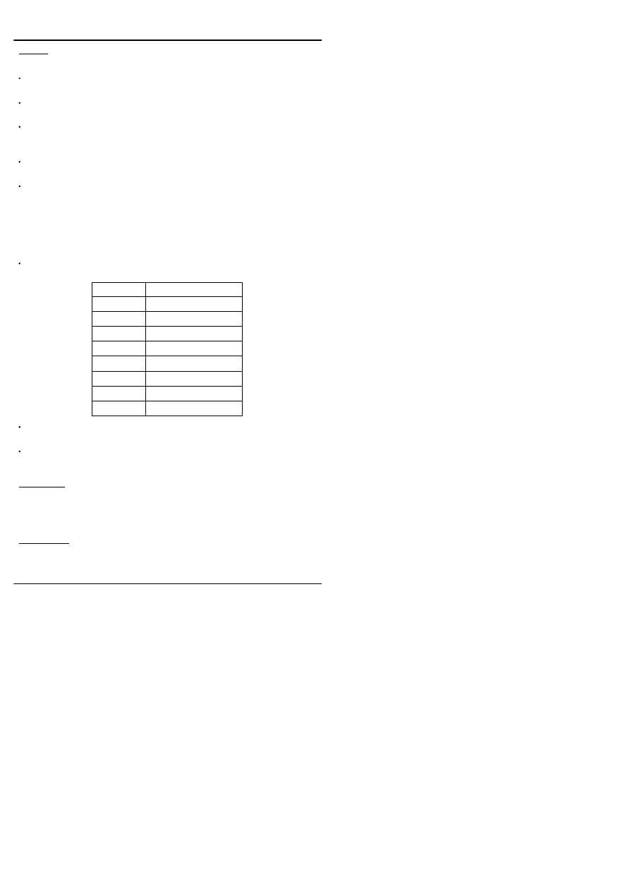
Rules
A UDP has one output and at least one input. Implementations may limit the
number of inputs, but at least 10 must be allowed.
If the UDP output is declared as a reg, the UDP is a sequential UDP.
Otherwise it is a combinational UDP.
If a sequential UDP output is initialized, the initial value only starts
propagating from the output of any instances of the primitive at the start of
simulation.
Sequential UDPs can be either level sensitive or edge sensitive. A sequential
UDP is edge sensitive if there is at least one edge indicator in the table.
The behaviour of a UDP is defined in a table. The rows in the table define the
output values for various input conditions. For a combinational UDP, each row
defines the output for one or more combinations of input values. For a
sequential UDP each row also takes into account the current value of the
output reg. A row may have at most one edge change entry. The row defines
the value of the output for the input and current output reg values, when the
specified edge occurs.
The special level and edge symbols used in tables have the following
meanings:
?
0 1 or X
b or B
0 or 1
-
Output is unchanged
(vw)
Change from v to w
r or R
(01)
f or F
(10)
p or P
(01) (0x) or (x1)
n or N
(10) (1x) or (x0)
*
(??)
Unspecified combinations of input values and edges result in the output being
unknown (1'bX).
The Z value is not supported. Zs on inputs are treated as Xs; Zs are not
allowed as output values. Note the special meaning of ?, which is different
from its meaning in a number (where it has the same meaning as Z).
Gotchas!
For a sequential UDP, if an edge appears anywhere in the table, all possible
edges on inputs must be considered, because the default is that an edge
causes the output to be unknown.
Synthesis
UDPs are not synthesizable by all tools.
104

Tips
UDPs can sometimes be made to simulate very efficiently compared with
behavioural models. Use UDPs when modelling library components such as
ASIC cells.
For components with more than one output, use a separate UDP for each
output.
Put a comment at the top of a table, indicating what the columns are.
Example
primitive Mux2to1 (f, a, b, sel);
//
Combinational UDP
output f;
input a, b, sel;
table
// a b sel : f
0 ? 0 : 0;
1 ? 0 : 1;
? 0 1 : 0;
? 1 1 : 1;
0 0 ? : 0;
1 1 ? : 1;
endtable
endprimitive
primitive Latch (Q, D, Ena);
output Q;
input D, Ena;
reg Q;
//
Level sensitive UDP
table
// D Ena : old Q : Q
0 0 : ? : 0;
1 0 : ? : 1;
? 1 : ? : -;
//
Keeps previous value
0 ? : 0 : 0;
1 ? : 1 : 1;
endtable
endprimitive
105

primitive DFF (Q, Clk, D);
output Q;
input Clk, D;
reg Q;
//
Edge sensitive UDP
initial
Q = 1;
table
// Clk D : old Q : Q
r 0 : ? : 0;
//
Clock '0'
r 1 : ? : 1;
//
Clock '1'
(0?) 0 : 0 : -;
//
Possible Clock
(0?) 1 : 1 : -;
//
" "
(?1) 0 : 0 : -;
//
" "
(?1) 1 : 1 : -;
//
" "
(?0) ? : ? : -;
//
Ignore falling clock
(1?) ? : ? : -;
//
" " "
? * : - : -;
//
Ignore changes on D
endtable
endprimitive
See Also
Module, Gate, Instantiation
106

A loop statement that repeats a statement or block of statements as long as a
controlling expression remains true (i.e. non-zero).
Syntax
while (
Expression
)
Statement
Where
See Statement.
Synthesis
Only synthesizable if the loop is ‘broken’ with a clock event control (E.g.
@(posedge Clock)).
Example
reg [15:0] Word;
while (Word)
begin
if (Word[0])
CountOnes = CountOnes + 1;
Word = Word >> 1;
end
See Also
For, Forever, Repeat
107
While

108

The
Verilog
Golden
Reference
Guide
Compiler Directives
109

Compiler directives are instructions to the Verilog compiler. Compiler
directives are preceded by the backwards apostrophe (`), sometimes called
the grave accent character.
The effect of a compiler directive starts from the place where it appears in the
source code, and continues through all files processed subsequently, to the
point where the directive is superseded, or the end of the last file to be
processed.
A summary of Verilog compiler directives follows. More detailed information
about some of the more important directives follows this summary.
Gotchas!
The effect of compiler directives may depend on the order in which the files
that include the source code for the design are compiled.
Standard Compiler Directives
The following compiler directives are defined in the Verilog LRM.
`celldefine and `endcelldefine
Used, respectively, before and after a module to tag it as a library cell. Cells
are used by certain PLI routines for applications such as delay calculators.
Example:
`celldefine
module Nand2 (...);
//
Nand2 is a ‘cell’
...
endmodule
`endcelldefine
`default_nettype
Changes the default net type for implicit declarations. If this directive is not
present, the default net type is wire.
Example:
`default_nettype tri1
//
All Verilog net types allowed
`define and `undef
`define defines a text macro. `undef cancels a macro definition.
Macros are substituted during the first phase of compilation. They are also
used to control conditional compilation (see `ifdef). For more details on
`define, see below.
110
Compiler Directives

`ifdef, `else and `endif
Conditionally compiles Verilog code, depending on whether or not a specified
macro is defined. For more details, see below.
`include
Directs the compiler to read the contents of a file, and compile them in place
of the `include directive.
Example:
`include "definitions.v"
`resetall
Resets all active compiler directives to their default values. This can be used
at the top of every Verilog source file, to prevent unwanted effects resulting
from compiler directives in files that were compiled before the file.
Example:
`resetall
`timescale
Defines the simulation time units and precision. For more details, see below.
`unconnected_drive and `nounconnected_drive
`unconnected_drive causes unconnected inputs of modules to pull up or
down. `nounconnected_drive resumes the default, which is to make
unconnected inputs float with a value of Z.
Example:
`unconnected_drive pull0
//
or ‘pull1
’
Non-Standard Compiler Directives
The following directives are not part of the IEEE standard, but are mentioned
in the LRM for informative purposes. They may not be supported by all
Verilog tools:
`default_decay_time
Specifies the default decay time for trireg nets, when no explicit decay time is
given.
Examples:
`default_decay_time 50
`default_decay_time infinite
//
Means it will not decay
111

`default_trireg_strength
Specifies the default strength for trireg nets, as an integer. The modelling of
strengths using integers is a non-standard extension to the Verilog language.
Example:
`default_trireg_strength 30
`delay_mode_distributed, `delay_mode_path, `delay_mode_unit and
`delay_mode_zero
These directives affect the way in which delays are simulated.
Distributed delays
are the delays on instances of primitives, continuous
assignments delays and net delays.
Path delays
are defined in specify
blocks.
Unit
and
zero
delays replace any distributed and path delays, and
may result in faster simulation, but at the expense of realistic delay
information.
By default a simulator will choose the longest of the distributed delays and
path delays.
112

`define defines a text macro. Macros are substituted in the first phase of
compilation. Macros can be used to improve the readability and
maintainability of the Verilog code where parameters or functions are
inappropriate, or where they are not allowed.
Syntax
{declaration}
`define Name[(Argument,...)]
Text
{usage}
`Name [(
Expression
,...)]
Where
Macros may be defined inside or outside modules.
Rules
Macro definitions, like all compiler directives, are active across file
boundaries, unless overridden by a subsequent `define, `undef or `resetall
directive. There are no scope restrictions.
When a macro is defined with arguments, the arguments may be used in the
macro text, and are substituted with the actual argument expressions when
the macro is used.
`define add(a,b) a + b
f = `add(1,2);
//
f = 1 + 2;
Macro definitions may span several lines, by escaping the intermediate
newlines with a backslash (\). The newlines are part of the macro text.
The macro text may not split the following language tokens: comments,
numbers, strings, names, reserved names, operators.
Compiler directives are not allowed as macro names.
Gotchas!
Macros with arguments are not supported by all implementations.
Once defined, a macro is used by prefacing the name with a backwards
apostrophe (`). The macro name without the apostrophe is a separate
identifier.
Be careful to distinguish the backwards apostrophe (`) from the inverted
comma (') which is used in numbers.
Do not end a macro definition with a semicolon, unless you really do want a
semicolon substituted when the macro is used. Otherwise you will probably
get a syntax error when the macro is used.
113
`define

Tips
Parameters are often preferable to macros for giving meaningful names to
literals.
Macros with arguments can usually be simulated more efficiently than
functions having the same functionality.
Example
This example shows how to use text macros to select different
implementations of modules in an hierarchical design. This is useful during
synthesis, when it may be necessary to simulate a mixture of RTL and
synthesized gates for a design.
`define SUBBLOCK1 subblock1_rtl
`define SUBBLOCK2 subblock2_rtl
`define SUBBLOCK3 subblock3_gates
module TopLevel ...
`SUBBLOCK1 sub1_inst (...);
`SUBBLOCK2 sub2_inst (...);
`SUBBLOCK3 sub3_inst (...);
...
endmodule
This example shows a text macro with arguments.
`define nand(delay) nand #(delay)
`nand(3) (f,a,b);
`nand(4) (g,f,c);
See Also
`ifdef
114

Conditionally compiles Verilog code, depending on whether or not a specified
macro is defined.
Syntax
`ifdef MacroName
VerilogCode
...
[`else
VerilogCode
...]
`endif
Where
Anywhere.
Rules
If the macro name has been defined using `define, the first block only of
Verilog code is compiled.
If the macro name is not defined, and an `else directive is present, the second
block only is compiled.
These directives may be nested.
Any code that is not compiled must still be valid Verilog code.
Tips
Can be used, for example, to switch between alternative implementations of a
module, or to selectively turn on the writing of diagnostic messages.
Example
`define primitiveModel
module Test;
...
`ifdef primitiveModel
MyDesign_primitives UUT (...);
`else
MyDesign_RTL UUT (...);
`endif
endmodule
See Also
`define
115
`ifdef

Defines the time units and simulation precision (smallest increment).
Syntax
`timescale
TimeUnit
/
PrecisionUnit
TimeUnit = Time Unit
PrecisionUnit = Time Unit
Time =
{either}
1 10 100
Unit =
{either}
s ms us ns ps fs
Where
<HERE>-module
Rules
The `timescale directive, like all compiler directives, affects all modules
compiled after the directive, whether in the same file, or in files that are
compiled separately, until the next `timescale or a `resetall directive.
The precision unit must be less than or equal to the time unit.
The precision for a simulation run is the smallest of all the precision units in
`timescale directives. All delays are rounded to the nearest precision unit.
Tips
Include a `timescale directive at the top of every module, even if there are no
delays in the module, because some simulators may require this.
Example
`timescale 10ns / 1ps
See Also
$timeformat
116
`timescale

The
Verilog
Golden
Reference
Guide
System Tasks and Functions
117

The Verilog language includes a number of useful system tasks and
functions. These can be enabled and called in the same way as user defined
tasks and functions. They are guaranteed to be available in any tool that
conforms to the IEEE Verilog standard. The Verilog LRM also mentions a
number of other, commonly found system tasks and functions, which are not
actually part of the standard, but may be found in some implementations.
Note that Verilog simulators from different vendors may include additional,
proprietary system tasks and functions, and users can add their own user
defined system tasks and functions using the Programming Language
Interface (PLI).
All system task and system function names, including user defined ones,
begin with a dollar character, to distinguish them from ordinary tasks and
functions.
There follows a summary of all the system tasks and functions mentioned in
the LRM. More detailed information for some of the more important of these
follows this summary.
Standard System Tasks And Functions
The following system tasks and functions are part of the IEEE standard.
$display, $monitor, $strobe, $write etc.
A whole family of system tasks to write text to the standard output or one or
more files. For full details see below.
$fopen and $fclose
$fopen("FileName");
{Returns an integer}
$fclose(
Mcd
);
$fopen is a system function to open a text file for writing. $fclose closes a file
that was opened with $fopen.
For full details, see below.
$readmemb and $readmemh
$readmemb("File",MemoryName[,
StartAddr
[,
FinishAddr
]]);
$readmemh("File",MemoryName[,
StartAddr
[,
FinishAddr
]]);
Tasks to initialize the contents of a memory array from a text file. For full
details, see below.
$timeformat
$timeformat[(
Units
,
Precision
,
Suffix
,
MinFieldWidth
)];
Defines the format for writing simulation time with $display etc. For full details,
see below.
118
System Tasks and Functions

$printtimescale
$printtimescale[(ModuleInstanceName]);
Displays the time unit and precision for a module in the following format:
Time scale of (module_name) is unit / precision.
If no argument is given, the time unit and precision for the module that called
$printtimescale are displayed.
$stop
$stop[(
N
)];
{N is 0, 1, or 2}
Causes simulation to suspend. The optional argument determines the type of
diagnostic output produced. 0 gives the least amount, 1 gives more, and 2
gives the most amount of output.
$finish
$finish[(
N
)];
{N is 0, 1, or 2}
Causes the simulator to exit, passing control back to the operating system. If
an argument is supplied, diagnostic messages are printed as follows:
0 - prints nothing
1 - prints simulation time and location (this is the default if no argument is
supplied).
2 - prints simulation time and location, and statistics about the memory and
CPU time used in the simulation.
$time, $stime, and $realtime
$time;
$stime;
$realtime;
System functions to return the current simulation time. The time returned has
the units of the module from which the system function was called, as defined
by `timescale.
$time returns a 64 bit unsigned value, rounded to the nearest unit.
$stime returns a 32 bit unsigned value, truncating large time values.
$realtime returns a real number.
Note that unlike any other functions in Verilog, these functions have no inputs.
$realtobits and $bitstoreal
$realtobits(
RealExpression
)
{returns a 64 bit value}
$bitstoreal(
BitValueExpression
)
{returns a real value}
Convert between a real number and a bit level representation, so that a real
number can be passed through the port of a module. (Ports are not allowed to
be declared as real). For an example, see Module.
119

$rtoi and $itor
$rtoi(
RealExpression)
{returns an integer}
$itor(
IntegerExpression)
{returns a real number}
Convert between a real number and an integer. $rtoi truncates the real
number to form the integer.
PLA Modelling Tasks
A number of system tasks are provided to model PLAs.
$async$and$array(MemoryName,{Inputs,...},{Outputs,...})
$async$nand$array(MemoryName,{Inputs,...},{Outputs,...})
$async$or$array(MemoryName,{Inputs,...},{Outputs,...})
$async$nor$array(MemoryName,{Inputs,...},{Outputs,...})
$async$and$plane(MemoryName,{Inputs,...},{Outputs,...})
$async$nand$plane(MemoryName,{Inputs,...},{Outputs,...})
$async$or$plane(MemoryName,{Inputs,...},{Outputs,...})
$async$nor$plane(MemoryName,{Inputs,...},{Outputs,...})
$sync$and$array(MemoryName,{Inputs,...},{Outputs,...})
$sync$nand$array(MemoryName,{Inputs,...},{Outputs,...})
$sync$or$array(MemoryName,{Inputs,...},{Outputs,...})
$sync$nor$array(MemoryName,{Inputs,...},{Outputs,...})
$sync$and$plane(MemoryName,{Inputs,...},{Outputs,...})
$sync$nand$plane(MemoryName,{Inputs,...},{Outputs,...})
$sync$or$plane(MemoryName,{Inputs,...},{Outputs,...})
$sync$nor$plane(MemoryName,{Inputs,...},{Outputs,...})
The first argument of each of these tasks is the name of a memory array,
which stores the personality of the PLA being modelled. The array should be
declared with ascending indices (E.g. reg [1:NInputs] Mem[1:NOutputs]). The
personality can be changed dynamically.
The asynchronous tasks are analogous to procedural continuous
assignments. The outputs are updated whenever one of the inputs changes,
or if the personality is changed. The synchronous tasks only update the
outputs when the task is called.
Tasks for Stochastic Modelling
$q_initialize(
q
_
id
,
q
_
type
,
max
_
length
,
status
);
$q_add(
q_id
,
job_id
,
inform_id
,
status
);
$q_remove(
q_id
,
job_id
,
inform_id
,
status
);
$q_full(
q_id
,
status
);
{Returns an integer}
$q_exam(
q_id
,
q_stat_code
,
q_stat_value
,
status
);
Four system tasks and a system function to support stochastic modelling by
enabling the creation and management of queues. For full details, see below.
120

Random Number Generation Functions
$random[(
Seed
)];
$dist_chi_square(
Seed
,
DegreeOfFreedom
);
$dist_erlang(
Seed
, K_
stage
,
Mean
);
$dist_exponential(
Seed
,
Mean
);
$dist_normal(
Seed
,
Mean
,
StandardDeviation
);
$dist_poisson(
Seed
,
Mean
);
$dist_t(
Seed
,
DegreeOfFreedom
);
$dist_uniform(
Seed
,
Start
,
End
);
Each of these system functions, when called repeatedly, returns a sequence
of pseudo random numbers, according to various probability distributions. The
sequence will always be the same for the same starting seed.
Consult a text on statistics or probability theory for details of the distribution
functions and their application.
Specify Block Timing Checks
$hold(
ReferenceEvent
,
DataEvent
,
Limit
[,
Notifier
]);
$nochange(
ReferenceEvent
,
DataEvent
,
StartEdgeOffset
,
EndEdgeOffset
[,
Notifier
]);
$period(
ReferenceEvent
,
Limit
[,
Notifier
]);
$recovery(
ReferenceEvent
,
DataEvent
,
Limit
[,
Notifier
]);
$setup(
DataEvent
,
ReferenceEvent
,
Limit
[,
Notifier
]);
$setuphold(
ReferenceEvent
,
DataEvent
,
SetupLimit
,
HoldLimit
[,
Notifier
]);
$skew(
ReferenceEvent
,
DataEvent
,
Limit
[,
Notifier
]);
$width(
ReferenceEvent
,
Limit
[,
Threshold
[,
Notifier
]]);
Special system tasks to perform common timing checks. These system tasks
may only be called from specify blocks. For full details, see below.
Value Change Dump Tasks
$dumpfile("FileName");
$dumpvars[(
Levels
, ModuleOrVariable,...)];
$dumpoff;
$dumpon;
$dumpall;
$dumplimit(
FileSize
);
$dumpflush;
A family of system tasks to store value changes in a Value Change Dump
(VCD) file. A VCD file is a means of passing simulation stimulus or results to
another program, for example a graphical waveform viewer. For full details,
see below.
121

Non-Standard System Tasks And Functions
The following system tasks and functions are mentioned in the LRM, but are
not part of the IEEE standard.
Some of these tasks and functions concern the “interactive mode” of a Verilog
simulator. If a simulator supports an interactive mode of operation, it may
accept these tasks and functions as commands.
$countdrivers
$countdrivers(
Net
, [
IsForced
,
NoOfDrivers
,
NoOfDriversTo0
,
NoOfDriversTo1
,
NoOfDriversToX
]);
System function to show the number of drivers on a specified scalar net or bit
select of a vector net. Drivers include outputs of primitives and continuous
assignments, but not an active force. $countdrivers returns 0 if the net has
more than one driver, and 1 otherwise. All the arguments, except the first,
return integer values.
IsForced
returns 1 if the net is forced, and 0 otherwise.
NoOfDrivers
returns the number of drivers.
The remaining arguments return values which add up to
NoOfDrivers
.
$list
$list[(
ModuleInstance
)];
Called interactively to list the source code for the current scope, or a specified
scope in the design.
$input
$input("FileName");
Reads interactive commands from a text file.
$scope and $showscopes
$scope(
ModuleInstance
);
$showscopes[(
N
)];
Interactive commands to set the current scope and show the scopes in the
current scope, and below (if
N
is present, and is non-zero).
$key, $nokey, $log and $nolog
$key[("FileName")];
$nokey;
$log[("FileName")];
$nolog;
The “key” file records commands that are entered interactively. The “log” file
records all messages that are written to the standard output during a
simulation run.
$nokey and $nolog disable recording. With no argument, $key and $log
re-enable recording. With a file name argument, they create new files.
122

$reset, $reset_count and $reset_value
$reset[(
StopValue
[,
ResetValue
[,
DiagnosticsValue
]]);
$reset_count;
{Returns an integer}
$reset_value;
{Returns an integer}
$reset resets a simulator so that simulation can restart from the beginning.
A
StopValue
of 0 means that the simulator resets in its interactive mode,
allowing the user to start and control simulation. A non-zero value means
that simulation will automatically restart from the beginning.
ResetValue
can be read by the $reset_value function.
DiagnosticsValue
specifies the kind of messages the tool displays before
resetting.
$reset_count returns the number of times $reset has been called.
$reset_value returns the value passed to $reset.
$save, $restart and $incsave
$save("FileName");
$incave("FileName");
$restart("FileName");
$save saves the complete state of the simulation to a file, so that it can be
read using $restart.
$incsave saves only what has changed since the last call to $save.
$restart resets the simulation from a full or incremental save file. For an
incremental save, the previous full save file must be present: it is referenced
in the incremental save file.
$showvars
$showvars[(
NetOrRegister
,...)];
Displays the status of nets and registers on the standard output. This task is
used interactively. The status information displayed is not defined in the LRM.
It might include the current values of nets and registers, any scheduled
events on those nets and registers, and the drivers of the nets.
If no list of variables is given, information is displayed for all the nets and
registers in the current scope.
$getpattern
$getpattern(
MemoryElement
);
$getpattern is a system function which may only be used in a continuous
assignment. The left hand side of the continuous assignment must be a
concatenation of scalar nets. $getpattern is used together with $readmemb
and $readmemh to apply test vectors from a text file. $getpattern provides
fast processing when there are large numbers of scalar inputs involved.
123

$sreadmemb and $sreadmemh
$sreadmemb(Memory,
StartAddr, FinishAddr, String, ...
);
$sreadmemh(Memory,
StartAddr, FinishAddr, String, ...
);
These tasks are similar to $readmemb and $readmemh, except that the
memory is initialized from data supplied in one or more character strings
rather than from files. The format of the character strings is the same as that
of the corresponding text files for $readmemb and $readmemh.
$scale
$scale(DelayName);
{Returns realtime}
Converts a time value in one module to the time units of the module from
which $scale is called. $scale takes a hierarchical reference to a delay value,
such as a parameter in another module, and scales it to the time units of the
module from which it was called.
124
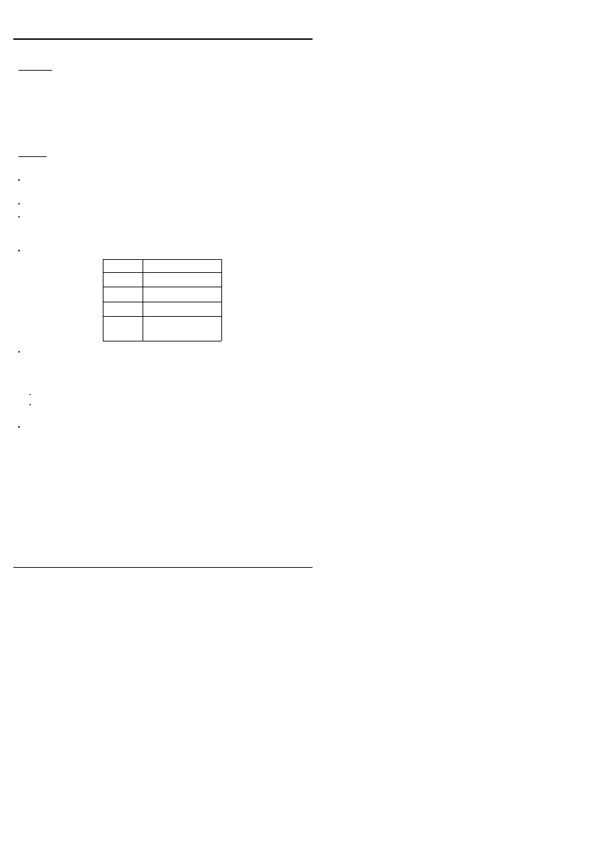
Writes formatted text to the standard output and the simulator log, or to a file.
Syntax
$display(
Argument,...
);
$fdisplay(
Mcd, Argument,...
);
$write(
Argument,...
);
$fwrite(
Mcd, Argument,...
);
Mcd = Expression
{Integer value}
Rules
The only difference between $display and $write, is that $display writes out a
newline character at the end of the text, whereas $write does not.
Arguments may be strings or expressions, or blank (two adjacent commas).
Strings to be written may contain format specifiers (see below). If so, each
string must be followed by enough expressions to provide values for all the
format specifiers in the string (except %m).
Strings may also include the following escaped characters:
\n
Newline
\t
Tab
\"
Double quote
\\
Back slash
\nnn
ASCII value of
character (octal)
Unknown and high impedance values are written as follows. Note that for
octal and hexadecimal numbers, one digit represents either 3 or 4 bits,
respectively. For decimal numbers, unknown and high impedance values are
written as one digit.
Lower-case x or z means all the bits represented by the digit are unknown.
Upper-case X or Z means that some, but not all, of the bits represented by
the digit are unknown.
If an argument list contains two adjacent commas, a space is written out at
that point.
125
$display and $write

Format Specifiers
The following format specifiers are allowed in strings:
%b %B
Binary
%o %O
Octal
$d $D
Decimal
%h %H
Hexadecimal
%e %E %f %F %g %G
Real
%c %C
Character
%s %S
String
%v %V
Binary and Strength
%t %T
Time
%m %M
Hierarchical Instance
%v prints strengths as follows: supply - Su, strong - St, Pull - Pu, Large - La,
Weak - We, Medium - Me, Small - Sm, Highz - Hi. %v also prints the values H
and L (these are printed as X with %b)
A minimum field width value may be included after the % character (E.g.
%10d). For decimal numbers, leading zeroes are replaced by spaces, but for
other radixes, the leading zeroes are printed. A minimum field width of 0
means that the field will always be just big enough to display the value.
The format specifiers for real numbers (%e, %f and %g) have the full
formatting capabilities available in the C programming language. For example
%10.3g specifies a minimum field width of 10, with 3 digits following the
decimal point.
Expressions that are not written using a format specifier are written in decimal
format. There are additional tasks which have different default formats, for
example $displayb, $fwriteo and $displayh write out numerical expressions as
binary, octal and hex values respectively when a format specifier is not used.
Example
$display("Illegal opcode %h in %m at %t",
Opcode, $realtime);
$writeh("Register values (hex.): ",
reg1,, reg2,, reg3,, reg4,"\n");
See Also
$monitor, $strobe
126

$fopen is a system function to open a file for writing, and $fclose is a system
task to close a file. Text is written to the files using the system tasks
$fdisplay, $fmonitor etc.
Syntax
$fopen("FileName");
{Returns an integer}
$fclose(
Mcd
);
Mcd
=
Expression
{Integer value}
Where
See Statement;
Rules
Up to 32 files may be opened at once, although the maximum may be lower,
depending on the operating system.
When the function $fopen is called, it returns a 32-bit unsigned multichannel
descriptor that is associated with the file, or 0 if the file could not be opened
for writing.
The multichannel descriptor can be thought of as 32 flags, each representing
a separate file (channel). Bit 0 is associated with the standard output, bit 1
with the first opened file, bit 2 with the second opened file etc. When a file
output system task such as $fdisplay is called, the first argument is a
multichannel descriptor, which specifies where to write the text. The text is
written in each file whose flag is set in the multichannel descriptor.
Example
integer MessagesFile, DiagnosticsFile, AllFiles;
initial
begin
MessagesFile = $fopen("messages.txt");
if (!MessagesFile)
begin
$display("Could not open \"messages.txt\"");
$finish;
end
DiagnosticsFile = $fopen("diagnostics.txt");
if (!DiagnosticsFile)
begin
$display("Could not open \"diagnostics.txt\"");
$finish;
end
AllFiles = MessagesFile | DiagnosticsFile | 1;
127
$fopen and $fclose

$fdisplay(AllFiles, "Starting simulation ...");
$fdisplay(MessagesFile, "Messages from %m");
$fdisplay(DiagnosticsFile, "Diagnostics from %m");
...
$fclose(MessagesFile);
$fclose(DiagnosticsFile);
end
See Also
$display, $monitor, $strobe
128

Writes out a line of text whenever one or more of a specified list of nets or
registers changes value. Used in test fixtures to monitor simulated behaviour.
Syntax
$monitor(
Argument,...
);
$fmonitor(
Mcd, Argument,...
);
$monitoron;
{turns monitor flag on}
$monitoroff;
{turns monitor flag off}
Mcd = Expression
{Integer value}
Rules
The syntax of the arguments to these system tasks and the text they write is
exactly the same as for the equivalent $display tasks.
Only one $monitor process, and any number of $fmonitor processes can be
running simultaneously.
A second or subsequent call to $monitor cancels any existing $monitor
process, and replaces it with a new $monitor process.
$monitoroff disables monitoring, $monitoron re-enables monitoring.
$monitoron produces a display immediately, based on the current $monitor
process, and whether or not a value change has taken place.
There is no $fmonitor equivalent to $monitoron and $monitoroff
The system functions $time, $stime and $realtime do not trigger a line of
display from $monitor etc. or $fmonitor etc.
Tips
Use $monitor in test fixtures for obtaining simulation results from any
compliant Verilog simulator. Tasks used to create graphical displays of
waveforms are usually simulator dependent.
Example
initial
$monitor("%t : a = %b, f = %b", $realtime, a, f);
See Also
$display, $strobe, $fopen
129
$monitor etc.

Initializes a memory array with values from a text file. The contents of the text
file may be in binary format (for $readmemb) or hexadecimal format (for
$readmemh)
Syntax
{System task call}
$readmemb("File",MemoryName[,
StartAddr
[,
FinishAddr
]]);
$readmemh("File",MemoryName[,
StartAddr
[,
FinishAddr
]]);
{Text file}
{either}
WhiteSpace DataValue
@
Address
WhiteSpace
=
{either}
Space Tab Newline Formfeed
DataValue
=
{either}
BinaryDigit
...
{$readmemb}
HexDigit
...
{$readmemh}
Address
=
HexDigit
...
Rules
The first argument is the name of an ASCII file. The file may contain only
white space, Verilog comments, (hex) address values and binary or hex data.
The second argument is the name of a memory array.
Data values must be the same width as the memory array, and be separated
by white space. They are read into successive memory locations, starting at
the start of the array, or the start address, if specified. Data values continue to
be read until the end of the file or the end address, if specified, is reached.
Address values are hexadecimal numbers (even for $readmemb) preceded
by @. When an address value is encountered, the next data word is read into
that address.
Synthesis
Not synthesizable. Their effect is ignored by synthesis tools. Flip-flops
inferred from memory arrays will not be initialized in the synthesized design; if
a power up reset is required, this must be coded explicitly.
Tips
Memory arrays can be used to store stimulus, which is read from a text file.
This is the only way to read data into a Verilog simulation, without extending
the language using the Programming Language Interface (PLI) or using
non-standard language extensions.
Example
module Test;
reg a,b,c,d;
130
$readmemb and $readmemh

parameter NumPatterns = 100;
integer Pattern;
reg [3:0] Stimulus[1:NumPatterns];
MyDesign UUT (a,b,c,d,f);
initial
begin
$readmemb("Stimulus.txt", Stimulus);
Pattern = 0;
repeat (NumPatterns)
begin
Pattern = Pattern + 1;
{a,b,c,d} = Stimulus[Pattern];
#110;
end
end
initial
$monitor("%t a=%b b=%b c=%b =%b : f=%b",
$realtime, a, b, c, d, f);
endmodule
131

Prints a formatted line of text at the end of a time step, once all events at that
time have been processed.
Syntax
$strobe(
Argument,...
);
$fstrobe(
Mcd, Argument,...
);
Mcd = Expression
{Integer value}
Rules
The syntax of the arguments to these system tasks and the text they write is
exactly the same as for the equivalent $display tasks.
$strobe only prints the text when all activity at the time at which it was called
has completed. This includes the effects of all blocking and non-blocking
assignments.
Tips
Use $strobe in preference to $display or $write when writing simulation
results. This guarantees that the steady values of the strobed nets and
registers will be written.
Example
initial
begin
a = 0;
$display(a);
//
displays 0
$strobe(a);
//
displays 1 ...
a = 1;
//
... because of this statement
end
See Also
$display, $monitor, $write
132
$strobe

Defines the format for printing simulation time. $timeformat is used in
conjunction with the format specifier %t.
Syntax
$timeformat[(
Units
,
Precision
,
Suffix
,
MinFieldWidth
)];
Rules
Units
is an integer between 0 and -15 which indicates the units in which times
are to be printed: 0 means seconds, -3 means milliseconds, -6 microseconds,
-9 nanoseconds, -12 picoseconds and -15 femtoseconds. Intermediate values
may also be used: for example -10 means 100 ps units.
Precision
is the number of decimal digits to be printed after the decimal point.
Suffix
is a string that is printed after the time value.
MinFieldWidth
is the minimum number of characters to be printed, including
leading spaces. If more characters are required, more will be printed.
The defaults, if no arguments are specified, are as follows. Units:the
simulation precision; Precision: 0; Suffix: null string; MinFieldWidth: 20
characters.
Tips
Use `timescale, $timeformat and $realtime (with %t) to specify and display
simulation times using $display, $monitor, or one of the other display tasks.
Example
$timeformat(-10, 2, " x100ps", 20);
//
20.12 x100ps
See Also
`timescale, $display
133
$timeformat
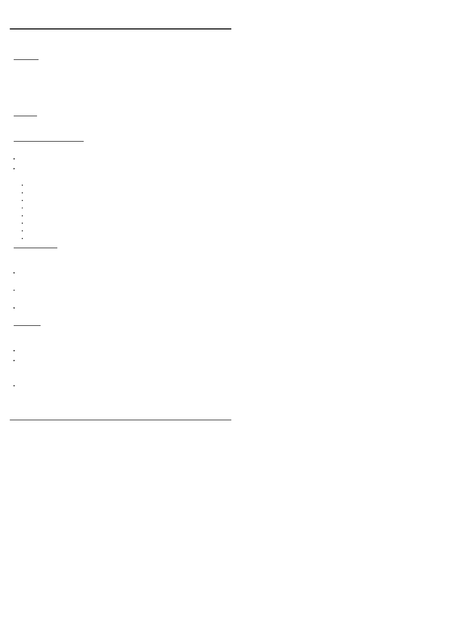
Verilog provides a set of system tasks and functions to support stochastic
modelling by enabling the creation and management of queues.
Syntax
$q_initialize(
q_id, q_type, max_length, status
);
$q_add(
q_id, job_id, inform_id, status
);
$q_remove(
q_id, job_id, inform_id, status
);
$q_full(
q_id, status
);
{Returns an integer}
$q_exam(
q_id, q_stat_code, q_stat_value, status
);
Where
See Statement.
General Comments
All arguments to these system tasks and functions are integers.
Each of these system tasks and functions returns a status integer, which has
one of the following values:
0 - Okay
1 - The queue is full: can’t add the job ($q_add)
2 - Undefined q_id
3 - The queue is empty: can’t remove the job ($q_remove)
4 - Unsupported queue type: can’t create the queue ($q_initialize)
5 - Maximum length is zero or less: can’t create the queue ($q_initialize)
6 - Duplicate q_id: can’t create the queue ($q_initialize)
7 - Insufficient memory: can’t create the queue ($q_initialize)
$q_initialize
Creates a queue.
q_id (output) is a unique queue identifier, which is used to refer to that queue
when calling the other queue tasks and functions.
q_type (input) is either 1 for a first-in, first-out (FIFO), or 2 for last-in, first-out
(LIFO) queue.
max_length (input) is the maximum number of entries that are allowed in the
queue.
$q_add
Adds an entry to a queue.
q_id (input) indicates to which queue to add the entry.
job_id (input) identifies the job. This is usually an integer that is incremented
by the user each time an element is added to the queue, and can be used to
identify the element when it is removed.
inform_id (input) is used to associate information with the queue entry. Its
meaning is user defined.
134
Stochastic Modelling

$q_remove
Gets an entry from a queue.
q_id (input) indicates from which queue to remove the entry.
job_id (output) identifies the job (see $q_add).
inform_id (output) is the value stored by $q_add.
$q_full
Checks to see if a queue is full. The returned value is 1 when the queue is
full, and 0 when it is not.
$q_exam
Requests statistics about a queue. The times referred to in the following
descriptions are based on when elements are added to the queue (arrival
time), and the difference in time between when an element was added and
when it was removed (wait time). The unit of time is the simulation precision.
q_stat_code (input) indicates the information requested:
1 - Current queue length
2 - Mean inter-arrival time
3 - Maximum queue length
4 - Shortest wait time ever
5 - Longest wait time for jobs still in the queue
6 - Average wait time in the queue.
q_stat_value (output) returns the requested information.
135

Example
module Queues;
parameter Queue = 1;
//
Q_id
parameter Fifo = 1, Lifo = 2;
parameter QueueMaxLen = 8;
integer Status, Code, Job, Value, Info;
reg IsFull;
task Error;
//
Write error message and quit
...
endtask
initial
begin
//
Create the queue
$q_initialize(Queue, Lifo, QueueMaxLen, Status);
if ( Status )
Error("Couldn't initialize the queue");
//
Add jobs
for (Job = 1; Job <= QueueMaxLen; Job = Job + 1)
begin
#10 Info = Job + 100;
$q_add(Queue, Job, Info, Status);
if ( Status )
Error("Couldn't add to the queue");
$display("Added Job %0d, Info = %0d", Job, Info);
$write("Statistics: ");
for ( Code = 1; Code <= 6; Code = Code + 1 )
begin
$q_exam(Queue, Code, Value, Status);
if ( Status )
Error("Couldn't examine the queue");
$write("%8d", Value);
end
$display("");
end
//
Queue should now be full
IsFull = $q_full(Queue, Status);
if ( Status )
Error("Couldn't see if queue is full");
if ( !IsFull )
136

Error("Queue is NOT full");
//
Remove jobs
repeat ( 10 ) begin
#5 $q_remove(Queue, Job, Info, Status);
if ( Status )
Error("Couldn't remove from the queue");
$display("Removed Job %0d, Info = %0d", Job,Info);
$write("Statistics: ");
for ( Code = 1; Code <= 6; Code = Code + 1 )
begin
$q_exam(Queue, Code, Value, Status);
if ( Status )
Error("Couldn't examine the queue");
$write("%8d", Value);
end
$display("");
end
end
endmodule
See Also
$random, $dist_chi_square etc.
137

Verilog provides a number of system tasks, called only from specify blocks, to
perform common timing checks.
Syntax
$hold(
ReferenceEvent
,
DataEvent
,
Limit
[,
Notifier
]);
$nochange(
ReferenceEvent
,
DataEvent
,
StartEdgeOffset
,
EndEdgeOffset
[,
Notifier
]);
$period(
ReferenceEvent
,
Limit
[,
Notifier
]);
$recovery(
ReferenceEvent
,
DataEvent
,
Limit
[,
Notifier
]);
$setup(
DataEvent
,
ReferenceEvent
,
Limit
[,
Notifier
]);
$setuphold(
ReferenceEvent
,
DataEvent
,
SetupLimit
,
HoldLimit
[,
Notifier
]);
$skew(
ReferenceEvent
,
DataEvent
,
Limit
[,
Notifier
]);
$width(
ReferenceEvent
,
Limit
[,
Threshold
[,
Notifier
]]);
ReferenceEvent
=
EventControl
PortName
[&&&
Condition
]
DataEvent
= PortName
Limit
=
{either}
ConstantExpression
SpecparamName
Threshold
=
{either}
ConstantExpression
SpecparamName
EventControl =
{either}
posedge
negedge
edge [
TransitionPair,...
]
TransitionPair =
{either}
01 0x 10 1x x0 x1
Condition
=
{either}
ScalarExpression
~
ScalarExpression
ScalarExpression
==
ScalarConstant
ScalarExpression
===
ScalarConstant
ScalarExpression
!=
ScalarConstant
ScalarExpression
!==
ScalarConstant
Rules
A transition on the reference event establishes the reference time for the
timing check. Reference events must be referenced to a module input or
inout.
A transition on the data event initiates the timing check. Data events must be
referenced to a module input or inout.
No setup violation is reported when the reference event and data event are
simultaneous. However, a hold violation is reported.
For $width, pulses shorter than the threshold (if given) will not produce
violations.
The reference event for the following time checks must be an edge triggered
statement: $width, $period, $recovery, $nochange.
Reference events may use the keyword edge, except for $recovery and
$nochange, where only posedge and negedge are allowed.
138
Timing Checks

Conditional timing checks (using the &&& notation) are made only if the
condition is true.
The notifier argument, if present, must be a register. The value of the register
changes when a violation occurs. If it was X it becomes 0, if 0 then 1, and if 1
then 0. If the value is Z it does not change.
Gotchas!
Note that these system tasks can only be called in specify blocks. They
cannot be called as procedural statements.
The order of the ReferenceEvent and DataEvent arguments is reversed for
$setup!
Tips
For a complex condition, describe the condition outside the specify block, and
drive a conditioning signal (wire or reg) to be used inside the specify block.
Example
reg Err, FastClock;
//
Notifier registers
specify
specparam Tsetup = 3.5, Thold = 1.5,
Trecover = 2.0, Tskew = 2.0,
Tpulse = 10.5, Tspike = 0.5;
$hold(posedge Clk, Data, Thold);
$nochange(posedge Clock, Data, 0, 0 );
$period(posedge Clk, 20, FastClock]);
$recovery(posedge Clk, Rst, Trecover);
$setup(Data, posedge Clk, Tsetup);
$setuphold(posedge Clk &&& !Reset, Data,
Tsetup, Thold, Err);
$skew(posedge Clk1, posedge Clk2, Tskew);
$width(negedge Clk, Tpulse, Tspike);
endspecify
See Also
Specify, Specparam
139

A family of system tasks to store value changes in a Value Change Dump
(VCD) file. A VCD file is a means of passing simulation stimulus or results to
another program, for example a graphical waveform viewer.
Syntax
$dumpfile("FileName");
$dumpvars[(
Levels
, ModuleOrVariable,...)];
$dumpoff;
{suspend dumping}
$dumpon;
{resume dumping}
$dumpall;
{dump a checkpoint}
$dumplimit(
FileSize
);
$dumpflush;
{update the dump file}
Where
See Statement.
Rules
Levels is the number of levels of hierarchy to dump for any specified modules,
with 1 meaning the specified levels of hierarchy only, and 0 meaning the
specified levels, and all instances below.
If no arguments are given, all the variables in the design are dumped.
FileSize is the maximum dump file size, in bytes.
$dumpvars may be called more than once, but each call must be at the same
time (usually the start of simulation).
Example
module Test;
...
initial
begin
$dumpfile("results.vcd");
$dumpvars(1, Test);
end
//
Perform periodic checkpointing of the design.
initial
forever
#10000 $dumpall;
endmodule
140
Value Change Dump

The
Verilog
Golden
Reference
Guide
Command Line Options
141

Whilst the command line options used when invoking Verilog simulators are
not part of the Verilog language, and are not mentioned in the LRM, most
Verilog simulators support a common set of command line options, as well as
their own proprietary ones.
There are two sorts of command line option, UNIX command options, which
are one character preceded by a minus sign (E.g. -s), and ‘plus arguments’,
which are of the form +word. Some of the UNIX command line options are
followed by a value, such as a file name (E.g. -f file).
These are the most useful of the commonly found command line options.
Note that not all simulators will support these options.
-f
CommandFile
- read further command line options from
CommandFile
, as
well as from the command line.
-k
KeyFile
- Record any interactive commands entered during simulation in
the file
KeyFile
.
-l
LogFile
- Record simulator messages in
LogFile
(including output from
$display etc.), as well as the standard output.
-r
SaveFile
- Restart simulation from a file that was created by the
(non-standard) system task $save.
-s - Interrupt the simulator at time 0. This allows simulation to be controlled
interactively.
-u - Treat Verilog source code as consisting entirely of upper-case
characters, except for strings. Use this option with care.
-v
LibraryFile
- Search for missing modules or UDPs in
LibraryFile.
Only
modules or UDPs that are instanced, but not defined in the rest of the design
are compiled from
LibraryFile
. Modules and UDPs that are not used in the
design are not compiled.
-y
LibraryDirectory
- Search for missing modules or UDPs in files in
LibraryDirectory
. A module is expected to be defined in a file in the library
directory having the same name as the module. If the command line option
+libext+
extension
is given, it specifies the file extension that is appended to
the module name to get the file name. For example, -y mylib +libext+.v means
look for a missing module ‘mycell’ in the file mylib/mycell.v
+define+
MacroName
- Defines the text macro
MacroName
, with a null value.
Such macros can be used in `ifdef statements.
+incdir+
Directory
[+
Directory...
] - Defines a search list of directories in which
to search for files to be included with `include. The search starts in the current
directory, and if the include file is not found there, the search continues
through the +incdir directories in order.
+libext+
Extension
- Defines the library file extension. See -y above.
+notimingchecks - Turn off timing checks in specify blocks. This may speed
up simulation, or suppress spurious timing error messages. Use with care.
+mindelays, +typdelays, +maxdelays - Use, respectively, minimum, typical
or maximum delays throughout the design. The default is to use typical
142
Command Line Options

delays. You cannot mix minimum, typical and maximum delays in the same
simulation run.
Gotchas!
Verilog simulators cannot check for misspelled ‘plus’ arguments. This is
because the user can define his own ‘plus’ arguments. Therefore you must be
extra careful to spell options such as “+maxdelays” correctly.
143

Always
12
And
Gate
42
Argument
Function
39
Task
94
`define
113
Assign
Continuous Assignment
21
Procedural Continuous
Assignment
77
Assignment
Procedural Assignment
74
Continuous Assignment
21
Procedural Continuous
Assignment
77
Begin
14
Bit Select
Expression
31
Blocking Assignment
Procedural Assignment
74
Block
Begin
14
Fork
38
Buf
Gate
42
Bufif0
Gate
42
Bufif1
Gate
42
Case
16
Casex
Case
16
Casez
Case
16
Clock Skew
Procedural Assignment
74
Cmos
Gate
42
Coding Standards
18
Command Line Options
142
Comment
20
Compiler Directives
110
Continuous Assignment
21
Deassign
Continuous Assignment
21
Decay Time
Delay
24
Net
60
Declaration
Event
29
Function
39
Net
60
Register
80
Task
94
Default
Case
16
Defparam
23
Delay
24
Delay Control
Timing Control
100
Design Flow
26
Disable
27
Drive Strength
Strength
90
Net
60
Continuous Assignment
21
Driver
Net
60
Procedural Assignment
74
Else
If
47
End
Begin
14
Endcase
Case
16
Errors
28
Escaped Identifier
Name
57
Event
29
Event Control
Timing Control
100
Event Trigger
Event
29
Expansion
Net
60
Expression
31
For
33
Force
35
Index

Forever
37
Fork
38
Function
39
Function Call
41
Gate
42
Hierarchical Name
Name
57
Hierarchy
Instantiation
51
Module
54
Name
57
Identifier
Name
57
Reserved Words
83
IEEE 1364
46
If
47
Implicit Declaration
Net
60
Instantiation
51
Incomplete Assignment
If
47
Case
16
Inertial Delay
PATHPULSE$
71
Initial
49
Inout
Port
72
Task
94
Input
Port
72
Task
94
User Defined Primitive
103
Instantiation
51
Integer
Register
80
Join
Fork
38
Label
Case
16
Begin
14
Fork
38
Loop
For
33
Forever
37
Repeat
82
While
107
Macro
`define
113
Macromodule
Module
54
Memory
Register
80
MinTypMaxExpression
Expression
31
Module
54
Name
57
Named Block
Begin
14
Fork
38
Disable
27
Named Event
Event
29
Nand
Gate
42
Net
60
Nmos
Gate
42
Non-Blocking Assignment
Procedural Assignment
74
Nor
Gate
42
Not
Gate
42
Notif0
Gate
42
Notif1
Gate
42
Number
63
Operators
66
Or
Gate
42
Output
Port
72
Task
94
Function
39
User Defined Primitive
103
Overriding Parameters
Defparam
23
Instantiation
51
Index

Parallel Block
Fork
38
Parameter
69
Part Select
Expression
31
Path Delay
Specify
84
PATHPULSE$
71
PLA
System Tasks And
Functions
118
PLI
Programming Language
Interface
79
Pmos
Gate
42
Port
72
Precision
`timescale
116
Primitive
Gate
42
User Defined Primitive
103
Procedural Block
Initial
49
Always
12
Procedural Assignment
74
Procedural Continuous
Assignment
77
Programming Language
Interface
79
Pulldown
Gate
42
Pullup
Gate
42
Pulse
PATHPULSE$
71
Rcmos
Gate
42
Real
Register
80
Realtime
Register
80
Reg
Register
80
Register
80
Release
Force
35
Repeat
82
Repeat Control
Timing Control
100
Reserved Words
83
Rnmos
Gate
42
Rpmos
Gate
42
Rtran
Gate
42
Rtranif0
Gate
42
Rtranif1
Gate
42
Scalared
Net
60
SDPD
Specify
84
Sensitivity List
Timing Control
100
Always
12
Sequential Block
Begin
14
Specify
84
Specparam
88
Statement
89
Stochastic Modelling
134
Strength
90
String
92
Supply0
Net
60
Supply1
Net
60
Synthesizable Templates
Always
12
System Tasks And
Functions
118
Table
User Defined Primitive
103
Task
94
Task Enable
98
Index

Text Macro
`define
113
Time
Register
80
Timing Checks
138
Timing Control
100
Tran
Gate
42
Tranif0
Gate
42
Tranif1
Gate
42
Transport Delay
PATHPULSE$
71
Tri
Net
60
Tri0
Net
60
Tri1
Net
60
Triand
Net
60
Trior
Net
60
Trireg
Net
60
UDP
User Defined Primitive
103
Unsigned Number
Number
63
Upwards Name Reference
Name
57
User Defined Primitive
103
Value Change Dump
140
VCD
Value Change Dump
140
Vectored
Net
60
Wait Control
Timing Control
100
Wand
Net
60
While
107
White Space
Name
57
Wire
Net
60
Wor
Net
60
Xnor
Gate
42
Xor
Gate
42
`celldefine
Compiler Directives
110
`default_decay_time
Compiler Directives
110
`default_nettype
Compiler Directives
110
`default_trireg_strength
Compiler Directives
110
`define
113
`delay_mode_distributed
Compiler Directives
110
`delay_mode_path
Compiler Directives
110
`delay_mode_unit
Compiler Directives
110
`delay_mode_zero
Compiler Directives
110
`else
`ifdef
115
`endcelldefine
Compiler Directives
110
`endif
`ifdef
115
`ifdef
115
`include
Compiler Directives
110
`nounconnected_drive
Compiler Directives
110
`resetall
Compiler Directives
110
`timescale
116
`unconnected_drive
Compiler Directives
110
`undef
Compiler Directives
110
Index

$async$and$array Etc.
System Tasks And
Functions
118
$bitstoreal
System Tasks And
Functions
118
$countdrivers
System Tasks And
Functions
118
$display And $write
125
$dist_chi_square
System Tasks And
Functions
118
$dist_erlang
System Tasks And
Functions
118
$dist_exponential
System Tasks And
Functions
118
$dist_normal
System Tasks And
Functions
118
$dist_poisson
System Tasks And
Functions
118
$dist_t
System Tasks And
Functions
118
$dist_uniform
System Tasks And
Functions
118
$dumpall
System Tasks And
Functions
118
$dumpfile
System Tasks And
Functions
118
$dumplimit
System Tasks And
Functions
118
$dumpoff
System Tasks And
Functions
118
$dumpon
System Tasks And
Functions
118
$dumpvars
System Tasks And
Functions
118
$fclose
$fopen And $fclose
127
$fdisplay
$display And $write
125
$finish
System Tasks And
Functions
118
$fmonitor
$monitor
$fopen And $fclose
127
$fstrobe
$strobe
132
$fwrite
$display And $write
125
$getpattern
System Tasks And
Functions
118
$hold
Timing Checks
138
$incsave
System Tasks And
Functions
118
$input
System Tasks And
Functions
118
$itor
System Tasks And
Functions
118
$key
System Tasks And
Functions
118
$list
System Tasks And
Functions
118
$log
System Tasks And
Functions
118
$monitor Etc.
129
$nochange
Timing Checks
138
$nokey
System Tasks And
Functions
118
Index

$nolog
System Tasks And
Functions
118
$period
Timing Checks
138
$printtimescale
System Tasks And
Functions
118
$q_add
Stochastic Modelling
134
$q_exam
Stochastic Modelling
134
$q_full
Stochastic Modelling
134
$q_initialize
Stochastic Modelling
134
$q_remove
Stochastic Modelling
134
$random
System Tasks And
Functions
118
$readmemb And $readmemh
130
$realtime
System Tasks And
Functions
118
$realtobits
System Tasks And
Functions
118
$recovery
Timing Checks
138
$reset
System Tasks And
Functions
118
$reset_count
System Tasks And
Functions
118
$reset_value
System Tasks And
Functions
118
$restart
System Tasks And
Functions
118
$rtoi
System Tasks And
Functions
118
$save
System Tasks And
Functions
118
$scale
System Tasks And
Functions
118
$scope
System Tasks And
Functions
118
$setup
Timing Checks
138
$setuphold
Timing Checks
138
$showscopes
System Tasks And
Functions
118
$showvars
System Tasks And
Functions
118
$skew
Timing Checks
138
$sreadmemb
System Tasks And
Functions
118
$sreadmemh
System Tasks And
Functions
118
$stime
System Tasks And
Functions
118
$stop
System Tasks And
Functions
118
$strobe
132
$sync$and$array Etc.
System Tasks And
Functions
118
$time
System Tasks And
Functions
118
$timeformat
133
$width
Timing Checks
138
$write
$display And $write
125
Index


For many more tips, models and tutorials
for VHDL and Verilog, or to order further
copies of the Golden Reference Guides and
PaceMaker online tutorials, visit DOULOS
at
The Winning Edge
http://www.doulos.co.uk
Wyszukiwarka
Podobne podstrony:
Engineering pcb(ebook PDF) WinBoard PCB Layout Reference Guide
Ebook Borland C++ Builder 5?velopers Guide (1)
For Dummies Visual Studio NET C++ for Dummies Quick Reference Guide
(ebook pdf) Programming OpenGL Programming Guide
HP Networking and Cisco CLI Reference Guide June 10 WW Eng ltr
quick reference guide
RESTEasy Reference Guide
Reference Guide
więcej podobnych podstron